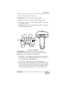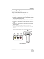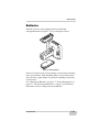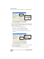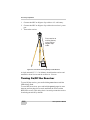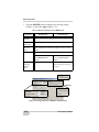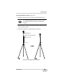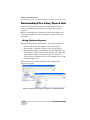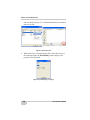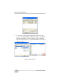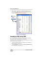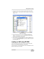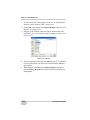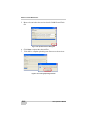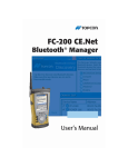
1
/PERATORlS-ANUAL P O S I T I O N I N G S Y S T E M S GR-5 Operator’s Manual Part Number 7010-1004 Rev A ©Copyright Topcon Positioning Systems, Inc. February, 2011 All contents in this manual are copyrighted by Topcon. All rights reserved. The information contained herein may not be used, accessed, copied, stored, displayed, sold, modified, published, distributed, or otherwise reproduced without express written consent from Topcon. ECO#4074 TOC Table of Contents Preface .................................................................. vii Terms and Conditions ...................................................... Manual Conventions ........................................................ Additional Documentation ............................................... Supported Firmware Versions ......................................... vii x xi xi Chapter 1 Introduction .......................................................... 1-1 Principles of Operation .................................................... GNSS Overview ........................................................ Calculating Absolute Positions ........................... Essential Components for Quality Surveying .... Calculating Differential Positions ...................... Conclusion .......................................................... GR-5 Receiver ................................................................. GR-5 Features ........................................................... MINTER ............................................................. Data and Power Ports ......................................... External Radio Antenna Connector .................... Connector ............................................................ SDHC and SIM Card Slots ................................. Batteries ..................................................................... Cables ........................................................................ Other Accessories ...................................................... Optional Accessories ................................................. Option Authorization File (OAF) .................................... 1-3 1-3 1-4 1-4 1-5 1-8 1-8 1-10 1-10 1-15 1-16 1-17 1-17 1-19 1-20 1-21 1-23 1-26 Chapter 2 Pre-survey Preparation ........................................ 2-1 Installing Topcon Software .............................................. 2-2 Installing PC-CDU .................................................... 2-2 Installing TRU ........................................................... 2-3 P/N 7010-1004 i Table of Contents Installing the Optional SDHC and SIM Cards ................. Charging the Batteries ...................................................... About the Chargers .................................................... Charging Temperatures ............................................. Charging the Batteries before First Use ..................... Charging Procedure ................................................... Leaving the Batteries on Charge ................................ Power Management .......................................................... Powering the Receiver ..................................................... Using the Detachable Batteries .................................. Attaching the Batteries ........................................ Detaching the Batteries ....................................... Assembling the AA Battery Shell ....................... Surveying while Charging ................................... Changing the Batteries while Surveying ............. Using an Auxiliary Power Source ............................. Turning On/Off the Receiver ..................................... Connecting the Receiver and a Computer ........................ Establishing a Wireless Connection .......................... Establishing an Serial (RS232) Cable Connection .... Establishing a USB Connection ................................. Bluetooth Module Configuration ..................................... Collecting Almanacs and Ephemerides ............................ 2-4 2-7 2-7 2-9 2-9 2-9 2-10 2-11 2-14 2-15 2-16 2-16 2-17 2-18 2-18 2-18 2-20 2-21 2-21 2-23 2-24 2-24 2-27 Chapter 3 GR-5 Configuration .............................................. 3-1 Managing the Radio Modem ............................................ Connecting with the Radio Modem ........................... Modem Configuration ............................................... Configuring a Digital UHF Radio Modem ........ Configuring an FH915+ Radio Modem .............. Configuring a Satel Radio Modem ..................... Configuring the Receiver Using TRU .............................. Configuring the Receiver Using PC-CDU ....................... MINTER Configuration ................................................... ii 3-2 3-3 3-4 3-5 3-9 3-14 3-19 3-29 3-39 GR-5 Operator’s Manual Table of Contents Chapter 4 GR-5 Receiver Setup and Survey ....................... 4-1 Receiver Setup ................................................................. Step 1: Set up the Receivers ...................................... Step 2: Measure Antenna Height .............................. Step 3: Collect Data .................................................. MINTER Operation ......................................................... Static Surveying for Base Stations .................................. Kinematic (Stop & Go) Surveying for Rover Stations .... Real Time Kinematic Surveying ..................................... 4-1 4-1 4-3 4-7 4-8 4-11 4-12 4-13 Chapter 5 Receiver and File Maintenance ........................... 5-1 Downloading Files to a Computer ................................... Downloading Files Using Topcon Link .................... ...Using Windows Explorer ................................ ...Using Topcon Link .......................................... Downloading Files Using TRU ................................. Deleting Files from the Receiver’s SDHC Card Using PC-CDU ................................................................ Deleting Files from the Receiver Using TRU ................. Managing Receiver Memory ........................................... Initializing the File System .............................................. Initializing the File System Using TRU .................... Managing Receiver Options ............................................ Checking the Receiver’s OAF using TRU ................ Checking the Receiver’s OAF using PC-CDU ......... Loading an OAF using TRU ..................................... Loading an OAF using PC-CDU .............................. Clearing the NVRAM ...................................................... Clearing the NVRAM Using the MINTER .............. Clearing the NVRAM Using TRU ............................ Clearing the NVRAM Using PC-CDU ..................... Changing Receiver Modes ............................................... Entering Extended Information Mode ...................... Sleep (Off) Mode ...................................................... Loading New Firmware Using TRU ............................... P/N 7010-1004 5-1 5-2 5-2 5-3 5-5 5-7 5-9 5-10 5-11 5-11 5-11 5-12 5-12 5-14 5-15 5-17 5-17 5-18 5-18 5-19 5-19 5-20 5-21 iii Table of Contents Chapter 6 Troubleshooting .................................................. 6-1 Check This First! .............................................................. Troubleshooting Quick List ............................................. Powering Problems .......................................................... Receiver Problems ............................................................ TX RX LED Blink Pattern on Error Conditions .............. Obtaining Technical Support ........................................... Phone ......................................................................... Email .......................................................................... Website ...................................................................... 6-1 6-2 6-3 6-4 6-8 6-9 6-10 6-10 6-11 Appendix A Specifications ...................................................... A-1 Receiver Specifications .................................................... General Details .......................................................... GPS Board Details ..................................................... Bluetooth Module Details .......................................... Internal TPS Spread Spectrum Modem Details ......... Internal Topcon UHF Modem General Specification Details ............................................... Internal UHF Satel Modem Details ........................... Optional GSM/GPRS Module Details ....................... Connector Specifications .................................................. Radio (Modem) RF Connector .................................. Power Connector ....................................................... Serial C-RS232 Connector ........................................ USB Connector .......................................................... A-1 A-1 A-8 A-9 A-10 A-11 A-12 A-13 A-14 A-14 A-15 A-16 A-17 Appendix B Safety Warnings ................................................... B-1 General Warnings ............................................................. B-1 Battery Pack Warnings ..................................................... B-2 Usage Warnings ............................................................... B-3 Appendix C Regulatory Information ....................................... C-1 FCC Compliance .............................................................. C-1 Community of Europe Compliance .................................. C-2 iv GR-5 Operator’s Manual Table of Contents WEEE Directive .............................................................. C-2 Appendix D Warranty Terms .................................................... D-1 Index P/N 7010-1004 v Table of Contents Notes: vi GR-5 Operator’s Manual Preface Preface Thank you for purchasing this Topcon product. The materials available in this Manual (the “Manual”) have been prepared by Topcon Positioning Systems, Inc. (“TPS”) for owners of Topcon products, and are designed to assist owners with the use of the receiver and its use is subject to these terms and conditions (the “Terms and Conditions”). NOTICE Please read these Terms and Conditions carefully. Terms and Conditions USE This product is designed to be used by a professional. The user should have a good knowledge of the safe use of the product and implement the types of safety procedures recommended by the local government protection agency for both private use and commercial job sites. COPYRIGHT All information contained in this Manual is the intellectual property of, and copyrighted material of TPS. All rights are reserved. Do not use, access, copy, store, display, create derivative works of, sell, modify, publish, distribute, or allow any third party access to, any graphics, content, information or data in this Manual without TPS’ express written consent and may only use such information for the care and operation of the receiver. The information and data in this Manual are a valuable asset of TPS and are developed by the expenditure of considerable work, time and money, and are the result of original selection, coordination and arrangement by TPS. P/N 7010-1004 vii Preface TRADEMARKS GR-5™, TRU™, PC-CDU™, Topcon Tools™, Topcon Link™, TopSURV™, Topcon® and Topcon Positioning Systems™ are trademarks or registered trademarks of TPS. Windows® is a registered trademark of Microsoft Corporation. The Bluetooth® word mark and logos are owned by Bluetooth SIG, Inc. and any use of such marks by Topcon Positioning Systems, Inc. is used under license. Other product and company names mentioned herein may be trademarks of their respective owners. DISCLAIMER OF WARRANTY EXCEPT FOR ANY WARRANTIES IN AN APPENDIX OR A WARRANTY CARD ACCOMPANYING THE PRODUCT, THIS MANUAL AND THE RECEIVER ARE PROVIDED “AS-IS.” THERE ARE NO OTHER WARRANTIES. TPS DISCLAIMS ANY IMPLIED WARRANTY OF MERCHANTABILITY OR FITNESS FOR ANY PARTICULAR USE OR PURPOSE. TPS AND ITS DISTRIBUTORS SHALL NOT BE LIABLE FOR TECHNICAL OR EDITORIAL ERRORS OR OMISSIONS CONTAINED HEREIN; NOR FOR INCIDENTAL OR CONSEQUENTIAL DAMAGES RESULTING FROM THE FURNISHING, PERFORMANCE OR USE OF THIS MATERIAL OR THE RECEIVER. SUCH DISCLAIMED DAMAGES INCLUDE BUT ARE NOT LIMITED TO LOSS OF TIME, LOSS OR DESTRUCTION OF DATA, LOSS OF PROFIT, SAVINGS OR REVENUE, OR LOSS OF THE PRODUCT’S USE. IN ADDITION TPS IS NOT RESPONSIBLE OR LIABLE FOR DAMAGES OR COSTS INCURRED IN CONNECTION WITH OBTAINING SUBSTITUTE PRODUCTS OR SOFTWARE, CLAIMS BY OTHERS, INCONVENIENCE, OR ANY OTHER COSTS. IN ANY EVENT, TPS SHALL HAVE NO LIABILITY FOR DAMAGES OR OTHERWISE TO YOU OR ANY OTHER PERSON OR ENTITY IN EXCESS OF THE PURCHASE PRICE FOR THE RECEIVER. LICENSE AGREEMENT Use of any computer programs or software supplied by TPS or downloaded from a TPS website (the “Software”) in connection with the receiver constitutes acceptance of these Terms and Conditions in this Manual and an agreement to abide by these Terms and Conditions. The user is granted a personal, non-exclusive, non-transferable license to use such Software under the terms stated viii GR-5 Operator’s Manual Terms and Conditions herein and in any case only with a single receiver or single computer. You may not assign or transfer the Software or this license without the express written consent of TPS. This license is effective until terminated. You may terminate the license at any time by destroying the Software and Manual. TPS may terminate the license if you fail to comply with any of the Terms or Conditions. You agree to destroy the Software and manual upon termination of the use of the receiver. All ownership, copyright and other intellectual property rights in and to the Software belong to TPS. If these license terms are not acceptable, return any unused software and manual. CONFIDENTIALITY This Manual, its contents and the Software (collectively, the “Confidential Information”) are the confidential and proprietary information of TPS. You agree to treat TPS’ Confidential Information with a degree of care no less stringent that the degree of care you would use in safeguarding your own most valuable trade secrets. Nothing in this paragraph shall restrict you from disclosing Confidential Information to your employees as may be necessary or appropriate to operate or care for the receiver. Such employees must also keep the Confidentiality Information confidential. In the event you become legally compelled to disclose any of the Confidential Information, you shall give TPS immediate notice so that it may seek a protective order or other appropriate remedy. WEBSITE; OTHER STATEMENTS No statement contained at the TPS website (or any other website) or in any other advertisements or TPS literature or made by an employee or independent contractor of TPS modifies these Terms and Conditions (including the Software license, warranty and limitation of liability). SAFETY Improper use of the receiver can lead to injury to persons or property and/or malfunction of the product. The receiver should only be repaired by authorized TPS warranty service centers. Users should review and heed the safety warnings in an Appendix. MISCELLANEOUS The above Terms and Conditions may be amended, modified, superseded, or canceled, at any time by TPS. The above Terms and Conditions will be governed by, and construed in accordance with, the laws of the State of California, without reference to conflict of laws. P/N 7010-1004 ix Preface Manual Conventions This manual uses the following conventions: Example Description File Exit Connection Frequency Enter NOTICE TIP NOTICE CAUTION WARNING x Click the File menu and click Exit. Indicates the name of a dialog box or screen. Indicates a field on a dialog box or screen, or a tab within a dialog box or screen. Press or click the button or key labeled Enter. Further information to note about the configuration, maintenance, or setup of a system. Supplementary information that can help to configure, maintain, or set up a system. Supplementary information that can have an affect on system operation, system performance, measurements, or personal safety. Notification that an action has the potential to adversely affect system operation, system performance, data integrity, or personal health. Notification that an action will result in system damage, loss of data, loss of warranty, or personal injury. GR-5 Operator’s Manual Additional Documentation DANGER Under no circumstances should this action be performed. Additional Documentation The following documentation can be useful while working with the GR-5 receiver: • TRU Reference Manual (7010-0908) – explains how to install, set up, and use the TRU software on desktop computers and hand-held controllers. • PC-CDU Reference Manual (31-000004-01) – explains how to install, set up, and use the PC-CDU software. Supported Firmware Versions This manual corresponds to the following versions of firmware for the GR-5: • GNSS firmware version 3.5 • FH915 Plus radio modem version 1.4p0 • Satel radio modem version 3.44f • Digital radio modem version 1.6RevG If new versions of the firmware are released, the user can load them to the GR-5 as described on “Loading New Firmware Using TRU” on page 5-21. P/N 7010-1004 xi Preface Notes: xii GR-5 Operator’s Manual Chapter 1 Introduction The GR-5 receiver is a multi-frequency, GNSS receiver built to be the most advanced and compact receiver for the surveying market. The receiver is a multi-function, multi-purpose receiver intended for precision markets. Precision markets means markets for equipment, subsystems, components and software for surveying, construction, commercial mapping, civil engineering, precision agriculture and land-based construction and agriculture machine control, photogrammetry mapping, hydrographic and any use reasonably related to the foregoing. Using a full wave antenna, the GR-5 can receive and processes multiple signal types, including the latest GPS L2C and GLONASS C/A L2, GPS L5 and GALILEO1 signals. Driven by the augmented Paradigm™ G3 chip, the board provides 216 universal channels and up to 100 Hz position and measurement update rates. GNSS tracking capabilities, dual-frequency RTK, SBAS functionality, extensive communication capabilities, removable memory for files combine to provide a positioning system efficient, secure, and appropriate for any survey. Several other unique features, including multipath mitigation, adjustable phase-locked loop (PLL) and delay-locked loop (DLL) parameters, offer a reliable and versatile reception of weak signals even in degraded signal environments. The receiver provides the functionality, availability, and integrity. 1. The GR-5 tracks the GIOVE-A and GIOVE-B test satellites. The signals from these satellites are used for signal evaluation and test purposes only. P/N 7010-1004 1-1 Introduction Figure 1-1. GR-5 Receiver 1-2 GR-5 Operator’s Manual Principles of Operation Principles of Operation Surveying with a professional-grade GNSS receiver can provide users with accurate and precise positioning; a fundamental requirement for any surveying project. This section gives an overview of existing and proposed Global Navigation Satellite Systems (GNSS) and receiver functions so that basic operating principles can be applied. GNSS Overview Currently, two Global Navigation Satellite Systems (GNSS)1 offer line-of-sight radio navigation, positioning, and timing services on a global, all-weather scale to any user equipped with a GNSS tracking receiver: • GPS - the Global Positioning System maintained and operated by the United States Department of Defense. For information on the status of this system, visit the US Naval Observatory website (http://tycho.usno.navy.mil/) or the US Coast Guard website (http://www.navcen.uscg.gov/). • GLONASS - the GLobal NAvigation Satellite System maintained and operated by the Russian Federation Ministry of Defense. For information on the status of this system, visit the Coordinational Scientific Information Center website (http://www.glonassianc.rsa.ru/). Despite the numerous technical differences in the implementation of these systems, both satellite positioning systems have three essential components: • Space - GPS and GLONASS satellites orbit approximately 12,000 nautical miles above Earth, and are equipped with an atomic clock and a radio. These satellites broadcast ranging signals and various digital information (ephemerides, almanacs, time and frequency corrections, and so forth). 1. GALILEO navigation satellite system currently being built by the European Union (EU) and European Space Agency (ESA). P/N 7010-1004 1-3 Introduction • Control - Ground stations located around the Earth that monitor the satellites and upload data, including clock corrections and new ephemerides (satellite positions as a function of time), to ensure the satellites transmit data properly. • User - The community and military that use GNSS receivers to calculate positions. Calculating Absolute Positions When calculating an absolute position, a stationary or moving receiver determines its three-dimensional position with respect to the origin of an Earth-Center Earth-Fixed coordinate system. To calculate this position, the receiver measures the distance (called pseudoranges) between it and at least four satellites. The measured pseudoranges are corrected for clock differences (receiver and satellites) and signal propagation delays due to atmospheric effects. The positions of the satellites are computed from the ephemeris data transmitted to the receiver in navigation messages. When using a single satellite system, the minimum number of satellites needed to compute a position is four. In a mixed satellite scenario (GPS and GLONASS), the receiver must lock onto five or more satellites to account for the different time scales used in these systems and to obtain an absolute position. Essential Components for Quality Surveying Achieving quality positioning results from the GR-5 requires an understanding of the following elements: • Accuracy - The accuracy of a position that is delivered by a GNSS receiver primarily depends upon the observed satellite geometry (Geometric Dilution of Precision, or GDOP) and the measurement (ranging) errors. – Differential positioning techniques (DGPS and RTK) can be used to almost completely remove all major GNSS error sources, such as atmospheric and orbital errors. – The more satellites that are in view, the stronger the signal, the lower the GDOP number will be, leading to the highest positioning accuracy. For DGPS and RTK operations, it is important to consider that the GDOP is dependent on the 1-4 GR-5 Operator’s Manual Principles of Operation number of common satellites in view at both the Base and the Remote receivers. – The quality of observed measurements can also affect accuracy, and for this reason Topcon GNSS products use sophisticated and patented techniques to produce highly precise measurements. However, these measurements can still be adversely affected by nearby natural and man-made objects that block, interrupt, reflect, or partially obscure satellite signals. • Availability - While a low number of satellites may adversely affect accuracy, if very few satellites are visible this may result in no position being available at all. A minimum of 4 GPS or 4 GLONASS, or 5 GPS+GLONASS (mixed) satellites must be visible at all times. • Integrity - Fault tolerance and redundancy allow a position solution to have greater integrity, increasing its reliability for the user. Several factors combine to provide fault tolerance, including: – Five or more visible satellites for only GPS or only GLONASS; six or more satellites for a mixed scenario. As the total number of satellites increases, so does the measurement redundancy and the inherent reliability of the position. – Satellite Based Augmentation Systems (WAAS, EGNOS, and so on) creates and transmit, along with DGPS corrections, data integrity information (for example, satellite health warnings). – Current ephemerides and almanacs. Calculating Differential Positions DGPS, or Differential GPS, is a relative positioning technique where the measurements from two or more remote receivers are combined and processed using sophisticated algorithms to calculate the receivers' relative coordinates with high accuracy. DGPS accommodates various implementation techniques that can be classified according to the following criteria: P/N 7010-1004 1-5 Introduction • The type of GNSS measurements used, either code-phase differential measurements or carrier-phase differential measurements • If real-time or post-mission results required. Real-time applications can be further divided according to the source of differential data and communication link used. With DGPS in its most traditional approach, one receiver is placed at a known surveyed location and is referred to as the reference receiver or base station. Another receiver is placed at an unknown location and is referred to as the remote receiver or rover. The reference station collects the code-phase and carrier-phase measurements from each GNSS satellite in view. • For real-time applications, these satellite measurements and the reference station coordinates are then combined to form industry standard RTCM1 messages that are broadcast to the remote receiver(s) using a data communication link. The remote receiver applies the transmitted measurement information to its observed measurements of the same satellites. • For post-mission applications, the simultaneous measurements from reference and rover stations are recorded to the receiver's memory card (not sent over a communication link). Later, the data is downloaded to a computer, combined, and processed. Using this post-processing technique, the spatially correlated errors - such as satellite orbital errors, ionospheric errors and tropospheric errors - can be significantly reduced, thus improving the position solution accuracy. This is particularly true when the remote receiver is stationary. 1. [RTCM FOOTNOTE] The Radio Technical Commission for Maritime Services (RTCM) defines global standards for communication messages and protocols that are used in the GNSS positioning industry. In support of this standards-based approach, Topcon recommends use of the latest RTCM message formats (v3 or greater) for all RTK and DGPS communication needs. Several legacy correction message formats are also provided by Topcon GNSS products in order to support interoperability with older GNSS systems, but their use is now deprecated. 1-6 GR-5 Operator’s Manual Principles of Operation Other differential positioning methods and systems also exist, including, maritime radio beacons, commercial geostationary satellites (as with the OmniSTAR service) and satellite based augmentation systems (WAAS, EGNOS, MSAS). For use of these other systems additional hardware and/or subscription fees may be required that are separate from the GR-5 system. The Real-time Kinematic (RTK) method is the most common method of precision real-time surveying. RTK operation requires at least two receivers collecting simultaneous GNSS data and a reliable lowlatency communication link between the receivers. As with DGPS described earlier, one of the receivers is usually at a known location (Base) and the other is at an unknown location (Rover). The Base receiver collects precise carrier phase measurements, generates RTK corrections and transmits this data to the Rover receiver. The Rover processes this transmitted data with its own carrier phase observations to compute its relative position with high accuracy, thus achieving an RTK accuracy of up to 10mm horizontal and 15mm vertical. The GR-5 supports three widely used network RTK implementation techniques, specifically, VRS, FKP, and MAC. • Virtual reference station (VRS). The network software collects raw data measurements from several reference stations that belong to a network. These data are then estimated and processed to produce ionospheric and tropospheric corrections for each station and each satellite. After the rover receiver transmits its approximate position to the network software using an NMEA GGA message, the corrections are interpolated to the position of the rover. Interpolated corrections are used to reconstruct the measurements of pseudo range and carrier phase of a virtual reference station located close to the rover. The reconstructed measurements are transmitted to the rover as RTCM or CMR messages. • Area correction parameters (FKP). Unlike the VRS approach, the network software calculates coefficients for modeling ionospheric, tropospheric, and orbital effects for each satellite over a specific network area. The coefficients are then transmitted to the rover as RTCM message type 15, so that the rover can P/N 7010-1004 1-7 Introduction generate the corrections and apply them to its own observations to compute the position with high accuracy. • Master-auxiliary concept (MAC). This approach assumes the usage of one master reference station and a number of auxiliary reference stations to generate network correction messages. The master station transmits full raw observations and coordinate information while auxiliary stations transmit ionospheric and geometric correction differences and coordinate differences calculated between the master and each auxiliary station. The rover accepts all these data as RTCM 3 messages and applies them to get its own accurate position. Conclusion This overview simply outlines the basics of satellite positioning. For more detailed information, visit the Topcon website (http://www.topconpositioning.com/). GR-5 Receiver When power is turned on and the receiver self-test completes, the receiver’s 216 channels initialize and begin tracking visible satellites. Each of the receiver’s channels can be used to track any one of the GPS, GLONASS, or GALILEO1 signals. The number of channels available allows the receiver to track all visible global positioning satellites at any time and location. An internal full wave GNSS antenna equipped with a low noise amplifier (LNA) and the receiver’s radio frequency (RF) device are connected with a coaxial cable. The wide-band signal received is down-converted, filtered, digitized, and assigned to different channels. The receiver processor controls the process of signal tracking. 1. The GR-5 tracks the GIOVE-A and GIOVE-B test satellites. The signals from these satellites are used for signal evaluation and test purposes only. 1-8 GR-5 Operator’s Manual GR-5 Receiver Once the signal is locked in the channel, it is demodulated and necessary signal parameters (carrier and code phases) are measured. Also, broadcast navigation data are retrieved from the navigation frame. After the receiver locks on to four or more satellites, its absolute position in WGS-84 and the time offset between the receiver clock and GPS time are computed. This information and the measurement data can be stored in the optional SDHC card and downloaded later onto a computer, then processed using a post-processing software package. When the receiver operates in RTK mode, raw data measurements can also be recorded into the receiver’s internal memory. This allows the operator to double check real-time results obtained in the field. The GR-5 comes in one of the following configurations: • with an FH915 Plus TX/RX/RP1 radio modem • with an FH915 Plus TX/RX/RP radio modem and a GSM/GPRS module • with a Digital radio modem • with a Digital radio modem and GSM/GPRS or CDMA module (for US customers) • with a Satel radio modem and a GSM/GPRS module Depending on your options, capabilities of the receiver include: • Multipath reduction • Satellite based augmentation systems (WAAS, EGNOS, and so forth). • Adjustable phase locked loop (PLL) and delay lock loop (DLL) parameters • Configurable internal long-range radio for DGPS and RTK communications as well as Network based DGPS and RTK solutions • Automatic data logging 1. RP = repeater P/N 7010-1004 1-9 Introduction • Detailed control over numerous receiver settings, such as mask angles, static/dynamic tracking modes, startup behavior, etc. • Setting different survey parameters • High frequency measurement (up to 100 Hz) and position output rates • Static or dynamic modes GR-5 Features The GR-5 receiver’s advanced design reduces the number of cables required for operation, allowing for more reliable and efficient surveying. The GR-5 is a 216-channel GNSS receiver with two data ports, a power port, a multi-system GNSS board, and a radio modem communications board, an interface for controlling and viewing data logging, and also includes: • Two external, detachable batteries • USB and Serial data ports • External memory card slot • Internal radio modem • Bluetooth® wireless technology module • Interface for controlling and viewing data logging through MINTER display • Optional GSM/GPRS module. • SIM card slot MINTER The MINTER is the receiver’s LED display panel used to display and control data input and output (Figure 1-2). The Battery LEDs display the power status for each battery: • Green – indicates greater than 85% charge. • Orange – indicates an intermediate charge. 1-10 GR-5 Operator’s Manual GR-5 Receiver • Red – indicates less than 15% charge. The STAT LED displays the status of tracked satellites. • Red blink – receiver is on, but no satellites being tracked. • Green blink – receiver is on and tracking satellites; one blink per tracked GPS satellite. • Orange blink – receiver is on and tracking satellites; one blink per tracked GLONASS satellite. REC RX TX STAT BT Battery FUNCTION Battery FUNCTION Power Button FUNCTION Button Figure 1-2. GR-5 MINTER The REC LED displays the data recording status. See “The FUNCTION button” on page 1-13 for more information on REC LED behavior when using the FUNCTION button. • Green blinks – each blink indicates that data is being written to the SDHC card. See “SDHC and SIM Card Slots” on page 1-17 for recommendations on SD/SDHC cards. • Solid Orange – indicates the receiver is changing modes. • Orange blinks – indicates that the receiver is checking its internal file system (after clearing the NVRAM or loading new firmware). During this operation, the file system is not accessible for CDU (control display unit) applications or for data recording. This P/N 7010-1004 1-11 Introduction operation may require from fractions of a second to several minutes, depending on the circumstances and the amount of internal memory. • Solid Red – indicates a fault condition with the receiver (no more memory, no SDHC card inserted, a hardware problem, or an improper OAF). Table 1-2 on page 1-13 describes the REC LED status when using the FUNCTION button. The RX TX LED displays the status of the modem. Table 1-1 describes the LED colors and patterns for the different modems available for the GR-5 receiver. Table 1-1. RX TX LED Indications • No light – modem is turned off. • Green flashes – modem is in receiver mode. • Solid Green – a radio link has been established; modem is ready to receive data. FH915 Plus/ Digital/Satel Modems • Solid Green plus Red flashes – modem is receiving data. • Solid Red – modem is in transmitter mode. • Red flashes – a fault condition has been detected. Check the condition of the radio modem’s antenna to ensure it is undamaged, and is connected properly and securely. Also make sure nothing interrupts the signal. • Red flashes plus Green flashes – modem is in command mode. • Solid Orange (Red and Green) – the modem is initializing. • Green flashes – the modem is on, registered on the network, and is waiting for incoming calls (Slave mode). GSM/GPRS • Solid Red – a connection has been established. • Green flashes – the modem is in direct control mode (Daisy Chain). • Orange flashes – an error has occurred (initialization error, wrong PIN code, and so forth). The BT LED indicates the level of activity at the Bluetooth wireless technology communication link: • Blue flashes – the Bluetooth module is on but no connection is established. 1-12 GR-5 Operator’s Manual GR-5 Receiver • Solid blue light – the Bluetooth module is on and a connection has been established. • No light – the Bluetooth module is off. The Power button turns the receiver on and off. The FUNCTION button switches the receiver between information modes and post-processing modes, starts/stops data recording, and changes the baud rate of the serial port to 9600. See “MINTER Operation” on page 4-8 for more information. Table 1-2 on page 1-13 describes the REC LED status when using the FUNCTION button. Table 1-2. FUNCTION Button Operations and REC LED Status FUNCTION Key REC LED Status When data recording is off, and the FUNCTION key is... Not pressed No light No data recording. Orange blink Internal file system test in progress. Red No free memory; hardware problem with data recording. No SDHC card. If FUNCTION key mode is “LED blink mode switch” Pressed for < 1 second Orange Release to change information mode. If FUNCTION key mode is “Occupation mode switch” Orange No function. If FUNCTION key mode is “LED blink mode switch” Pressed for 1–5 seconds Green Release to start data recording (postprocessing occupation mode undefined). If FUNCTION key mode is “Occupation mode switch” Pressed for 5–8 seconds P/N 7010-1004 Green Release to start recording (Kinematic or Static post-processing occupation mode). Red Release to turn serial port A baud rate to 9600 bps. 1-13 Introduction Table 1-2. FUNCTION Button Operations and REC LED Status (Continued) FUNCTION Key Pressed for > 8 seconds REC LED No light Status No function. When data recording is on, and the FUNCTION key is... Red No free memory; hardware problem with data recording. If FUNCTION key mode is “LED blink mode switch” Green Not pressed Data recording started (post-processing occupation mode undefined). If FUNCTION key mode is “Occupation mode switch” Green Data recording started (Kinematic postprocessing occupation mode). Orange Data recording started (Static postprocessing occupation mode). If FUNCTION key mode is “LED blink mode switch” Pressed for < 1 second Orange Release to change information mode. If FUNCTION key mode is “Occupation mode switch” Orange Release to toggle between Static and Kinematic post-processing modes. Pressed for 1–5 seconds No light Release to stop data recording. Pressed for 5–8 seconds Red Release to turn serial port A baud rate to 9600 bps. Pressed for > 8 seconds No light No function (data recording still on). 1-14 GR-5 Operator’s Manual GR-5 Receiver Data and Power Ports The GR-5 has the following three ports (Figure 1-3): • USB – rimmed in yellow; used for high-speed data transfer and communication between the receiver and an external device. The body of the connector on the corresponding cable is yellow. • Serial Port A– rimmed in black; used for communication between the receiver and an external device. • Serial Port B – used internally and left free in the current release. • Serial Port C – used internally to connect the modem and receiver boards. • Serial Port D – used internally to connect the receiver board and Bluetooth module. • Power – rimmed in red; used to connect the receiver to an external power source. This port can also be used to charge the batteries. The body of the connector on the corresponding cable is red. USB (yellow) U S B Serial (black) S E R I A L Power (red) P O W E R Figure 1-3. GR-5 Ports P/N 7010-1004 1-15 Introduction External Radio Antenna Connector The radio antenna connects to the external antenna connector on the GR-5 radome (Figure 1-4). The radio antenna uses a reverse polarity TNC connection or BNC connection depending on the installed radio modem. External Antenna Connector Figure 1-4. GR-5 Radome and External Antenna Connector 1-16 GR-5 Operator’s Manual GR-5 Receiver Connector The bottom connector (Figure 1-5) connects the receiver to either a standard 5/8'' thread pole/adapter or the quick disconnect (see “The quick disconnect adapter” on page 1-24 for details). Bottom Connector for Standard Setups Figure 1-5. GR-5 Quick Connector SDHC and SIM Card Slots The SDHC and SIM card slots reside under the batteries near the base of the dome. Recommended SD/SDHC Cards: These cards were tested in the temperature range -30°C to 60°C (-22°F to 140°F). • Transcend® Ultra Industrial 2 GB • APRO® Industrial 4GB • SanDisk® Ultra II • Swissbit® Industrial 2GB The SDHC card slot is located to the left of the MINTER inside the battery compartment (Figure 1-6) and connects an optional SDHC card to the receiver board to provide memory. Once installed, the SDHC card usually remains inside the receiver. The data that resides on the SDHC card can be accessed via the USB or serial port, or Bluetooth wireless technology. A secure digital card can be purchased at a local computer supply store. P/N 7010-1004 1-17 Introduction The SIM card slot is located to the right of the MINTER inside the battery compartment and allows a standard SIM card to be installed in the receiver. Once installed, the SIM card provides a unique identification for the receiver’s GSM module and enables the receiver’s GSM functionality based on the subscribed services (the receiver board accesses the GSM module which accesses the SIM card). The SIM card usually remains inside the receiver. The GSM module with the SIM card installed can be accessed via TRU for configuration purposes. A SIM card can be purchased from a local cellular provider. Card Slot (for SDHC card) Figure 1-6. GR-5 Card Slot Example 1-18 GR-5 Operator’s Manual GR-5 Receiver Batteries The GR-5 receiver comes equipped with two detachable, rechargeable batteries (Figure 1-7) for powering the receiver. Figure 1-7. GR-5 Batteries The receiver draws power from one battery at a time before switching to the second battery. Each detachable battery can provide between 5hrs. and 10hrs. (approximate) of operation, depending on the mode of the receiver. See “Charging the Batteries” on page 2-7, “Power Management” on page 2-11, and “Powering the Receiver” on page 2-14 for detailed instructions on how to charge and use the batteries. P/N 7010-1004 1-19 Introduction Cables The GR-5 package includes standard communication and power cables for configuring the receiver and providing a power source to the receiver. Table 1-3 lists the cables included in the GR-5 package. Table 1-3. GR-5 Package Cables Cable Description Cable Illustration Power cable Connects the power supply unit to a grounded outlet. U.S. p/n 14-008052-01 Europe p/n 14-008054-01 Australia p/n 14-008053-01 Receiver power/charging cable Connects the receiver and the power supply unit via SAE connectors for battery charging. Body of connector is red. p/n 14-008016-03 USB cable Connects the receiver to an external device (controller or computer) for high-speed data transfer and receiver configuration. Body of connector is yellow. p/n 14-008070-01 Serial cable Connects the receiver to an external device (controller or computer) for data transfer and receiver configuration. Body of connector is black. p/n 14-008005-02 1-20 GR-5 Operator’s Manual GR-5 Receiver Other Accessories The power supply unit (p/n 22-034101-01) charges the internal batteries when connected to a grounded outlet (Figure 1-8). This unit converts the alternating current (AC) normally supplied from an electrical outlet to a direct current (DC) used to charge the batteries and/or power the receiver. CAUTION The power supply unit should only be used for C charging the batteries. Do not use as a power source during surveying. The power supply unit can be connected to the charging cradle or directly to the receiver. For details, see the power related sections in Chapter 2. Figure 1-8. Power Supply Unit P/N 7010-1004 1-21 Introduction The modem antenna Spread Spectrum or UHF includes support for a GSM/GPRS modem (Figure 1-9 on page 1-22). The Spread Spectrum antenna is a reverse polarity TNC RF connection (p/n 30-030012-01) and a UHF antenna is a BNC connection (p/n 30-070003-01 UHF 410-440 or p/n 30-050503-01 UHF 450-470). SS/GSM Antenna UHF/GSM Antenna Figure 1-9. Modem Antenna The GR-5 2m fixed height Tripod and Pole The heavy duty tripod (22-050501-01) is shown in Figure 1-10. The pole (22-050908-01) is not pictured. Figure 1-10. Tripod For more details on the accessories and package options available for the GR-5, contact a local Topcon dealer. 1-22 GR-5 Operator’s Manual GR-5 Receiver Optional Accessories Topcon offers a wide variety of accessories especially designed to extend job reliability and efficiency. For more details on the optional accessories available for the GR-5, contact a local Topcon dealer. The universal tribrach and tribrach adapter1 (p/n 22-006008-01 and p/n 22-006009-011) are used to level the tripod and secure the receiver or antenna to the tripod (Figure 1-11). Figure 1-11. Universal Tribrach and Tribrach Adapter The precision tribrach adapter (Figure 1-12) is used to precisely center, align, and level the tripod over a point. The horizontal spacer (p/n 60419) inserts into the precision tribrach and allows the receiver to sit securely on the precision tribrach. Figure 1-12. Precision Tribrach Adapter and Horizontal Spacer 1. The universal tribrach and tribrach adapter is not needed when using the heavy duty tripod (22-050501-01). P/N 7010-1004 1-23 Introduction The quick disconnect adapter (p/n 02-850905-01) connects to the range pole for the receiver to slip into the top. Using the side clips, the receiver can be quickly connected to/disconnected from the range pole (Figure 1-13). Figure 1-13. Quick Disconnect A hand-held controller (Figure 1-14) allows the GR-5 Base and Rover systems to be configured and monitored directly in the field. TopSURV (field data collection software) and TRU (receiver configuration and monitoring software) can be used on Topcon controllers to configure and manage the receiver. FC-25 FC-2500 Figure 1-14. Hand-held Controller Examples 1-24 GR-5 Operator’s Manual GR-5 Receiver The ODU-to-alligator clips cable (p/n 14-008097-01LF) connects the charging cradle or receiver to an auxiliary battery for powering the receiver during survey operations (Figure 1-15). Figure 1-15. Auxiliary Power Cable – ODU-to-Alligator Clips The AA battery pack (Figure 1-16) holds four AA batteries to provide a portable backup power source for the receiver. Due to variances in AA battery capacity, and the mode of the receiver and type of modem, the amount of time the receiver is powered varies. See “Assembling the AA Battery Shell” on page 2-17 for details on how to attach the pack to the GR-5. Figure 1-16. AA Battery Pack CAUTION Do not use rechargeable AA batteries. C Do not use the AA battery shell when the radio modem is in transmitter mode. Figure 1-17. Cradle-to-receiver charging cable (p/n 14-008072-01 (1.5m long) p/n 14-008072-02 (0.5 m long) Connects the receiver to the charging cradle for external power (Figure 1-18). Figure 1-18. Cradle-to-receiver Charging Cable P/N 7010-1004 1-25 Introduction Battery Recharger (01-050911-01) Charges the batteries. See “Charging the Batteries” on page 2-7. To grounded outlet Figure 1-19. Battery Recharger Option Authorization File (OAF) Topcon Positioning Systems issues an Option Authorization File (OAF) to enable the specific options that customers purchase. An Option Authorization File allows customers to customize and configure the receiver according to particular needs, thus only purchasing those options needed. Typically, all receivers ship with a temporary OAF that allows it to be used for a predetermined period of time. When the receiver is purchased, a new OAF permanently activates purchased options. Receiver options remain intact when clearing the NVRAM or resetting the receiver. The OAF enables the following kinds of functions. For a complete list of available options and details, visit the TPS website or consult a TPS dealer. 1-26 GR-5 Operator’s Manual Option Authorization File (OAF) • Type of signal (standard L1; optional L2, L5 GPS, GLONASS, GALILEO)1 • Update rate standard 1Hz (optional 10, 20, 50, or 100 Hz) • RTK at 10, 20, 50, and 100 Hz • RTCM/CMR Input/Output • Advanced multipath reduction • Satellite Based Augmentation System (WAAS/EGNOS/MSAS) • RS-232C and USB port connectivity 1. There is no separate option for GALILEO signals in the OAF. The GR-5 tracks the GIOVE-A and GIOVE-B test satellites. The signals from these satellites are used for signal evaluation and test purposes only. P/N 7010-1004 1-27 Introduction Notes: 1-28 GR-5 Operator’s Manual Chapter 2 Pre-survey Preparation Before beginning to survey with the GR-5 receiver, the following software needs to be installed and configurations need to be applied: Install receiver configuration software See “Installing Topcon Software” on page 2-2. Optional: install SDHC card and/or SIM card See “Installing the Optional SDHC and SIM Cards” on page 2-4. Charge the batteries See “Charging the Batteries” on page 2-7. Enable power source settings (either attached or external) See “Power Management” on page 2-11 and “Powering the Receiver” on page 2-14. Configure the Bluetooth wireless technology module See “Bluetooth Module Configuration” on page 2-24. Collect almanacs and ephemerides (after first-time configuration activities as described in Chapter 3) See “Collecting Almanacs and Ephemerides” on page 2-27. This chapter also discusses connecting batteries to the receiver, connecting the receiver and a computer, and powering the receiver using different sources. P/N 7010-1004 2-1 Pre-survey Preparation Installing Topcon Software The Topcon GPS+ CD includes the following software programs used for configuring and maintaining the receiver. This software is also available on the TPS website to registered users. • PC-CDU Lite ver. 7.12 or newer • TRU ver. 2.2 or newer If installing the program(s) from the GPS+ CD, insert the CD into the computer’s CD-ROM drive. If downloading the program(s) from the website, extract the program’s files into a folder on the hard drive. The following sections describe installing this software, and other sections throughout the manual describe using this software with the receiver. Installing PC-CDU PC-CDU™ is a comprehensive Windows® software product designed for controlling GNSS receivers developed by Topcon Positioning Systems. PC-CDU uses the GPS Receiver Interface Language (GRIL) to configure various receiver settings and diagnose receiver performance. The PC-CDU software exists in two versions: a full-functionality version called PC-CDU MS and a reduced-functionality version called PC-CDU Lite. PC-CDU Lite is available for free on the Topcon website or the GPS+ CD. Computer requirements for PC-CDU are: Windows® 98 or newer and an RS-232C or USB port, or Bluetooth capable. Use PC-CDU version 7.12 or newer to correctly configure the receiver. NOTICE 2-2 Refer to the PC-CDU Reference Manual for full details on installing and using PC-CDU. GR-5 Operator’s Manual Installing Topcon Software To Install PC-CDU: 1. Create a PC-CDU folder on the hard drive and place the compressed PC-CDU zip file (retrieved from either the website or the GPS+ CD) in this folder. 2. Navigate to the PC-CDU folder and double-click the PCCDU_MS zip file. 3. Extract the PCCDU.EXE and associated *.dll file to the PC-CDU folder (Figure 2-1). 4. Create a shortcut on the computer’s desktop for quick access to PC-CDU (Figure 2-1). Figure 2-1. Extract Program and Create Shortcut To uninstall PC-CDU, navigate to the location of the *.exe file. Select the file and press Delete. Installing TRU TRU is a Windows® software application designed for configuring GNSS receivers, including GNSS boards, modem boards, and Bluetooth modules. Computer requirements for TRU are: Microsoft® Windows XP/ Vista/7 operating system and an RS-232C port or computer with Bluetooth wireless technology. Use TRU to correctly configure the receiver. P/N 7010-1004 2-3 Pre-survey Preparation To install TRU: 1. Navigate to the TRU folder, and double-click TRU.zip. 2. Extract TRU.exe to the TRU folder. 3. Double-click TRU.exe to run the installer, and then follow the on-screen instructions. After installation, shortcuts appear on the desktop and in the TRU menu. Figure 2-2. TRU Desktop Shortcut To uninstall TRU, navigate to the location of the *.exe file. Select the file, and press Delete. Each time TRU runs and configures the bluetooth module, TRU saves the settings in a file (btconf.ini). TRU automatically updates the file each time changes are made to the Bluetooth module’s settings. Installing the Optional SDHC and SIM Cards Behind each detachable battery is a slot for the optional SDHC card or the optional SIM card. The SDHC card provides memory space in which to save logged data; the SIM card provides access to communication over GSM, GPRS, or CDMA services. The SDHC card can be purchased at a local computer store; the SIM card can be purchased at a local cellular phone supply store. Although the user may install an SDHC card of any size, the receiver will recognize only up to 2 GB of memory. The recognizable capacity is controlled through the Memory option in an OAF. Once installed, the card(s) generally remains installed. The card can then be accessed via the receiver board using a data port or Bluetooth wireless technology. 2-4 GR-5 Operator’s Manual Installing the Optional SDHC and SIM Cards To install the SDHC card (Figure 2-3): 1. Ensure the receiver is turned off. 2. Remove the battery to the left of the MINTER. 3. Carefully insert the SDHC card, label side down, into the SDHC card slot located at the top of the battery compartment. Figure 2-3. Install SDHC Card CAUTION Use only industrial-grade SDHC cardsa. Before using any other SDHC cards, consult with TPS technical support about compatibility. Do not remove the card if the receiver is powered on. Damage to data may result from improper removal of the card. a. Recommended cards: Transcend® Ultra Industrial 2 GB, APRO® Industrial 4GB, SanDisk® Ultra II, or Swissbit® Industrial 2GB. Once the receiver is turned on, the receiver board will detect the SDHC card and it will be ready to use as needed. CAUTION P/N 7010-1004 Always initialize the file system on the installed SDHC card before the first use. Initialization procedure is described on “Initializing the File System” on page 5-11. 2-5 Pre-survey Preparation To install the SIM card (Figure 2-4): The SIM card must support Circuit Switched Data to communicate directly between receivers. The SIM card must have GPRS support to communicate over a TCP/IP network. NOTICE Both the Base and Rover receivers must have a SIM card installed (supporting Circuit Switched Data) and have subscriptions to the same service provider for proper communication. 1. Ensure the receiver is turned off. 2. Remove the battery to the right of the MINTER. 3. Carefully insert the SIM card, label side up, into the SIM card slot located at the top of the battery compartment. Figure 2-4. Install SIM Card Once the receiver is turned on, the receiver board will detect the SIM card and it will be ready to use as needed. 2-6 GR-5 Operator’s Manual Charging the Batteries Charging the Batteries About the Chargers The power supply unit or the battery charging cradle can be used to charge the batteries. The power supply unit (p/n 22-034101-01) charges the internal batteries when connected to a grounded outlet (Figure 1-8 on page 121). This unit converts the alternating current (AC) normally supplied from an electrical outlet to a direct current (DC) used to charge the batteries and/or power the receiver. CAUTION The power supply unit is designed for indoor use only. Do not use it in damp or wet environment. Do not expose the power supply to rain or snow. It should only be used for charging the batteries. Do not use as a power source during surveying. The power supply unit can be connected to the charging cradle or directly to the GR-5. The power supply has the following specifications: • input voltage – between 100 and 240 V AC • frequency of input power – between 50 Hz and 60 Hz • output voltage – 12 V [email protected] A (30 W) The battery charging cradle (Figure 2-5) connects to a standard power outlet using the power adapter cable and power cable/power supply unit. The charger has two ports, one button, and three LEDs. • The two ports connect the charger to either a receiver or an external power source. The ports charge or drain the batteries simultaneously. • The STATUS button activates the battery LEDs. P/N 7010-1004 2-7 Pre-survey Preparation Press STATUS to display the amount of charge for the corresponding battery. • The two battery LEDs display the percentage of charge in the attached battery. – Green: indicates greater than 85% charge. – Orange: indicates an intermediate charge. – Red: indicates less than 15% charge. • The power LED lights up when the charger is connected to an external power source; such as an electrical outlet or another power source (12 volt battery). Two power in/out ports Battery STATUS Button Battery Power Figure 2-5. Battery Charger with Batteries The battery charger can also be attached to a tripod, belt, or RTK pole to provide external power to the base station or rover. Before using the GR-5, fully charge the batteries for maximum operating time (Figure 2-6 on page 2-10). 2-8 GR-5 Operator’s Manual Charging the Batteries Charging Temperatures Charge the batteries only in temperatures between 32oF (0oC) and 113oF (45oC). 0oC 32oF An optimal charging temperature is between 50oF (10oC) and 77oF (25oC). If possible, charge the batteries within this temperature range. o 10 C 50oF 45oC 113oF 25oC 77oF Charging the Batteries before First Use The batteries are shipped from the factory without power. Fully charge the batteries before surveying. See “Charging Procedure” below for detailed instructions on how to charge the batteries. Charging Procedure There are two ways to charge the GR-5 detachable batteries: • while they are attached to the GR-5 • while they are attached to the charging cradle If the batteries are attached to the GR-5 or to the charging cradle, an approximately 6-hour charge cycle will fully charge the batteries; the batteries charge simultaneously. The Li-Ion batteries used in the battery packs should run at no less than 80% capacity after 500 charging cycles. These batteries do not need to be drained before recharging. To charge the batteries using the power supply unit: 1. Plug the receiver-to-SAE power cable into the receiver’s power input port. P/N 7010-1004 2-9 Pre-survey Preparation 2. Connect the receiver-to-SAE power cable and the power supplyto-outlet cable to the AC adapter. 3. Plug the power supply-to-outlet cable into an available outlet. Leave for approximately 6 hours to fully charge the batteries. To charge the batteries using the charging cradle: 1. Remove the batteries from the receiver and insert them into the charging cradle. 2. Connect the power cable to the power supply unit. 3. Connect the SAE connectors on the power adapter cable and power supply unit. 4. Connect the power adapter cable to one of the ports on the charging cradle (either port will charge both/either battery). 5. Plug the power supply to an available outlet. Leave for approximately 6 hours to fully charge the batteries. To grounded outlet Figure 2-6. Insert Batteries in Charger and Connect to Outlet Leaving the Batteries on Charge The batteries can be safely left in the receiver or the charging cradle once charging is complete. Doing so will not overcharge or damage the batteries. The batteries can also be attached/detached to/from the receiver or charging cradle at any time without harming the batteries, the 2-10 GR-5 Operator’s Manual Power Management receiver, or the cradle. When returning the batteries to the receiver or cradle, charging is automatically resumed. Power Management Topcon’s PC-CDU software provides an interface for various configuration, monitoring, and management functions for the receiver. For power management of the receiver, PC-CDU enables the power source, enables the charging mode, and displays the current voltage for the batteries. 1. Connect the receiver and computer. See “Connecting the Receiver and a Computer” on page 2-21 for this procedure. 2. Once connected, click Configuration Receiver. 3. Select the Power Mode drop-down list to set the power source (Figure 2-7). Current Mode displays the current power source; if using the cradle, it will show “extbat.” • Auto – receiver automatically selects the power source • Mix – the batteries will discharge almost simultaneously • Battery A – both batteries will discharge in sequence: first A, then B, A, B, and so forth. In this case, battery B will last 1 to 2 hours longer. • Battery B – both batteries will discharge in sequence: first B, then A, B, A, and so forth. In this case, battery A will last 1 to 2 hours longer. • External – receiver will use an external power source. P/N 7010-1004 2-11 Pre-survey Preparation Figure 2-7. Select Power Mode 4. Select the Charger Mode drop-down list to set the charger mode (Figure 2-8 on page 2-12). Current Mode displays the charging battery: a, b, ab, or none (off). • Off – receiver will not charge batteries • Charge A – receiver will charge only battery A • Charge B – receiver will charge only battery B • Auto – receiver automatically detects and charges both batteries Figure 2-8. Select Charger Mode 5. Select the Turn on/off Slots drop-down list to set power output on internal slots (Figure 2-9). • On – slot C is powered if the receiver is turned on 2-12 GR-5 Operator’s Manual Power Management • Off – internal slot is not powered even if the receiver is turned on • Always – internal slot is powered even if the receiver is turned off Figure 2-9. Select Power Output Modes – Ports and Slots 6. View the Voltages information (Figure 2-10 on page 2-13). • External – displays the external power supply’s voltage • On Board – displays the voltage drawn by the receiver board • Battery A – displays the voltage of battery A • Battery B – displays the voltage of battery B Figure 2-10. View Voltages Information P/N 7010-1004 2-13 Pre-survey Preparation 7. Select the Enable Low Power Mode check box to put the receiver’s processor into low power consumption mode (Figure 2-11). Figure 2-11. Enable and Apply Power Settings 8. Click Apply. Powering the Receiver When powered from the internal batteries, the receiver constantly switches from one battery to the other, maintaining a difference of 0.4 V between the batteries. To check the status of the internal batteries, view the BATT LED or check the status using available Topcon software. • Check the BATT LEDs for battery status. – A green light indicates greater than 85% charge. – An orange light indicates an intermediate charge. – A red light indicates less than 15% charge. Recharge or replace the battery as soon as possible. • Do one of the following using PC-CDU: – Click on Configuration Receiver to view battery voltages on the Receiver Configuration screen. – Click on Help About to view battery voltages on the About PC-CDU screen. 2-14 GR-5 Operator’s Manual Powering the Receiver Using the Detachable Batteries The GR-5 receiver comes with two detachable, rechargeable batteries and an AA battery shell. Each battery can provide between 5 and 10 (approximate) hours of operation at room temperature, depending on the mode of the receiver and the capacity of the battery. Table 2-1. Estimated Operating Times Using Two Fully-charged Batteries Common Conditions: Bluetooth = on; 10-12 SV tracked; using the detachable batteries; room temperature For the GR-5 with FH915+ Modem Receive only mode 14 hours 250mW transmission mode 12 hoursa 1W transmission mode 10 hoursa GSM/GPRS in urban areas 13 hours For the GR-5 with Digital Modem Receive only mode 14 hours 0.5W transmission mode 12 hoursa 1W transmission mode 9 hoursa GSM/GPRS in urban areas 12 hours For the GR-5 with Satel Modem Receive only mode 14 hours 0.5W transmission mode 12 hoursa 1W transmission mode 11 hoursa GSM/GPRS in urban areas 12 hours Common Conditions: 10–12 SV tracked; using the detachable batteries; room temperature For the GR-5 with Any Modem Modem off 20 hours Common Conditions: 10–12 SV tracked; using the battery shells and AA batteries; room temperature For the GR-5 with Any Modem Modem off 2.5 hours a. At 1 Hz correction rate, charger off. P/N 7010-1004 2-15 Pre-survey Preparation Attaching the Batteries To attach the batteries to the GR-5 (Figure 2-12): 1. With the battery slightly tipped, place the bottom of the battery into the bottom of the battery compartment. 2. Gently push the top of the battery into the battery compartment until it snaps into place. Make sure that the clip at the top of the battery completely snaps into place. Figure 2-12. Insert the GR-5 Batteries Detaching the Batteries To detach the batteries from the GR-5, so that they can be charged or replaced: Using the clip at the top of the battery, gently pull down and out to detach the battery from the receiver (Figure 2-13). 2-16 GR-5 Operator’s Manual Powering the Receiver Figure 2-13. Detach the GR-5 Batteries Assembling the AA Battery Shell To assemble the AA battery shell to the GR-5 (Figure 2-14): CAUTION Do not use rechargeable AA batteries. Do not use the AA battery shell when the radio modem is in transmitter mode. - + - + + - + - 1. Slide the back cover of the AA battery shell down and lift off. 2. Insert four AA batteries as shown on the inside of the shell (and in Figure 2-14 below). • The batteries on the left lay with the positive end towards the bottom of the shell. • The batteries on the right lay with the positive end towards the top of the shell. 3. Replace the back cover of the shell. Figure 2-14. Remove Cover and Insert AA Batteries P/N 7010-1004 2-17 Pre-survey Preparation 4. Insert the AA battery shell into the battery compartment of the receiver as shown in “To attach the batteries to the GR-5 (Figure 2-12):” on page 2-16. Surveying while Charging The user can execute any kind of surveying while charging the internal batteries attached to the GR-5 without degradation of performance. CAUTION While charging, make sure the air temperature is between +32 oF (0 oC) and +113 oF (+45 oC). This is important to prevent serious damage to the batteries, the receiver or injury to persons. Changing the Batteries while Surveying It is safe to change a depleted battery with a fully charged one while surveying (i.e., on the fly) without turning off the receiver. Before doing this, make sure the other battery has enough charge to power the receiver while changing the depleted battery. The surveying will not be disrupted. If needed, repeat this procedure for the second battery. Using an Auxiliary Power Source In addition to the attached batteries, the receiver connects to external batteries. External batteries allow for continuous use of the receiver in case the internal batteries become discharged. NOTE The batteries in the charging cradle do not charge the internal/detachable batteries. The charging cradle is used to power the receiver. To connect the receiver to the charging cradle (Figure 2-15): The charging cradle with extra batteries hooks onto a tripod or belt for a convenient power supply for the receiver. The part number for the receiver-to-charger cradle cable is 14-008072-01 or 14-00807202. 2-18 GR-5 Operator’s Manual Powering the Receiver 1. Connect one end of the cradle-to-receiver cable to the charging cradle. 2. Connect the other end to the power port on the receiver. Connecting the charging cradle and the receiver using the cradle-to-receiver charging cable Figure 2-15. Connect the Charging Cradle and Receiver To connect the receiver to an auxiliary battery (Figure 2-16 on page 2-20): Use the ODU-to-alligator clips cable (p/n 14-008097-01LF) to directly connect the auxiliary battery and the receiver’s power port (without SAE). NOTICE P/N 7010-1004 When powering the receiver using external batteries, set the charger mode to Off. Otherwise, the detachable batteries will also charge, causing operation time to decrease. See “Power Management” on page 2-11 for more information on setting the charger mode. 2-19 Pre-survey Preparation 1. Connect the ODU-to-alligator clips cable to a 12-volt battery. 2. Connect the ODU-to-alligator clips cable to the receiver’s power port. 3. Turn on the receiver. From receiver to auxiliary battery using ODU-toalligator clips cable. Figure 2-16. Connect an Auxiliary Battery and the Receiver A single external 12 V, 2.3 A*h battery should run the receiver and modem for about 9 hours and the receiver for 13 hours. Turning On/Off the Receiver To turn ON the receiver, press and hold the power button until the LEDs briefly flash. To turn OFF the receiver, press and hold the power button for more than one and less than four seconds (until both the STAT and the REC LEDs are off). This delay (about 1 second) prevents the receiver from being turned off by mistake. 2-20 GR-5 Operator’s Manual Connecting the Receiver and a Computer Connecting the Receiver and a Computer Topcon’s TRU and PC-CDU software products provide an interface for various configuration, monitoring, and management functions for the receiver. To configure, manage files, or maintain the receiver, connect the receiver and a computer using one of the following methods and start TRU or PC-CDU: • a Bluetooth-enabled external device (computer/controller) • an RS232 cable and a computer/controller • a USB cable and a computer/controller with the TPS USB driver installed (for PC-CDU only) Once a connection between the receiver and the computer/controller has been established: • configure the receiver and its components • send commands to the receiver • download files from the receiver’s memory • upload new firmware using TRU • upload an OAF • upload configuration files to a receiver Establishing a Wireless Connection The GR-5 receiver contains Bluetooth wireless technology that allows file transfer and synchronization between the receiver and any other external device that supports Bluetooth wireless technology; for example, an FC-250, or a computer with USB-to-Bluetooth adapter or PCMCA-to-Bluetooth adapter installed. P/N 7010-1004 2-21 Pre-survey Preparation NOTICE Changing the receiver’s Port D default settings will affect the Bluetooth link. The default settings for Port D are: 115200 bps, 8 data bits, 1 stop bit, no parity, and no handshaking. The receiver and external device connection procedure varies slightly depending on the type of external device used. In general, the connection procedure is as follows. NOTICE Refer to the Bluetooth-enabled external device documentation for detailed connection information. 1. Turn on a Bluetooth-enabled external device and the receiver. The default external device mode is Master; the receiver’s Bluetooth module mode is Slave. 2. Instruct the external device (Master) to search for the receiver (Slave). 3. Once the Master device detects the receiver, use the procedure described in the external device’s documentation to connect it with the receiver. 4. Connect to the configuration software (TRU, and so on) as described in the configuration sections. If a connection cannot be established, check that the receiver’s slot two is enabled. 1. Connect the receiver and a computer using an RS232 cable or USB cable and PC-CDU as seen below. 2. Click Configuration Receiver General. 3. In the Turn on/off Slots area, ensure the Slot 2 (C) check box is enabled. 2-22 GR-5 Operator’s Manual Connecting the Receiver and a Computer Establishing an Serial (RS232) Cable Connection 1. Using the RS232 cable, connect the serial port of the computer (usually COM1) to the receiver’s serial port. 2. Press the power button on the receiver to turn it on. 3. Run TRU. 4. Click Device Application mode and select Receiver Managing mode. 5. Click Device Connect. The Connection Parameters dialog box displays. To establish a connection to the receiver, press the Connect button. When detecting the receiver, the Detecting Receiver dialog box displays. Figure 2-17. Stages for Connecting the Receiver via Serial Cable 6. To close the serial connection to the receiver, click Device P/N 7010-1004 Disconnect: 2-23 Pre-survey Preparation NOTE To successfully connect to the GR-5 receiver, do not check the External Receiver checkbox in the Connection Parameters dialog box. See “Configuring the Receiver Using TRU” on page 3-19 for more information on configuring the receiver. Establishing a USB Connection Make sure the computer has the TPS USB driver installed and that the USB option is enabled. 1. Using the USB cable, connect the USB port of the computer to the receiver’s USB port. 2. Press the power buttons on the receiver and computer to turn them on. 3. Connect to the configuration software (PC-CDU) as described in the “Configuring the Receiver Using PC-CDU” on page 3-32. Bluetooth Module Configuration Use TRU, and the computer to: • access the Bluetooth wireless technology module • configure the Bluetooth module • check or change the module’s configuration To access the Bluetooth wireless technology module, first download and install TRU, then connect the computer and the receiver and run the configuration program. See “Installing Topcon Software” on page 2-2 for details. Once TRU is available, follow these steps to configure the Bluetooth module. 2-24 GR-5 Operator’s Manual Bluetooth Module Configuration 1. Using the RS232 cable, connect the serial port of the computer (usually COM1) to the receiver’s serial port. If needed, turn on the receiver and computer. 2. Run the TRU program and click Device Application Mode Receiver Managing. Then click Device Connect (Figure 218). Figure 2-18. TRU – Connecting (1) 3. Select the COM Port of the computer to which the receiver is connected and click Connect (Figure 2-19). Figure 2-19. TRU – Connecting (2) P/N 7010-1004 2-25 Pre-survey Preparation 4. On the TRU Main Screen, click on the Receiver Settings icon Connect and then on the Bluetooth icon to connect to Bluetooth module (Figure 2-20). Figure 2-20. Select Communication Port and Click Connect Once connected, the Bluetooth window (Figure 2-21) displays the following information: • Name – enter up to 14 characters to set a unique name for the Bluetooth module. • PIN – enter up to 16 characters to specify a personal identification number for the Bluetooth module. • Encryption – enable to have the Bluetooth module encrypt wirelessly sent data. To read encrypted data, the user must have the same PIN used in the device that sent the data. • Authentication – enable to require a PIN before two Bluetooth enabled devices (such as, the receiver and a computer) can establish a communication link. The two devices must use the same PIN. • Bluetooth name – the name of the Bluetooth module. 2-26 GR-5 Operator’s Manual Collecting Almanacs and Ephemerides • Bluetooth address – the unique electronic address for the module. • Firmware base – the current firmware base version. • Firmware version – the current firmware version of the Bluetooth module. Figure 2-21. Bluetooth Parameters 5. Click OK then Device Disconnect to quit TRU. Collecting Almanacs and Ephemerides Each satellite broadcasts a navigation message that includes the ephemeris parameters of the satellite, the almanac, and various other information. The ephemeris parameters describe the orbital motion of the satellite and are used to predict its location/trajectory. The almanac gives the approximate orbit (course) for the transmitting satellite and all other satellites in the same system. • GPS and GLONASS satellites broadcast ephemeris data cyclically, with a period of 30 seconds. • GPS satellites broadcast almanac data cyclically with a period of 12.5 minutes; GLONASS satellites broadcast almanac data cyclically with a period of 2.5 minutes. P/N 7010-1004 2-27 Pre-survey Preparation If the receiver has an almanac, the time needed to search for and lock onto satellite signals is considerably reduced. The receiver regularly updates the almanac and ephemerides and stores the most recent versions in its Non-Volatile Random Access Memory (NVRAM). Perform the following to collect Alamac and Ephemerides data: 1. Set up the receiver in a location with a clear view of the sky. 2. Turn on the receiver. 3. Wait for about 15 minutes while the receiver collects complete almanac and ephemeris data from the satellites. NOTICE If 15 minutes have passed and the receiver does not lock onto satellites, clear the NVRAM. See “Clearing the NVRAM” on page 5-17 for details. Collect or update the almanac and ephemerides under the following circumstances: • If the receiver has been off for a long time. • If the last known receiver position, stored in the NVRAM, is different from the present position by several hundred kilometers. • After loading a new OAF. • After loading new firmware. • After clearing the NVRAM. • Before surveying 2-28 GR-5 Operator’s Manual GR-5 Configuration Both Base and Rover receivers must be configured according to the survey method needed. • In applications where real-time positioning results are required, the Base receiver provides the correction information needed to properly calculate the location of the Rover receiver. A Base station is normally set up over a known point and collects GPS/GLONASS data from satellites. As the receiver picks up satellite data, it measures the carrier and code phases to accurately compute and verify its location. Then, the receiver transmits this information via a radio to the Rover receiver. • The Rover receiver applies correction information from the Base station to its current location to accurately calculate one or more points. Rovers are mobile GPS receivers on a survey pole or bipod that compares the information from the Base station to the data it logs from satellites and applies correction algorithms to accurately calculate a new point. • In applications intended for post-processing, the receivers typically log code phase and/or carrier phase measurements separately from common satellites and during the same time interval. This data is then processed using post-processing software (for example, Topcon Tools). When configuring receivers for RTK surveying, use the following checklist to ensure the receivers are properly set up. Perform pre-survey functions as described in Chapter 2. Configure one receiver as an RTK Base station and the other receiver as an RTK Rover. See “Configuring the Receiver Using PC-CDU” on page 3-31. Configure the communication data link for transmitting and receiving corrections See “Modem Configuration” on page 3-4. P/N 7010-1004 3-1 GR-5 Configuration Set up the Base receiver over a known point to begin collecting static observation data and transmitting corrections. Set up the Rover receiver to begin collecting RTK data. See “Receiver Setup” on page 4-1 for more information. When configuring receivers for post-processing surveying, use the following checklist to ensure the receivers are properly set up. Perform pre-survey functions as described in Chapter 2. Configure one receiver as a Base station and the other receiver as a Rover. See “Configuring the Receiver Using PC-CDU” on page 3-31. Set up the Base receiver over a known point to begin collecting static observation data. Set up the Rover receiver to begin collecting static or kinematic observation data. See “Receiver Setup” on page 4-1 for more information. Managing the Radio Modem TRU is Topcon’s radio modem configuration utility for modems embedded in Topcon receivers. TRU provides the following functions: • Connecting a computer to an integrated radio modem via a serial port or Bluetooth wireless technology. • Displaying information about the radio modem installed in the receiver. • Programming the radio modem’s settings. To configure the radio modem, have the following ready: • PC running Windows 2000 or newer • TRU • A Serial cable or Bluetooth wireless technology capabilities 3-2 GR-5 Operator’s Manual Managing the Radio Modem Connecting with the Radio Modem 1. Turn on the receiver. Connect the computer and receiver using an RS-232 cable or Bluetooth wireless technology. 2. Open TRU. Click Device Application Mode Modem Managing. Then click Device Connect. Figure 3-1. Modem Managing 3. Select the COM Port of the computer to which the receiver is connected. 4. Select the COM Port the receiver is connected to. Click OK. Figure 3-2. Select COM Port P/N 7010-1004 3-3 GR-5 Configuration 5. All internal modems for the GR-5 are on port C. Select the Internal Modem check box and choose ser/c from the drop-down menu. Click Connect. Figure 3-3. Connection Parameters 6. TRU will search through port speeds and flow settings until it finds the modem. Figure 3-4. Detecting Modem When the modem is found TRU will return to the Main Screen. Modem Configuration After connecting to TRU, configure the radio modem as detailed in the following sections. 3-4 GR-5 Operator’s Manual Managing the Radio Modem Configuring a Digital UHF Radio Modem NOTICE To comply with RF exposure requirements, maintain at least 25cm between the user and the radio modem. 1. On the TRU Main Screen in Modem Managing mode doubleclick on the Settings icon to configure the GR-5 internal modem. Figure 3-5. Modem Managing 2. If the GR-5 contains a Digital UHF modem (other name Digital AW401), the Topcon Digital UHF screen appears. The General tab displays information on the modem model, and the product identification. P/N 7010-1004 3-5 GR-5 Configuration Figure 3-6. Modem General Information 3. Click on the Settings tab to open a list of settings of the modem (see Figure 3-7 on page 3-6). The settings list varies depending on the modem model and possibly the firmware version. The settings can be read-only (marked by the icon) or changeable (marked by the icon). Figure 3-7. UHF Modem Settings • Mode – displays whether the UHF or GSM/CDMA band is used for communication. 3-6 GR-5 Operator’s Manual Managing the Radio Modem • Baud rate – select a baud rate for the modem’s serial port. The user can adjust the baud rate. This is the flow rate on the serial port connecting the modem to the GPS board. 38400 is the recommended rate with this radio. WARNING Do not attempt to use 115200 as this will cause the modem to stop communicating to the GPS board. • Flow Control – controls the flow of data between the receiver and modem. Enables software/hardware flow control. • Modulation – selects a modulation type for the base radio modem. For most applications the recommended setting is GMSK. Select either DBPSK if using the Simplex protocol or GMSK if using Trimble or PDL. • Protocol – sets the protocol for data transmission. Select Simplex (GMSK proprietary protocol) to work with Digital UHF compatible modems. Note that the same protocol must be used for both the base and rover to communicate properly. • Repeater – enables retransmission in the wireless cluster (Simplex only). • Power – sets the transmission power for the base radio modem (from 10 mW to 1W). • Space – sets the channel step. • Channel – assigns an operating channel to the radio modem. Each channel uses a unique communication frequency. Select the desired frequency from the channel list. Note that the same channel must be used for both the base and rover to communicate properly. • Scrambler – provides more robust data communication over high interference areas (must be used with GMSK). • FEC – (Forward Error Correction) enables to maximize data communication. The rover radio modem has the capability to check and correct transmission errors (if any) in an incoming data stream. P/N 7010-1004 3-7 GR-5 Configuration Link Rate dependence on the modulation and the space value is presented in Table 3-1. Table 3-1. Link Rate vs. Modulation and Space Value Modulation Space Values 12.5 kHz 25 kHz DBPSK Differential Binary (not recommended) Phase Shift Keying 4.8 kbps 9.6 kbps DQPSK 9.6 kbps 19.2 kbps Differential Quadrature Phase Shift Keying D8PSK Eight Phase Shift Keying (not recommended) 14.4 kbps 28.8 kbps 16QAM Sixteen Quadrature (not recommended) Amplitude Modulation 19.2 kbps 38.4 kbps GMSK Minimal Shift Keying with Gaussian Filtering 4.8 kbps 9.6 kbps 4FSK (not supported at this time) Four Level Frequency Shift Keying 9.6 kbps 19.2 kbps 4. When finished configuring the radio modem, always disconnect from TRU before exiting to prevent conflicts with serial port management. If needed, launch TRU and set up the receiver to run as an RTK Base station or RTK Rover. 3-8 GR-5 Operator’s Manual Managing the Radio Modem Configuring an FH915+ Radio Modem NOTICE To comply with RF exposure requirements, maintain at least 25cm between the user and the radio modem. 1. On the TRU Main Screen in Modem Managing mode doubleclick on the Settings icon to configure the GR-5 internal modem. Figure 3-8. Modem Managing 2. If the GR-5 contains an FH915+ modem, the Topcon - FH915+ screen appears. The General tab displays the manufacturer, the modem model, and the product identification information. P/N 7010-1004 3-9 GR-5 Configuration Figure 3-9. Settings - General Page 3. Click on the Settings tab to open a list of settings of the modem (see Figure 3-7 on page 3-6). The settings list varies depending on the modem model and possibly the firmware version. • Pressing the Refresh button renews the list. • Pressing the Import button imports settings from a file. • Pressing the Export button saves settings in a file. • Pressing the Load button 3-10 writes new setting into the modem. GR-5 Operator’s Manual Managing the Radio Modem • The settings can be read-only (marked by the changeable (marked by the icon). icon) or Figure 3-10. Settings - Settings Page The Settings page allows viewing and changing general communication parameters, and parameters specific for the modem. To change any editable parameter, click on the Value field of the highlighted parameter and select a desired value from the drop-down list appear. • General parameters: • Baud Rate, baud – specifies the baud rate of the modem's serial port connected internally with the receiver's serial port. It can be 57600 (default), 38400 or 19200. • Flow Control – enables/disables the RTS line of the modem's serial port connected internally with the receiver's serial port. It can be either RTS/CTS (default) or None. P/N 7010-1004 3-11 GR-5 Configuration • Radio parameters: • Protocol – sets an operation protocol. It can be either FH915 (default) or FH915 Ext. • Location – adjusts the frequency range and RF power level depending on the country. It can be USA/Canada (default), Australia or New Zealand. • Operation Mode – specifies the mode in which the radio modem will be functioning. It can be Receiver (default), Transmitter, Repeater or None. • Power, mW – sets the transmission power for the base radio modem. It can be either 250 or 1000 mW (default). • Link Rate, baud – specifies the rate at which data is transmitted over the RF link in FH915 protocol. It can be 9600, 12000, 17000, 24000, or 51000 bauds. • Ext Link Rate, baud – specifies the rate at which data is transmitted over the RF link in FH915 Ext. protocol. It can be 3600, 4800, 6600, 9600 (default), 19200 bauds. • Channel – this feature allows up to ten simultaneously transmitting radio modems, without interference, at the jobsite (1- default). • GSM parameters: • Mode – specifies the GSM modem operation mode. It can be Off (default), Slave, Master, or Direct. • PIN – specifies the PIN code for access to the GSM modem. It can be a 4-digit number. • Dial – specifies the phone number that the GSM modem will dial in to (when in Master mode). It can be a number from 0 to 14 digits. • Send Time, s – specifies a time interval in seconds, is used to ensure reliable communication between the pair of modems (master - slave) and avoid unnecessary modem 3-12 GR-5 Operator’s Manual Managing the Radio Modem reinitialization. The transmitting modem will send the service word to the receiving modem in every ‘sndtime’ seconds. NOTICE The service word does not affect the differential corrections (RTCM or CMR messages) in any way. If the parameter is set to zero, the service word is not be used in data transmission. • Advanced parameters: • H/W Version – queries the hardware version of the board. • Net ID – sets network ID. A radio link can only be established between modems having the same Net ID. It can be the number in the range from 0 (default) to 255. • Rep Net ID – sets a new Rep Net ID parameter for Repeater type. A modem with Repeater type set carries out retransmission with other Rep Net ID that is different from receiving Net ID. In this mode, it is possible to set different Net IDs for received and retransmitted signals. It can be the number in the range from 0 (default) to 255. • Hot Lock, s – sets time to keep synchronization after signal drop. It can be 5, 10, 20, 30 (default), or 40 seconds. • Save Power – enables/disables (default) Power Saving mode. The transmitter and receiver must be set to the same mode. 4. When finished configuring the radio modem, always disconnect from TRU before exiting to prevent conflicts with serial port management. If needed, launch TRU and set up the receiver to run as an RTK Base station or RTK Rover. P/N 7010-1004 3-13 GR-5 Configuration Configuring a Satel Radio Modem NOTICE To comply with RF exposure requirements, maintain at least 25cm between the user and the radio modem. 1. On the TRU Main Screen in Modem Managing mode doubleclick on the Settings icon to configure the GR-5 internal modem. Figure 3-11. Modem Managing 3-14 GR-5 Operator’s Manual Managing the Radio Modem 2. If the GR-5 contains a Satel modem, the Satel screen appears. The General tab displays the modem model, and the product identification information. Figure 3-12. Settings - General Tab 3. Click on the Settings tab to open a list of settings of the modem. The Settings tab shows: general information about the modem type, software and hardware revisions, product code and serial number, and displays a list of settings for the modem (Figure 310 on page 3-11). The UHF Satel radio modem offers a transmitter/receiver functionality with a maximum 1W power output for data transmission. The frequency range of the modem depends on the country in which the receiver is used. NOTICE P/N 7010-1004 The default settings for radio configuration are sufficient for most jobsites. Changing these settings can affect the operation of the radio modem and communication between receivers. 3-15 GR-5 Configuration • The settings can be read-only (marked by the icon) or changeable (marked by the icon). Clicking on the corresponding line in the Value column opens a field to enter or select from the drop-down list a needed value (see Figure 3-10). Figure 3-13. Settings - Settings Tab • Baud Rate, baud - specifies the baud rate of the modem's serial port connected internally with the receiver's serial port, by default with hardware flow control. It can be 19200, or 38400 (default). • Current Frequency, MHz - sets the operating frequency used for data transmission / reception (from the list defined by the user). • Signal Threshold, dBm - sets the modem sensitivity (default -112 dBm). Possible values -118..-80. • Output Power, mW - sets the appropriate level of output power. Possible values: 100, 200, 500, and 1000 mW (default). • FCS - sets to OFF for configuring the radio-modem with a dedicated channel. Select Master for the Base, and Slave for the Rover. 3-16 GR-5 Operator’s Manual Managing the Radio Modem In free channel scan mode, the Base radio modem will regularly scan the current operating frequency to determine the degree of a radio noise (interference). Should the level of noise on the current operating frequency be greater than the threshold specified in this field, the transmitter will stop broadcasting and switch to the next frequency. It can be Off (default), Master, Slave, Repeater, Master + Repeater, or Slave + Repeater. • Protocol - selects a modulation type for the base radio modem from Satel 3AS (default), PacCrest 4FSK, PacCrest GMSK w/ EOT. • Satel FEC - (Forward Error Correction) enable to maximize data communication. The rover radio modem has the capability to check and correct transmission errors (if any) in an incoming data stream. • Spacing, kHz - shows the channel step. It can be 12.5, 20, 25. NOTICE To properly communicate, the Base and Rover radios require the same settings for Current Frequency, Signal Threshold Level, FCS, Spacing, and so on. • Pressing the Refresh button renews the list. • Pressing the Import button imports settings from a file. • Pressing the Export button saves settings in a file. • Pressing the Load button writes new setting into the modem. 4. When finished configuring the radio modem, always disconnect from TRU before exiting to prevent conflicts with serial port management. P/N 7010-1004 3-17 GR-5 Configuration 5. Press the Functions tab to invoke the modem's functions. Figure 3-14. Settings - Functions Tab • Function – shows a list of available functions. – AddChannel: This command is intended to add an operating frequency from a list defined by the dealer to the list defined by the user. – DeleteAllChannel: Intended to delete all operating frequencies from the list defined by the user. • Execute – starts executing the selected function. • Input Parameters – shows a list of incoming parameters for the selected function. These parameters should be initialized properly before the function is executed. • Output Parameters – shows a list of values returned by the function. If the function is executed for a long period of time, and the modem can return different messages during the execution, a terminal dialog displays. The dialog shows all information sent by the modem while the function is in execution. 6. When finished configuring the radio modem, always disconnect from TRU before exiting to prevent conflicts with serial port management. If needed, launch TRU and set up the receiver to run as an RTK Base station or RTK Rover. 3-18 GR-5 Operator’s Manual Configuring the Receiver Using TRU Configuring the Receiver Using TRU The GR-5 can be configured in several ways for collecting data for RTK or post-processing. • A static Base station collects measurement information and saves this data to its internal memory. • An RTK Base station collects measurement information, determines differential corrections, and transmits them to the RTK Rover(s). • A static Rover collects observation data from the same satellites during the same time interval as the static Base station. • An RTK Rover collects measurement information and accepts corrections from the RTK Base station to compute its relative position. To configure, manage files, or maintain the receiver, connect the receiver and a computer using one of the following methods, and start TRU: • use a Bluetooth-enabled external device (computer) • use an RS232 cable TRU is Topcon’s GNSS receiver configuration software. For more information on any of the procedures in this section or on TRU, refer to the TRU Reference Manual. TRU configures the various parts of the receiver, saving the settings in the receiver’s memory. These settings are reflected when using the LED Display Panel. Once the receiver and the computer have established a connection, the user can: • configure the receiver and its components • send commands to the receiver • download files from the receiver’s memory • load a new OAF and other configuration files to a receiver P/N 7010-1004 3-19 GR-5 Configuration The following Base and Rover configurations are recommended for the most common applications; however, the user can select configuration parameters as needed for the particular jobsite. WARNING Do not make other changes without consulting the TRU Reference Manual. 1. Connect the receiver and computer as described in “Connecting the Receiver and a Computer” on page 2-21. 2. Start TRU on the computer. The TRU Main Screen displays (TRU). Initially the tools are inactive. Figure 3-15. TRU Main Screen 3. Select Device Application Mode Receiver Managing. 4. Click Device Connect. 5. On the Connection Parameters dialog box, select the following parameters: 3-20 GR-5 Operator’s Manual Configuring the Receiver Using TRU • Connect Using – select either Serial Port or Bluetooth device for communication. NOTICE Bluetooth transport may not be available in the following situations: the device-specific Bluetooth stack is not supported by the Application, or the Bluetooth power is turned off. If the Bluetooth power is off, please turn on the Bluetooth power before using the Bluetooth manager. • Port name – shows physical and friendly name for the port. The Application remembers the last used transport, and the last successful port/device name for every transport, so it is easy to connect to the same device. • If necessary, use the list button on the right of the Port name field to choose a port from the Select a Port dialog. 6. Click Connect (Figure 3-16). Figure 3-16. Connection Parameters P/N 7010-1004 3-21 GR-5 Configuration Once a TRU connection with the receiver has been established, the Tools become active (Figure 3-17). Figure 3-17. TRU Connection Established 7. Select the Receiver Settings icon. Then use the Receiver Settings icons to configure the connected receiver. Figure 3-18. Receiver Settings 3-22 GR-5 Operator’s Manual Configuring the Receiver Using TRU 8. Click the Tracking icon, and set the antenna type used with the connected receiver (Figure 3-19). Figure 3-19. Set Antenna Usage 9. Click the Observation tab, and set the Elevation mask to 15 degrees for satellites tracking and position computation (Figure 3-20), also the PDOP mask for position computation, then click OK. Figure 3-20. Configure Receiver Positioning – Elevation Mask 10. Click the Advanced tab. Set the following parameters, and click OK (Figure 3-21 on page 3-24). P/N 7010-1004 3-23 GR-5 Configuration • C/A code multipath reduction – when selected, enables the use of a special signal processing technique for reduction of C/A code phase multipath. • C/A carrier phase multipath reduction – when selected, enables the use of a special signal processing technique for reduction of C/A carrier phase multipath. • Cinderella – when selected, enables the Cinderella option which sets all receiver options to their maximum allowable values for 24 hours every other Tuesday at GPS midnight. • Static Co-Op tracking – when selected, allows only the static receiver to use satellites with lower signal-to-noise ratios. In the current firmware, this parameter is disabled and is retained for future updates. Figure 3-21. Configure Advanced Parameters 11. For the Base receiver, click the Auto Seed icon, and set the following parameters (Figure 3-22 on page 3-25), then click OK. • Enable Auto Seed (not recommended for survey users): when selected, enables the Auto-Seed functionality for the base receiver. Auto-seed feature will provide users the ability to quickly setup and begin RTK operations without using an external interface to localize the base receiver. The user will simply set up over a mark and power up. The base receiver will automatically select a new position gathered by autonomous averaging and save it for later re-occupation. 3-24 GR-5 Operator’s Manual Configuring the Receiver Using TRU • Maximum distance: if the point has been previously occupied and the receiver position falls within proper tolerance, it will select a point from positions stored in memory. • Enable averaging mode: select to enable averaging autonomous positions for a occupation point with the interval set in the Position averaging interval field in seconds. Figure 3-22. Base Configuration • Click View the point list to open a list of previous occupations saved in the receiver memory. This Auto Seed, Point List contains information about all occupations which stored in the receiver memory: names, date and time, coordinates of phase center and/or antenna reference point, whether the point was auto determined and protected from deleting. For details on configuring the Auto Seed functionality, refer to the TRU Reference Manual. NOTE P/N 7010-1004 To specify your base station coordinates without using Auto Seed, go to Terminal and enter the coordinates using the corresponding GRIL command. 3-25 GR-5 Configuration 12. To choose the RTK input format for the Base receiver, click dev/ser/c and click Properties from the Receiver Ports screen. Then select cmd as the Input Mode in the dev/ser/c Properties screen (Figure 3-23) and click Messages. Figure 3-23. RTK Input Format • Click Messages Add new message. Then click the (...) more button to display the Receiver Message List screen. 3-26 GR-5 Operator’s Manual Configuring the Receiver Using TRU Figure 3-24. Add New Message P/N 7010-1004 3-27 GR-5 Configuration • From the Receiver Message List screen, click (+) to expand the rtcm3 list and select 1006 (Stationary Antenna Reference Point, with Height Information. Press OK. Figure 3-25. Choose Message 13. For the Rover receiver, click the Positioning icon, and set the following parameters, then click OK (Figure 3-25 on page 3-28). • Positioning Mode – For post-processed surveys, select Standalone; for RTK surveys, select RTK float or RTK fixed. • Enable Solutions – select solutions used in position computation. – Standalone – where the receiver computes 3D coordinates in autonomous mode without using differential corrections. – Code differential – where the Rover receiver computes the current relative coordinate in differential mode using only pseudo ranges. – RTK float – where the Rover receiver computes the current relative coordinates in differential mode using both pseudo ranges and phases; however, with a float solution, the phase 3-28 GR-5 Operator’s Manual Configuring the Receiver Using TRU ambiguity is not a fixed integer number and the “float” estimate is used instead. – RTK fixed – where the Rover receiver computes current relative coordinates, with ambiguity fixing, in differential mode. Figure 3-26. Rover Configuration 14. For RTK surveys, click the Ports icon and set the following port parameters for the serial port, then click OK (Figure 3-26 on page 3-29). P/N 7010-1004 3-29 GR-5 Configuration Figure 3-27. Ports Configuration NOTICE For post-processed surveys, keep the default values for these parameters. 15. Click OK to save the settings and close the dialog box. Once the receiver is configured, the configuration remains until changed using TRU or by clearing the NVRAM. For more details on the settings available for configuring receivers, refer to the TRU Reference Manual. 16. For RTK Rover receivers, click the Status icon (Figure 3-19 on page 3-21) to ensure the receiver obtains differential corrections. Usually, the receiver will start to output the coordinates of the antenna’s phase center along with the solution type within 10–30 seconds. However, radios may take as long as 60 seconds to synchronize. The Data Link tab reflects the status of the received differential messages and contains the following information: • Data link quality in percentage • Time (in seconds) elapsed since the last received message • Total number of received correct messages (dependent on the message type received) 3-30 GR-5 Operator’s Manual Configuring the Receiver Using TRU • Total number of received corrupt messages (dependent on the message type received) If the receiver is not (for some reason) receiving differential corrections, or if none of the ports has been configured to receive differential corrections, the Link Quality field will either be empty or it will show 100%. Figure 3-28. Status - Data Link 17. Continue with other configuration activities or click Device Disconnect, then Device Exit to quit TRU. Disconnecting before exiting ensures proper port management. NOTICE P/N 7010-1004 Disconnect the receiver from TRU before exiting to eliminate possible conflicts with the management of the computer’s serial ports. 3-31 GR-5 Configuration Configuring the Receiver Using PC-CDU The GR-5 can be configured in several ways for collecting data for RTK or post-processing. • A static Base station collects measurement information and saves this data to its internal memory. • An RTK Base station collects measurement information, determines differential corrections, and transmits them to the RTK Rover(s). • A static Rover collects observation data from the same satellites during the same time interval as the static Base station. • An RTK Rover collects measurement information and accepts corrections from the RTK Base station to compute its relative position. • A Rover acting as a repeater to re-transmit RTK Base station measurements to other rover receivers, extending the range of a GPS system. To configure, manage files, or maintain the receiver, connect the receiver and a computer using one of the following methods, and start PC-CDU: • use a Bluetooth-enabled external device (computer) • use an RS232 cable • use a USB cable and a computer with the TPS USB driver installed (available on the TPS website) PC-CDU is Personal Computer-Control Display Unit software used to manage the various functions of the receiver. The full range of PCCDU configuration and function is outside the scope of this manual. For more information on any of the procedures in this section or on PC-CDU, refer to the PC-CDU User’s Manual available on the TPS website. PC-CDU configures the various parts of the receiver, saving the settings in the receiver’s memory. These settings are reflected when 3-32 GR-5 Operator’s Manual Configuring the Receiver Using PC-CDU using the MINTER. The full range of PC-CDU configuration and function is outside the scope of this manual. Once a connection is established between the receiver and the computer, the user can: • configure the receiver and its components • send commands to the receiver • download files from the receiver’s memory • load a new OAF and other configuration files to a receiver The following Base and Rover configurations are recommended for the most common applications. However, the user can select configuration parameters as needed for a particular jobsite. WARNING Do not make other changes without consulting the PC-CDU Reference Manual. 1. Connect the receiver and computer as described in “Connecting the Receiver and a Computer” on page 2-21. 2. Start PC-CDU on a computer. The PC-CDU Main Screen displays (Figure 3-28). Figure 3-29. PC-CDU Main Screen Notice that the lower-left hand corner shows the receiver status as “Disconnected”. 3. Click File Connect. P/N 7010-1004 3-33 GR-5 Configuration 4. On the Connection Parameters dialog box, select the following parameters (Table 3-2) and click Connect (Figure 3-29). Table 3-2. Connection Parameters Parameter RS232 or Bluetooth USB Connection Mode Select Direct. Port Select the port connecting the computer and receiver (typically COM1, COM2 for RS232 and COM3, COM4 for Bluetooth) Select USB Baud Rate Select the communication rate between the receiver and the computer (usually 115200). n/a Rec ID n/a Select the receiver’s identification number. RS232 or Bluetooth USB Figure 3-30. Connection Parameters 3-34 GR-5 Operator’s Manual Configuring the Receiver Using PC-CDU Once a PC-CDU connection with the receiver has been established, the current communications settings—such as, port name, baud rate (if applicable), and flow control (if applicable)— display in the lower-left corner of the main window of PC-CDU. A timer begins to count up in the lower-right corner as well (Figure 3-30). Figure 3-31. PC-CDU Connection Established 5. Select Configuration NOTICE Receiver. Click Apply after making any configuration change; otherwise, the receiver will not register the change. 6. Click Set all parameters to defaults (Figure 3-31). Figure 3-32. Set All Parameters to Defaults P/N 7010-1004 3-35 GR-5 Configuration 7. Click the MINTER tab and configure the following settings (Table 3-3), then click Apply (Figure 3-32). Table 3-3. Receiver Parameters for the MINTER Tab Parameter Base Receiver Rover Receiver Recording interval Enter 15 seconds. Elevation mask angle Enter 15 degrees. File name prefix Enter a unique ID, such as the last 3 digits of receiver’s serial number. FN key mode (starts/stops data recording using the FUNCTION key) Initial data collection dynamic mode For Static data recording, select LED blink mode switch. For RTK data recording, select Occupation mode switch. n/a Select Kinematic. (This setting is for trajectory surveys.) Static RTK Rover Figure 3-33. Configure Receiver’s MINTER for Data Recording 3-36 GR-5 Operator’s Manual Configuring the Receiver Using PC-CDU 8. Click the Positioning tab and set the Elevation mask to 15 (Figure 3-33), then click Apply. Figure 3-34. Configure Receiver Positioning – Elevation Mask 9. For the Base receiver, click the Base tab and set the following parameters (Figure 3-34 on page 3-37), then click Apply. • Base Station Coordinates – L1 Phase Center or Antenna Reference Point: enters geodetic coordinates of the base antenna’s depending on the selected option and specifies the antenna type. The geodetic coordinates should be in WGS-84. – Lat: the latitude of the antenna in degrees, minutes, seconds; the hemisphere (N or S) in which the antenna resides; the datum that corresponds to the entered coordinates. – Lon: the longitude of the antenna in degrees, minutes, and seconds; the hemisphere (E or W) in which the antenna resides. – Alt: the height of the antenna above the ellipsoid, in meters. – Antenna Type: the antenna type identifier used in RTCM 3.0 and CMR formats. – Get from receiver: sets the base station coordinates to the most recent position the receiver produced. NOTICE P/N 7010-1004 The reference geodetic coordinates specified on this tab relate to the antenna L1 phase center. 3-37 GR-5 Configuration Figure 3-35. Base Configuration 10. For the Rover receiver, click the Rover tab and set the following parameters, then click Apply (Figure 3-35 on page 3-38). • Positioning Mode – For post-processed surveys, select Standalone; for RTK surveys, select RTK float or RTK fixed. • RTK Parameters, RTK mode – select either Extrapolation for RTK float (kinematic) or Delay for RTK fixed (static). – Extrapolation is for low-latency, high frequency output (>= 5 Hz) RTK applications. The Rover will extrapolate the Base station’s carrier phase measurement corrections when computing the Rover's current RTK position. This setting (extrapolation) is recommended. – Delay is for 1 Hz high precision RTK applications. The Rover RTK engine computes either a delayed RTK position (for the epoch to which the newly received RTCM/CMR message corresponds) or the current standalone position (while waiting for new RTCM/CMR messages coming from the base). 3-38 GR-5 Operator’s Manual Configuring the Receiver Using PC-CDU • RTK Parameters, Dynamics – select Static or Kinematic. RTK Parameters, Ambiguity fixing level – (not applicable to RTK Float) select either Low, Medium, or High for indicator states of 95%, 99.5%, or 99.9%, respectively. The RTK engine uses the ambiguity fix indicator when making decisions whether or not to fix ambiguities. The higher the specified confidence level, the longer the integer ambiguity search time. Figure 3-36. Rover Configuration Continue with step 11 for RTK surveys or step 12 on page 3-39. 11. For RTK surveys, click the Ports tab and set the following port parameters for the serial port (Table 3-4), then click Apply (Figure 3-36 on page 3-39). NOTICE For post-processed surveys, keep the default values for these parameters. Table 3-4. Receiver Parameters for the Ports Tab Parameter Base Receiver Rover Receiver Input n/a (Leave the default.) Select the same differential correction format selected for the Base. Output Select the type and format of differential corrections. Select “None”. P/N 7010-1004 3-39 GR-5 Configuration Table 3-4. Receiver Parameters for the Ports Tab (Continued) Parameter Base Receiver Rover Receiver Period (sec) Enter the interval at which the receiver transmits differential corrections. n/a (Leave the default.) Baud rate Select a baud rate to use for transmitting differential messages from the receiver board to the modem module The baud rate must match the modem’s serial port speed. RTS/CTS Select to enable handshaking. Base Rover Figure 3-37. Base and Rover Configuration for RTK Surveys – Ports 12. Click the Advanced tab and then the Multipath tab. Set the following parameters and click Apply (Figure 3-37 on page 3-40). • Code multipath reduction – enable • Carrier multipath reduction – enable 3-40 GR-5 Operator’s Manual Configuring the Receiver Using PC-CDU Figure 3-38. Configure Mulitpath Parameters 13. Click OK to save the settings and close the dialog box. Once the receiver is configured, the configuration remains until changed using TRU/PC-CDU/TopSURV/Pocket-3D or by clearing the NVRAM. For more details on the settings available for configuring the Base and Rover receivers, refer to the PC-CDU Reference Manual. 14. Continue with other configuration activities or click File Disconnect, then File Exit to quit PC-CDU. Disconnecting before exiting ensures proper port management. NOTICE P/N 7010-1004 Disconnect the receiver from PC-CDU before exiting to eliminate possible conflicts with the management of the computer’s serial ports. 3-41 GR-5 Configuration MINTER Configuration The Minimum INTERface (MINTER) consists of two keys (power and FUNCTION) that control the receiver’s operation, four LEDs (STAT, REC, RX/TX, and BT) that display the receiver’s operational status, and two LEDs that display the battery status (Figure 3-38). REC RX TX STAT BT Battery FUNCTION Battery FUNCTION Power Button FUNCTION Button Figure 3-39. MINTER The MINTER performs the following functions. For more information on using the MINTER, see “MINTER Operation” on page 4-8. • Turns the receiver on or off; puts it in Sleep mode. • Turns data recording on or off (FUNCTION button). • Changes the receiver’s information mode. • Shows the number of GPS (green) and GLONASS (orange) satellites being tracked (STAT LED). • Shows the data recording status (REC LED). • Shows each time data is recorded to internal memory (REC LED). • Shows the status of post-processing mode (static or dynamic) when performing a Post-Processing Kinematic survey with the help of FN key (REC LED). 3-42 GR-5 Operator’s Manual MINTER Configuration • Shows the status (high charge, intermediate charge, or low charge) of the battery (BATT LED). • Shows the power status for the receiver (BATT LED). • Shows the status of the modem and if it receives signals (TX RX LED). • Shows the status of the GSM or CDMA modem (TX RX LED). Use PC-CDU to configure MINTER settings. The procedure below describes the most common settings; refer to the PC-CDU Reference Manual for other possible MINTER configurations. Perform the following to configure MINTER: 1. Connect the receiver and computer. See “Connecting the Receiver and a Computer” on page 2-21 for this procedure. 2. On the PC-CDU Main window, click File Connect. 3. On the Connection Parameters dialog box, enable RTS/CTS handshaking (Figure 3-39). See “Connecting the Receiver and a Computer” on page 2-21 for details on setting other parameters. 4. Click Connect. Figure 3-40. Connection Parameters – MINTER Settings 5. Click Configuration Receiver then click the MINTER tab, set the following parameters and click Apply (Figure 3-40). See the following pages for descriptions of these parameters. • Recording interval on page 3-43 • Elevation mask for log file on page 3-43 • File name prefix on page 3-43 P/N 7010-1004 3-43 GR-5 Configuration • • • • • • Always append to the file on page 3-44 Files Creation mode on page 3-44 Automatic File Rotation Mode (AFRM) on page 3-44 FN key mode on page 3-46 Initial data collection dynamic mode on page 3-46 Data recording auto-start on page 3-46 Figure 3-41. Receiver Configuration – MINTER Tab Recording Interval parameter This parameter specifies the logging rate of the log file when the MINTER FUNCTION button (pressed for 1–5 seconds) activates data logging. This setting is used for both logging a single log file and logging receiver data in AFRM mode. Values are 1–86400 seconds. The default value is one second. Elevation Mask for Log File parameter This parameter specifies the minimum elevation angle for the satellites whose data is put in the receiver files logged when pressing FUNCTION. The default value is five degrees. File Name Prefix parameter This parameter specifies the prefix added to the names of receiver files created when pressing FUNCTION. The prefix can be up to 20 characters long. The default value for the Name Prefix is “log”. 3-44 GR-5 Operator’s Manual MINTER Configuration Log file names have the following structure: P...PMMDDLXXX.tps; where • P...P – the prefix. • MM – the month value (1 through 12). • DD – the day of the month (1 through 31). • L – the lowercase letter (a through x) that will change sequentially every hour. • XXX – the numeric portion (000 through 999) that will be added to the files starting with the second file within an hour and will increase by one with each new file. This number resets to zero every hour. The file name depends on both the file creation time (month and day) and additional suffixes to avoid confusion between files created on the same day. Always Append to the File parameter To append new receiver data to an existing log file, enter the desired file name in this parameter. The setting can be up to 20 characters long. Files Creation Mode parameter This parameter has the following operation modes: • Log file – If the log file radio button has been selected, pressing the FUNCTION button closes the current log file. If data logging is off, pressing FUNCTION opens a new log file. • AFRM – If AFRM radio button has been selected, pressing FUNCTION enables this mode. If AFRM has been enabled, pressing FUNCTION disables this mode. Automatic File Rotation Mode (AFRM) parameters TPS receivers are capable of automatically rotating log files. During a “file rotation” event, the receiver closes the current file and opens a new one according to a user-defined schedule. The Period and Phase parameters specify this schedule. File rotation launches the moment the receiver time module Period is equal to Phase. More precisely, a new log file opens immediately before the scheduled epoch causing data tagged with this epoch to be recorded to the new log file. P/N 7010-1004 3-45 GR-5 Configuration When opening a new log file, the receiver enables the default set of messages output with the default output period. Both the default set of messages and the default output period are programmable. • Period – specifies the time duration of each log file created in AFRM mode. Values are 60 to 86400 seconds; default value is 3600 seconds. • Phase – specifies the “phase” (constant time shift) of creating multiple log files in AFRM mode. Values are 0 to 86400 seconds; default value is zero seconds. • Files (total) – a counter that specifies how many multiple log files must be created in AFRM until this mode automatically turns off. This counter decrements on every file rotation until it value becomes zero, then file rotation automatically stops. The counter initializes with AFRM. Note that a log file opens immediately after turning AFRM on. This startup file is not considered a file rotation event; the AFRM counter will not decrement. Values are 0 to [231-1]; default value is 0 (zero). Zero means that an unlimited number of log files are created. NOTICE The receiver’s memory holds up to 3000 files. • Files (remain) – specifies the number of files left for the receiver to create in AFRM. Values are 0 to [231-1]; default value is zero. • Automatically remove old files – when no free memory is available to log data, automatically removes the earliest log file. If this parameter is enabled, then the receiver will erase the file with the earliest file creation time/date. AFRM must be enabled to use this FIFO (First-In, First-Out) feature. The default value is off (disabled). 3-46 GR-5 Operator’s Manual MINTER Configuration FN Key Mode parameter Use these two radio buttons to program how the receiver reacts when pressing the FUNCTION key. • LED blink mode switch – pressing FUNCTION toggles between the MINTER’s normal/extended information modes and start/ stop data recording of Static survey. – FUNCTION pressed for less than 1 second: changes the information mode (Normal or Extended Information Modes). – FUNCTION pressed for 1 to 5 seconds: starts or stops data recording (Static post-processing mode). • Occupation mode switch – pressing FUNCTION (less than one second) will insert a message into the corresponding log file, indicating that the survey type changed from static to kinematic, or vice versa. If the REC LED blinks green, the current mode is dynamic, if it blinks orange, the current mode is static. For more details, see Table 1-2 on page 1-13 and refer to the PC-CDU Reference Manual. Initial Data Collection Dynamic Mode parameter These radio buttons specify the starting occupation type descriptor inserted at the beginning of receiver files logged. Select Static or Kinematic to specify that the corresponding log file starts with a static (STOP) or kinematic (GO, Trajectory) occupation, respectively. Data Recording Auto-start parameter These radio buttons allow the user to program the receiver’s behavior in the event of a power failure. Table 3-5 on page 3-47 describes the different scenarios available and the results after power is restored to the receiver. “Specified file” refers to the file name entered in the Always append to file field. P/N 7010-1004 3-47 GR-5 Configuration Table 3-5. Data Recording Parameter Behavior Before Power Failure Enabled Radio Button Results Off On Always Receiver data logged to file specified. Data logging does not resume when power is restored. Receiver resumes data logging to the same file when power is restored. Receiver resumes data logging to the same file when power is restored. Receiver data logged to default file. Data logging does not resume when power is restored. A new log file opens when power is restored and data logs to this file. A new log file opens when power is restored and data logs to this file. File specified; receiver data logging not started. File will not open with this name. Data logging does not start when power is restored. File will not open with this name. Data logging does not start when power is restored. A log file with this name opens and data logging starts after power is restored. No file specified; receiver data logging off. Data logging will not start when power is restored. Data logging will not start when power is restored. A log file with a default name opens and data logging starts after power is restored. Also, if Always is enabled, the receiver automatically logs data (to a newly created or an existing file) in the following three cases: • After turning on the receiver using the power button. • After resetting the receiver (using PC-CDU). • After taking the receiver out of Sleep Mode. 3-48 GR-5 Operator’s Manual MINTER Configuration Figure 3-42. MINTER Tab P/N 7010-1004 3-49 GR-5 Configuration 3-50 GR-5 Operator’s Manual Chapter 4 GR-5 Receiver Setup and Survey After receiver survey configuration, set up each receiver, measure its height, and begin surveying. The MINTER provides quick access for: logging data, changing receiver modes, and viewing general data logging and satellite information during a survey. Receiver Setup A typical GPS survey system consists of a Base station set up over a known point and a Rover receiver set up to be a mobile data collector. After setting up the Base and Rover receivers, the antenna height must be measured. Before collecting data, make sure the Base and Rover receivers contain a current almanac and current ephemeris data (see “Collecting Almanacs and Ephemerides” on page 2-27). Step 1: Set up the Receivers The Base station must be set up, logging data, and transmitting data before setting up the Rover receiver. Receiver setup for either postprocess or RTK surveys is the same. Set up the Base station and its components. See “To set up the Base receiver” on page 4-2 for details. Set up the Rover receiver. See “To set up the Rover receiver” on page 4-3 for details. P/N 7010-1004 4-1 GR-5 Receiver Setup and Survey To set up the Base receiver (Figure 4-1): 1. Install a heavy duty tripod (PN: 22-050501-01) over a known point. You do not need universal tribrach and tribrach adapter when working with this tripod. 2. Attach the antenna to the modem antenna connector. 3. Carefully level the tripod and tighten the screws. 4. Attach any other accessories as needed (for example, a backup power supply). GR-5 Receiver Heavy Duty Tripod Figure 4-1. Install Tripod and Receiver over Control Point 4-2 GR-5 Operator’s Manual Receiver Setup To set up the Rover receiver (Figure 4-2): 1. If needed, attach the quick disconnect to the bipod/range pole. NOTICE Use a bipod during post-process surveys to ensure the antenna/receiver does not move during data logging. 2. Attach the GR-5 receiver to the quick disconnect. Make sure the receiver locks into place. 3. Attach the antenna to the modem antenna connector. GR-5 Recevier Quick Disconnect (Optional) 5/8 inch Screw Lock Figure 4-2. Connect GR-5 Receiver to Bipod P/N 7010-1004 4-3 GR-5 Receiver Setup and Survey Step 2: Measure Antenna Height The location of the antenna relative to the point being measured is very important for both surveys in which the elevation of the points is important and in surveys for horizontal location only. Horizontal surveys are often larger in area than can reliably fit on a flat plane, therefore the antenna adjustment must be done in three dimensions and then projected onto a two dimensional plane. The receiver calculates the coordinates of the antenna’s phase center. To determine the coordinates of the station marker, specify the following: • Measured height of the antenna above the station marker • Method of measuring the antenna height • Model of the antenna used Antennas have two types of measurements: • Vertical – measured from the marker to the antenna reference point (ARP) located on the bottom of the receiver at the base of the mounting threads. • Slant – measured from the marker to the lower edge of the antenna slant height measure mark (SHMM) located on both end panels of the receiver. The surveying point that GPS/GLONASS to measure satellite systems is called the “Phase Center” of the antenna. The antenna Phase Center is analogous to the calibrated point to which a distance meter measures inside of a prism; i.e. it cannot be directly measured to in the field. For precision Topcon GPS/GLONASS antennas − such as the one inside the GR-5 − the antenna Phase Center must be modeled using a detailed calibration in order to achieve optimal survey results. This model information consists of phase center offset (PCO) and phase center variation (PCV) components, and is applied internally by field software such as TopSURV for RTK operations, and by Topcon Tools software for post-mission operations1. 1. This antenna calibration information (PCO and PCV data) does not need to be entered in the field. 4-4 GR-5 Operator’s Manual Receiver Setup The only information that must be supplied from field observations when using GR-5 is i) the measured instrument height, and ii) the measurement method used. The Topcon field and office software will automatically make all antenna Phase Center adjustments1 that are necessary to deliver properly referenced marker coordinates. 1. Measure the antenna height above the control point or marker, either the slant height or the vertical height. You may either measure the vertical height to the Antenna Reference Point (ARP) located at the bottom of the GR-5, or measure the slant height to the Slant Height Measurement Mark (SHMM) on the side of the enclosure (Figure 4-3 on page 4-6). 2. Record the antenna height, points name, and start time in the field notes. 1. Advanced users may choose to configure the applied Phase Center model that is used for the GR-5, and this may be done using Topcon application software such as TopSURV and Topcon Tools. This additional step is optional since Topcon software automatically contains antenna Phase Center models for all Topcon products, including the GR-5. Instead of Topcon's supplied default Phase Center model for GR-5, alternate or updated Phase Center models (with PCO and PCV data) may be obtained from various government or private calibration services. The most widely recognized of these services are the U.S. National Geodetic Survey (NGS), the International GNSS Service (IGS), and Geo++ GmbH of Germany. The default Phase Center models supplied with Topcon products are typically based on absolute calibration models from NGS. P/N 7010-1004 4-5 GR-5 Receiver Setup and Survey 85.0mm 253.0mm 228mm 228mm 228mm A SHMM 168mm B A 168mm A = ARP to edge = 79.0 B = ARP to corner =B97.5 A = ARP to edge = 79.0 Slant Height B = ARP to corner = 97.5 to Base of Corner on Gray Bumper Vertical Height to ARP LV LS Station Marker or Tip of RTK Pole LV = Vertical Length LS = Slant Length Figure 4-3. Antenna Height Measurement Points 4-6 GR-5 Operator’s Manual Receiver Setup Step 3: Collect Data See the remaining sections in this chapter for more information on collecting data. 1. Turn on the receiver. The STAT (status) light (LED) initially blinks red. 2. Once the receiver has locked on to one or more satellites, the STAT light blinks green for GPS satellites and orange for GLONASS satellites. A short red blink indicates that the receiver has not solved a position. Four or more satellites provide optimal positioning. 3. Once the short red blink is gone, the receiver has a position and surveying can begin; wait for green and orange lights before beginning data collection. This ensures that the receiver has the correct date and time, and is locked on to enough satellites to ensure good quality data. The process of locking on to satellites normally takes less than one minute. In a new area, under heavy tree canopy, or after resetting the receiver, it may take several minutes. 4. To begin collecting data, press and hold the FUNCTION key (for more than one second and less than five seconds). 5. Release the FUNCTION key when the REC (recording) LED turns green. This indicates that a file has opened and data collection has started. The REC LED blinks each time data is saved to the internal memory. TIP Use PC-CDU to configure data logging. See “MINTER Configuration” on page 3-41 or refer to the PC-CDU Reference Manual. 6. When finished, press and hold the FUNCTION key until the REC LED light goes out. 7. To turn off the receiver, press and hold the power key until all lights go out, then release. P/N 7010-1004 4-7 GR-5 Receiver Setup and Survey MINTER Operation The MINTER is the receiver’s minimum interface used to display and control data input and output (Figure 4-4). REC RX TX STAT BT Battery FUNCTION Battery FUNCTION Power Button FUNCTION Button Figure 4-4. GR-5 MINTER The MINTER performs numerous functions, including the following: • Turns the receiver on or off. • Turns data recording on or off (FUNCTION key). • Changes the receiver’s information mode. • Shows the number of GPS (green) and GLONASS (orange) satellites being tracked (STAT LED). • Shows the data recording status and each time data is recorded to internal memory (REC LED). • Shows the status of post-processing mode (static or dynamic) during a post-processed kinematic survey (REC LED). • Shows the status (high charge, intermediate charge, or low charge) of the battery (BATT LED). • Shows the power status for the receiver (BATT LED). • Shows the status of the modem and if it receives signals (RX TX LED). • Shows Bluetooth activity (BT LED). 4-8 GR-5 Operator’s Manual MINTER Operation • Shows the status of the GSM or CDMA modem (RX TX LED) See “MINTER” on page 1-10 for a full description of the MINTER. To turn the receiver on/off, press the Power button (Figure 4-5). • When turning on, press the Power button until the MINTER’s LEDs briefly flash. • When turning off, press the Power button until the LEDs go out, then release. Press the power button for about 1 second to turn the receiver on/off. FUNCTION FUNCTION Power Button Figure 4-5. Power Button Functions To start/stop logging data, press the FUNCTION button for 1–5 seconds (Figure 4-6). • During data recording, the REC LED is green. Use PC-CDU to set the recording time interval. See “Recording Interval parameter” on page 3-43 for details. • The REC LED blinks green each time data is written to the SDHC memory. • If the REC LED is red, the receiver has run out of memory, has a hardware problem, has no SDHC card, or contains an improper OAF (see “Option Authorization File (OAF)” on page 1-26 for more information). P/N 7010-1004 4-9 GR-5 Receiver Setup and Survey Use PC-CDU to enable the desired FUNCTION key mode in the receiver, either “LED blink mode switch” for static surveys or “Occupation mode switch” for kinematic surveys. See “FN Key Mode parameter” on page 3-46 for details. Each time data recording is turned off or on, either a new file opens or data appends to a particular file. See “Always Append to the File parameter” on page 3-44 and “Files Creation Mode parameter” on page 3-44 for information on setting these functions. Press the FUNCTION button for 1–5 seconds to start/stop data logging. FUNCTION FUNCTION FUNCTION Button Figure 4-6. FUNCTION Button Functions To toggle between post-processing modes, press the FUNCTION button for less than 1 second when “Occupation mode switch” has been enabled using PC-CDU. To change the information mode of the receiver, press the FUNCTION button for less than 1 second when “LED blink mode switch” has been enabled using PC-CDU. To change the baud rate of the receiver’s serial port to 9600 bps, press the FUNCTION button for 5–8 seconds. This is useful if the data collector does not support the rate that the receiver port is set to. After about five seconds, the REC LED becomes red. Release the FUNCTION button during the next three seconds. 4-10 GR-5 Operator’s Manual Static Surveying for Base Stations Static Surveying for Base Stations Static surveying is the classic survey method, well suited for all kinds of baselines (short, medium, long). At least two receiver antennas, plumbed over survey marks, simultaneously collect raw data at each end of a baseline during a certain period of time. These two receivers track four or more common satellites, have a common data logging rate (5–30 seconds), and the same elevation mask angles. The length of the observation sessions can vary from a few minutes to several hours. The optimal observation session length depends on the surveyor’s experience as well as the following factors: • The length of the baseline measured • The number of satellites in view • The satellite geometry (DOP) • The antenna’s location • The ionospheric activity level • The types of receivers used • The accuracy requirements • The necessity of resolving carrier phase ambiguities Generally, single-frequency receivers are used for baselines whose lengths do not exceed 15 kilometers (9.32 miles). For baselines of 15 kilometers or greater, use dual-frequency receivers. Dual-frequency receivers have two major benefits. First, dualfrequency receivers can estimate and remove almost all ionospheric effect from the code and carrier phase measurements, providing much greater accuracy than single-frequency receivers over long baselines or during ionospheric storms. Secondly, dual-frequency receivers need less observation time to reach the required accuracy. After the survey completes, data the receivers collect can be downloaded onto a computer and processed using post-processing software (for example, Topcon Tools). P/N 7010-1004 4-11 GR-5 Receiver Setup and Survey Kinematic (Stop & Go) Surveying for Rover Stations In a kinematic stop and go survey, the stationary receiver (Base station) is set up at a known point such as a survey monument, or an unknown point. The receiver continually tracks satellites and logs raw data into its memory. The Rover receiver is set up at an unknown point and collects data in static mode for 2 to 10 minutes. When finished, assign the Rover to kinematic status and move to the next survey point. At this point, and each subsequent point, the receiver changes to static mode to collect data. The Rover is in kinematic mode when moving. The Rover is in static mode while collecting data. Perform the following to set up kinematic surveying for Rover Stations: 1. Set up the Rover at an unknown point and press power. Allow the Rover to collect static data for two to ten minutes. The REC LED will be orange. 2. Check the STAT light for satellites tracked. 3. When finished, press the FUNCTION button for less than 1 second to assign the Rover to kinematic. TIP Remember, if the REC LED blinks green, the current mode is dynamic, if it blinks orange, the current mode is static. 4. Move the Rover to the next location (survey point), and press the FUNCTION button for less than a second to collect the data in static mode for two to ten minutes. 5. Repeat steps three and four until all points have been surveyed. The occupation time for the points depends on the same factors as for the static survey method. 6. When finished, press the FUNCTION button for one to five seconds to stop logging data. Turn off the Rover if needed. 4-12 GR-5 Operator’s Manual Real Time Kinematic Surveying This method of GPS survey allows the operator to reduce the point occupation time, thus permitting field crews to survey many more points compared to the other methods available. Real Time Kinematic Surveying In RTK surveying, one receiver serves as the reference station. The receiver conducts observations with its antenna affixed to a stationary tripod or another device. The second receiver functions as a rover, and conducts observations (using an antenna) affixed to a mobile pole and moved to observation points. Unlike post-processed kinematic surveys, RTK surveys uses a communications link between the Base and Rover. Using a radio modem link, the Base receiver transmits its measurement and location data to the Rover receiver. The Rover, based on the transmitted data and its own observation data, immediately conducts a baseline analysis and outputs the results. For specific settings used in RTK surveys, see “Modem Configuration” on page 3-4, “Configuring the Receiver Using TRU” on page 3-19, and “Configuring the Receiver Using PC-CDU” on page 3-31. If using PC-CDU to monitor an RTK Rover receiver, check the LQ field on the Main Screen (Figure 4-7 on page 4-14) to ensure the receiver obtains differential corrections. Usually, the receiver starts to output the coordinates of the antenna’s phase center along with the solution type within 10–30 seconds. However, radios may take as long as 60 seconds to synchronize. The geodetic coordinates displayed on the Geo tab are always computed in WGS84 and have four solution types. • Standalone – where the receiver computes 3D coordinates in autonomous mode without using differential corrections. P/N 7010-1004 4-13 GR-5 Receiver Setup and Survey • Code differential – where the Rover receiver computes the current relative coordinate in differential mode using only pseudo ranges. • RTK float – where the Rover receiver computes the current relative coordinates in differential mode using both pseudo ranges and phases; however, with a float solution, the phase ambiguity is not a fixed integer number and the “float” estimate is used instead. • RTK fixed – where the Rover receiver computes current relative coordinates, with ambiguity fixing, in differential mode. The LQ field reflects the status of the received differential messages and contains the following information: • Data link quality in percentage • Time (in seconds) elapsed since the last received message • Total number of received correct messages (dependent on the message type received) • Total number of received corrupt messages (dependent on the message type received) If the receiver is not (for some reason) receiving differential corrections, or if none of the ports have been configured to receive differential corrections, the LQ field is either be empty or looks like this: 100% (999,0000,0000). Figure 4-7. PC-CDU Main Screen 4-14 GR-5 Operator’s Manual Chapter 5 Receiver and File Maintenance If post-processing the data after completing a survey, the data in the receiver’s memory needs to download to a computer. Downloading and deleting files prepares the receiver’s memory for the next survey. Occasionally, the receiver’s NVRAM may need to be cleared to eliminate communication or tracking problems. As project expectations expand, the receiver’s OAF may need to be updated to provide expanded operation and functionality. The various boards inside the receiver (GPS, power, modem, and Bluetooth) require firmware to properly operate and provide appropriate functionality. As TPS releases firmware updates, loading these updates into the receiver will ensure the receiver operates at its full potential. Downloading Files to a Computer After completing a survey, download data files to a computer for storage, post-processing, or backup. Also, the receiver memory holds a finite amount of files and information, so downloading data prevents files from being lost. TRU and Topcon Link both provide file managers to download files from the receiver to a computer, and to delete files from the receiver. TRU and Topcon Link are both free utilities available through a Topcon Dealer or the Topcon website (www.topconpositioning.com). P/N 7010-1004 5-1 Receiver and File Maintenance Downloading Files Using Topcon Link Topcon Link provides two options for downloading files from a receiver: using Windows® Explorer or using the Topcon Link interface. Before downloading files, connect the receiver and computer (see “Connecting the Receiver and a Computer” on page 2-21 for this procedure). ...Using Windows Explorer Perform the following to download files using Windows Explorer: 1. Connect the receiver and computer. See “Connecting the Receiver and a Computer” on page 2-21 for this procedure. 2. Open Windows Explorer and click the Topcon GNSS Receivers folder. Right click the folder and select Explore. The right panel of the window displays the automatic start of searching for Topcon receivers connected to any of the computer ports (COM and USB) (Figure 5-1). When finished, all receivers connected to the computer ports (Figure 5-1) display. Figure 5-1. Searching and Finding Topcon Receivers in Windows Explorer 5-2 GR-5 Operator’s Manual Downloading Files to a Computer 3. To view information about the receiver (Figure 5-2), right-click the receiver, and select the Properties option. Figure 5-2. Receiver Properties 4. To view the raw file, double click on the receiver. To import the file(s) from the receiver to a folder, select the file(s), and copy to the folder using drag-and-drop method (Figure 5-3). Figure 5-3. Start of File Import from the TPS Receiver/Import in Progress ...Using Topcon Link Perform the following to download files using Topcon Link: 1. Connect the receiver and computer. See “Connecting the Receiver and a Computer” on page 2-21 for this procedure. 2. To start Topcon Link, click the Import from Device button on the Toolbar. P/N 7010-1004 5-3 Receiver and File Maintenance 3. From the left panel of the Import from Device dialog box, double-click Topcon Receivers (Figure 5-4). Figure 5-4. Import From Device Window The program automatically searches for Topcon receivers connected to the computer ports (COM and USB). When finished all receivers connected to the computer ports (Figure 5-4) display. 4. In the right panel of the Import From Device window, navigate to and select, or create, a folder to save the files (Figure 5-5). 5. To view the collected raw file, double click (or click Select in the pop-up menu) the receiver. To import the file(s) from the receiver to the computer and to save in the selected folder, highlight the file(s) and click the double arrows (Figure 5-5). 6. The import in progress displays (Figure 5-5). Figure 5-5. Select the Raw Data File to Import and View Import Progress 5-4 GR-5 Operator’s Manual Downloading Files to a Computer Downloading Files Using TRU TRU allows for downloading files to a computer and to also delete files from the receiver. 1. Connect the receiver to a computer. Open TRU. See “Connecting the Receiver and a Computer” on page 2-21 for this procedure. 2. Click icon in the main window. The File Explorer dialog box displays all logged raw data files (Figure 5-6). Figure 5-6. File Explorer Dialog Window 3. To save a file to the computer, highlight the desired file, right click and select Download from the pop up menu. In the Save As dialog box navigate to or create a folder in which to download P/N 7010-1004 5-5 Receiver and File Maintenance and store the file (Figure 5-7). Click the Save button to download and save the file. Figure 5-7. Download a File 4. When the process of transferring the file(s) from the receiver to the computer begins, the Downloading window displays the progress of the download. Figure 5-8. Downloading in Progress 5-6 GR-5 Operator’s Manual Deleting Files from the Receiver’s SDHC Card Using PC- Deleting Files from the Receiver’s SDHC Card Using PC-CDU Use the following steps to delete files from the receiver. 1. Connect the receiver and computer. See “Connecting the Receiver and a Computer” on page 2-21 for this procedure. 2. On the Connection Parameters dialog box, enable RTS/CTS handshaking (Figure 5-9). Figure 5-9. Connection Parameters – RTS/CTS Handshaking 3. Click File File Manager and select the file(s) to delete on the Download files tab (Figure 5-10 on page 5-8). To select multiple files, hold down the shift key and click on nonsequential files to select several files at once; or hold down the Ctrl key and click on individual files. 4. Click Delete (Figure 5-10 on page 5-8). 5. Click Yes at the delete files confirmation dialog box. PC-CDU deletes the selected files. 6. Click Exit on the File Manager screen. 7. Continue with other operations. Or Click File Disconnect, then File Exit to quit PC-CDU. P/N 7010-1004 5-7 Receiver and File Maintenance Figure 5-10. Delete Files 8. To save a file to the computer, highlight the desired file, right click and select Download from the pop up menu. In the Save As dialog box navigate to or create a folder in which to download and store the file (Figure 5-7). Click the Save button to download and save the file. Figure 5-11. Download a File 5-8 GR-5 Operator’s Manual Deleting Files from the Receiver Using TRU Deleting Files from the Receiver Using TRU To also delete files from the receiver using TRU: 1. Connect the receiver to a computer. Open TRU. See “Establishing an Serial (RS232) Cable Connection” on page 2-23 for this procedure. 2. Click icon in the main window. The File Explorer dialog box displays all logged raw data files (Figure 5-6). Figure 5-12. File Explorer Dialog Window P/N 7010-1004 5-9 Receiver and File Maintenance 3. Highlight a desired file in the File Explorer dialog box, right click and select Delete from the pop up menu. Click Yes to confirm the deletion. Figure 5-13. Deletion of a File Managing Receiver Memory When using the receiver in static or dynamic applications, the user may need to know the amount of memory the receiver’s log file occupies. The specific memory size depends on the type of data being recorded. Use the formulas below to compute the approximate size of the receiver’s log files. These equations are based on the default set of messages. • SS – the estimated size of one epoch of raw data in the receiver’s log file (expressed in bytes). • N – the number of observed satellites per epoch. When recording only L1 data: SS = 183 + 22*N When recording L1 and L2 data: SS = 230 + 44*N 5-10 GR-5 Operator’s Manual Initializing the File System Initializing the File System The GR-5 supports a removable SDHC memory card to log raw data files. The memory card must be initialized before its first use. Initializing the memory card while in the receiver ensures the card is formatted to the TPS proprietary file system (TPFS). This file system allows the receiver to create, store, retrieve, delete, and restore raw data files. It is also advisable to reinitialize the memory card periodically (e.g., quarterly). This erases any data on the card, checks for bad blocks, and sets the card up afresh. The user can use TRU or PC-CDU to initialize the file system. Initializing the File System Using TRU 1. Connect the receiver to a computer and run TRU. See “Connecting the Receiver and a Computer” on page 2-21. 2. Click the File Explorer icon to open the File Explorer screen. 3. On Files tab, press and hold the left mouse button on the file line. 4. Click Initialize File System. Initializing the file system of a connected receiver will erase all of the receiver’s data files. A warning message will appear to confirm the operation. Managing Receiver Options The Option Authorization File enables certain functions, features, and options in the receiver, such as the following: • the type of signal (L1, L1/L2, and so on) the receiver processes • the amount of data the receiver stores in the memory • the rate at which data is transmitted or received P/N 7010-1004 5-11 Receiver and File Maintenance For a complete list of available options and details, consult with a TPS dealer. Checking the Receiver’s OAF using TRU Use TRU to view the status of the receiver’s options. 1. Connect the receiver to a computer and run TRU. See “Connecting the Receiver and a Computer” on page 2-21 for this procedure. 2. Click icon in the main window. The Receiver Options dialog box displays that allows the user to view the current authorization options and upload new ones. Figure 5-14. Receiver Options Checking the Receiver’s OAF using PC-CDU Use PC-CDU to view the status of the receiver’s options. 1. Connect the receiver and computer. See “Connecting the Receiver and a Computer” on page 2-21 for this procedure. 5-12 GR-5 Operator’s Manual Managing Receiver Options 2. Click Tools Receiver Options. The Options Manager dialog box (Figure 5-15 on page 5-14) contains the following information: • Option name – a name/description of the option • Current – the current status of the option • Purchased – if the option is purchased or not • Leased – if the option is leased or not • Expiration date – the date the option will be disabled, if applicable Since Options can be both purchased and leased, the “Current” status of the option displays the currently effective value. Option values can be one of the following: • -1 or “-----” – the firmware version does not support this option • 0 – the receiver option is disabled • positive integer – the option is enabled • yes or no – the option is either enabled or disabled P/N 7010-1004 5-13 Receiver and File Maintenance 3. When finished, click Exit on the Option Manager dialog box, then click File Disconnect to disconnect from PC-CDU (and prevent conflicts with serial port management). Figure 5-15. View Option Manager Loading an OAF using TRU Topcon Positioning System dealers provide customers with OAF files. For any OAF related questions, e-mail TPS at [email protected] and include the receiver’s ID number (see the bottom of the receiver for the ID). 1. To load a new OAF, follow steps one and two in “Loading an OAF using TRU” on page 5-14. 2. Click Upload OAF at the bottom of the Receiver Options dialog box (see Figure 5-15 on page 5-14). 5-14 GR-5 Operator’s Manual Managing Receiver Options 3. Navigate to the location of the new Option Authorization File. OAFs have .jpo or .tpo extensions and are unique to each receiver (Figure 5-17). Figure 5-16. Load OAF 4. Select the appropriate file and click Upload to the Receiver (Figure 5-17). The new receiver option loads onto the receiver and the Option Manager table updates. 5. When finished, click Save Profile on the Receiver Options dialog box, then click File Disconnect to prevent conflicts with serial port management. Loading an OAF using PC-CDU Topcon Positioning System dealers provide customers with OAF files. For any OAF related questions, e-mail TPS at [email protected] and include the receiver’s ID number (see the bottom of the receiver for the ID). P/N 7010-1004 5-15 Receiver and File Maintenance 1. To load a new OAF, follow steps one and two in “Checking the Receiver’s OAF using PC-CDU” on page 5-12. 2. Click Load at the bottom of the Option Manager dialog box (see Figure 5-15 on page 5-14). 3. Navigate to the location of the new Option Authorization File. OAFs have .jpo or .tpo extensions and are unique to each receiver (Figure 5-17). Figure 5-17. Load OAF 4. Select the appropriate file and click Open (Figure 5-17). The new receiver option loads onto the receiver and the Option Manager table updates. 5. When finished, click Exit on the Option Manager dialog box, then click File Disconnect to prevent conflicts with serial port management. 5-16 GR-5 Operator’s Manual Clearing the NVRAM Clearing the NVRAM The receiver’s Non-Volatile Random Access Memory (NVRAM) holds data required for satellite tracking, such as ephemeris data and receiver position. The NVRAM also keeps the current receiver’s settings, such as active antenna input, elevation masks and recording interval, and information about the receiver’s internal file system. Even though clearing the NVRAM is not a common (nor normally a recommended) operation, there are times when clearing the NVRAM can eliminate communication or tracking problems. Clearing the NVRAM in the receiver can be interpreted as a “soft boot” in the computer. After clearing the NVRAM, the receiver requires time to collect new ephemerides and almanacs (around 15 minutes). Clearing the NVRAM of the receiver will not delete any files already recorded in the receiver’s memory. However, it will reset the receiver to factory default values. In addition, the NVRAM keeps information about the receiver file system. Note that after clearing the NVRAM, the receiver's STAT LED flashes orange for a few seconds, indicating that the receiver is scanning and checking the file system. Clearing the NVRAM Using the MINTER 1. Press the power key to turn off the receiver. 2. Press and hold the FUNCTION key. 3. Press and hold the power key for about one second. Release the power key while continuing to hold the FUNCTION key. 4. Wait until the STAT and REC LEDs are green 5. Wait until the STAT and REC LEDs blink orange. 6. Release the FUNCTION key while the STAT and REC LEDs blink orange. P/N 7010-1004 5-17 Receiver and File Maintenance Clearing the NVRAM Using TRU 1. Connect the receiver and computer. Open TRU. See “Connecting the Receiver and a Computer” on page 2-21 for this procedure. 2. Click icon in the main window. The Tools dialog box allows the user to reset the receiver and to clear the NVRAM Figure 5-18. Tools Dialog Box 3. Click the Clear NVRAM button and click Yes button to continue this procedure. Clearing the NVRAM Using PC-CDU 1. Connect the receiver and computer. See “Connecting the Receiver and a Computer” on page 2-21 for this procedure. 2. Click Tools Clear NVRAM (Figure 5-19). Figure 5-19. Clear NVRAM with PC-CDU While the NVRAM clears, the REC LED flashes green and red; the STAT LED flashes red. The receiver automatically disconnects when finished. 5-18 GR-5 Operator’s Manual Changing Receiver Modes Changing Receiver Modes The receiver has the following three modes, two information modes and one power modes: • Normal Mode – the standard surveying mode. • Extended Information Mode – used for testing purposes during normal operation. • Sleep Mode – used to stop recording data, but keeps the receiver powered on “standby”. Entering Extended Information Mode Extended Information Mode (EIM) is used for receiver testing purposes. In this mode, the receiver continues to work as usual, but the STAT LED indicates “extended” information using a delimiter. The Delimiter is a distinguishable double-blink that shows the overall status of tests performed in EIM. The STAT LED color for delimiter is calculated from the colors of other LED blinks, and becomes one of the following colors when the tests complete: • Orange – at least one blink is orange. • Red – no orange blink and at least one red blink. • Green – all other cases. The delimiter double-blink is followed by six LED blinks corresponding to six receiver tests, where each blink indicates the following information: Blink 1. Blink 2. Blink 3. Blink 4. Sufficient data for position computation. GPS S/N ratios are good (Table 5-1). GLONASS S/N ratios are good (Table 5-1). Oscillator’s frequency offset is less than three ppm (parts per million). Blink 5. Oscillator's Allan Variance is better than 2.7e-10 (currently, always orange). Blink 6. Continuous tracking time is more than 15 minutes. P/N 7010-1004 5-19 Receiver and File Maintenance Table 5-1. Signal-to-Noise (S/N) “Good” Ratios CA/L1 P/L1 P/L2 GPS 51 39 39 GLONASS 51 49 40 The color of the blink indicates that information for test is unavailable (orange), the receiver passed the test (green), or the receiver failed the test (red). 1. To switch to EIM, press and quickly release the FUNCTION key three times within (within three seconds) on the MINTER. 2. Watch for the delimiter double-blink. With good receiver, antenna, and observation conditions, all blinks should be green within 15 minutes of powering on. • Green – ok • Orange – wait • Red – some tests failed 3. To switch back to normal mode, press the FUNCTION key three times within three seconds. Sleep (Off) Mode In sleep mode, the power board and Bluetooth module continue to draw power from the batteries, causing the batteries to drain over time. Sleep mode is the normal “off” state of the receiver. 1. Turn on the receiver. 2. Press the receiver’s power key for more than four seconds and less than eight seconds. The STAT LED will be orange. The receiver enters Sleep Mode. 5-20 GR-5 Operator’s Manual Loading New Firmware Using TRU 3. Any activity on the RS232 port turns on the receiver. NOTICE If the user presses the power key for more than 9 seconds, the pressure is ignored by the GR-5. This operation protects the receiver from stuck keys. Loading New Firmware Using TRU Receiver board firmware is released as a compressed file that the user download and decompress. This file contains the following three files: • ramimage.ldr – the Receiver board RAM file • main.ldp – the Receiver board Flash file • powbrd.ldr – the Power board RAM file To upload firmware files to GR-5 receiver, follow the steps below: 1. Connect the receiver to a computer. Open TRU. See “Connecting the Receiver and a Computer” on page 2-21 for this procedure. 2. Click icon in the main window. The Upload Firmware dialog box displays. This dialog allows the user to upload firmware files to the connected receiver. 3. Select “Receiver/modem” in the Device type field. 4. Set the Capture Method to “Soft Break” (recommended) P/N 7010-1004 5-21 Receiver and File Maintenance 5. Browse for and select the receiver board’s RAM file and Flash file Figure 5-20. Upload Firmware Dialog Box 6. Click Start to upload the selected files. 7. Click OK to complete uploading new firmware to the receiver. Figure 5-21. Finishing Uploading Firmware 5-22 GR-5 Operator’s Manual Chapter 6 Troubleshooting This chapter will help to diagnose and solve some common problems encountered with the receiver. WARNING Do not attempt to repair equipment yourself. Doing so will void the warranty and may damage the hardware. Check This First! Before contacting Topcon support, check the following: • Check all external receiver connections carefully to ensure correct and secure connections. Double check for worn or defective cables. • Check all power sources for drained batteries or incorrectly connected batteries/cables. • Check that the most current software is downloaded onto the computer and that the most current firmware is loaded into the receiver. Check the TPS website for the latest updates. • If connecting via Bluetooth, check that the port used for connection is in Command mode. Then, try the following: • Reset the receiver using TRU (Tools Reset Receiver). • Restore default settings using TRU (Tools Factory Reset). • Clear the NVRAM (see “Connecting the Receiver and a Computer” on page 2-21). • Initialize the file system (see “Initializing the File System” on page 5-11). This will erase all files inside the receiver. P/N 7010-1004 6-1 Troubleshooting If the problem persists, see the following sections for other solutions. Troubleshooting Quick List For receiver power issues: If “The receiver does not power up.” see page 6-3. If “The receiver cannot establish a connection to a computer or external controller.” see page 6-4. For receiver issues: If “The receiver does not lock on to satellites for a long period of time.” see page 6-4. If “The receiver tracks too few satellites.” see page 6-5. If “The receiver cannot obtain Code Differential and/or RTK solutions.” see page 6-5. If “The receiver does not start data logging.” see page 6-8. For modem issues: If “TX RX LED Blink Pattern on Error Conditions” see page 6-8. 6-2 GR-5 Operator’s Manual Powering Problems Powering Problems All receivers are preset in the factory to “Auto mode” for both batteries. To check these settings, use the following procedure: 1. Connect the receiver and computer and run PC-CDU (see “Connecting the Receiver and a Computer” on page 2-21). 2. Once connected, click Configuration Receiver. 3. On the General tab, view the Power and Charger fields. These fields should be set to “Auto”. If not, change them to Auto and click Apply. TIP Clearing the NVRAM returns the receiver to Auto power mode (see “Clearing the NVRAM” on page 5-17). The receiver does not power up. D The attachable batteries may be improperly attached. • Check that the batteries are correctly attached. • Check that the battery contacts at the top of the attachable battery are clean and dust free. D The batteries may be discharged. • Connect/attach a fully charged battery and retry. See “Powering the Receiver” on page 2-14. • Charge the batteries overnight. See “Powering the Receiver” on page 2-14. D If using an external power source, the cable may be disconnected or damaged. Check that the cable is securely connected and undamaged. D The receiver may have a defective charger or defective batteries. If, after changing the batteries or connecting an external power source, the receiver still does not power up, contact TPS Customer Support for advice. P/N 7010-1004 6-3 Troubleshooting Receiver Problems The following are some of the most commonly encountered receiver problems. The receiver cannot establish a connection to a computer or external controller. Cable specific problems: D The cable is not properly plugged in. • Check that the cable connector is attached to the correct receiver port. • Unplug the cable, then securely and properly reconnect it to the receiver. • See “GR-5 Receiver” on page 1-8 and “Connector Specifications” on page A-14 for information on the receiver’s connectors. D The cable is damaged. Use an undamaged cable. Contact a Dealer to replace the cable. Generic problems: D The receiver port used for connection is not in Command mode. 1. Connect the receiver and a computer using a free port (see “Connecting the Receiver and a Computer” on page 2-21) and start PC-CDU. 2. Click Configuration Receiver Ports. 3. Change the Input for the port used for connection to “Command”. The receiver does not lock on to satellites for a long period of time. D The receiver stores an old almanac. Update the almanac. See “Collecting Almanacs and Ephemerides” on page 2-27 for details. 6-4 GR-5 Operator’s Manual Receiver Problems D The corresponding receiver options may be disabled or expired (L1/L2, GPS/GLONASS must be on to track satellites). • See “Managing Receiver Options” on page 5-11 for details on how to check current options. • Order a new OAF with the desired options activated to enable or extend validity of the corresponding receiver options. Contact a dealer or visit the TPS website for details • Refer to the PC-CDU Reference Manual for a detailed description of options. The receiver tracks too few satellites. D The elevation mask value is too high (above 15 degrees). Lower the elevation mask. See page 3-19 for information on setting the elevation mask. D The survey is conducted near obstructions (tree canopy, tall buildings, and so forth). • Check that the Multipath Reduction boxes have been enabled. 1. Connect the receiver and a computer and start PC-CDU. See “Connecting the Receiver and a Computer” on page 2-21. 2. Click Configuration Advanced and the Multipath Reduction tab. Enable the two boxes and click Apply. • Move to an area free of obstructions, if applicable. The receiver cannot obtain Code Differential and/or RTK solutions. D Incorrect Base coordinates entered. Specify the correct coordinates for the Base station using PC-CDU or another suitable field data collection software. D The receiver is not configured as a Base or Rover. P/N 7010-1004 6-5 Troubleshooting • If the receiver should function as a Base, ensure it has the proper configuration. See Chapter 3 for details. • If the receiver should function as a Rover, ensure it has the proper configuration. See Chapter 3 for details. D The corresponding receiver options may be disabled or expired. • See “Managing Receiver Options” on page 5-11 for details on how to check current options. • Order a new OAF with the required options activated to enable or extend validity of the corresponding receiver options. Contact a dealer or visit the TPS website for details • Refer to the PC-CDU Reference Manual for a detailed description of options. D There are not enough common satellites. In order to obtain a fixed solution, the Base and Rover should track at least five common satellites. • Ensure that both the Rover and Base receivers use the same, and updated, almanac. See “Collecting Almanacs and Ephemerides” on page 2-27. • Check the elevation masks of the Rover and Base receivers; they should be the same. See page 3-19 for information on setting the elevation mask. D A discrepancy exists between the differential standards used at the Base and Rover receivers. Ensure the Base and Rover receivers use the same corrections input/output format: 1. Connect the receiver and a computer and start PC-CDU. See “Connecting the Receiver and a Computer” on page 2-21. 2. Click Configuration Receiver and the Ports tab. Use the same input/output format for both receivers. D Poor satellite geometry (PDOP/GDOP values are too high). Conduct a survey when PDOP values are low. 6-6 GR-5 Operator’s Manual Receiver Problems D The elevation mask is above 15 degrees. Lower the elevation mask. See page 3-19 for information on setting the elevation mask. D The battery power is low. • Attach an external power source to the receiver. See “Using an Auxiliary Power Source” on page 2-18. • See “Powering the Receiver” on page 2-14 for details. D The transmitting and/or receiving antenna may be improperly connected. • Check that the radio modem’s antenna is securely and properly connected to the antenna connector. • Check that the radio modem’s antenna is undamaged. If damaged, contact a TPS dealer to replace the antenna. D The specified baud rate is incompatible with the baud rates the modem supports. The baud rate is the rate at which the receiver transmits differential messages to the modem and vice versa. Change the baud rate to that which the modem supports. Refer to the modem’s manual for information. D The Base and Rover modems use different radio link parameters. Configure the Base and Rover radio modems according to the procedures listed in the applicable section. See “Modem Configuration” on page 3-4 D The distance between the Base and Rover is too far. • Close the distance between the Base and Rover. • Use repeaters to increase radio coverage. D There may be a source of radio interference that disrupts radio communications. • Change the RF channel (if possible). P/N 7010-1004 6-7 Troubleshooting • Use a spectrum analyzer to detect the radio characteristics of the interfering signal and change the system’s configuration accordingly. • Remove the source of jamming signal or relocate the radio antennas (if possible). The receiver does not start data logging. D The receiver has no the SDHC card installed or the memory option is disabled or expired. • Check that the card is properly inserted. For details, see “Installing the Optional SDHC and SIM Cards” on page 2-4. • Check that the memory option is enabled. For details, see “Checking the Receiver’s OAF using PC-CDU” on page 5-12. D The receiver’s memory card has no free space. • Download and/or delete data files to free up space for new files (see “Downloading Files to a Computer” on page 5-1 and “Deleting Files from the Receiver’s SDHC Card Using PC-CDU” on page 5-7). • Use the AFRM feature. See “Automatic File Rotation Mode (AFRM) parameters” on page 3-44. TX RX LED Blink Pattern on Error Conditions For internal FH915+/UHF modems: the TX RX LED flashes red. D A fault condition has been detected. • Check that the radio modem’s antenna is undamaged. Contact a dealer to replace the antenna. • Check that the radio modem’s antenna is securely and properly connected to the antenna connector. 6-8 GR-5 Operator’s Manual Obtaining Technical Support • Move the antenna/receiver away from conducting objects (such as, large metal objects). D The cable is damaged. • Use an undamaged cable. • Contact a Dealer to replace the cable. For internal GSM/GPRS modems: the TX RX LED flashes orange. D The Rover uses the wrong PIN code, or no PIN code was selected. 1. In TopSURV, click Job Config Survey. 2. Click the “...” (continue) button and press Next to navigate to the Rover Radio configuration screen. 3. Press Configure GSM. 4. Select the PIN of the Base Station and press OK. D An initialization error has occurred. • Check that the radio modem’s antenna is undamaged. Contact a Topcon dealer to replace the antenna. • Check that the radio modem’s antenna is securely and properly connected to the antenna connector on the radome. Obtaining Technical Support If the troubleshooting hints and tips in this Operator’s Manual fail to remedy the problem, contact Topcon Customer Support. Before contacting Topcon Customer support about any problems with the receiver, see “Check This First!” on page 6-1 for some solutions that may fix the issue. P/N 7010-1004 6-9 Troubleshooting Phone To contact Topcon Customer Support by phone, call: • 1-800-4-Topcon or 1-800-476-5542 • 1-866-4-Topcon or 1-866-486-7266 Email To contact Topcon Customer Support via email, use one of the following electronic mail addresses (Table 6-1). Table 6-1. Technical Support Email For Questions Related To... Use... Hardware (receivers, antennas, firmware) [email protected] GNSS [email protected] OAF [email protected] RTK [email protected] TRU/PC-CDU [email protected] If in doubt... [email protected] TIP For quick and effective support, provide a detailed description of the problem. When e-mailing Topcon customer support, provide the following information for better, faster service: 1. The receiver model and configuration settings. In TRU, click Help About and click Save to file. Enter a name for the file and save it to the computer. Attach this file to the email. 2. The system/hardware specifications for the computer running TRU; such as, operating system and version, memory and storage capacity, processor speed, and so forth. 3. The symptoms and/or error codes/messages that precede and follow the problem. 6-10 GR-5 Operator’s Manual Obtaining Technical Support 4. The activities being tried when the problem occurs. If possible, include the exact steps being taken up to when the error message or other problem occurs. 5. How regularly the problem occurs. Generally, a customer support representative will reply within 24 hours, depending on the severity of the problem. Website The Topcon website provides current information about Topcon’s line of products. The support area of the website provides access to frequently asked questions, configuration procedures, manuals, email support, and so forth. To access the Topcon website, go to http://www.topconpositioning.com P/N 7010-1004 6-11 Troubleshooting Notes: 6-12 GR-5 Operator’s Manual Specifications This TPS product is a 216-channel GNSS receiver with an internal radio modem, a Bluetooth® wireless technology module, an optional GMS or CDMA module, and a rugged magnesium housing complete with MINTER and cable connectors. NOTICE Performance specifications assume a minimum of 6 GPS satellites above 15 degrees in elevation and adherence to the procedures recommended in this manual. NOTICE In areas of high multipath, during periods of large PDOP, and during periods of increased ionospheric activity, performance may degrade. NOTICE Use robust checking procedures in areas of extreme multipath or under dense foliage. Receiver Specifications The following sections provide specifications for the receiver and its internal components. General Details Table A-1 lists the receiver’s general specifications. Table A-1. Receiver General Specifications Physical Enclosure Magnesium, IPX 6 extrusion, rainproof Color Topcon Yellow and Topcon Grey P/N 7010-1004 A-1 Table A-1. Receiver General Specifications (Continued) Dimensions W:158.1 x H:253.0 x D:158.1 mm Weight 1.88 kg with batteries, 1.44 kg without batteries Antenna Internal Battery Two external, detachable Controller External Mounting 5/8-11, quick disconnect Seals Silicon (molding in Color) Keys Two keys: Power – On/Off Function – start/stop data logging; switch information mode. LEDs Six LEDs: STAT – satellite and receiver status REC – record and data status RX TX – modem status BT – Bluetooth wireless technology connection status BATT x 2 – battery status Environment Operating temperature -40 C° to +70 C° -30 C° to +60 C° with integrated batteries 0 C° to +45 C° Charging mode with batteries Storage temperature -20 C° to +35 C° with batteries -40 C° to +75 C° without batteries Humidity 95% Power External batteries Li-ion, 3900 mAh, 7.2 V; 2 batteries; detachable Battery size 133 x 55 x 35 (mm) Battery weight 220 g (1 battery) A-2 GR-5 Operator’s Manual Table A-1. Receiver General Specifications (Continued) Operating time Average with modem “on” and 12 SVs tracked. Using new batteries, operating at room temperature, and transmitting at 1 Hz rate. • Modem = off – approx. 20 hours • AA-sized battery shells attached to both battery slots and modem is off – approx. 2.5 hours FH915 • Receive-only modem – approx. 14 hours • Transmitting at 250 mW – approx. 12 hours • Transmitting at 1 W – approx. 10 hours • GSM/GPRS modem in urban areas - 13 hours Digital UHF • Receive-only modem – approx. 14 hours • Transmitting at 250 mW – approx. 12 hours • Transmitting at 1 W – approx. 9 hours • GSM/GPRS modem in urban areas - 12 hours Satel • Receive-only modem – approx. 14 hours • Transmitting at 250 mW – approx. 12 hours • Transmitting at 1 W – approx. 11 hours • GSM/GPRS modem in urban areas - 12 hours External power 1 port Input voltage 9 to 21 V DC (for work) 10 to 21 V DC (for charge battery) Maximum Charge Current <=2 Amp P/N 7010-1004 A-3 Table A-1. Receiver General Specifications (Continued) Consumption Average with modem “on” and 12 SVs tracked. Using new batteries, operating at room temperature, and transmitting at 1 Hz rate. • Modem = off – approx. 2.5 W • Urban areas with short distance to cell sites and GSM/ GPRS is on – approx 4.2 W FH915 • 915 receive-only modem – approx. 3.4 W • 915 modem transmits at 250 mW – approx. 5.0 W • 915 modem transmits at 1 W – approx. 6 W Digital UHF • Receiver: 3.3W • Receiver + Modem (RX mode): <= 4.3W • Receiver + Modem (TX 0.5W): <= 6W • Receiver + Modem (TX 1W): <= 7W Satel • Receiver: 3.3W • Receiver + Modem (RX mode): <= 4.3W • Receiver + Modem (TX 0.5W): <= 6W • Receiver + Modem (TX 1W): <= 7W Battery charge Connect the AC adaptor to charge the internal battery. Available run charge when connected to external battery. Charging time ~6 hours for full charge On-board Backup battery for timekeeping and almanac data storage; 10 years minimum operation I/O Communication Ports A-4 A high speed RS232 serial port (rimmed in black), a USB port (rimmed in yellow), and an internal Bluetooth communication port (port D). GR-5 Operator’s Manual Table A-1. Receiver General Specifications (Continued) Port specifications RS232 Serial Port Baud rate: 460800,230400,115200(default),57600, 38400,19200,9600,4800,2400,1200,600, 300 Flow control: RTS/CTS Length: 7,8 (default) Sop bit: 1 (default), 2 Parity: None (default), Odd, Even Bluetooth port Available USB port Version 1.1 Connectors Modem Antenna (BNC or reverse polarity TNC depending on modem type), PWR, RS232 Serial, USB MINTER Six external LEDs (see “LEDs” on page A-2 for details) ON/OFF control input (power button) Data logging control (FUNCTION button) Data Features Up to 100 Hz update rate for real time position and raw data (code and carrier) 10cm code phase and 0.1mm carrier phase precision RTCM SC104 version 2.1, 2.2, 2.3, and 3.0 I/O Multiple Base RTCM Geoid and Magnetic Variation models Different DATUMs support Output of grid coordinates CMR and CMR+ support Technology Advanced Multipath mitigation WAAS Adjustable PLL and DLL parameters NMEA NMEA version Ver. 2.1, 2.2, 2.3, 3.0 output Messages GGA, GLL, GNS, GRS, GSA, GST, GSV, HDT, RMC, VTG, ZDA, ROT, GMP, UID, P_ATT P/N 7010-1004 A-5 Table A-1. Receiver General Specifications (Continued) Output interval 1Hz standard; 5, 10, 20, 50, 100 Hz optional DGPS Correction format RTCM SC104 Ver 2.1, 2.2, 2.3, and 3.0 RTCM message type 1, 3, 9, 31, 32, 34; user selectable Process interval 1Hz standard; 5, 10, 20, 50, 100 Hz optional Output interval for RTCM correction data 1Hz standard; 5, 10, 20, 50, 100 Hz optional Elevation mask 0 to 90 degrees (independent of data logging) Multi-base DGPS Differential correction select mode: Nearest, Mix, Best (optional) RTK Correction format CMR2/CMR+ (Trimble compatible), RTCM SC104 Ver 2.2, 2.3, or 3.0 RTCM message type 3, 18, 19, 20, 21, 22; user selectable Ambiguity initialize OTF (L1, L1/L2) Baseline Length Up to 50km in the morning and evening. Up to 32km at noon. Initialize time 5 seconds to 10 min depending on the base line length and multipath conditions Output interval for CMR/RTCM 1Hz standard; 5, 10, 20, 50, 100 Hz optional Elevation 0 to 90 degrees (independent of data logging) Solution mode Delay (synchronization) Extrapolation (not synchronized) Process interval 1Hz standard; 5, 10, 20, 50, 100 Hz optional A-6 GR-5 Operator’s Manual Table A-1. Receiver General Specifications (Continued) Latency Delay mode – 20 msec to 20 sec (depends on latency which receives corrections data from base receiver) Extrapolation – 20 to 30 msec Raw Data logging The receiver can record raw data at another interval during RTK operation Status Fix, Float, DOP, Data Link Status, Modem Latency, Common satellites, Percentage of fixing Results RTK coordinates, HRMS, VRMS, Covariance Matrix Ambiguity fixing level Selectable thresholds Low: 95%; Medium: 99.5%; High: 99.9% Survey Modes Base or Rover Static Kinematic (Stop and Go) RTK (Real-time Kinematic) DGPS (Differential GPS) WASS/EGNOS DGPS Survey Accuracy Static, Fast Static For L1 – H: 3mm + 0.8ppm (x baseline length); V: 4mm + 1ppm (x baseline length) For L1+L2 – H: 3mm + 0.5ppm (x baseline length); V: 5mm + 0.5ppm (x baseline length) Kinematic, RTK For L1 – H: 15mm + 1.5ppm (x baseline length); V: 30mm + 1.5ppm (x baseline length) For L1+ L2, L1 – H: 10mm + 1.0ppm (x baseline length); V: 15mm + 1.0ppm (x baseline length) DGPS P/N 7010-1004 with User Base – H: 0.4m RMS V: 0.6m RMS with SBAS – H: 1.0m RMS V: 1.5m RMS A-7 Table A-1. Receiver General Specifications (Continued) Hot Start Warm Start Cold Start Reacquisition <= 10 sec <= 30 sec <= 60 sec <= 1 sec GPS Board Details Table A-2 lists the GPS board’s general specifications. Table A-2. GPS Board Specifications Receiver Type (set by activating the proper OAF) Internal board: GR-5 GPS: L1/L2 C/A & P (Y) -code, L2C, L5 full wave carrier GLONASS: L1, L2 C/A & P-code full-wave carrier GALILEO: Giove-A, Giove-B (E & E5a) SBAS (WAAS/EGNOS/MSAS) L1 code & carrier Hardware type: country/region/ purpose dependent with FH915+ TX/RX/RP with FH915+ TX/RX/RP + GSM/GPRS with Digital UHF + GSM/GPRS with Satel UHF + GSM/GPRS Tracking Specifications Standard Channels 216 universal channels Optional Cinderella days (see page A-9 for details) Tracked Signals GPS: L1/L2 C/A & P (Y) -code, L2C, L5 full wave carrier GLONASS: L1, L2 C/A & P-code full-wave carrier GALILEO: Giove-A, Giove-B (E & E5a) SBAS (WAAS/EGNOS/MSAS) L1 code & carrier Tracking Functions Multi-path reduction Code and Carrier PLL/DLL setting Bandwidth, order, adjustable Smoothing interval Code and Carrier WAAS/EGNOS WAAS optional; EGNOS optional A-8 GR-5 Operator’s Manual Table A-2. GPS Board Specifications (Continued) Data Features Formats TPS, NMEA, RTCM, CMR, BINEX Features Up to 100 Hz update rate for real time position and raw data (code and carrier) 10cm code phase and 0.1mm carrier phase precision RTCM SC104 version 2.1, 2.2, 2.3, and 3.0 I/O Multiple Base RTCM Geoid and Magnetic Variation models Different DATUMs support Output of grid coordinates CMR and CMR+ support Memory Internal Memory SDHC (Secure Digital High-Capacity) card, removable Capacity Dependent on capacity of the installed SDHC carda, currently up to 2 GB Logging Time 480 hours (2GB memory, 1Hz update rate, L1/L2, 14 satellites) Logging Interval 0.05 to 86400 seconds, depending on purchased options a. SDHC = Secure Digital High-Capacity Recommended cards: Transcend® Ultra Industrial 2 GB, APRO® Industrial 4GB, SanDisk® Ultra II, or Swissbit® Industrial 2GB. Cinderella days is an option that turns a single frequency, GPS receiver into a dual-frequency, GNSS GLONASS receiver for 24 hours every other Tuesday at GPS midnight. Refer to Topcon’s website for more information and specific Cinderella day dates. Bluetooth Module Details Table A-3 lists the Bluetooth wireless technology module’s general specifications. Table A-3. Bluetooth Module Specifications Range P/N 7010-1004 up to 10 m (indoor); up to 20 m (outdoor) A-9 Table A-3. Bluetooth Module Specifications (Continued) Type Class 2 Service classes Miscellaneous Supported profiles LM, L2CAP, SDP, SPPP Frequency Country Code North America and Europe Internal TPS Spread Spectrum Modem Details Table A-4 lists the internal TPS spread spectrum modem’s general specifications. Table A-4. Internal TPS Spread Spectrum Specifications General Frequency Range country/region/ purpose dependent 902 to 928 MHz, United States 915 to 925 MHz, Australia Signal structuring Frequency-hopping spread spectrum Hopping pattern 5 per band, user-selectable Hopping channels 128 Occupied bandwidth 100 KHz Frequency modulation technique FSK, 64 Kbps System gain 135 dB Network topology Point-to-point, Point-to-multipoint Operation mode Transmitter, Receiver, Repeater A-10 GR-5 Operator’s Manual Table A-4. Internal TPS Spread Spectrum Specifications (Continued) Protocol FH915, FH915+ Transmitter (TX) Carrier power 250 mW (24 dBm)/1 W (30 dBm), user selectable Receiver (RX) Sensitivity -105 dBm at 10-4 BER Dynamic range 105 dBm Data communications Serial interface RS232 Serial data rate 9600, 19200, 38400, 57600 bps, user selectable Effective radio link rate 9600, 10200, 17000, 51000 bps User selectable for FH915; automatic selection for FH915+ Error correction FEC (15.7), majority decoding Antenna Type Type 1/2 wave articulating whip Connector Reverse polarity TNC Gain 2.5 dBi Internal Topcon UHF Modem General Specification Details Table A-5 lists the Digital UHF modem’s general specifications. Table A-5. GR-5 Digital UHF Modem General Specifications Parameter Specification Operating frequency range country/region/purpose dependent 410-470 MHz Modulation techniques GMSK, DBPSK, and DQPSK Channel spacing 12.5 kHz/25 kHz P/N 7010-1004 A-11 Table A-5. GR-5 Digital UHF Modem General Specifications (Continued) Parameter Transmission rates at 25 kHz spacing Specification • GMSK/DBPSK – 9600 bps • DQPSK – 19200 bps Transmission rates at 12.5 kHz spacing • GMSK/DBPSK – 4800 bps • DBPSK – 9600 bps Data speed of serial interface Max 115200 bps Forward Error Correction Available Scrambling Available Communication mode Half-Duplex Internal UHF Satel Modem Details Table A-6 lists the internal UHF Satel modem’s general specifications. Table A-6. Internal UHF Satel Modem Specifications General Frequency Range 431–465; according to country TX/RX: specific 4MHz frequency range allocated according to country Channel spacing 12.5KHz/20KHz/25KHz Signal Modulation 4-level FSK or GMSK Frequency stability <± 1.5 kHz Type of emission F1D Communication mode Half-duplex Data speed of serial interface 300–38400 bps Data speed of radio interface 19200 bps (25kHz channel) 9600 bps (12.5 kHz channel) Data format Asynchronous A-12 GR-5 Operator’s Manual Table A-6. Internal UHF Satel Modem Specifications (Continued) Supported Protocols Proprietary PacCrest PDL TrimTalk Transmitter (TX) Carrier power 10mW–1W/50 ohms Carrier power stability +2dB / -3 dB Adjacent channel power according to EN 300 220-1/ETS 300 113 Spurious radiations according to EN 300 220-1/ETS 300 113 Receiver (RX) Sensitivity -116...-110 dBm (BER<10 E-3) Common channel rejection >-12dB Adjacent channel selectivity >60 dB @ 12.5 kHz >70 dB @ 25 kHz Intermodulation attenuation > 65 dB Spurious radiation <2nW Optional GSM/GPRS Module Details Table A-7 lists the internal general specifications for the internal modem connection for an optional GSM/GPRS module. Table A-7. GSM/GPRS Module Specifications Operating systems EGSM: 900/1800 MHz; GSM: 850/1900 MHz; TX power 0.6 W (850 MHz); 2 W (900 MHz); 1 W (1800/1900 MHz); P/N 7010-1004 A-13 Table A-7. GSM/GPRS Module Specifications (Continued) GPRS Multi-slot class 8 (4 down; 1 up); Max BR 85.6 Kbps; Class B GSM 07.10 multiplexing protocol; Coding scheme CS1-CS4; CSD Max BR 14.4 Kbps; SMS MO/MT Text and PDU modes; Cell broadcast; Connector Specifications The GR-5 has one antenna connector for radio transmission/reception and three port connectors for power and data upload/download. Radio (Modem) RF Connector The modem connector (Table A-8) is a reverse polarity TNC connector for spread spectrum and a BNC connector for Digital and Satel modem. Table A-8. Modem Connector Specifications Modem Type Signal Type Dir Details Spread Spectrum Reverse polarity TNC Modem I/O I/O RF/GSM input/ output to/from modem antenna Digital/ Satel BNC Modem I/O I/O RF/GSM input/ output to/from modem antenna A-14 GR-5 Operator’s Manual Power Connector Rimmed in red, the power connector (Figure A-1) is a sealed receptacle, 5 pin, ODU part number G80F1C-T05QF00-0000. 2 3 4 1 5 Figure A-1. Power Connector Table A-9 gives power connector specifications. Table A-9. Power Connector Specifications Number Signal Name Dir Details 1 Power_INP P 9 to 21 volts DC input 2 Power_INP P 9 to 21 volts DC input 3 Power_GND P Ground, power return 4 Power_GND P Ground, power return 5 Aux_Power P 9 to 21 volts DC input P/N 7010-1004 A-15 Serial C-RS232 Connector Rimmed in black, the serial RS232 connector (Figure A-2) is a sealed receptacle, 7 pin, ODU part number G80F1C-T07QC00-0000. 3 4 2 1 5 7 6 Figure A-2. Serial RS232 Connector Table A-10 gives the RS232 cable connector specifications. Table A-10. RS232 Connector Specifications Number Signal Name Dir 1 Details Not used 2 GND - Signal ground 3 CTS I Clear to send 4 RTS O Request to send 5 RXD I Receive data 6 TXD O Transmit data 7 A-16 Not used GR-5 Operator’s Manual USB Connector Rimmed in yellow, the USB connector is a sealed receptacle, 4 pin TPS cable connector (Figure A-3). 2 1 3 4 Figure A-3. USB Connector for GGD Options Table A-11 gives the USB connector specifications. Table A-11. USB Specifications Number Signal Name Dir Details 1 USB_PWR P Bus power input 2 USB D- I/O Data minus 3 USB D+ I/O Data plus 4 GND - Ground P/N 7010-1004 A-17 Notes: A-18 GR-5 Operator’s Manual Appendix B Safety Warnings General Warnings NOTICE WARNING DANGER P/N 7010-1004 To comply with RF exposure requirements, maintain at least 25cm between the user and the radio modem. TPS receivers are designed for survey and survey related uses (that is, surveying coordinates, distances, angles and depths, and recording such measurements). This product should never be used: • Without the user thoroughly understanding this manual. • After disabling safety systems or altering the product. • With unauthorized accessories. • Without proper safeguards at the survey site. • Contrary to applicable laws, rules, and regulations. TPS receivers should never be used in dangerous environments. Use in rain or snow for a limited period is permitted. B-1 Battery Pack Warnings DANGER DANGER WARNING B-2 Never attempt to open the casing of the detachable batteries! Lithium-Ion batteries can be dangerous if mishandled! Do not incinerate or heat battery pack above 212 degrees fahrenheit (100 degrees celsius). Excessive heat can cause serious damage and possible explosion. Tampering with the batteries by end users or nonfactory authorized technicians will void the battery’s warranty. • Do not attempt to open the battery pack or replace it. • Do not disassemble the battery pack. • Do not charge in conditions different than specified. • Do not use other than the specified battery charger. • Do not short circuit. • Do not crush or modify. GR-5 Operator’s Manual Usage Warnings CAUTION CAUTION P/N 7010-1004 If this product has been dropped, altered, transported or shipped without proper packaging, or otherwise treated without care, erroneous measurements may occur. The owner should periodically test this product to ensure it provides accurate measurements. Inform TPS immediately if this product does not function properly. Only allow authorized TPS warranty service centers to service or repair this product. B-3 Notes: B-4 GR-5 Operator’s Manual Appendix C Regulatory Information The following sections provide information on this product’s compliance with government regulations for use. FCC Compliance This device complies with Part 15 of the FCC rules. Operation is subject to the following two conditions: 1. This device may not cause harmful interference, and 2. This device must accept any interference received, including interference that may cause undesired operation. This equipment has been tested and found to comply with the limits for a digital device, pursuant to Part 15 of the FCC rules. These limits are designed to provide reasonable protection against harmful interference in residential installations. This equipment generates, uses, and can radiate radio frequency energy, and if not installed and used in accordance with the instructions, may cause harmful interference to radio communications. However, there is no guarantee that interference will not occur in a particular installation. If this equipment does cause interference to radio or television equipment reception, which can be determined by turning the equipment off and on, the user is encouraged to try to correct the interference by one or more of the following measures: • Reorient or relocate the receiving antenna. • Move the equipment away from the receiver. • Plug the equipment into an outlet on a circuit different from that to which the receiver is powered. • Consult the dealer or an experienced radio/television technician for additional suggestions. P/N 7010-1004 C-1 CAUTION Any changes or modifications to the equipment not expressly approved by the party responsible for compliance could void your authority to operate such equipment. Community of Europe Compliance The product described in this manual is in compliance with the R&TTE and EMC directives from the European Community. WEEE Directive Following information is for EU-member states only: The use of the symbol below indicates that this product may not be treated as household waste. By ensuring this product is disposed of correctly, you will help prevent potential negative consequences for the environment and human health, which could otherwise be caused by inappropriate waste handling of this product. For more detailed information about the take-back and recycling of this product, please contact the supplier where you purchased the product or consult. C-2 GR-5 Operator’s Manual Appendix D Warranty Terms TPS laser and electronic positioning equipment are guaranteed against defective material and workmanship under normal use and application consistent with this Manual. The equipment is guaranteed for the period indicated, on the warranty card accompanying the product, starting from the date that the product is sold to the original purchaser by TPS’ Authorized Dealers.1 During the warranty period, TPS will, at its option, repair or replace this product at no additional charge. Repair parts and replacement products will be furnished on an exchange basis and will be either reconditioned or new. This limited warranty does not include service to repair damage to the product resulting from an accident, disaster, misuses, abuse or modification of the product. Warranty service may be obtained from an authorized TPS warranty service dealer. If this product is delivered by mail, purchaser agrees to insure the product or assume the risk of loss or damage in transit, to prepay shipping charges to the warranty service location and to use the original shipping container or equivalent. A letter should accompany the package furnishing a description of the problem and/ or defect. The purchaser’s sole remedy shall be replacement as provided above. In no event shall TPS be liable for any damages or other claim including any claim for lost profits, lost savings or other incidental or consequential damages arising out of the use of, or inability to use, the product. 1. The warranty against defects in a Topcon battery, charger, or cable is 90 days. P/N 7010-1004 D-1 Notes: D-2 GR-5 Operator’s Manual Index Index A Adapter, quick disconnect 1-24 AFRM 3-42, 6-8 Almanac 2-1 broadcast data 2-27 collect 4-7 definition 2-27 update 2-28, 6-4 Always append to file 3-42 Antenna radio modem 6-8, 6-9 Antenna reference point 4-4 See also ARP Antenna, external 1-15 ARP 4-4 Automatic file rotation mode 3-42 B Base configuration RTK 3-33 static 3-33 Base receiver, definition 3-1 Base station 4-2 configuration 3-20, 3-30–3-38 definition, RTK 3-19, 3-29 definition, static 3-19, 3-29 power 2-8 setup 4-2, 4-12 BATT LED 2-14 See also Battery status Batteries 1-19, 2-8, 2-15 See also Power management attach 2-16 auxiliary 2-18, 2-19 base station 2-8 battery shell 2-17 P/N 7010-1004 charging 2-8–2-9 charging setup 2-10 detach 2-16 Battery shell 1-25, 2-17 Battery status charging cradle 2-8 receiver 2-14 via PC-CDU 2-13, 2-14 Bluetooth 2-21, 2-22, 2-24 configuration 2-24 port D settings 2-22 unable to connect 2-22 Bluetooth connection parameters 3-31 BT LED, blink pattern 1-12 BTCONF 2-24 C Cables 1-20 alligator clips 1-25 Charging cradle powering GR-3 2-18 status button 2-8 Checklist PP survey configuration 3-2 pre-survey 2-1 receiver setup 4-1 RTK survey configuration 3-2 Configure Bluetooth module 2-24 MINTER 3-40 Connect receiver to computer unable to connect 2-22 using Bluetooth 2-22 using PC-CDU 3-30 using RS232 cable 2-23, 2-25 using TRU 3-20 using USB cable 2-24 Index Index connecting 3-3 Connector 1-16 quick disconnect 1-24 Controller 1-24 Coordinate output 4-13 GSM 4-13 spread spectrum 4-13 Cradle See Charging Cradle D Data recording auto-start 3-44 Data, save to SD card 2-4 Delete files 5-7 Delimiter 5-18 Differential corrections LQ field 4-13 Digital UHF modem specifications A-11 Download files 5-1 software 2-2 E EIM 5-18–5-19 LED blink indications 5-19 Elevation mask 3-41 Ephemeris broadcast data 2-27 definition 2-27 update 2-28 External antenna 1-15 Firmware update almanac 2-28 FN key mode 3-33, 3-43 G GNSS, definition 1-3 GPRS, and SIM card 2-6 GPS antenna 1-8 GR-3 kit 4-2, 4-3 cables 1-20 modem antenna 1-22 power supply 1-21, 2-7 quick disconnect 1-24 setup Base 4-2 setup Rover 4-3 tribrach 1-23 GSM modem 1-9 antenna 1-22 RX TX LED 1-12 GSM usage B-1 H Horizontal spacer 1-23, 4-2 part number 1-23, 4-2 I Information mode EIM 5-18 sleep 5-19 STAT LED 5-18 Initial data collection dynamic mode 3- 44 F FH915 modem 1-9 RX TX LED 1-12 File creation mode 3-42 File name prefix 3-41 Files delete 5-7 deleting 5-9 download 5-1 downloading 5-5 Index Install PC-CDU 2-2 SD card 2-5 SIM card 2-6 Topcon software 2-2 USB driver 2-21, 3-29 Internal antenna offset 4-4 L LED GR-5 Operator’s Manual Index battery, charging cradle 2-8 BT blink pattern 1-12 REC blink pattern 1-11 STAT 1-10 LQ field 4-14 and RTK Rovers 4-13 M Memory 2-4 size of log files 5-10 Minimum INTERface See MINTER MINTER 4-8 configuration 3-40 functions 3-39, 4-8 parameters 3-40, 3-41–3-44 MMC 1-17 See also SD definition 1-17 Modem configuration See Radio configuration Modem frequency range A-10 Modem status 1-12 Modem, types for GR-3 1-9 Modem-TPS disconnect 3-17 N Navigation message 2-27 See also Almanac See also Ephemeris, definition NVRAM almanac and ephemerides 2-28 update almanac 2-28 O OAF 1-27 update almanac 2-28 Offsets internal antenna 4-4 Operating times 1-19 Option authorization file See OAF P/N 7010-1004 P PC-CDU 2-2, 2-11, 2-21 computer requirements 2-2 configuration 3-30–3-38, 3-40– 3-45 install 2-3 manage power 2-11–2-14 save settings 3-29 version requirements 2-2 Port D settings 2-22 Ports, GR-3 1-14 color of 1-14 Power 2-15, 2-18 battery depletion 1-19 on/off 2-20 operating times 1-19 status 2-14 with auxiliary battery 2-19 with charging cradle 2-18 Power management 2-11–2-14 Power supply 1-21, 2-7 charging batteries 2-10 Q Quick disconnect adapter 1-24 R Radio configuration 3-3 Radio Modem 3-3 Radio modem 3-3 configuring 3-5 REC LED and FUNCTION button 1-13 blink pattern 1-11, 1-13 Receiver configuration 3-19 Receiver board firmware 5-20 Receiver modes 5-18 See also EIM See also Normal Mode extended 5-18–5-19 sleep mode 5-19 Recording interval 3-41 Index Index Rover 4-3 configuration 3-20–3-28, 3-30– 3-38 definition, RTK 3-19, 3-29 definition, static 3-19, 3-29 kinematic setup 4-12 RTK survey, LQ field 4-13 setup 4-3 Rover receiver, definition 3-1 RS232 connection parameters 3-31 RTK recommended mode setting 3-35 RTK survey, definition 3-19, 3-29 RX TX LED and red flashes 6-8, 6-9 S SD card 1-17, 2-4 install 1-17, 2-5 Serial number 3-33 Set baud rate 115200 2-22, 3-31 SIM card 1-17, 2-4 install 1-17, 2-6 requirements 2-6 Sleep mode 5-19 Software 2-2 PC-CDU 2-2, 3-30–3-38, 3-40– T Test 5-18, B-3 EIM 5-18–5-19 Tribrach 1-23 Tribrach, precision 1-23, 4-2 TRU 3-3 configuration 3-20 disconnect 3-8, 3-13, 3-18 save settings 3-19 U UHF modem 1-9 antenna 1-22 UHF Satel modem specifications A-12 Unable to connect 2-22 USB connection parameters 3-31 USB driver 2-21, 3-29 W Warnings B-1 battery pack B-2 general B-1 usage B-3 3-45 TRU 3-20 SS modem antenna 1-22 STAT LED 1-10, 5-18 blink pattern 1-10, 5-18–5-19 EIM 5-18 green 1-10 orange 1-10 red 1-10 Static survey 4-11 Static survey, definition 3-19, 3-29 Stop and Go survey 4-12 configuration 4-12 definition 4-12 Surveying static 4-11 stop and go 4-12 Index GR-5 Operator’s Manual '2/PERATORlS-ANUAL 0.2EV! 4OPCON0OSITIONING3YSTEMS)NC !LLRIGHTSRESERVED.OUNAUTHORIZEDDUPLICATION