1
Novra S300N Receiver
User Manual
Subject to change without notification
CAUTION: Any changes or modifications not expressly approved by the manufacturer could
void the user's authority to operate this equipment.
Version: 1.2
Confidential and Proprietary
1 of 40
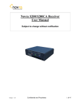
Novra S300N
DVB-S2 Satellite Data Receiver
User Manual
Subject to change without notification
Document version: 1.2
________________________________
Important-
Please read this entire manual before installing or operating this product.
________________________________
Disclaimer
While reasonable effort has been made in the preparation of this document to assure its accuracy, Novra
Technologies Inc. assumes no responsibility for errors or omissions that may appear in this manual. Novra
reserves the right to change the contents of this manual at any time without notice.
Copyright
© 2012 Novra Technologies Inc. All rights reserved.
Information in this manual is subject to change without notice. No part of this manual may be reproduced or
transmitted in any form without the express written permission of Novra Technologies Inc.
Version: 1.2
Confidential and Proprietary
2 of 40
INDEX
Page
1 Conventions .................................................................................................................................. 4 1.1 Text Conventions .................................................................................................................. 4 1.2 Applicable Models ................................................................................................................ 4 1.3 Model Naming Convention................................................................................................... 5 2 Introduction ................................................................................................................................... 6 2.1 Principles of Operation ......................................................................................................... 6 3 Getting Started .............................................................................................................................. 7 3.1 Typical S300 Installation ...................................................................................................... 7 3.2 What Information do I Need – Basic Configuration? ........................................................... 8 3.3 SOFTWARE Installation on Windows 7 .............................................................................. 9 3.4 S300 Startup ........................................................................................................................ 10 3.5 Main Screen ........................................................................................................................ 13 4 Configuring the S300 .................................................................................................................. 18 4.1 Interfaces ............................................................................................................................. 18 4.1.1 Network Button............................................................................................................... 18 4.1.2 Satellite Button................................................................................................................ 19 4.2 IP Data ................................................................................................................................ 24 4.2.1 Content Button ................................................................................................................ 24 4.2.2 IP Re-Mapping Button .................................................................................................... 25 4.3 Control ................................................................................................................................ 28 4.3.1 Reboot Button ................................................................................................................. 28 4.4 File Drop Down .................................................................................................................. 28 4.5 Control Drop Down ............................................................................................................ 31 4.6 Help Drop Down ................................................................................................................. 32 4.6.1 Help ................................................................................................................................. 32 4.6.2 About............................................................................................................................... 32 5 Troubleshooting .......................................................................................................................... 33 6 Specifications .............................................................................................................................. 35 6.1 Receiver Characteristics...................................................................................................... 35 7 Industry Canada Compliance Declaration .................................................................................. 37 8 Minimum System Requirements................................................................................................. 37 9 Supplied Equipment .................................................................................................................... 37 APPENDIX Terms, Definitions, and Tidbits of Information……………………………….....38
Version: 1.2
Confidential and Proprietary
3 of 40
1 Conventions
1.1 Text Conventions
NOTE: Information in this box
will be Informative.
CAUTION: This information
will be quite important and
should not be ignored.
Text appearing in Courier font indicates characters to be typed in; e.g. type Shell indicates that
the word “Shell” must be entered exactly as it appears, with the first letter capitalized.
Text appearing in Bookman Old Style font indicates a directory path or filename; e.g. c:\Program
Files.
Text appearing in SMALL CAPS and CopperPlateGothic32bc font in an instruction indicates a button
that must be clicked, or a key that must be pressed, or a field that must be entered or a particular
screen; e.g. BUTTON indicates a button that must be clicked.
1.2 Applicable Models
This manual is applicable to the following Novra Receiver models:
Novra S300N – Enhanced DVB-S2/DVB-S satellite data receiver capable of receiving IP data,
NOTE: - Your Novra S300 Configuration Application may also be used to configure other
Novra receiver families such as the S75 and the S200. This manual does not specifically
cover the configuration of these receivers, although the commands are very similar.
Version: 1.2
Confidential and Proprietary
4 of 40
1.3 Model Naming Convention
This manual uses the S300 naming convention when referring to any one of the applicable S300 models (see
Section 1.2 above).
NOTE: - This manual covers all of the models listed in Section 1.2 above. The S300 Console
will automatically detect the receiver model and will gray out console tabs that are not
required to configure the receiver.
If the feature you are trying to configure is grayed out in the S300 Console, please contact
Novra Support (www.novra.com) to inquire about a firmware or hardware upgrade.
Version: 1.2
Confidential and Proprietary
5 of 40
2 Introduction
2.1 Principles of Operation
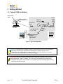
The S300 is a satellite receiver that enables the reception of IP and Video data carried on a DVB-S2 or DVBS compliant satellite signal.
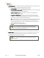
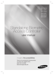
Please refer to Figure 1 below for a better understanding of the S300 operation. The desired DVB-S2 satellite
signal is received using an appropriately sized satellite dish (not covered in this manual). A Low Noise Block
(LNB) downconverter (not covered in this manual) is used translate the incoming Radio Frequency (RF)
signal to an Intermediate Frequency (IF) signal. The S300 receives this I/F signal and extracts the IP content,
which is then passed onto the S300 LAN for distribution or viewing via computers connected to the LAN. The
received data type may be IP data or may be MPEG video data, depending on the S200 model being
employed.
The S300 Management Console resides on a PC connected to the S300 via an Ethernet crossover cable or
through an Ethernet hub. The Console is used to perform the following functions:
Configure IP address network parameters,
Specify satellite tuning parameters,
Specify decryption parameters,
Select DVB information streams by Program IDentification number (PID), and
Map audio/video PIDs to multicast address(es).
Once configured, the S300 will retain its settings and continue to forward data transmitted to you by your
service provider even after restarting the S300 or your PC.
The S300 Receiver does not require a computer to continue operation. Once the configuration has been set,
you should have no need to change them.
Version: 1.2
Confidential and Proprietary
6 of 40
3 Getting Started
3.1 Typical S300 Installation
Received R/F
Signal
S300CA directly
controls/powers the
LNB
CAM Slot
(Optional)
Power
Supply
Received I/F
Signal
24 Vdc
(Center +ve)
Satellite Dish
and LNB
Installation
Disk
(Cat 5
Crossover
Cable)
Ethernet
Packets to/from
Mgmt Station
The S300
Receiver
Package
Figure 1: Typical Configuration
NOTE: - This information is needed in order for the receiver to function. It is recommended
that all the information be collected before attempting to install the service. Novra
Technologies Inc. expects that end users, who wish to control the LNB with the receiver,
already have good understanding of satellite technology.
CAUTION: Nothing should be inserted between the S300 and the satellite dish except for a
surge suppressor. Cable TV Splitters, TVs, VCRs, and FM receivers are not designed for
connection to this portion of the network. It is very likely they will be damaged by the LNB DC
voltage generated by the S300
Version: 1.2
Confidential and Proprietary
7 of 40
3.2 What Information do I Need – Basic Configuration?
Before using the S300 configuration software to configure your receiver, you need to gather the
following information:
in MHz of the stream you wish to receive.
1) The LO Frequency
NOTE: Local Oscillator Frequency is specific to the LNB Model and is usually stamped
on the Unit or can be found in the LNB Manual. Typical Ku Band values include: 9.75,
10.60,10.75, 11.00, and 11.25 GHz. For the C Band satellite frequencies a typical
value is 5.15 GHz.
2) The RF Band Frequency
in MHz of the stream you wish to receive. Your
satellite service provider should be able to provide this information for you.
3) Polarization: Horizontal / Left ____(+15, 18 or 20 Volts DC) OR Vertical / Right_____(+11, +13, or
20 Volts DC). Your satellite service provider should be able to provide this information for you.
NOTE: If the LNB does not have the ability to switch polarizations, choose a value that
will provide the most suitable power supply voltage. In most cases this will be
Horizontal / Left (+18 Volts).
4) Will the receiver be controlling a Single Band LNB (Most Common) or a Universal Band / Dual
LNB?
NOTE: The 22 KHz (or 44 KHz) tone is used to switch between the 2 bands of the
LNB. The receiver should be configured so that the proper tone is used and the proper
band is selected.
5) The Symbol Rate in Msps.
Examples: 21.096, 5.12600, 1.50, …etc.
6) The IP Address to be assigned to your Novra S300 Receiver
Example: 192.168.170.125
7) The IP address of the Default Gateway for the receiver.
8) Is the receiver supposed to filter multicast traffic using IGMP?
NOTE: IGMP is an Internet standard that is used to control multicast traffic on the LAN
based on the client’s interest in the stream. For proper operation, all components of
your network should support IGMP
Version: 1.2
Confidential and Proprietary
8 of 40
3.3 SOFTWARE Installation on Windows 7
The S300 Console software is supplied as a single executable. Therefore, it is easy to install on
different systems. All you need to do is copy the executable to your working directory.
Please refer to Section 8 for information on supported Windows Operating Systems.
NOTE: - You MUST be logged onto the system as Administrator.
NOTE: - Your screen resolution MUST be at least 800 x 600 and at least
"16 bit color" to function properly.
Version: 1.2
Confidential and Proprietary
9 of 40
3.4 S300 Startup
1- Start the S300 Console software.
NOTE: - You MUST be logged onto the system as Administrator, for the
network settings function to work properly.
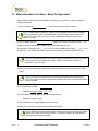
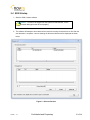
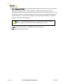
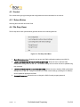
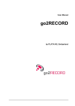
2- The software will attempt to auto-detect all the receivers currently connected to the LAN. After the
auto detection is complete, a screen showing all discovered devices will be displayed as shown
below:
Figure 2 - Discover Devices
Version: 1.2
Confidential and Proprietary
10 of 40
You can now select the device you wish to configure by double clicking on the receiver model type in
the Devices Discovered listing.
If there is an S300 receiver accessible on your network, but not on your local LAN you can still
configure it as if it were on your local LAN. In the Managed List section of the screen above, enter
the IPE address of the receiver you wish to configure in the IP field. You can also provide an optional
name beside it if you wish. Once the IP address is entered, click Add to add the IP address to the
Managed List. Now double click the IP address you just added to run the Configure Application on
the receiver. You can use the Add, Delete, and Delete All buttons to add/remove entries in the
Managed List.
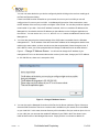
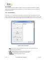
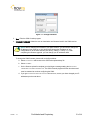
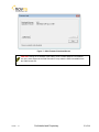
3- You must also ensure that the network settings of the S300 make it accessible from the Windows
management PC. The IP address of the device and the IP address of the management station must
reside on the same subnet, or there must be a route that connects both of them through a router. If
this is NOT the case, you will be prompted with the Change IP Address Screen as shown below in
Figure 3 – Change IP Address Screen. You will need to change the IP address of your
management PC to be on the same subnet as the receiver (in this case, change your PC IP address
to: 192.168.254.xxx, where xxx is not equal to 242).
Figure 3 – Change IP Address Screen
4- You can also use the Managed List section of the Device List Screen (reference Figure 2 above) to
direct the S300 Console to connect to a receiver that is available on your network, but not available
on your local LAN. In this case, the auto discovery will not be able to find your receiver (since it is not
on your LAN), but you can enter the routable IP address of your S300 in the IP box shown in the
lower left hand corner of the Managed List screen. Simply click the Add button to add this IP
Version: 1.2
Confidential and Proprietary
11 of 40
address to your Managed List and then double click on the IP address to initiate the log in procedure
with your receiver.
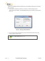
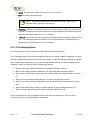
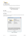
5- Once you have successfully connected to your receiver, you will be prompted to enter a
password (see Figure 4 below). The default password that you can use with your new receiver is:
Novra-S2.
Figure 4 – S300 Login Password Screen
6- After successfully entering the password, you will be presented with the S300 Console main
screen (as shown in Figure 5 below).
NOTE: - Default Password is Novra-S2
Version: 1.2
Confidential and Proprietary
12 of 40
3.5 Main Screen
Congratulations, you have logged into the receiver and made it to the main screen.
Your S300 DVB receiver supports both DVB-S and DVB-S2 modes of operation. From a receiver
configuration perspective, there are only a few differences between DVB-S mode and DVB-S2 mode. The
examples below were taken in DVB-S mode. Where applicable, the DVB-S2 specific configuration or status
items are highlighted below.
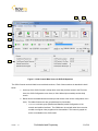
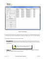
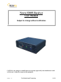
Figure 5 shows a typical Main Screen setting when the S300 is operating in DVB-S2 mode. The screen
provides configuration tabs as well as status information on the S300 operation. At a glance, we can
determine a great deal about the status of the S300 operation, including:
The console is receiving status from the S300 (status LED),
The receiver is locked (Signal LED) to a 13.086 Msps signal with a C/N of 31.5 dB.
The LNB DC voltage is turned on (LNB LED),
The S300 is receiving and processing valid DVB data (Data LED)
The input signal strength is good at -36 dBm
The S300 is demodulating a DVB-S2 signal with a modulation of 8SK and a coding rate of 3/5
At the present, the received signal quality is good with a BER of 0.0E0.
The receiver has received no uncorrectable packets. If this counter is moving, it is an indication that
the satellite link may not be good enough to maintain a solid lock.
Version: 1.2
Confidential and Proprietary
13 of 40
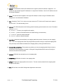
5
6
I
2
3
4
7
Figure 5 - S300 Console Main Screen for DVB-S2 Operation
The S300 Console can be divided into several basic sections. Each of these sections is described in detail
below:
1. At the top of the S300 Console is a drop down menu that provides access to the File menu
items, the S300 Configuration menu items, a Video Wizard (some models) and the Help
screen.
2. Below this are the tabbed buttons that also provide access to the various configuration menu
items. The tabbed buttons are also grouped based on functionality.
i. Interfaces button group (Network and Satellite) enable configuration of the
network and satellite interfaces. The CAM button is used with other Novra receiver
models to configure video programs to be descrambled. This button is grayed out
and is not available on the S300 model.
Version: 1.2
Confidential and Proprietary
14 of 40
ii. IP Data buttons enables the operator to configure the receiver to receive MultiProtocol Encapsulation (MPE) data and pass/map this data onto the LAN.
iii. A/V Data button group (Content and PAT) provides standard and advanced
features enabling the operator to receive MPEG transport stream packets and pass
these packets to Multicast IP addresses on the LAN. This functionality is not
available for the S300N and these buttons are therefore grayed out.
iv. Control button group provides an additional configuration item that includes
Reboot.
NOTE: - Typically the IP Data function is used to configure the S300 to receive
and re-distribute IP data, while the A/V Data function is used to configure the
to receive and re-distribute video programs. The AV Data function is not
available on your S300N receiver model.
3. The middle bar of this screen displays the IP address and MAC address for the selected
S300 being configured.
4. Status information on the operation of the S300 is provided in the lower part of the screen.
This status includes:
i. Status – Turns green when the status packets are being successfully received from
the S300 by the S300 console.
ii. Signal – Turns green when the receiver detects an input RF signal at the selected
frequency. This matches Signal LED on the front of unit.
iii. Data – Turns green when the S300 has achieved data lock. This means that the
receiver is able to recover all the digital timing from the input signal and is receiving a
valid DVB transport stream. This does NOT match the blue data LED on the front of
the S300.
NOTE: - S300 DATA LED – The blue data LED on the front face plate of the
S300 will blink at a ½ second interval if data is being processed and forwarded
by the S300.
iv. LNB – Turns green when the LNB is turned on and is gray when the LNB is turned
off. The LNB status LED will also turn red if there is a DC short present on the RF
connector input.
v. Signal Strength – Provides a graphic indication of the signal power at the input
of the receiver. The signal strength is shown as both a bar graph and percentage
strength.
vi. ModCod/Coding Rate : Depending on the mode of operation (DVB-S vs. DVBS2), this status value will change as follows:
Version: 1.2
Confidential and Proprietary
15 of 40
1. MODCOD (DVB-S2): Provides the modulation rate and coding rate of the
input stream; this number is only valid when the receiver is locked
2. Coding Rate (DVB-S): Indicates the Viterbi code rate of the input stream.
This number is only valid when the receiver is locked.
vii. PER/BER: Depending on the mode of operation (DVB-S vs. DVB-S2), this status
value will change as follows
1. PER (DVB-S2): Provides a count of the Packet Error Rate (PER).
2. BER (DVB-S): indicates the receiver Viterbi Bit Error Rate (BER) of the input
stream. This number is a true measure of the signal quality
viii. Uncorrectables –. The number of uncorrectable packets that were processed
by the demodulator section of the receiver. The counter accumulates and can be
reset using the Reset button located beside the Uncorrectables field.
ix. Carr. Freq. – Provides the I/F carrier frequency in Mhz and the difference between
the desired IF frequency and the tuned value.
x. Sym. Rate – Provides the receiver symbol rate.
xi. C/N – Provides the receive signal Carrier-to-Noise ratio (C/N).
5. Minimize – To the system Tray
6. Close – Close the S300 Console
7. Traffic Counters – The S300 provides a number of traffic counters that are useful in
determining the health and operation of the receiver. The description of the counters is
provided below:
i. Total Ethernet Packets Sent: This counter accumulates the total number of
packets being sent from the Ethernet port on the receiver.
ii. Total Ethernet packets received: The number of Ethernet packets that the
S300 received on the Ethernet interface.
iii. Ethernet Receive Errors: The number of errors that occurred during the
reception of Ethernet packets.
iv. Ethernet packets Dropped: the number of packets that the S300 couldn’t
transmit due to lack of buffers, or irresolvable address.
v. DVB Packets Accepted: The number of DVB packets that the receiver accepted
and processed.
vi. DVB Packets Descrambled: The number of clear or descrambled DVB packets
that the receiver accepted.
vii. DVB Packets Not Descrambled: The number of scrambled DVB packets that
the receiver accepted.
viii. DVB packets with bad Sync: Number of packets that didn’t have a proper
synchronization byte.
Version: 1.2
Confidential and Proprietary
16 of 40
NOTE: The counters will keep accumulating as long as the window is open.
You can use the reset buttons to reset the counters
Version: 1.2
Confidential and Proprietary
17 of 40
4 Configuring the S300
This chapter discussed how to configure the S300. It covers both the drop down menus as well as the
configuration buttons.
NOTE: When editing field lists (such as PID lists), you can often edit or delete the list
entries by right clicking on them.
NOTE: Pressing Esc on the keyboard when configuring the S300 has the same effect
as selecting Exit.
4.1 Interfaces
The Interfaces group of buttons enables the operator to configure the 3 key interfaces on the S300, namely
the LAN or Network interface, the Satellite or L-Band interface, and the CAM interface. These are all
discussed further below.
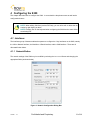
4.1.1 Network Button
The network settings of the S300 may be modified by selecting the Network Button and changing the
appropriate fields (as shown below).
Figure 6 - Network Configuration Dialog Box
Version: 1.2
Confidential and Proprietary
18 of 40
1. Receiver IP: This is the IP address to be assigned to the receiver.
2. Subnet Mask: This is the subnet mask that the receiver should use to determine whether an IP
address belongs to the same network or not.
3. Default Gateway: This is the IP address of the router that the receiver should use whenever it
wants to send traffic to a non-local address.
4. Enable IGMP Filtering: This check box allows the operator to turn IGMP filtering on or off.
IGMP controls which multicast streams will be forwarded on the LAN based on the number of
clients listening to that stream.
NOTE: - Proper operation of IGMP protocol requires that all devices used in the
network support IGMP protocol.
5. Status Destination Port: This is the UDP port used to send a copy of the status packets for
remote monitoring applications
6. Status Destination IP: This is the IP address used to send a copy of the status packets for
remote monitoring applications
NOTE: - To turn off the status packets being sent to a unicast destination IP
address, set the Status Destination IP to 255.255.255.255.
7. Apply: By pressing this button, the updates are sent to the receiver
8. Exit: Exits back to the main screen
NOTE: The Device status can be sent to a remote management station by
configuring the status destination IP and port. However these settings don’t affect
the broadcast status messages. To turn off the unicast status, set the destination
IP address to 255.255.255.255
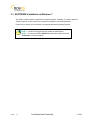
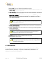
4.1.2 Satellite Button
The next step in the configuration is to ensure you have the correct RF settings and that the S300 can
successfully lock to your satellite signal. To configure your satellite settings, select the Satellite
configuration button and input the following fields:
Version: 1.2
Confidential and Proprietary
19 of 40
Figure 7: Satellite Configuration and LNB Parameters Dialog
1) Receive Frequency: The RF Frequency of the signal that you are trying to receive.
2) Symbol Rate: This is the symbol rate of the transponder that you are trying to tune to. The S300
supports automatic detection of the incoming symbol rate (check box) or you can manually specify
which symbol rate you wish the receiver to tune to.
3) Gold Code: Enter the Gold Code setting here. This must match the Gold Code setting in the
modulator that is used to generate the DVB-S2 stream. For DVB-S operation, the Gold Code box
will be grayed out.
NOTE: - If the Search Mode is set to Both and the received stream is DVB-S,
then the contents of the Gold Code box will be ignored by the receiver.
Version: 1.2
Confidential and Proprietary
20 of 40
4) ModCod: For multi-stream DVB-S2 operation, the S300 should be configured to receive 1 stream.
This is accomplished by entering the ModCod of the signal you wish to receive in the ModCod drop
down box. If you enter the wrong ModCod value, you receiver may not be able to lock onto the
desires signal.
For single stream DVB-S2 operation, the Modcod dropdown should be set to All. For DVB-S
operation, the Modcod box will be grayed out.
NOTE: - If the Search Mode is set to Both and the received stream is DVB-S,
then the contents of the ModCod box will be ignored by the receiver.
5) LNB Power On: Turns the DC voltage and tone output of the receiver to ON or OFF.
a. Polarization: Switches the DC output of the receiver between Horizontal/Left and
Vertical/Right. This setting is only valid if the LNB power is on.
NOTE: - The LNB voltage level may be set by selecting the LNB Parameters
button.
b. Band (Tone): Switch the LNB Tone frequency of the receiver On (High) or Off (Low). This
is only valid if the LNB power is on.
NOTE: - The LNB tone frequency may be set by selecting the LNB Parameters
button.
Version: 1.2
Confidential and Proprietary
21 of 40
6) LNB Parameters: Click this button to bring up the LNB Parameters screen. It is used to set the
LO frequency, polarization voltage and LNB tone (see Figure 7 above):
a. LO Frequency: Input the single-band LO frequency in Mhz.
b. Polarity Switching Voltage: Select either 11-15 Volts, 13-18 Volts or 21 Volts for the
Vertical/Right and Horizontal/Left LNB voltage values.
c.
High/Low Band Tone: Select either 22 KHz or 44 KHz for the LNB switch tone
frequency. Typically 22 KHz is used.
d. Long Line compensation: Checking this box will increase the Polarity Switching
voltage by 1 V. This additional voltage may be used to compensate for the voltage drop
due to a long I/F cable run between the S300 and the LNB.
e. OK: By pressing this button, the screen updates will be temporarily stored and the user will
be returned to the Satellite screen. By selecting Apply on the Satellite screen the LNB
Parameter settings will be sent to the S300. Selecting Exit will exit the Satellite screen
without setting the LNB Parameter updates.
f.
Cancel: Exits back to the satellite dialog screen
NOTE: - If a dual LNB is being deployed, ensure that the appropriate LO
frequency is entered in the LO Frequency box and that the correct band
(high or low) is selected in the Satellite screen.
7) Search Mode: Select either the DVB-S2, DVB-S or Both radio button to set your receiver to
receive a DVB-S2 or DVB-S compliant satellite signal. If you select Both, the receiver will
automatically select the correct mode of operation
NOTE: - The S300 can automatically select between DVB-S2 and DVB-S
input streams.
Version: 1.2
Confidential and Proprietary
22 of 40
8) Input Stream ID Filter: The Input Stream Identifier (ISI) Filter may be used by your receiver to
filter streams based this value. If the ISI checkbox is selected, then the receiver will only
demodulate streams that have an ISI value that is the same as the value shown in the ISI box. This
command should only be used if the ISI stream value is set on the incoming DVB-S2 stream and if
the ISI value is know. You may have to contact your uplink provider for assistance. For DVB-S
operation, the ISI input will be grayed out.
NOTE: - If the Search Mode is set to Both and the received stream is DVB-S,
then the contents of the ISI Filter box will be ignored by the receiver.
9)
Apply: By pressing this button, the updates are sent to the receiver.
10) Exit: Exits back to the main screen
Version: 1.2
Confidential and Proprietary
23 of 40
4.2 IP Data
The IP Data group of buttons enables the operator to configure the reception and transmission of MPE IP
data. This group includes two buttons: the IP Data Content button and the IP Remap button. Both are
described in detail below.
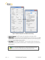
4.2.1 Content Button
The IP Data Content button screen (shown below) is used when the S300 is to be configured to receive
MPE or IP data from the satellite stream and forward this data to the appropriate IP address on the LAN. This
screen is used to add (or delete) the data Program IDs (PIDs) that enable the S300 to receive the IP content.
Figure 8: IP Data Content PID's
1. PID: Use this edit box to add a new Program ID to the list; you can use decimal input or
hexadecimal values preceded by “0x”.
2. ADD: This button adds the content of the PID box to the PID List.
3. Delete: This button deletes the selected PID from the PID list.
4. Delete All: This button will empty the PID list.
Version: 1.2
Confidential and Proprietary
24 of 40
5. Apply: By pressing this button, the list will be sent to the receiver.
6. Exit: Exits back to the main screen
NOTE: - The keyboard may be used to add and remove PIDs. Also, to edit or
delete the PID list, right click on the list entry
7. Pass All: Selecting this checkbox will pass the full MPEG transport stream (less null packets) to
the LAN. The transport stream will be passed to the multicast destination IP address/port that is
entered in the field just below the Pass All checkbox
8. + Nulls: Selecting this checkbox will pass the full transport stream including null packets to the
LAN. . The transport stream will be passed to the multicast destination IP address/port that is
entered in the field just below the Pass All checkbox
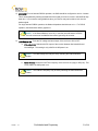
4.2.2 IP Re-Mapping Button
This section discusses how to configure the IP Re-Mapping feature within the S300.
The IP Remapping feature in the S300 will enable the operator to re-map a multicast IP addresses or multiple
multicast IP addresses that have been received by the receiver to a different destination multicast IP address.
The IP mapping table will support up to 16 entries and will therefore allow for 16 multicast addresses to be
remapped. Some of the features of the IP mapping table include:
Ability to map single multicast IP address to a destination multicast IP address
Ability to map multiple multicast IP addresses to a single destination multicast IP address,
Ability to use a subnet mask to map a range of multicast IP address to a single destination multicast
IP,
Ability to turn the multicast mapping table on or off without losing the table contents,
Ability to turn a single multicast mapping table entry off (No Rule) without losing the entry from the
table,
Ability to use IGMP filtering to enable (or disable) sending of mapped multicast packets, and
Ability to forward mapped multicast IP packets regardless IGMP filter setting
The IP mapping table can only be assessed from the main screen by selecting the IP Remap button.
This will bring up the IP re-mapping table as shown below.
Version: 1.2
Confidential and Proprietary
25 of 40
Figure 9 - IP Remapping
Referring to the figure above, the left hand side of the screen enables you to configure the mapping rules and
the right hand pane summarizes and displays the configured IP mapping rules. Up to 16 rules are supported.
The following is a description of the above screen entries:
1) Enable Mapping: Check this box to enable the mapping table. Unchecking this box can also be used
to disable the entire mapping table without losing the table contents. The table can then be re-enabled by
checking the box.
NOTE: The Enable Mapping box must be
checked to use the IP Mapping feature
2) Original IP: The original multicast IP address that is to be mapped to a new destination IP address.
Note: This IP address must be a multicast IP address.
Version: 1.2
Confidential and Proprietary
26 of 40
3) New IP: The destination multicast IP address that the original multicast IP address is mapped to. It is
possible to map multiple Original IP addresses to a single New IP address. Note: this IP address must be
a multicast IP address.
4) Mask: The subnet mask is applied to the Original IP address to create a range of IP address that is
mapped to the new destination IP address.
5) TTL: Setting the Time To Live value to non-zero causes the TTL field in the IP header to be replaced
with this value. The default setting is zero.
6) Action: The S300 shall perform the following packet forwarding options based on this value. The default
setting is no rule.
a) No Rule - rule entry is not applied to the packet
b) Normal - packet is forwarded based on the IGMP setting (see Note below)
c) Forward - packet is always forwarded
d) Discard - packet is always discarded
7) Add Rule: Adds the rule as defined by the mapping table fields (entries 2-6 above) into the mapping
table. Note: The mapping table fields may be populated by double clicking on a selected mapping table
entry and may be then edited and added to the mapping table by clicking the Add Rule box.
8) Change Selected Rule: The operator may load any rule into the mapping table fields (2-6 above)
and edit any of the parameters as needed. Clicking the Change Selected Rule button will modify the
selected rule with the edited updates.
9) Delete: Will delete any selected entry in the mapping table
10) Delete All: Will delete all entries in the mapping table
11) Apply: Will apply the mapping table to the receiver. This box must be selected for the mapping table
changes to take effect
12) Exit: Will exit back to the S300 Configuration Application main screen
Version: 1.2
Confidential and Proprietary
27 of 40
4.3 Control
The Control button group provides general configuration and control elements for the receiver.
4.3.1 Reboot Button
Selecting this button will reboot the S300.
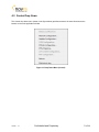
4.4 File Drop Down
The file drop down menu (shown below) provides access to the following features
Figure 10 - File Drop down Menu
1. Save Configuration: Allows the user to save the S300 configuration settings to an XML file
2. Load Configuration (without network settings): Allows the user to load the S300
configuration settings from an XML file. The network settings of the receiver will not be updated using
this command.
3. Load Configuration (with network settings): Allows the user to load the S300 configuration
settings from an XML file. Using this command, the S300 network settings (including the IP address)
will be updated an applied to the S300.
4. Change Password: Allows the user to change the S300 Console program password.
Version: 1.2
Confidential and Proprietary
28 of 40
Figure 11 - Change Password
5. Exit: Exits the S300 Console program
6. Change Firmware: Allows the user to download a new firmware load for the S300 receiver.
NOTE: Before changing the firmware in your S300 receiver, you will need to change the
IP address of your receiver to 192.168.0.x AND change the IP address of your
configuration PC to the same subnet (192.168.0.y, where y ≠ x and y ≠ 1). After
completing the firmware upgrade, you can change your IP addresses back.
To change the S300 firmware, please refer to the figure below:
a. Select Code File and browse to the S300 code update binary file.
b. Select Commit.
c.
On the firmware upload is complete you should get a message stating the Receiver
firmware has been rewritten. The S300 Console program will then shut down and
must be restarted to continue configuring the S300.
d. If you get a Code Download Failed timeout error, ensure your have changed your IP
addresses per the note above.
Version: 1.2
Confidential and Proprietary
29 of 40
Figure 7 - S300 Firmware Download Screen
CAUTION: Setting the IP address of the S300 to a non-routable address or an address
not on the same subnet as the S300 Console PC may make the S300 unreachable from
the S300 Console PC.
Version: 1.2
Confidential and Proprietary
30 of 40
4.5 Control Drop Down
The Control drop down menu (shown in the figure below) provides access to the same functions as the
buttons on the main application window.
Figure 13: Drop Down Menu (Control)
Version: 1.2
Confidential and Proprietary
31 of 40
4.6 Help Drop Down
The Help drop down menu provides access to the Help menu and the About menu.
Figure 14 - Help Drop Down Menu
4.6.1 Help
The Help menu is not currently available.
4.6.2 About
An example of the About menu is shown below. It provides Novra contact information and the receiver
hardware and software version numbers.
Figure 15 - About Screen
Version: 1.2
Confidential and Proprietary
32 of 40
5 Troubleshooting
This section can help you resolve most of the common problems when installing the S300.
1) I connected the receiver and when I start the Console, it says it can’t detect any S300 Receivers?
-
Make sure the unit is connected to the same LAN that your computer (running S300 Console) is
connected to. The best way to rule that out is to use a cross over cable.
-
Make sure the unit is powered up and the Ethernet link is established. The green LED on the back of
the Ethernet connector should be on solid, and the yellow light should be blinking.
-
If you are using a hub, make sure there is only one unit connected.
2) I connected my unit, and it was auto detected. Every time I try to configure the device I get an
error Message. What could be wrong?
-
Make sure the IP address assigned to the receiver is reachable from your PC, and the receiver is
configured correctly to reach your machine (try pinging the receiver from your PC).
3) Why won’t the receiver lock to my settings?
-
Is the RF cable connected?
-
Are you using the correct RF Settings (frequency and symbol rate)?
-
Are you using the correct voltage/tone settings for the LNB?
4) The receiver is locked to my signal and there is no Data, why?
-
Do you have the right PID selected?
-
Are you sure you are on the right transponder?
-
If the Ethernet Transmitted packet counter is counting up. Use program such as Wireshark to
determine where the traffic is going?
-
Is the default gateway on the receiver set correctly?
-
Does the DVB MAC address of the traffic match the Mac address of your unit? (UNICAST)
-
Are you using IGMP and the network clients are not subscribing? (multicast)
-
Is the IGMP hardware filtering checked off (in the Network tab), but no network clients subscribing
with IGMP join requests.
5) I have created a mapping rule, but the packets don’t seem to be mapped. I only see the original
IP packets when I sniff the LAN.
-
Make sure you have enabled the Mapping table,
-
Make sure your mapping action rule is Normal or Forward,
Version: 1.2
Confidential and Proprietary
33 of 40
6) I have created a mapping rule, but the packets don’t seem to be mapped. I don’t see either the
Original IP packets or the New IP packets when I sniff the LAN.
-
Make sure your mapping action rule is Normal or Forward,
-
If your mapping action is Normal and you have IGMP filtering enabled, make sure you have an
application running that will generate an IGMP join to receive the packets. Otherwise you could try to
turn IGMP filtering off, or set your mapping action rule to Forward. Note: if you set your mapping
action rule to No Rule, the Original IP packets will not get mapped and the IP traffic on your LAN will
be your Original IP packets.
7) I am trying to update the firmware, but I keep getting a Code Download Failed timeout
error?
-
Try changing the IP address of your receiver to 192.168.0.x and change the IP address of your
configuration PC to the same subnet, such as 192.168.0.100. Do not use 192.168.0.1 or the same IP
address as your S300.
Version: 1.2
Confidential and Proprietary
34 of 40
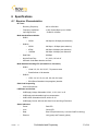
6 Specifications
6.1 Receiver Characteristics
RF Tuner
-
Receiving Frequency:
950 to 2150 MHz
-
Frequency Acquisition:
± 50% Symbol Rate up to ±10 MHz
-
Input Signal Level:
-70 dBm to -25 dBm
Multi-standard Demodulation
-
DVB-S
o
-
QPSK:
300 Ksps to 45 Msps (auto selection)
DVB-S2
o
QPSK:
600 Ksps - 45 Msps (auto selection)
o
8PSK:
600 Ksps -30 Msps (auto selection)
o
16APSK
600 Ksps -30 Msps (auto Selection
-
Data Rate:
80 Mbps
-
Nyquist Root Filter:
0.2, 0.25, 0.35 roll off
-
Automatic Code Rate detection and lock
Multi-Standard Decoding FEC (Forward Error Correction)
-
-
DVB-S
o
Viterbi 1/2, 2/3, 3/4, 5/6, 6/7, 7/8 puncture rates
o
Reed Soliman 16 bit decoder
DVB-S2
o
LDPC 1/2, 3/5, 2/3, 3/4, 4/5, 5/6, 8/9, 9/10 rates
o
BCH (Bose-Chaudhuri-Hocquenghem) decoder
Gold Code Sequencing
-
0-26143 Sequences
LNB Power and Control
-
LNB Supply Voltage: Selectable 13/18V, 11/15V, 20 V or off
-
LNB Supply with selectable long line compensation
-
LNB Control: Selectable 22 KHz, 44 KHz or off
-
LNB Supply Current: 400 mA with Short Circuit and Surge Protection
Status Indicators
Version: 1.2
-
Power:
Red LED
-
Lock:
Green LED
-
Data:
Blue LED (will blink every ½ second if traffic is flowing)
-
Ethernet
Link (green) and Transmit (yellow)
Confidential and Proprietary
35 of 40
Hardware Capabilities
-
Multiprotocol Encapsulation (MPE)
-
PID Filters: 32
-
Internal Hardware Watchdog
-
Non-Volatile Configuration Storage
-
Field upgradeable operating system for new s/w releases and functional upgrades
Operating Systems
-
Once Configured, Receiver Supports all Operating System
Physical Interfaces
-
RF Input Connector:
F-Type, 75 ohms
-
Ethernet 100 Base-T LAN Interface:
RJ-45
CAUTION: Nothing should be inserted between the S300 and the satellite dish except for a
surge suppressor. Cable TV Splitters, TVs, VCRs, and FM receivers are not designed for
connection to this portion of the network. They will not work and if they are connected, even for a
brief moment, they will probably never work again because the power on the coax will destroy
the input of the misplaced unit.
Version: 1.2
Confidential and Proprietary
36 of 40
7 Industry Canada Compliance Declaration
This Class B digital apparatus complies with Canadian ICES-003.
Cet appareil numérique de la classe B est conforme à la norme NMB-003 du Canada.
8 Minimum System Requirements
Your computer must operate with any one of the following operating systems to successfully use the
Novra Receiver:
Windows 7 Ultimate
-
Note: To start the application on Windows 7 Home Premium or Windows 7
Professional, you may have to right click on the application and select “Run as
Administrator”.
Other Versions of Windows, such as XP, 2000 or Vista will most likely work with Novra
Configuration Application, but this has not been verified by Novra.
NOTE: - Performance will be dependant on other applications that your PC is running.
9 Supplied Equipment
Please confirm you have received all the equipment listed below.
Novra S300 Receiver
Cross-over cable or Ethernet cable
Power supply (120 Vac to 24 Vdc North America; OR 220 Vac to 24 Vdc European)
S300 Receiver Software CD
Novra S300 Receiver User Manual (Soft Copy on CD)
Version: 1.2
Confidential and Proprietary
37 of 40
APPENDIX
Terms, Definitions, and Other Tidbits of Information
Crossover Cable
A crossover cable is a cable that is used to connect two computers by reversing, or
crossing over, the cable pin contacts. This eliminates the need to use a hub when
connecting two PCs. It is also referred to as a "Null Modem" cable.
Coax Cable
Looks like this:
The coaxial cable is most commonly used for Cable TV feeds inside a house or
apartment. This form of cable allows the high frequencies of TV, and Satellite type
signals to move from one place to another with a minimal amount signal loss.
DVB
Digital Video Broadcasting (DVB) is a set of standards that define digital broadcasting
using satellite, cable, and terrestrial infrastructures.
FEC
Forward Error Correction (FEC) is a system of error control for data transmission
where the receiving device can detect and correct certain errors.
Feed Horn
This is the device that receives the focuses signals from a satellite dish. It collects
these signals and submits them to the next piece of equipment in the network, usually
a Low Noise Block converter which then changes the signals into a better format for
transpiration to the receiver.
Geostationary Orbit The position where a satellite is 35,786 kilometers (22,241 miles) above the equator.
At this distance, the satellite Orbits the earth at the same rate as the earth is turning.
This causes the satellite to appear stationary in relation to an observer on the ground.
IP
The Internet Protocol (IP) is a network communication protocol used on Ethernet
networks and the Internet.
IP Address
The 32-bit computer address defined by the Internet Protocol. It is usually represented
in dotted decimal notation. Example: 192.168.111.112
L-Band
This range of frequencies is from 950 MHz to 2,150 Mhz It is much lower than those
used by satellites (About 1/10 to 1/6). Satellite frequencies travel well through space
and our atmosphere but do not do well through the cable that comes from the dish on
the roof to the receiver. So LNBs convert satellite frequencies to the lower, easier to
transport, band of frequencies referred to as the L-Band. It is L-Band frequencies that
the S300 receiver tunes to.
LNA
Older systems used a unit called an LNA Low Noise Amplifier. This unit amplifies the
RF frequency and then transmits the signals down a special (expensive) cable to the
receiver. Note that received signals are not converted to lower frequencies by this unit.
LNB
LNB stands for a Low Noise Block-converter. This unit receives the signals collected
from a satellite and converts their very high frequencies (12 Giga Hertz, written 12
GHz, which is actually 12,000,000,000 cycles per second) to a lower and somewhat
more usable range. All LNBs have a Local Oscillator (LO). This number is usually
stamped on the LNB but not always. It may be necessary to check the original
Version: 1.2
Confidential and Proprietary
38 of 40
specifications that came with the LNB or use the model number and brand name to
search the Internet.
LNBF
LNBF stands for a Low Noise Block-converter and Feed horn. This is quite a common
arrangement where the Feed Horn focal point that collects reflected signals from the
satellite dish is combined with the low noise block-converter into one package.
LO
The Local Oscillator (LO) is a circuit that creates a tone of a very specific frequency.
These units have many applications in electronics. This important thing to remember is
that there is an LO in the LNB (Low Noise Block-converter) and it is part of the circuit
that converts the received satellite RF Frequencies to the more user friendly L-Band
Frequencies. Typical values include 9.75, 10.60, 10.75, 11.00 and 11.25 GHz for the
Ku band and 5.15 GHz for the C Band of satellite frequencies.
MAC Address
The Media Access Control (MAC) address is the unique hardware address for any
piece of electronic equipment attached to a network. The MAC Address for your Novra
S300 Receiver is displayed on a sticker on the bottom of the receiver.
Mbps
Mega bits per second. (Million bits per second)
MBps
Mega Bytes per second. One "Byte" in computer terms is the same as 8 bits. It is often
referred to as a word.
1 Mbps = 8 Mbps = 1 million Bytes (Words) per second = 8 million bits per second.
Msps
Mega symbols per second. Suppose you have four symbols, call them A, B, C & D.
Let the Symbol A represent two bits of data with the value 00.
Let B represent two bits of data with the value 01
Let C represent two bits of data with the value 10
Let D represent two bits of data with the value 11
This means that if the signals we are interested in consist of 1.0 Msps (That's 1 Million
symbols per second), and each symbol represents two bits of data, then our signal
has a data rate of 2.0 million bits per second (2.0 Mbps).
The important point to remember is that satellite systems send and receive symbols
which are then converted into data. The S300 takes the resulting data and forwards it
to your computer in bursts called "packets."
Packet
A packet is the unit of data that is routed between an origin and a destination. When
any file is sent from one place to another (the Internet as an example) it is divided into
"chunks" of an efficient size for routing. Each of these packets is separately numbered
and includes the Internet address of the destination.
PID
The Packet Identification Code (PID) is used by the receiver to sift through the
different packets of the transport stream. The transport stream contains data
representing many different signals. The S300 software running on your PC uses the
PID number to find only those packets of data that contain the information you have
requested. (See RF Frequency.)
Polarization, Circular In layman's terms, a circularly polarized signal corkscrews towards the earth.
(Right / Left)
Unlike linear polarization (described below), where the signal is fixed in an up and
down fashion or a side to side fashion, Circular Polarization causes the signal to
rotate. If it were possible to actually see the incoming signal, it would rotate like the
hands on a clock. As with Linear Polarization, this has two modes of operation. It can
Version: 1.2
Confidential and Proprietary
39 of 40
either rotate in a clock wise fashion or counter clockwise. Polarization is very useful
because it allows the frequency of a Right polarized signal to overlap with the same
frequencies of a Left polarized signal.
Polarization, Linear
(Horizontal/Vertical)
In layman's terms, a linearly polarized signal from a satellite approaches the
earth as a wave that goes up and down like the waves on the ocean, or from side to
side. These two types of waves are classified as being vertically or horizontally
polarized. Polarization is very useful because it allows the frequency of a vertically
polarized signal to overlap with the same frequencies of a Horizontally polarized
signal.
RAM
Random access memory. Used for short term storage of information requiring quick
access on a computer. Information stored in RAM can be accessed by the computer
much faster than information on the Hard Drive can be accessed.
RF Frequency
Each satellite in orbit has several channels that it can use, each with its own RF
Frequency. (Each channel is often referred to as a transponder.) The easiest way to
understand them is to think of your FM radio. There are many channels on the FM dial
that one can choose from. ("99.9 FM, All Rock, All the Time") When you input the
station number to your FM receiver you are actually telling it what RF Frequency it
should look at. (99.9 FM means that 99.9 Mega Hz is the desired frequency.) But
unlike the FM radio where the channel you tune to only contains one stream of music,
a satellite channel contains many individual signals. One channel can contain Internet
data and video and audio and specialized data in any number of permutations and
combinations. The S300 uses the PID numbers that come with each Internet data,
video, audio and specialized data signal to separate them all. (See PID.)
Satellite Signal Hierarchy
1 Satellite has |
10 - 24 Transponders (Channels) each with
|
dozens of distinct RF Frequencies each containing
|
up to a theoretical maximum of 8190 packet streams identified by their individual PIDs.
Subnet
A portion of a network, which may be a physically independent network segment, and
which shares a network address with other portions of the network.
Symbol Rate
See Msps
Transponder
This is the unit on the satellite that receives a signal transmitted from the earth station,
amplifies it, changes its frequency and retransmits it back down to earth. Each radio
channel has its own transponder and a number of transponders on the satellite are
used to cover the allocated frequency band. A typical satellite will have 24
transponders.
Viterbi
"Convolutional encoding with Viterbi decoding is a Forward Error Correction technique
that is particularly suited to a channel in which the transmitted signal is corrupted
mainly by additive white Gaussian noise." Further information can be found by
searching the Internet or looking at any of these sites.
http://pw1.netcom.com/~chip.f/Viterbi.html
http://hissa.nist.gov/dads/HTML/viterbiAlgorithm.html
Version: 1.2
Confidential and Proprietary
40 of 40