1
SATELLITE ROUTER
UHP-1000
USER MANUAL
SOFTWARE RELEASE 3.0
MAY 2013
UHP Software 3.0 User Manual
2
Table of contents
1. Glossary
2. Hardware overview and functions
2.1 Interfaces and controls
3. State analysis
3.1 Front panel indication
3.2 Faults
3.3 Events
4. UHP access for configuration
4.1 USB interface
4.2 Telnet interface
4.3 Default configuration
5. Command interface
6. HTTP interface
6.1 Introduction
6.2 Selection tree
6.3 Statistics frame
6.4 Main screen overview
7. Site setup
8. Profiles
8.1 Profiles basics
8.2 Profile running rules and profile operation states
8.3 Basic profile configuration
8.4 TDM/SCPC RX
8.5 TDM/SCPC TX
8.6 MODULATOR
8.7 TLC
8.8 ACM
8.9 TDMA RF
8.10 TDMA protocol
8.11 TDMA Timing
8.12 Crosspol RF
8.13 TDMA Bandwidth allocation
8.14 Return channel
9. Routing and Bridging
9.1 SVLAN overview
9.2 IP router
9.3 Routing Table
9.4 IP address
9.5 Static Route
9.6 TX map
9.7 VLAN Bridge
9.8 SVLAN Receive
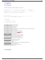
10. IP Protocols
10.1 SNMP
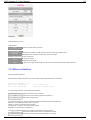
10.2 DHCP
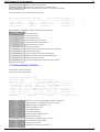
10.3 RIP
10.4 SNTP
10.5 RTP
10.6 TFTP
10.7 Multicast
10.8 Acceleration
10.9 COTM/AMIP
10.10 Other settings
11. QOS
11.1 Policies
11.2 Shapers
11.3 Real-Time
11.4 Service monitoring
12. Network
12.1 Network Overview
12.2 Stations
12.3 MF-TDMA
12.4 Statistics of ACM
12.5 SCPC TLC / NMS / Redundancy
12.5.1 SCPC TLC
12.5.2 NMS
Document version 1.0, May 2013
2
UHP Software 3.0 User Manual
3
12.5.3 Redundancy
13. System
13.1 Overview
13.2 Interfaces
13.3 Ethernet statistics
13.4 Demodulator statistics
13.5 Modulator statistics
13.6 Time-related
13.7 User access
13.8 Flash/Boot
13.9 Save/Load
14. Maintenance
14.1 Support information
14.2 Pointing
14.3 Network Command
14.4 Traffic generator
14.5 Reboot
Document version 1.0, May 2013
3
UHP Software 3.0 User Manual
4
1. Glossary
16APSK
8PSK
AGC
BCH
BUC
C/N
CCM
COTM
CRTP
DAMA
DSCP
DVB
Eb/N0
EIRP
ETSI
FEC
Hard priority
HTTP
Frame
Frame plan
HUB
Hubless
HW
ICMP
IESS
IFL
IGMP
16 Amplitude and Phase-shift keying or Asymmetric Phase-shift keying, (APSK), is a digital
modulation scheme that conveys data by changing, or modulating, both the amplitude and the
phase of a reference signal (the carrier wave).
Phase-shift keying (PSK) is a digital modulation scheme that conveys data by changing, or
modulating, the phase of a reference signal (the carrier wave).
Automatic Gain Control
BCH code is a multilevel cyclic variable-length digital error-correcting code used for correcting
multiple random error patterns. BCH codes may also be used with multilevel phase-shift keying
whenever the number of levels is a prime number or a power of a prime number.
Block Up-Converter is used in the transmission (uplink) of satellite signals. It converts a band (or
"block") of frequencies from a lower frequency to a higher frequency.
Carrier-to-noise ratio, often written as CNR or C/N, is the signal-to-noise ratio (SNR) of a
modulated signal.
Constant coding and modulation. DVB-S2 mode when MODCOD is not changed during channel
operation.
Communication on the move.
Compressed Real-time Transport Protocol, header compression of IP/UDP/RTP datagrams
reduces header overhead.
Demand Assigned Multiple Access. Channel establishment on demand.
Differentiated Services Code Point (DSCP) is a 6-bit field in the header of IP packets for packet
classification purposes. DSCP replaces the outdated IP precedence, a 3-bit field in the Type of
Service byte of the IP header originally used to classify and prioritize types of traffic
Digital Video Broadcasting (DVB) is a suite of internationally accepted open standards for digital
television.
Ratio of Energy per bit (Eb) to Noise density (N0).
Effective Isotropically Radiated Power.
The European Telecommunications Standards Institute is an independent, non-profit,
standardization organization in the telecommunications industry (equipment makers and network
operators) in Europe, with worldwide projection.
In telecommunication and information theory, forward error correction (FEC) is a system of error
control for data transmission, whereby the sender adds redundant data to its messages, also
known as an error-correction code.
Method of transmission queues handling when packets from lower priority queue are not
transmitted until all packets from higher priority queue are transmitted.
Hypertext Transfer Protocol (HTTP) is an application-level protocol for distributed, collaborative,
hypermedia information systems.
Sequence of time slot s. Number of slots is frame length . Repeated every ~100 ms while
assignment of stations to slots can vary every frame.
TDMA service packet describing which station should transmit in which time slot . Generated ~10
times per second.
Central Station of satellite network that is managing all the stations and resources
Special mode of operation when all stations are transmitting to one TDMA carrier and all
receiving this carrier.
Hardware
The Internet Control Message Protocol (ICMP) is used by networked devices to send error
messages indicating, for instance, that a requested service is not available or that a host or router
could not be reached.
Intelsat Earth Station Standards
Connection from the indoor equipment (modem/router) to the outdoor equipment at the antenna
normally involves two inter-facility (IFL) cables.
The Internet Group Management Protocol (IGMP) is a communications protocol used by hosts
and adjacent routers on IP networks to establish multicast group memberships.
Document version 1.0, May 2013
4
UHP Software 3.0 User Manual
Inroute
IP
LDPC
LNB
Local oscillator
Long frames
Master
MCPC
Mesh
MF-TDMA
MODCOD
NMS
Node
ODU
Outroute
QPSK
RSV
RF level
SCPC
Short frames
SNMP
SNTP
SNR
SR
Star
SW
TDM
TDMA
Telnet
TFTP
UDP
Timestamp
Time slot
5
Channel from stations to hub.
IP is the usual abbreviation for Internet Protocol.
Low-density parity-check (LDPC) code is a linear error correcting code, a method of transmitting
a message over a noisy transmission channel, and is constructed using a sparse bipartite graph.
Low-noise block converter installed at satellite antenna.
Oscillator built into RF block converter ( BUC or LNB ). Value of LO is usually written on block
enclosure or in datasheet.
DVB-S2 frames 64800 bits long (including FEC). Require slightly lower C/N than short frames .
Main station of hubless network. Master allocates bandwidth and performs stations acquisition.
Multiple channels per carrier. All TDM carriers generated by UHP can be treated as MCPC. Even
if they are called SCPC .
Capability of station allowing to receive other stations via TDMA link.
TDMA working on several RF channels simultaneously. All MF channels work as one aggregate
TDMA channel.
Modulation and coding mode of DVB-S2 transmission.
Network Management System
Station of satellite network which is able to receive information directly from other network
stations.
Out-Door Unit
Forward TDM channel from HUB to stations.
Phase-shift keying (PSK) is a digital modulation scheme that conveys data by changing, or
modulating, the phase of a reference signal (the carrier wave).
Concatenated Reed-Solomon/Viterbi FEC used in DVB-S1 standard.
Absolute RF level of entire signal (carrier + adjacent carriers) expressed in dBm.
Single Channel Per Carrier
DVB-S2 frames 16200 bits long (including FEC). Advisable to use at lower symbol rates.
Produce less delay than Long frames .
Simple Network Management Protocol
Simple Network Time Protocol (SNTP) is a protocol and software implementation for
synchronizing the clocks of computer systems over packet-switched, variable-latency data
networks.
SNR Signal to Noise Ratio" In analog and digital communications, signal-to-noise ratio, (S/N or
SNR), is a measure of signal strength relative to background noise. The ratio is usually measured
in decibels (dB).
Symbol Rate
Type of network with one central station (hub) and several peripheral stations.
Software
Time Division Multiplexing. Access mode when streams for different users are mixed in one
channel.
Time Division Multiple Access. Access mode when channel is shared between users with
allocatind time periods when each user is using the channel.
Telecommunication Network (Telnet) is a network protocol used on the Internet or local area
networks to provide a bidirectional interactive communications facility. Typically, telnet provides
access to a command-line interface on a remote host via a virtual terminal connection.
Trivial File Transfer Protocol (TFTP) is a file transfer protocol, with the functionality of a very basic
form of File Transfer Protocol (FTP).
The User Datagram Protocol (UDP) is the set of network protocols used for the Internet. With
UDP, computer applications can send messages, in this case referred to as datagram, to other
hosts on an Internet Protocol (IP) network without requiring prior communications to set up special
transmission channels or data paths.
Time format used by UHP. Plus sign at the begining (+HH:MM:SS or +NN d HH:MM:SS)denotes
relative time from some event or UHP start-up. If UHP has time synchronized to hub or SNTP
absolute time can be displayed. Time zone affects absolute time.
Time interval for station transmission.
Document version 1.0, May 2013
5
UHP Software 3.0 User Manual
USB
VLAN
VoIP
VSAT
WFQ
X-modem
6
USB (Universal Serial Bus) is a specification to establish communication between devices and a
host controller (usually personal computers).
A virtual LAN, commonly known as a VLAN, is a group of hosts with a common set of
requirements that communicate as if they were attached to the same broadcast domain,
regardless of their physical location.
Voice over Internet Protocol (VoIP) is a general term for a family of transmission technologies for
delivery of voice communications over IP networks such as the Internet or other packet-switched
networks.
Very Small Aperture Terminal" satellite earth station with small-size antenna
Weighted fair queueing. Method of proportional division of bandwidth between transmission
queues.
Simple file-transfer protocol working through terminals and serial lines.
Document version 1.0, May 2013
6
UHP Software 3.0 User Manual
7
2. Hardware overview and functions
2.1 Interfaces and controls
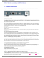
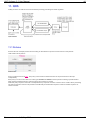
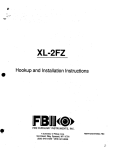
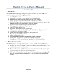
Back panel of UHP has connectors for attachment of radio equipment cables, power and USB. It also has reset button.
UHP back view
Power connector (DC IN)
UHP-1000 router is powered with 24 VDC. AC Power supply adaptor is supplied with the set. The router can be powered
from a DC power source (batteries, DC-DC converter), but the specific power supply mode should be agreed upon with
the Manufacturer. Power supply connector features dimensions 5.5 / 2.1 mm (outer and inner diameters). Positive terminal
of the source is on the center contact.
LAN interface connector
LAN connector is purposed for connecting to Ethernet switch using a straight cable. Bit rate 10 or 100 and duplex mode
are software selectable. Indicators built into the connector mean the following: left one (green) - connection (Link) and data
transmission (Activity), the right one - yellow) - activation of half-duplex mode.
USB Console
The console port provides local control of the device.
RESET button
Router reset is provided using this button. Also, using special combination of pressings this button allows router reset to
factory settings.
High-speed demodulator IF input (SCPC RX)
SCPC-RX is one of the two signal inputs to receive signals from the satellite (LNB). This input is designed to receive
continuous (SCPC/MCPC) carriers in DVB-S and DVB-S2 formats from the satellite. 18 V DC LNB power can be output
to this connector by UHP. Whether power source in on or off, the input can withstand external voltage up to 50 V (power
supply circuit is provided with a diode). Power supply circuit is protected with a self-recovering thermal fuse operating in
case of short circuiting. After short circuiting is removed it may be required to disconnect load from Rx inputs for several
seconds so as to allow the fuse to return to its initial state.
Cable length and cable quality (losses level) can affect the quality and possibility of receiving signals.
Demodulator of the continuous signals is intended for reception of satellite channels transmitted by another UHP router
only. On the physical level, transmission format complies with DVB-S and DVB-S2 standards but the channel information
filling (encalsulation) is proprietary and incompatible with DVB - there are no PIDs, etc.
To receive signal (carrier) from satellite, it is essential to know at least four parameters:
- The satellite used in the network (antenna should be pointed to this satellite)
- Polarization (proper polarization should be selected on in the demodulator configuration or the receive converter on the
antenna should be turned to the required position if its polarization cannot be switched over using its supply voltage)
- Carrier center frequency (enter its value in the demodulator configuration)
- Carrier symbol rate (enter the value in the demodulator configuration)
Channel frequency conversion
Satellite channel frequencies fall into five bands:
- Ka (24.0 GHz - 31.5 GHz) - frequency at which Ka satellites transmit and receive carriers
- Ku (10.7 GHz - 12.5 GHz) - frequency at which Ku satellites transmit and receive carriers
- X (7.2 GHz - 11 GHz) - frequency at which X satellites transmit and receive carriers
- C (4 GHz - 5 GHz) - frequency at which C satellites transmit and receive carriers
- L (950 MHz -2050 MHz) - frequency converted by the receive converter (LNB) and which is applied to the router's
demodulator input
UHP itself outputs and inputs L-band frequencies. RF equipment attached to antenna - BUC transmitter and LNB receiver
shift frequencies to fit them to ranges accepted by satellite.
Document version 1.0, May 2013
7
UHP Software 3.0 User Manual
8
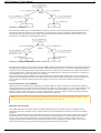
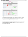
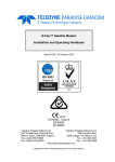
Frequency conversion
Some BUCs and LNBs (most of C-band LNBs) use special conversion scheme having down-side frequency conversion
with spectrum inversion. Inversion occurs when BUC LO is higher than required TX frequency. TDM demodulator can
automatically detect spectrum inversion. TDMA demodulator cannot detect it itself and will not work if inversion is not
switched on on modulator to compensate BUC inversion.
Frequency conversion with BUC spectrum inversion
Reception of the signal is done by receive converter (LNB). It performs two functions: amplification of the weak signals and
converting them to signals at a much lower frequency called intermediate frequency or IF. When converting the frequency,
frequency of the local oscillator (LO) is subtracted from that of the signal received by LNB from the satellite. LO frequency
of various LNBs can be 10 GHz (professional converters), 0.975 GHz and 10.7 GHz (sat TV converters). LO frequency is
usually written on the converter case label or in its Manual.
There are double-frequency (wideband) converters containing two LOs with different frequencies. These converters are
switched over using frequency 22 KHz. UHP-1000 routers do not support 22 KHz control signals and cannot switch LO in
such converters. If converter switches the LO using voltage of 13/18 V, the router will be capable of switching LO
frequency.
Burst demodulator IF input (TDMA RX)
TDMA-RX is the second input for the signal from the satellite (LNB). This input is designed to receive bursts (TDMA) in
UHP proprietary format. The input can also provide, from the router side, supply voltage 13 or 18 V, similar voltages being
simultaneously fed to both inputs. The router can feed this input with a reference signal for using PLL LNB requiring
external reference signal. When reference signal is switched off the router will not distort reference signal arriving at the
input from outside. The rest conditions are similar to those across SCPC RX.
Warning: The total current consumed by external equipment through both RX inputs should not be in excess of 750
mA. Normally, current consumption by DRO LNB is 150 mA, PLL LNB - 500 mA.
Modulator output (TX OUT)
UHP-1000 modulator is compatible with most satellite transmitters/converters (BUC). Those incompatible are only
transmitters that require to explicit "TX On" FSK command but such transmitters are extremely rare and are not widely
employed.
Modulator is connected directly to the transmitter IF connector. Router provides 24 VDC power supply to the transmitter
and 10 MHz reference signal. UHP-1000 is not provided with a separate protection on the transmitter power supply
circuitry. Use is made of current protection for the power supply adapter. In case of a short circuit the router is deenergized and then gets restarted. If power supply is switched on in the configuration, restarts continue at 5 seconds
interval until short circuiting is removed. Powering UHP via TX cable with 24V is possible.
Document version 1.0, May 2013
8
UHP Software 3.0 User Manual
9
Warning: Any operations with TX IF cable should be performed with 24 V supply voltage turned off. Otherwise, selfinduction across a long cable can damage the transmitter and/or UHP. TX out output can feature 24 VDC with a high
short-circuit current. Short circuiting can cause sparks and burns. This voltage can damage measurement equipment
if it is not protected at its inputs. External voltage supplied to this connector will be "diode added" to UHP power
voltage. Supplying negative voltage to center pin more than 24 V of positive voltage is prohibited.
Document version 1.0, May 2013
9
UHP Software 3.0 User Manual
10
3. State analysis
There are several sources giving information about UHP status and problems.
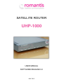
3.1 Front panel indication
UHP has six LED (Light Emitting Diode) indicators on the front panel. These indicators show status information and
information flow through interfaces.
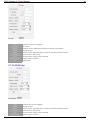
ERROR
"ERROR" red indicator makes it possible to infer about problems in the router functioning. The type of the generated
problem can be judged by the number of indicator flashes:
1 - Demodulator cannot receive MCPC channel from the Hub or other UHP. Please check AGC value in the demodulator
statistics to determine whether there is a signal from antenna (see description of reception problems) to separate LNB
and cable faults.
2 - Router cannot receive TDMA configuration from the HUB (TDM/TDMA network mode). The reason can be in the nonavailability of receive channel from the HUB, CRC errors during reception, wrong configuration of the station.
3 - Router cannot calculate time shift with respect to the HUB. The reason can be in the non-availability of reception or a
large number of CRC errors during reception.
4 - HUB cannot receive signal from this station. Please check transmit signal level of the terminal, whether power supply
and the reference signal for the transmitter are switched on (or off if required), whether DTTS or geographical coordinates
are set correctly in the TDMA settings.
5 - Unit is in Backup state of Redundancy mode. Not an error.
Continuous signal with short dims means that the router has hardware or configuration errors, which can be viewed with
the command # show errors .
If ERROR indicator is continuously lit upon power on it means hardware failure of UHP occured which prevents software
from starting. Try to power it off and power on again or press RESET button on rear panel.
STATUS
"STATUS" green indicator indicates the router operation mode. This indicator is always flashing. If it does not flash it
means that the router is not running properly (try to power off or reset). Slow flashing (once every second) means router
normal operation. Faster flashing (3 times every second) means that a Telnet remote control session is established (in this
case USB console does not operate until session is over).
Fast (6 times every second), simultaneous flashing of "ERROR" and "STATUS" indicators means that the router is
functioning with the factory default configuration. Access to the router in this mode is possible either via USB of via IPaddress 192.168.222.222 (mask 255.255.255.248 or /29).
LOCK
"LOCK" green indicator indicates whether the router receives a channel from the HUB. If there are CRC errors during
reception of information from the channel (e.g. with weak signal from the antenna), the indicator extinguishes for a fraction
of a second at every error. If there are too many errors the indicator may not glow at all in spite of the fact that the router
receives the channel (in this case please check the router demodulator statistics).
TDMA
"TDMA" yellow indicator flashes every time a data placket is received via TDMA RX interface.
SCPC
"SCPC" yellow indicator flashes every time a data placket is received via SCPC RX interface.
TX
"TX" yellow indicator flashes every time a data placket is transmitted in the MCPC mode, and also a burst in the TDMA
mode (bursts can be transmitted even if no data is transmitted inside them).
3.2 Faults
In the router software, there is an information block, which indicates any configuration errors. SYS event in HTTP interface
and "ERROR!!!" message in console prompt appears if the router has any configuration errors:
There are three types of messages:
- Hardware errors.
- Errors associated with the wrong choice of software or router mode.
- Configuration errors.
Current errors can be displayed by clicking on link inside SYS event in using UHP telnet command # show errors .
Document version 1.0, May 2013
10
UHP Software 3.0 User Manual
11
Hardware errors inform about hardware problems with the router. Probably repair is needed.
RAM fail
Errors with router memory.
LAN fail
Errors with Ethernet interface.
FPGA fail
Errors in the programmable logic of router.
Demodulator fail
Errors with SCPC Rx interface.
Burst demod. fail Errors with TDMA Rx interface.
Software or Mode of Operation errors indicate any mismatch between hardware, software and activated feature licenses.
Unit mode not
This mode is not supported by active software. Change software type.
supported
by SW
SW
option missing
Activated mode required special SW feature license. Request option key from manufacturer.
Configuration error messages focus user's attention on the most important points in the router configuration, that may lead
to instability of operation.
DVB-S2 RX not
DVB-S2 RX not supported. Change software type.
supported
FEC cannot
be used FEC cannot be used. Select another modulator FEC (MODCOD).
Long frames cannot Long frames cannot be used. Switch to short frames or change software type.
be used
DVB-S2
16APSK
The maximum symbol rate limit exceeded for DVB-S2 16APSK. Reduce SR.
BurstSR>28000
duration too Too low duration of TDMA time slots (less than 0.3 msec.). Increase slot length.
Framesmall
duration
TDMA frame duration is outside the operating range: from 0.05 to 2 sec. Increase frame length.
invalid
Idle
/ down
Too low values for the status of IDLE/DOWN. Increase value(s).
counters too low
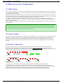
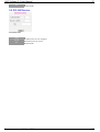
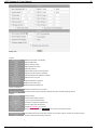
3.3 Events
Events indicate critical conditions of UHP operation. Inducators are red if events are occurring now or yellow if events
occurred before but now their state recovered. Icons remain yellow intil they are cleared with "Clear" link or until UHP is
rebooted. Fault state of stations is transmitted to the hub and then to NMS (if any).
Events
REBT
SYST
LAN
CRC
OFFS
TLC
UHP was rebooted. Self cleard after 30 seconds of operation.
System fault. See fault messages by clicking on link.
LAN interface is down.
CRC errors are occurring on TDM or TDMA RX interface.
TDM RX frequency offset has reached 3/4 of search bandwidth . Carrier search can fail.
TX level driven by TLC has reached maximal allowed value.
Service monitoring generated events.
NWRN
Network side warning (high delay, improper speed).
LWRN
Local side warning.
LFLT
Local (station) side fault. No PING to specified host towards LAN.
NFLT
Network (hub) side fault. No PING to specified host towards hub.
Document version 1.0, May 2013
11
UHP Software 3.0 User Manual
12
4. UHP access for configuration
4.1 USB interface
When router is connected to a computer via a USB cable the computer creates a serial COM port. The port number can
be found in the Device Manager. To access the port use can be made of either the OS-integrated terminal (Hyperterminal)
or third-party terminal programs.
With the fist connection of UHP-1000 Router to PC the system will request the device driver. UHP.INF driver is available
on CD with documentation or can be downloaded from our web site. In response to the request for driver you should refuse
from search in Internet and select setting from the specified place where UHP.INF is saved.
The system will request confirmation for using a non-certified driver. Ignore any system warnings and proceed with
installation. When finished, please check whether a COM port appeared in the Device Manager. If it is appeared you can
start working with the router.
When working with the port from the terminal program the data rate and control parameters can be set to any value since
they are ignored.
Note: With Windows usb protocol stack there is a peculiarity which leads to "hanging" of the usb-port if it carried an
active session and the connected device (router) at this moment was rebooted. in this case you have to log out from
the terminal program and log in again. you can avoid this by cutting off the session by "hang-up" command and only
then restart the router using reset button or via power supply circuit.
4.2 Telnet interface
Remote access to the configuration can be performed using Telnet protocol. The connection can be provided to any of IP
addresses that are set on the router. UHP-1000 supports simultaneously only one Telnet session. In order the hang
session does not block access to the device forever in case on non-activity (pressing ENTER key), the router autoterminates the session after a certain time of inactivity. The time can be set in the configuration, and by default it is 10
minutes.
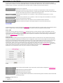
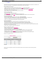
4.3 Default configuration
By default, UHP-1000 router is configured with IP-address 192.168.222.222 with mask 255.255.255.248 (/29).
Respectively, the computer should be configured with an address, e.g. 192.168.222.217 with the same mask.
Reset to default configuration can be made iither with command # config load default or with special reset button press
sequence. Reset button should be pressed 4 times with ~2 second intervals.
Reset to defaults
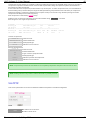
Successful reset will be evidenced by fast and simultaneously flashing indicators ERROR and STATUS.
The default address is not shown in the route Table. And what is more, it disappears after the first saving of the
configuration. Thus the first thing to do, with the Telnet access, is to set a new IP-address (it may be equal to the default
address if needed), exit the session, and connect to the new address and only then save the configuration.
After the first saving of the configuration the ERROR and STATUS indicators stop flashing simultaneously.
Document version 1.0, May 2013
12
UHP Software 3.0 User Manual
13
5. Command interface
UHP has command interface suitable for initial routing setup, monitoring and diagnostics. Command interface works
equally when connecting via USB or Telnet or via local serial console (available in OEM versions of UHP).
Telnet has precedence over USB and serial console. USB has precedence over serial console.
When opening a command session (Telnet of USB) the router can, depending on the configuration, request a password. If
password is not set the commands can be entered immediately.
The system invitation starts with the router name (it is set using the relative command). Then enter "#" symbol in the
administrator mode or ">" symbol in the user mode (user cannot change configuration).
Router commands include key words and parameters. All key words can be reduced to two letters. Letter case is
unimportant. Wrong entered symbols can be edited by returning to them using Backspace key. "Left" and "right" arrows
cannot be used for editing. "Up" arrow is used to recall commands used earlier.
Command syntax meaning
[ ] - optional parameter
x|y - selection of one of the key words, e.g. "on" or "off"
x-y - numerical value in the range from x to y inclusive
STRING - symbols string
IP_ADDR - IP address, e.g. 192.168.0.1
IP_MASK - IP mask in classical or CIDR form (255.255.255.0 /24 /32)
Note: IP address and mask must be separated by blank space - these are different parameters.
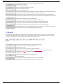
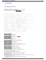
Full list of commands
Commands list can be displayed using # help . Most of commands have equal items in HTTP interface. Commands
which do the things unavailable in HTTP or have additional modes are shown in bold.
UHP# help
---------- IP set-up
address IP_ADDR [1-4095]
- Add IP address to interface [VLAN]
route IP_ADDR IP_MASK IP_ADDR [1-4095]
- Add static route [VLAN]
delete IP_ADDR IP_MASK [1-4095]
- Delete IP address, route or map [VLAN]
update off|on
- Routing table update prevention
---------- System statistics
show profiles
- Show profile settings
show interface ethernet|serial|demod|modulator
- Interface stats
show system
- Show system parameters
show errors
- Show device errors
show memory ram|flash
- Show memory state
clear counters all|ethernet|demod|modulator|tdma|ip|redtl|prot
- Reset stats
---------- Protocol statistics
show ip [0-4095]
- Routing table and forwarding statistics
show arp
- ARP table
show rtp
- RTP header compression statistics
show snmp
- Display SNMP parameters
show dhcp
- Display DHCP parameters
show multicast
- Display multicast parameters
show acceleration
- TCP acceleration stats
show shaper
- Print Traffic Shaper statistics
---------- Satellite network statistics
show net
- Display network state
show stations traffic [1-2040]
- Display stations traffic statistics
show stations [1-2040]
- Show station statistics
show mf
- Show MF inroutes statistics
show tlc
- Show SCPC TLC statistics
show backup
- Show redundancy backup statistics
---------- Demodulator utilities
demod phase-graph
- Display phase constellation
demod bert qpsk|re|data
- Bit error rate meter
demod antenna [0-800] [0-800]
- Antenna pointing mode [RF min] [RF max]
---------- Overall control
admin
- Switch to Administrator mode
exit
- Log out from console
clear interface ethernet|demod|mod|tdma
- Reinitialize interface
ip
ip
ip
ip
Document version 1.0, May 2013
13
UHP Software 3.0 User Manual
14
clear interface ethernet|demod|mod|tdma
- Reinitialize interface
clear arp-table
- Purge contents of ARP table
time set 0-24 0-60 1-31 1-12 0-99
- Set date/time HH MM DD MM YY
unit key 0-15 [0-65535] [0-65535] [0-65535]
- Set features key
watchdog reset|interrupt
- Watchdog timer overflow action
reboot stop
- Stop delayed reboot
reboot [0-1000]
- Reboot device [delay in minutes]
run profile 1-8
- Run profile
network command 0-111111111 STRING
- Command to terminal(s) by SN
---------- Logging & debug management
show log
- Display logs
clear log
- Purge logs
logging interface|demod|config|system|tdma off|on
- Logging events
debug packets|arp|rtp|ping|igmp|dhcp|backup|otg|rip|tlc|smon off|on
- Debugging
---------- Diagnostics
ping IP_ADDR [1-1000000] [40-1500] [1-10000] [0-4095]
- IP Num Len Int/ms VLAN
traffic-generator off
- Disable traffic generator
traffic-generator IP_ADDR 1-50000 36-1470 [0-4095]
- IP Pps Len [VLAN]
---------- Controlled SCPC entry
dama 1-1000000 950000-1800000 100-32000 1-360 1-4 1-28 0-1 :SN FR SR LV MD MC MM
---------- Configuration and SW image management
tftp-server IP_ADDR 0-4095
- TFTP server access
configuration load default
- Load default configuration
configuration load tftp STRING
- Load configuration from TFTP
configuration save tftp STRING
- Save current configuration to TFTP
configuration load 0-1
- Load configuration from specified profile
configuration save 0-1
- Save current configuration to specified profile
image load tftp STRING
- Load image by TFTP to RAM
image load xmodem
- Load image with X-modem to RAM buffer
image load flash
- Copy image from flash to RAM
image write
- Write image from RAM to Flash
erase flash
- Erase flash bank
---------- Boot control
show boot
- Show software boot options
boot main 0-3 0-1
- Main boot profile FLASH_BANK(0-auto) CONF_BANK
boot temp 0-3 0-1
- Temp boot profile FLASH_BANK(0-none) CONF_BANK
boot fallback timeout 1-10000
- Temp image auto fallback period (min)
boot fallback stop
- Abandon auto fallback
---------- Help
help
- Print this help
Document version 1.0, May 2013
14
UHP Software 3.0 User Manual
15
6. HTTP interface
6.1 Introduction
UHP has plenty of control and statistics parameters which will be described further. Some parameters can have many
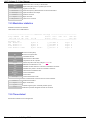
discrete values which will also be explained. To classify different parameters special style conventions were implemented:
Style conventions
WWW field
Output value
Parameter value
Input field of WWW interface form changeable by user.
Statistics value displayed in WWW or Telnet statistics page.
Set of values of certail parameter.
# Telnet command Command of Telnet interface.
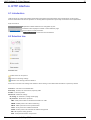
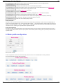
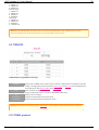
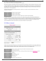
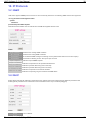
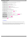
6.2 Selection tree
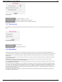
Selection tree
- folder which can be opened
- control icon showing settings
- statistics icon showing real time statistics
Some items can have both settings and statistics. When clicking on item titlecontrol information is opened by default.
Overview - overview of overall UHP state
Site setup - location, RF connections, frequency shifts
Profiles - 8 service profiles
Advanced - advanced settings
IP routing - IP addresses, routing and bridging
IP protocols - All IP service protocols
ARP - ARP protocol MAC to IP address translation on LAN
SNMP - SNMP protocol for external monitoring
SNTP - SNTP protocol for time synchronization
TFTP - TFTP protocol for software download
DHCP - DHCP protocol for automatic IP address assignment
RIP - RIP dynamic routing protocol
RTP - RTP packets headers compression
Document version 1.0, May 2013
15
UHP Software 3.0 User Manual
16
Multicast - IGMP protocol for videoconferencing
Acceleration - TCP acceleration
COTM/AMIP - Interface to mobile antennas
Other - Other IP related settings
QOS - Quality of service settings
Policies - Filtration, prioritization rules for IP packets
Shapers - Rate limiting, guaranteed speeds
Realtime BW allocation - TDMA bandwidth requesting for rea ltime traffic
Service mon - Quality of service monitoring
Network - Network related settings and stats
Overview - TDMA protocol stats
Stations - Stations setup and stats
MF-TDMA - Multi frequency TDMA stats
ACM - Automatic coding and modulation stats
System - System parameters
Overview - General system stats
Ethernet - LAN mode and stats
Demodulator - High speed demodulator stats and pointing option
Modulator - Modulator stats
Time related - Time zone, console timeout
User access - Passwords
Flash/Boot - Software boot control
Save/Load - Configuration saving and loading
Maintenance - Maintenance utilities
Support info - Information printout for technical support query
Pointing - Antenna pointing screen
Network command - Issuing commands on stations from hub
Traffic generator - Configurable generator of IP packets
Save config - Saving current configuration to flash memory
Telnet session - Launch telnet session to UHP
>
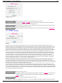
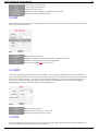
6.3 Statistics frame
Statistics frame displays realtime information about UHP state. It is automatically refreshed every 5 seconds. In case of
loosing a link to UHP browser can display error instead of information here. In this case user should refresh the page with
browser "Refresh" button of F5 key. Some items of top frame are links to appropriate settings or stats.
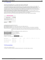
Top statistics frame
Name
Uptime
Profile
State
Events
Clear
Interfaces
Name set in site setup
Uptime since reboot in timestamp format
Currently running profile , format is number-type (title)
Current profile state
Current status of events (red-current, yellow - historic)
Clear historic events
State of interfaces (green means interface is up)
Then events are listed. See state analysis chapter.
Document version 1.0, May 2013
16
UHP Software 3.0 User Manual
17
6.4 Main screen overview
Overview screen shows thorough real time statistics of software modules. It is automatically refreshed every 30 seconds.
In case of loosing a link to UHP browser can display error instead of information here. In this case user should refresh the
page with browser "Refresh" button of F5 key. Some items of overview are links to appropriate settings or stats.
Screen consists of several sections. First three sections are always there, other section presence depends on current
profile mode and activation of certain services. All information from sections is also available in extended statistics
screens which can be opened from tree or from direct links in sections.
UHP overall information section
Overview section
Refresh
SN
SW
Ver
CPU load
Buffers
Temp
Profile
Link for immediate refresh of the frame.
UHP serial number.
Currently running software type. Link to select software bank.
Currently running software version and its release date.
Load of CPU in percent, loads above 60% are not recommended.
Percentage of IP packet buffers free.
Internal temperature, range 0 to 60 is acceptable.
Duration of current profile state and number of runs so far.
Interface statistics section
Interface statistics
Main operation information, traffic and errors for each interface are shown. Counters can be cleared in clear counters
screen. For LAN interface link state is shown, for demodulator search information or reception quality, for modulator TX
level and TLC state. For Network interface number of RX errors is a sum of all errors of all stations plus errors of TDMA
protocol itself.
Network statistics section
This section appears only if current profile is hub profile. Section is divided into three colums showing statistics of stations,
bandwidth allocation and TDMA protocol.
Network statistics
Stations
Enabled
Online
Number of enabled stations in stations table
Number of online stations.
Document version 1.0, May 2013
17
UHP Software 3.0 User Manual
Active
Hub C/N low/high
Rem C/N low/high
18
Number of active station s which are requesting bandwidth.
Number of stations having 1 dB lower/higher C/N on hub than set hub TLC reference.
Number of stations having 1 dB lower/higher C/N on station than set remote TLC reference.
Bandwidth
Total Req
RT Req
CIR Req
Request slots
Load
Amount of time slot requested by all stations (equivivalent traffic in kbps).
Amount of time slots requested by all stations for realtime traffic.
Amount of time slots requested within shaper guaranteed speeds CIR.
Amount of time slots allocated in frame for station bandwidth request
Persentage of requests related to frame length can be >100% during overload.
TDMA
BD RF lvl
FP lost
TTS
TTS errors
Act channels
Total input RF level on burst demodulator input.
Number of frame plan lost so far, increasing means packet drops.
Measured or set TTS .
Number of TTS measurement errors so far.
For MF-TDMA number of active return channels.
Station section
Station section
Number
FP lost
DTTS cor
Frq cor
Lvl cor
Number of station in the network.
Number of frame plan lost so far, increasing means packet drops.
Corrected value of DTTS after acquisition.
TX frequency correction after acquisition.
TX level correction according to hub TLC settings.
Bandwidth
Cur Bw
Sum Req
RT Req
Codecs
Timeout
Amount of time slot allocated now to this station (equivivalent traffic in kbps).
Amount of time slots requested by station.
Amount of time slots requested by station for realtime traffic.
Amount of realtime codecs assumed.
Timeout counter of realtime bw requesting algorithm.
Traffic generator section
Traffic generator section
This section appears only if traffic generator is activated. Generator settings are shown.
Redundancy section
Redundancy section
This section appears only if redundancy is activated. Redundancy state is shown.
TLC section
TLC section
This section appears only if TLC is activated. TLC state and settings are shown.
NMS section
Document version 1.0, May 2013
18
UHP Software 3.0 User Manual
19
NMS section
This section appears only if NMS access is activated. Current NMS IP address is shown.
Document version 1.0, May 2013
19
UHP Software 3.0 User Manual
20
7. Site setup
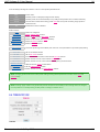
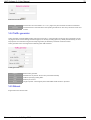
Site setup
Site setup screen allows to configure UHP parameters related to installation site.
First unit name is configured. This name appears in top frame and in Telnet command prompt.
Location
Site georgaphical location is specified. Location is used in TDMA timing calculations for stations and neseserity of
location setup depends on timing mode selected. By default location is required for proper TDMA station installation.
RF interface
Here parameters needed for proper functioning of antenna RF equipment are set. Compensations for RF equipment or
satellite frequency shifts are also set here. Compensations of frequencies are needed to adjust actual RX and TX
frequency values to adjust values supplied by hub.
Receive LO
Local oscillator of LNB. Obtained from datasheet. Typical values are 10000000 or 9750000 kHz.
This value is usuallly subtracted (if spectral iversion is off) from all RX frequencies set in profiles
or received from hub within return channel configuration to produce final L-band вњ– value of RX
frequency set on demodulator 950000-2150000. If value is zero (by default) all frequencies should
be set in L-band.
Critical: LO frequencies should either be properly set on WHOLE network or left zeroes on
WHOLE network. Mismatch can result in completely wrong final frequency calculations,
system faults, no service, carrier interference.
Transmit LO
Power
Local oscillator of BUC transmitter obtained from datasheet. Typical values 13050000 or
12800000 kHz. This value is subtracted from all TX frequencies set in profiles or received from
hub within return channel configuration to produce final L-band вњ– value of TX frequency set on
modulator 950000-1750000. If value is zero (by default) all frequencies should be set in L-band.
The same warning as in receive LO applies.
Turns on LNB power 18V on demodulator or 24V power for BUC on modulator, see current
limitations in specification.
10MHz
Document version 1.0, May 2013
20
UHP Software 3.0 User Manual
10MHz
SpInv
Frequency adjust
Carrier search bw
Identification
21
Turns on 10 MHz signal on burst demodulator connector or modulator connector.
Spectrum inversion Setup on RX or TX. Wrong setting will terminate the service.
Signed adjustment figures for two demodulators and modulator.
Range around set frequency (+/-) where carrier search is done by demodulators. Widening range
slows search, narrowing can result in faiiling to find the carrier.
Net ID and RF ID are set here allowing to dedicate UHPs to networks or satellites.
Warning: Applying settings in this form (even without changing) results in current profile restart.
Warning: When use is made of splitters and combiners for connection with radio equipment, it is essential that
enough 10 MHz reference signal level on LNB and BUC be maintained. Conventional low cost and simplified dividers
and adders introduce 5 to 10 dB attenuation. This attenuation usually does not create problems for RF signal, but
10M reference signal level may become insufficient, and this will lead to non-availability or instability of reception. It
makes sense to use professional dividers to ensure reference signal passage without losses via one of the ports.
Document version 1.0, May 2013
21
UHP Software 3.0 User Manual
22
8. Profiles
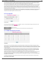
8.1 Profiles basics
Profile is a set of settings needed to set up station or network service. UHP configuration includes 8 profiles. All of them
are independent of one another. Each profile can be configured in any profile mode with appropriate set of settings.
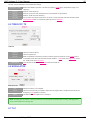
Profile list
Num
Mode
Valid
Autostart
Check
Title
Run
Runs
Profile number
Mode of operation, also a link to open profile settings
Whether profile is marked valid (configured)
Whether profile can be automatically run by UHP (several profiles can be marked auto-startable)
Not used now
User set title
Link for manually running profile
Number of profile runs so far
There is a corresponding Telnet interface command # show profiles which shows similar table
plus information about currently running profile.
8.2 Profile running rules and profile operation states
Only valid profiles can be potentially run - protection from running partially configured or unwanted profiles. Only profiles
with autostart will run on themselves upon UHP power on. Profiles without autostart set can be run only manually.
Warning: Do not forget to make desired profile valid and autostart or it will not be rerun upon fail.
Running profile means switching software operation to mode set in profile, setting RF parameters and making all the rest
to fully support selected profile mode. Only one profile runs at any given time. Profile can run through different states until it
reaches last state "operation". There are 17 states which are switched sequentially however some states are omitted in
certain profile modes ( for example all TDMA states in SCPC modes).
OFF
Init
No config
Use config
Redundancy
Start RX
COTM stop
profile is inactive
Initialization of UHP subsystems.
(hubs) NMS mode selected but no configuration received from NMS.
Application of configuration.
Checking for redundancy state, waiting in redundant mode while other set operates.
Turning on reception.
Document version 1.0, May 2013
22
UHP Software 3.0 User Manual
COTM stop
Start hub TX
Waiting for RX
Identify
Get net config
Measure delays
Start TDMA
Start TX
Acquisition
Adjustment
Waiting stations
Operation
23
Waiting if mobile antenna has disabled transmission or did not supply location.
Turning on transmission on hub.
Waiting for demodulator to lock in modes requiring reception.
Determining station number and inroute from hub control information set in hub stations table .
Waiting for return channel configuration from hub.
Calculating TDMA timing information.
Starting TDMA operation.
Waiting if transmission is disabled by configuration or COTM antenna controller.
Starting to transmit special qcquisition bursts to hub.
Hub has seen transmission from station and is adjusting station frequency and timing.
For hub modes waiting for at least one station to come up.
Final state. Successful profile operation.
Profile execution
If profile reaches operation state profile succeeds and continues running indefinitely or until some events depending on
mode occur requirinn profile to fail - carrier down, all stations down, ... Some states require certain conditions to proceed
further to next state (example - SCPC or TDMA reception in "Waiting for RX" state. If at some intermediate state required
conditions are not met during user specified timeout profile also fails.
Profile auto-switching
If profile fails UHP looks sequentially through all subsequent profiles. If it finds another profile with autostart this profile is
run. After ending with profile 8 system loops to profile 1 and continues profile scanning until any autostart profile reaches
operation state.
8.3 Basic profile configuration
Basic profile settings
Profile configuration consists of several tabs with parameter sets. List of available tabs is under profile title.
Set of tabs depends of profile mode. Examples:
Document version 1.0, May 2013
23
UHP Software 3.0 User Manual
24
First and always existing tab is "Basic". This is a main profile parameters tab.
Mode
Valid
Autostart
Timeout
Title
Profile mode.
Whether profile is valid (fully configured and usable).
Whether profile can be automatically run by UHP (several profiles can be marked autostart).
Timeout value counted down during profile state wait. If any state is waiting longer profile is
assumed to fail.
Profile title to show in statistics.
Station modes
none
SCPC Modem
Star Station
Mesh Station
Hubless Station
DAMA Station
profile not configured
SCPC / MCPC TDM modem
Station of star (including MF-TDMA )network
Station of star network with mesh capability
Station of hubless network
Station of DAMA network
Test mode
Pure Carrier
Test mode producing unmodulated pure carrier for cross polarization or spectrum purity testing
Hub modes
Star Hub
MF Hub
Outroute
Inroute
MF Inroute
Hubless Master
DAMA Hub
DAMA Inroute
Hub of star TDMA network
Hub of MF-TDMA network
Forward channel transmitter of star network outroute channel
Return channel receiver of star network inroute channel
Return channel receiver of star network multifrequency inroute channel
Hubless network master control station
Hub for DAMA MCPC network
Return channel receiver for DAMA MCPC network
Note: Changing profile mode clears entire profile settings loading default parameters and also clears valid and
autostart flags.
Note: Pressing "apply" button in any profile tab (several exceptions noted further) even if settings were not changed
re-runs profile if it is currently running. If other profile is running it continues to run.
8.4 TDM/SCPC RX
TDM RX
Document version 1.0, May 2013
24
UHP Software 3.0 User Manual
25
This tab controls TDM/SCPC demodulator RF settings.
Demodulator enable
Frequency
SymRate
Standard
Check RX
Enable demodulator operation. This field is omitted in mode where demodulator usage is not
obligatory.
Receive center frequency.
Receive symbol rate. See limitations for S1/S2 standards in specification.
DVB-S1 / DVB-S2 mode switching.
Forces check of reception presence. If no carrier is received profile execution will wait in state
Waiting stations If RX is not checked profile will pass to operation .
8.5 TDM/SCPC TX
TDM TX
Frequency
SymRate
S2-mode
FEC/MODCOD
Transmit center frequency.
Transmit symbol rate.
Data encapsulation and framing mode for DVB-S2. Ignored in DVB-S1 mode. CCM mode is
compatibility mode with older non-ACM boards. ACM-LF - ACM mode with long frames ,ACMSF - ACM mode with short frames
FEC selection for DVB-S1, MODCOD selection for DVB-S2.
8.6 MODULATOR
MODULATOR
TxOn
TX level
Adjust
Allows transmission on modulator.
Transmit level (set level) of modulator. Expressed in negative dBm. Actual transmit level can be
changed by TLC algorithm if enabled.
Two buttons allow to adjust level in 1 db steps.
Note: Changing level by buttons or altering value does not restart profile if edited profile is running. Changing TxOn
value restarts profile if it is running now.
8.7 TLC
Document version 1.0, May 2013
25
UHP Software 3.0 User Manual
26
TLC
TLC - transmission level control allows to adjust local transmission level based on information about reception quality on
remote side. Goal of TLC algoritm is to provide desired "reference level" (C/N on remote side. Reference must be
selected to allow error free reception. Reference should be at least 0.5 dB higher than threshold C/N. Upper value is not
explicitly limited. Generally TLC algorithm is supplied with deviation between reference and actual reception levels on
remote side(s) and adjusts local TX level to reduce this deviation to zero. Source of deviation value depends on operation
mode
SCPC TLC
In point to point (SCPC) modes reference level is specified on remote side. Deviation is calculated as actual deviation on
remote side and transmitted to local modem via IP protocol. Operation of TLC can be unidirectional or bidirectional. TLC
shares protocol with NMS so both parties should have configured passwords and other data required for information
exchange.
Hub TLC in network modes
In network modes (star, hubless, DAMA) desired levels of both local (hub) and remote (stations) sides are specified on the
hub. Hub adjusts its TX level based on C/N information supplied by remotes via TDMA service protocols. No need to
configure anything on stations for C/N level transfer to hub - it is accomplished automatically.
Hub also reports deviation between desired reference level on hub and actual reception level of each station to this
station. If TLC is enabled on stations they can use this information to adjust their TX levels.
For regulation of hub TX level, deviation calculation is more complex as it involves averaging of multiple remote C/N
values. Sometimes it can be desirable to preserve some average optimal level on stations, sometimes it is required to
provide even the worst receiving stations with enough C/N. Sometimes it is desirable to regulate TX level based on own
self-reception only. To cover all this cases strategy mechanism is used. Strategies allow to fine tune TLC operation of hub.
TLC strategies
The level of transmission of point-to-point SCPC links can be automatically adjusted to ensure proper reception of the
receiving side of the link. The predefined level set on receiving station is continuously compared with current level and
transmitting site in notified about such difference. Is TLC feature is activated on transmitting site it will try to adjust the level
Document version 1.0, May 2013
26
UHP Software 3.0 User Manual
27
to ensure optimal level of reception on the receiving site. TLC can be activated for both or just one direction of duplex
SCPC link. In contrast to TLC in the TDM/TDMA networks and HUBLESS TDMA, SCPC TLC parameters are transmitted
between stations over UDP, which allows you to send them both via satellite and by terrestrial networks.
TLC enable
Max TLC TX level
Net(0)-Own(16)
strategy
Avg(0)-Min(16) strategy
Desired C/N on local
hub/SCPC
sideon
Desired
C/N on
Enabling of TLC algorithm.
Maximal level allowed to reach during TLC operation. The upper limit for cases when most of
transmitter power is used should be set by 1 decibel above the BUC compression point, whereas
the lower limit should be placed 8-10 decibel below the upper limit.
Which behavior dominates in TLC operation - orient on network reported levels or on own
reception.
Which behavior dominates in TLC operation - orient on average level of all stations or on level of
the worst case level from all stations.
Reference C/N level on hub. Hub wants to receive all stations with this C/N level.
Reference C/N level on stations. Hub wants all stations to receive hub with this level.
TDMA remotes side
8.8 ACM
ACM function allows to change transmission MODCOD on the fly without data loss. Function works only in DVB-S2 modes
SCPC or TDM modes. Two major ACM modes are realized - SCPC point to point ACM and network ACM.
SCPC ACM
In this mode remote C/N level received via TLC exchange protocol is used to optimize coding and modulation of local
transmission to maximize channel bandwidth or provide stable channel operation under fading conditions. Entire channel
starts working with new MODCOD. If there is no remote reception or no data from remote side coding is returned to the
value set in TDM/SCPC TX profile settings.
Network ACM
In this mode forward TDM channel carrying information towards stations is divided into four sub-channels each working
with different MODCOD. MODCODs are fixed and set in configuration. Hub receives current C/N from each station and
based on internal C/N threshold table divides all stations to four groups. Forward traffic for this four groups goes through
appropriate four sub-channels. First sub-channel (1) is base sub-channel where all network service information is
broadcasted. Traffic can also be transmitted via this sub-channel. All stations start working in sub-channel 1 then go to
other sub-channels if their reception is good enough. MODCOD of sub-channel 1 is set in TDM/SCPC TX settings and is
lowest (most robust) amount other sub-channels to ensure all stations will receive hub in fade conditions. Other
MODCODs must sequentially increase for proper operation of ACM algorithm.
ACM
ACM enable
MODCOD2
MODCOD3
MODCOD4
C/N threshold
Enable ACM. DVB-S2 ACM-Long or ACM-short mode should be configured in TDM/SCPC TX
MODCOD of the second sub-channel.
MODCOD of the third sub-channel.
MODCOD of the fourth sub-channel.
Margin over MODCOD C/N thresholds for sub-channel assignment. Should be set at least 0.5 dB
for stable operation.
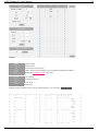
Examples of MODCODs set:
Low range:
1 - QPSK 2/3
Document version 1.0, May 2013
27
UHP Software 3.0 User Manual
28
2 - QPSK 3/4
3 - QPSK 5/6
4 - QPSK 8/9
Medium range:
1 - QPSK 2/3
2 - QPSK 5/6
3 - 8PSK 2/3
4 - 8PSK 8/9
High range:
1 - QPSK 2/3
2 - QPSK 8/9
3 - 8PSK 5/6
4 - 16APSK 3/4
Warning: Using MODCODs with FEC below 2/3 can make ACM algorithm to work unstable because of low
difference between C/N. At This moment FEC 1/2 in any modulation does not work.
8.9 TDMA RF
TDMA RF (last string is cut intentionally)
SymRate
Symbol rate of TDMA carrier. Symbol rate is involved in TDMA protocol calculations and after
setting or changing SR protocol parameters frame length and slot size can need adjustment to
keep optimal (or valid) frame duration and slot duration
FEC
Error correction coding.
Carrier definition (single carrier in HUB mode, up-to 16 carriers in MF-TDMA HUB mode).
On
Enable carrier for usage.
RX frequency
Frequency at which hub receives the carrier.
TX frequency
Frequency at which stations transmit the carrier.
Warning: Remember about RX LO usage in Site setup to avoid unexpected final TX frequencies on stations.
8.10 TDMA protocol
Document version 1.0, May 2013
28
UHP Software 3.0 User Manual
29
TDMA protocol
Inroute number
Frame length
Slot size
Stations
Number of inroute channel. Should be unique for each hub inroute.
Length of TDMA frame in time slot Must be multiple of four. At high symbol rates in MF TDMA
mode automatically rounded down to nearest 8 or 16.
Size of time slot in 32 (for FEC=2/3) or 40 (for FEC=5/6) bytes increments. Lower value is used
at lower symbol rates and vice versa.
Number of stations in the inroute. Should be less or equal to number of stations in stations table
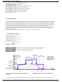
8.11 TDMA Timing
Timing
All stations receive from Hub data test packets used by OC to measure TTS. Using these packets stations perform
partially procedures on synchronizing to Hub. TTS calculation algorithm statistics on station shows TDT (Time Delta). TDT
itself is not informative for the diagnostics, however TDT value preserves its meaning and should be greater than 1, and
otherwise station will not try to communicate with Hub. TDT can be zero if station does not receive Outroute from Hub.
Stations are certain distance away from the satellite (the distance is different for each stations location). Thus each station
has its own TTS. station TTS must be known with a high accuracy, otherwise their TDMA busts will overlap and cause
transmission errors. One stations with wrong information about its TTS can block normal operation of the entire Inroute.
For network station, use is made of the difference between the given station TTS and Hub TTS instead of TTS absolute
value. This difference is referred to as DTTS and also is measured in microseconds DTTS_station = TTS_station TTS_hub. If station is co-located with Hub, then its DTTS is zero. If station is located closer to satellite than Hub, then its
DTTS is negative, and if farther - then it is positive. Usually DTTS lies in the range from -8,000 to 8,000 us in networks
covering a large territory, and from -1,000 to 1,000 in regional networks.
Hub (OC) is capable of receiving its own transmission and hence can measure its own TTS at any time. stations do not
have such capability since their transmission normally can be received only by Hub, hence only Hub can determine
accurately the exact DTTS value for each station. It is worth noting that Hub cannot measure station DTTS in any frequency
band since Inroute channel is used also by other stations, and station with no knowledge of its own DTTS at all cannot fit its
transmission at moments when Hub permits station to transmit.
Thus, with the first connection to the network, DTTS calculated for the station with certain accuracy should be set in the
station. If the accuracy is sufficient Hub will receive special shortened TDMA packets from this station, calculate the timing
error and immediately send the error value to the station via Inroute. station will adjust its DTTS value on the Hub command
and will start normal operation in the network. This corrected DTTS value will be present in the station TDMA statistics and
can be entered in station as the final value.
Timing mode
Satellite longitude
Value
Selection of timing source.
Longitude of satellite orbit point. Should be properly set if stations use location or GPS modes for
timing calculations because longitude is broadcasted to all stations and there participates in
DTTS calculations.
TTS or DTTS value when timing mode set to "value".
The required accuracy in the calculated DTTS value is +/-0.25 of the TDMA burst duration. TDMA burst duration depends
Document version 1.0, May 2013
29
UHP Software 3.0 User Manual
30
on several factors (symbol rate, TDMA burst duration) and is presented in TDMA statistics. Usually, TDMA burst duration
lies in the range from 500 to 10,000 us, and thus calculated DTTS value accuracy lies in the range from 63 to 1,250 us.
This accuracy is sufficient for Hub to capture station without causing interference to other stations.
If accuracy of the calculated value is within +/-0.25 of the TDMA burst duration, then interferences for one or more stations
in the network will be generated at the moment when "inaccurate" station is establishing communication with Hub (for a
few seconds). Then station DTTS will be adjusted by Hub, and station will work without interferences. During installation of
station, it will not be a problem, but what is important is that DTTS value logged into station is afterwards corrected.
If DTTS is corrected on station with an error exceeding 0.5, Hub will not "see" station at all, and this station will, most likely,
create interferences for other stations.
To calculate DTTS value, use should be made of the UHP Installation Calculator utility to calculate the initial DTTS value as
well as elevation and azimuth towards satellite. These parameters can be calculated if Hub and station geographical
coordinates and satellite longitude in the orbit are known.
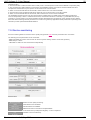
8.12 Crosspol RF
Crosspol RF
Used for producing unmodulated pure carrier on modulator. Used for cross polarization leakage measurement, P1dB
measurements, spectrum purity check and other tests.
Frequency
Duration
Center frequency.
Duration of test. After this period next profile will be automatically picked.
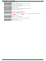
8.13 TDMA Bandwidth allocation
TDMA BW
Stations that are not in the network (switched off temporarily) shall be provided with a possibility of joining the network
when switched on. That is why Hub must provide such stations with some bandwidth. The wider this bandwidth is the faster
stations establish communication with Hub when switched on, and the more bandwidth will be wasted when these stations
remain switched off.
A similar situation exists with stations operating in the network but at the moment not requesting a bandwidth owing to
absence of user traffic. These stations should also be provided a possibility, from time to time, to request a bandwidth
from Hub when needed. The more frequently bandwidth is provided for request to such stations, the faster network will
respond to emergence of traffic but the more bandwidth will be wasted if stations do not make use of it.
TDMA network operation conditions can be substantially different, e.g. access to Internet where traffic changes randomly
and a quick response to its changes are required, or SCADA where multiple stations occasionally transmit short
messages and practically there are no critical requirements to delaying these messages, but it is recommended that the
bandwidth in use be minimized.
To enable the possibility to provide optimal functioning of various-purpose networks, UHP Hub first of all dynamically
divides stations into three groups:
down - stations not in the network.
Document version 1.0, May 2013
30
UHP Software 3.0 User Manual
31
idle - stations in the network but not requesting bandwidth.
active - stations in the network and making requests for bandwidth.
Each group is assigned a probability with which Hub will allocate a bandwidth to stations belonging to this group. The term
"allocate a bandwidth" means providing at least one TDMA time slot. Probability is a number from 1 to 255 meaning how
many times during 255 sequential TDMA frames Hub (IC) will provide each station with one TDMA slot for transmission. If
probability is 255, such slot is provided to stations in each frame. If probability is 128, such slot is provided in each other
frame, and if 32 - in each eighth frame
Table here defines bandwidth requesting parameters of stations. For profiles exist. Each TDMA station is always
assigned one of profiles.
Active
Idle
Down
Timeout
Coefficient for active stations.
Coefficient for idle stations.
Coefficient for down stations.
Timeout in frames to declare station idle if it doesn't request bandwidth.
A question may arise on why probability is needed for active stations if they request a bandwidth and already have a
possibility to transmit new requests to Hub. But if there is a request for bandwidth it does not mean that they will get it - it
depends on the network and traffic settings. But if these stations do not obtain a bandwidth, Hub should be aware of their
requests, e.g. owing to the fact that requests from stations may grow and then Hub will allocate a bandwidth for them.
Typical probabilities are 255 for active stations, 32 for idle ones and 32 for "down" stations.
8.14 Return channel
Return channel
DAMA mode return channel settings for one remote station are set here. Station transmission can be fully controlled. This
interface theoretically allows to control network of stations but as local unit can receive only one station receivers for other
stations should be configured elsewhere. More complex networks can work only under NMS control.
Station number
Serial number
Frequency
SymRate
S2-mode
FEC/MODCOD
TX level
TX mode
Number of station. Station will report its state and stats with this number.
Serial number of station.
Transmit frequency of station. (meaning of further parameters are like TDM/SCPC TX screen
settings)
Symbol rate.
Mode of DVB-S2 coder.
MODCOD or FEC.
Transmit level.
Modulated or pure carrier mode.
Document version 1.0, May 2013
31
UHP Software 3.0 User Manual
32
Document version 1.0, May 2013
32
UHP Software 3.0 User Manual
33
9. Routing and Bridging
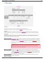
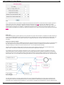
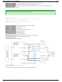
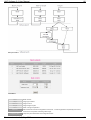
9.1 SVLAN overview
UHP-1000 routers make use of a special protocol to transmit information via the satellite. Requirements to such protocol
are minimal overhead and a possibility to split and group data streams. With the UHP-1000 routers, this protocol is named
SVLAN.
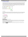
SVLAN channels are similar to the VLAN notion in Ethernet but it is simpler - it is just "pipes" with numbers. If you send
traffic into such a pipe (SVLAN) at the modulator, then at the other link end you will receive these packets to be dealt with
by the IP-router, provided you set the same SVLAN number for reception.
SVLAN with number 0 differs from others by that traffic through it is transmitted without additional headers at all, thus
providing the highest transmission efficiency. The rest SVLAN (1-4000) add two bytes to each packet.
Into one SVLAN one can, using router facilities, route the required number of networks, each of them having its own priority
level.
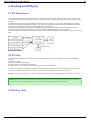
Routing schematics
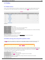
9.2 IP router
UHP-1000 routers implement a standard IP-router supporting static routing. The routing table can contain the following
records:
IP-address on LAN
Statistical route in the LAN direction
IP-map - a route to the modulator into SVLAN
SVLAN Receive - a command to receive SVLAN from one of the demodulators
Records in the Table are arranged according to the network mask. The first ones are records with mask /32. Any of the
records can contain VLAN and then it is referred to the Table of the relevant VLAN and will work only in it.
Altogether, the Table can contain up to 1,000 records. Routing speed is practically independent of the number of records.
Note: UHP-1000 router has no limitations on overlapping the addresses, incompliance of masks, etc. This makes it
possible to obtain more capabilities from routers but these capabilities should be used with care.
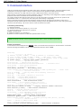
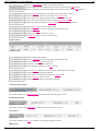
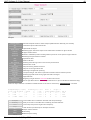
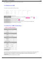
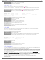
9.3 Routing Table
Document version 1.0, May 2013
33
UHP Software 3.0 User Manual
34
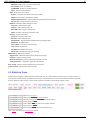
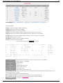
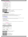
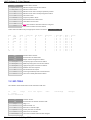
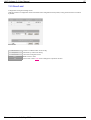
Routing Table
Strings description:
Bridge - VLAN 5 is bridged to satellite SVLAN 67
IP addr - IP address 10.0.0.11/24, untagged
Tagged IP - IP address 10.0.0.11/24 in VLAN 7
TX map 1 - Network 20.0.0.0/24 routed to satellite SVLAN 11, low priority, to station 2
High prio - Network 40.0.0.0/20 routed to satellite SVLAN 33, high priority, to station 888
Pol CIR - Network 60.0.0.0/17 routed to satellite SVLAN 17, policy 76, shaper 15, to station 9
Default - Default gateway to 10.0.0.1
RX SVLAN - SVLAN 22 received to untagged VLAN 0
VL7 RX - SVLAN 44 received to VLAN 7
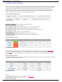
The same table displayed with # show ip command.
T VLAN Network/Source
Mask Destination
M 5
Bridge
LOW->67
A
10.0.0.11
/24
LAN,LOCAL
A 7
10.0.0.11
/24
LAN,LOCAL
M
20.0.0.0
/24 LOW->11
M
40.0.0.0
/20 HIG->33
M
60.0.0.0
/17 POL->17
R
0.0.0.0
/0
10.0.0.1
V
RX SVLAN 22
V 7
RX SVLAN 44
Unrt: 1406
Last: 10.0.0.10 -> 10.0.0.11
PxARP: OFF PolDrops: 0
T
VLAN
Network/Source
Mask
Destination
Stn
Pol
TrSh
Packets
Unrt
Last
IP Scr
Px ARP
Stn
6
Pol
TrSh Packets
0
16926
0
2
0
888
0
9
76
15
0
0
0
0
IP Scr: A/ON (0)
Title
Bridge
IP addr
Tagged IP
TX Map 1
High prio
Pol CIR
Default
RX SVLAN
VL7 RX
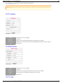
Type of record A - IP address, R - static route, M - IP map, V - SVLAN RX.
VLAN if tagged or - if untagged.
Network address.
IP mask.
Routing or map destination.
Station number for maps.
Policy number if set.
Traffic shaper channel number if set.
Number of packets passed so far. Maximal value is 65535!!! Packets for static routes are not
counted.
Number of unroutable packets.
Source and destination IP addresses of last unroutable packet.
Current mode of IP screening and number of packets screened.
Proxy ARP mode.
PolDrops
Document version 1.0, May 2013
34
UHP Software 3.0 User Manual
PolDrops
35
Number of packets dropped by all policies.
Warning: Maximal value of packets counters on this screen is 65535. Then they continue counting from 0.
9.4 IP address
IP address
VLAN
IP address
Net mask
Local access
Title
VLAN number or 0 for untagged.
IP address.
Network mask in dotted (255.255.255.0) or classless (/24) notation.
Whether UHP control mechanisms (HTTP,SNMP,NMS) will listen on this IP address.
Optional title.
9.5 Static Route
Static Route
VLAN
IP network
Net mask
Gateway
Title
VLAN number or 0 for untagged.
IP network.
Network mask in dotted (255.255.255.0) or classless (/24) notation.
Route destination. Destination reachability is not checked.
Optional title.
9.6 TX map
Document version 1.0, May 2013
35
UHP Software 3.0 User Manual
36
TX map
VLAN
IP network
Net mask
SVLAN
Station
Priority/policy
Policy
Shaper channel
Title
VLAN number or 0 for untagged.
IP network.
Network mask in dotted (255.255.255.0) or classless (/24) notation.
SVLAN number.
Station number. Map traffic will be counted as TX traffic towards this station.
Fixed priority or policy mode.
Policy selection if policy mode is selected.
Shaper channel selection.
Optional title.
9.7 VLAN Bridge
VLAN Brige
VLAN
SVLAN
Station
Priority/policy
Policy
Shaper channel
VLAN number or 0 for untagged.
SVLAN number.
Station number. Map traffic will be counted as TX traffic towards this station.
Fixed priority or policy mode.
Policy selection if policy mode is selected.
Shaper channel selection.
Document version 1.0, May 2013
36
UHP Software 3.0 User Manual
Title
37
Shaper channel selection.
Optional title.
9.8 SVLAN Receive
SVLAN Receive
VLAN
SVLAN
Title
VLAN number or 0 for untagged.
SVLAN number to receive.
Optional title.
Document version 1.0, May 2013
37
UHP Software 3.0 User Manual
38
10. IP Protocols
10.1 SNMP
UHP router supports SNMP protocol versions V1 and Community-based V2. The following SNMP classes are supported:
.iso.org.dod.internet.management.mib2.
system.
interfaces.
private.enterprises.UHP.uhpV30.
Information about variables can be obtained from the MIB file supplied with the router.
SNMP
Read community
Wrt. community
IP permitted 1
IP permitted 2
Input requests
Illegal IP address
Wrong rd.community
Wrong wr.community
No variable in MIB
Table out of index
Password for reading SNMP variables.
Password for writing SNMP variables.
IP of external SNMP manager for allowing access (255.255.255.255 for access from any IP).
Second IP for allowing access. Zero (0.0.0.0) if not used.
Number of input SNMP requests.
Number of requests from non-pernitted IP addresses.
Number of packets with wrong read community.
Number of packets with wrong write community.
Number of requests of non existent variables.
Number of requests going out of indexes of SNMP tables.
10.2 DHCP
DHCP allows automatic IP addresses assignment to the network hosts. It also allows passing additional parameters like
default gateway and DNS server addresses. Current realization works only on VLAN 0 (untagged).
DHCP
Enable
Turn on DHCP.
IP start
Document version 1.0, May 2013
38
UHP Software 3.0 User Manual
IP start
IP end
Mask
IP gateway
DNS server
39
First IP address of DHCP pool.
Last IP address of DHCP pool.
Network IP mask to report.
Gateway IP to report (usually one of IP addresses of UHP).
DNS server to report (supplied by ISP).
10.3 RIP
RIPv2-multicast route announcement is supported by UHP. Accepting of external routes is not realized. Static routes and
maps can be advertized by RIP.
RIP
Enable
Gateway IP
Static
Maps
Enable RIP announcement.
Gateway IP address to advertize (usually one of UHP IP addresses).
Whether to advertize static routes from routing table.
Whether to advertize map from routing table.
10.4 SNTP
UHP router supports Simple Network Time Protocol (SNTP). It is a simplified implementation of the protocol NTP and
used in embedded systems and devices that do not require high accuracy. Using this protocol allows synchronizing time
on all devices within the network. The router can be a client that synchronizes its time counter with external NTP server
and/or act as a server responding to respective client requests. To obtain NTP server to set it is possible to ping
pool.ntp.org from any PC and note IP address of offered NTP server.
SNTP
Mode
Server IP
VLAN
Mode of SNTP operation.
NTP server IP for "server" or "both" mode.
VLAN to use for NTP requests to server.
10.5 RTP
When transmitting VoIP traffic by IP-protocol the size of headers of IP, UDP and RTP protocols (in total not less than 42
bytes) can exceed the size of the voice portion of the packet.
Document version 1.0, May 2013
39
UHP Software 3.0 User Manual
40
Transmission of such packets via a satellite is extremely inefficient with respect to bandwidth usage, hence use is made of
compression of protocols headers based on the fact that only few fields change from placket to packet, and furthermore
this change can often be predicted.
In most cases the router compresses packet headers to up to two bytes. To make compression work, it is essential that at
the transmitting side (or at both sides) the ranges of UDP (destination) port packets that the router will try to compress be
adjusted accordingly. Compression will work also in simplex mode (in one direction only). Packets passing successful
compression will always be sent with high priority.
RTP compression is activated by policies set-up.
Statistics of the compression functioning can be made available using # show rtp command.
Each string there is a single compressed flow.
Transmit -------------------------------------------------Source_IP
Destination_IP
Plt
Errors
10.0.0.17
10.1.0.1
11
0
Receive -------------------------------------------------Source_IP
Port Destination_IP Port TOS Plt Packets Errors
10.1.0.1
4001 10.0.0.17
16011 0
11
1171
3
Transmit compression
Source IP
Destination IP
PLT
Errors
Flow source IP.
Flow destination IP.
RTP payload type
Number of errors ocurred.
Receive decompression
Source IP
Destination IP
TOS
PLT
Packets
Errors
Flow source IP.
Flow destination IP.
Type of service (TOS) field value.
RTP payload type
Number of packets decompressed.
Number of errors ocurred.
Note: Compression processes to both directions are completely independent. Simplex mode can also be used.
Note: If traffic generates many random statistics this traffic is probably not RTP.
10.6 TFTP
TFTP server parameters are set here to download software and upload or download configuration.
TFTP
Server IP
VLAN
IP address of TFTP server.
VLAN of TFTP server.
Document version 1.0, May 2013
40
UHP Software 3.0 User Manual
41
10.7 Multicast
UHP routers support IGMP version 1-3, as well as static routing of multicast traffic.
Static routing of multicast traffic is implemented in UHP-1000 routers as follows:
To collect Multicast traffic from LAN to specified address you have to assign a map for this traffic on the modulator. The
router will itself understand that the address (network) belongs to the Multicast range and will tune LAN to receive it.
At the other side, to transmit this traffic to LAN it is necessary (apart from the command to receive SVLAN used to receive
this traffic) to assign a static route to the Multicast address (network) of the transmitted traffic, having selected, as the
destination address, any address within the range of any of the IP networks assigned to the router. The device with such
address may be missing, it is more important that the packets be routed to LAN.
IGMP - Internet Group Management Protocol - provides multicast data transmission in IP networks. IGMP is used by
routers and IP-nodes to arrange network devices into the group. IGMP can be used to support streaming video and online
games, for these types of applications it allows using network resources more efficiently.
IGMP protocol can provide the routing of traffic between all network elements in different network topologies.
Multicast
Multicast IP
Source IP
LanT
SatT
Multicast mode
Multicast timeout
IGMP
Multicast IP address.
Source IP address (first octet can be different, ignore it)
Timeout for LAN traffic forwarding. This value it is reduced by 1 every 4th part of set lifetime.
When this value reaches 0 the route is considered obsolete and is removed from the routing
table. With every JOIN packet received from respective LAN multicast listener the counter is reset
to 3.
Timeout for satellite traffic forwarding. Works like LanT
Mode set in configuration.
Timeout set in configuration.
Whether IGMP is on.
Statistics is also displayed with # show multicast command.
Multicast IP
229.0.0.2
239.255.255.239
239.255.255.250
224.0.0.251
224.0.0.252
Source IP(X.)
10.0.0.73
10.0.0.21
10.0.0.50
10.0.0.100
10.0.0.98
LanT
3
3
3
3
3
SatT
2
0
0
0
0
Mcast: ON
IGMP: ON
TO: 5 min
10.8 Acceleration
Controls TCP acceleration service.
On stations acceleration enabling is controlled exclusively by hub - local enable setting is ignored.
Document version 1.0, May 2013
41
UHP Software 3.0 User Manual
42
Acceleration
Enable
Allow from SVLAN
Allow to SVLAN
MTU
TCP window
Enable acceleration.
Allow SVLANS from ... to be accelerated. Used to make un-accelerated subnetwork.
Allow SVLANS to ... to be accelerated.
MTU to set in accelerated packets.
TCP window to set in accelerated packets.
Statistics # show acceleration command.
Sessions
Misses
No place
Opt-errs
Number of sessions accelerated so far.
Number of sessions referenced by remote side which are not present locally.
No place in acceleration table. Increases under heavy load.
Times TCP packets with TCP options were seen while session flow.
10.9 COTM/AMIP
Mobile applications require utilization of antenna controllers able to automatically aim satellite antenna to the satellite.
Such controllers require information exchange with UHP. Information usually includes:
- Lock state (to controller)
- C/N level (to controller)
- Geographical location (to UHP)
- Transmit permission (to UHP)
UHP has 2 interfaces to mobile antenna controllers - SNMP and Open AMIP. Here Open AMIP settings are listed
COTM/AMIP
General settings of mobile modes.
Location source
Source of location used in UHP system.
TX control
Allows TX control from antenna.
AMIP related parameters.
Enable
Enable AMIP protocol.
Peer IP
Antenna controller IP address.
TCP Port
Antenna controller TCP port.
VLAN
Antenna controller VLAN.
Document version 1.0, May 2013
42
UHP Software 3.0 User Manual
43
10.10 Other settings
Satellite channels by nature are broadcasting. In this case in a point-to-multipoint topology network, IP-packets transmitted
to the satellite from Hub can be received on many stations simultaneously. Since different networks are routed to different
stations, it is logical that each SVLAN be assigned to a separate direction, and this is what is usually done. But it may
happen so that due to the router wrong configuration or in case of mixing routers traffic into one SVLAN (e.g. into SVLAN
0 for a better channel efficiency), not all traffic received via SVLAN will be lead out from the router to LAN (there will be no
routes). If in this case the default route on the router is set to the HUB, a rooting loop may be generated, the result being
that channels will be instantly overloaded with circulating packets.
IP screening
To avoid this situation, UHP-1000 router is provided with a special mechanism - IP screening. This mechanism works as
follows: each packet received from satellite gets a tag. If during routing this packet tries to go back to the satellite it will be
dropped. Packets coming from LAN and generated by the router itself are not tagged and they have no limitations
whatsoever.
Other settings
IP screening
Enable IP screening.
Automatic IP screening is active by default for the following modes of router operations: STAR station, MESH station,
DAMA station and HUBLESS station. This mechanism automatically disabled in modes: SCPC, HUB and HUBLESS
Master avoiding blockage of station-to-station traffic.
When IP screening is disabled (parameter OFF), this functionality is forcibly turned off for any mode of operation. IP
screening can be forcibly activated (parameter ON).
Router statistics # show ip is provided with a counter indicating how many packets have been dropped because of
screening.
Document version 1.0, May 2013
43
UHP Software 3.0 User Manual
44
11. QOS
Quality of service in UHP has several mechanisms providing prioritizing and traffic regulation.
QOS scheme
11.1 Policies
Policies allow to classify IP packets and according to classification to perform certain actions on this packets.
UHP contains list of policies.
Policies list
Policy is referenced from IP map . One policy can be used for unlimited number of maps and works for all maps
independently.
Each policy is a set of rules. Rules are of two types checks and actions. Checks perform matching of packet header
fields against predefined ranges. Actions perform some actions on packet.
Inside the policy sequence of checks is usually followed by sequence of actions. Checks can be omitted. Policy containing
only actions performs actions on all packets unconditionally. If needed after sequence of actions another sequence of
checks can start.
Document version 1.0, May 2013
44
UHP Software 3.0 User Manual
45
Policy
On the picture green arrows mean successful checks, red arrows - unsuccessful checks, black arrows - unconditional
jumps.
In this policy first destination IP address AND destination UDP port is checked. If they match RTP compression is
performed. After RTP compression policy is ended (note "Quit" flag). There is no priority assignment action here as RTP
compressor automaticaly assigns high priority to packets which it has compressed.
If either IP or port did not match next section check is performed. Source IP is checked and medium priority is assigned.
Again if check was successful policy ends on priority assignment.
If source IP was not in range third check is made for TCP port 139. All packets with this port are dropped.
Second example shows that checks can have "OR" treatment rather than "AND" treatment ("Skip" flag). If any of checks
matches policy immediately jumps to nearest actions. Another behavior demonstrated here is sequential processing of
several check-action sequences (no "Quit" flag within last action).
Rules can be edited, inserted or deleted.
Document version 1.0, May 2013
45
UHP Software 3.0 User Manual
46
Policy rule
Checks
802.1q priority
VLAN
TOS
DSCP
Protocol
ICMP type
SRC IP
DST IP
SRC TCP port
DST TCP port
SRC UDP port
DST UDP port
Match priority field of VLAN tag.
Match VLAN value.
Match TOS byte value.
Match DSCP bits value.
Match IP protocol.
Match ICMP protocol message type.
Match source IP address / network.
Match destination IP address / network.
Match source TCP port.
Match destination TCP port.
Match source UDP port.
Match destination UDP port.
Check modificators
Invert check result
End checks if current
Actionsmatches
Set TS queue
Set TS channel
Compress RTP
headers
Set queue
length (0No TCP 400)
acceleration
No screening
Drop
Result of current check is inverted.
If current check matches skip all subsequent checks and start applying actions.
Assign priority.
Assign traffic shaper channel.
Try to compress RTP headers.
Set queue length (not realized now).
Do not make TCP acceleration.
Disable IP screening for packets.
Drop packets. Command # show ip has counter of dropped packets.
Actions modificators
Terminate policy after
action
Immediately terminate policy after making current action. May be needed in complex policies
havind several checks+actions sections.
Document version 1.0, May 2013
46
UHP Software 3.0 User Manual
47
11.2 Shapers
Traffic shaper (TS) is intended for adjustment of the bandwidth occupied by data streams transmitted via a satellite. TS is
based om set of channels - controlled "pipes" for traffic between router and modulator.
Passing traffic to the channel
- Traffic is routed to the channel by setting channel number in map record of routing table.
- Multiple maps can use one channel, it passes their total traffic. SVLANs and priorities can be different.
- Packets from channel output go either to modulator or to the input of other channel - upper channel
- link of shapers can be up to 8 shapers long.
- Input to channel can be from both router maps and other channels.
Channel output queueing
- Three priority queues - low, medium, high.
- Output hard priority - high queue emptied first then medium then low.
- Optional weighted fair queuing WFQ - proportional bandwidth division between low and medium queues.
Channel bandwidth (CB)
- Channel output bandwidth is limited to certain value - channel bandwidth.
- CB can be dynamically regulated based on channel load and upper channel (or modulator) load.
- If input rate is higher then current CB channel buffers traffic thus creating delay.
- If still too much input traffic upon filling buffers channel drops packets.
CB value manipulation
- Base value for CB is CIR - committed information rate. Mandatory parameter for channel.
- If channel load is high and upper channel is not overloaded CB will be raised automatically.
- Peak value of CB auto-raise can be optionally limited. If peak value = CIR then CB will never raise.
- Opposite action - CB can be optionally lowered in case of heavy channel load. Measure against downloaders (FAP).
When load is reduced CB returns to CIR.
- Another option - night CIR. Change CIR at night hours.
Shapers for TDMA return channel:
- Shaper is assigned to station in stations table .
- Operation is totally different - no shaping of packets.
- Just channel settings are used instead of using channel itself.
- Shaper settings copied to station data and actual bandwidth calculation is done by frame planner.
- Regulating number of TDMA time slot s assigned to station based on station bandwidth request.
- Templating allows copying of equal settings to many stations to avoid creation of many equal channels.
- One channel can be used for both forward shaping and station.
Shapers are organized as a list.
Shapers
Shaper channel configuration includes several mandatory fields and several optional sections extending shaper
functionality.
Document version 1.0, May 2013
47
UHP Software 3.0 User Manual
48
Shapers
Template shaper
CIR
Title
Upper channel
Channel
Queueing
Speed Limit
Max
Slope
Auto Lowering
Min
Down slope
Up slope
CBQ Mode 0,1
Q0 weight
Night CIR
CIR
Night start hour
End hour
Activates template mode for station shapers. (NMS behaves differently, see manual!)
Guaranteed speed. Initial value of CB.
Optional title of shaper.
Enabling upper channel for shaper. If not enabled then modulator is upper channel.
Upper channel number.
Allows to manilulate priorities sending all three queues to one of queues of upper channel.
Enabling hard speed limit for channel.
Speed limit value.
Rate of CB raise.
Enabling auto-lowering of CB in case of heavy channel load.
Minimal value of CB.
Slope of lowering towards minimum.
Slope of recovering towards CIR.
Switching to weighted fair queueing.
Low queue weight. 100 means equal division between low and medium queues.
Enabling night CIR mode. During night hours CIR is changed.
Night CIR value.
Beginning of night. Inclusive. Time zone is taken into account.
End of night. Non-inclusive. Value example start/end 21/7 (from 21:00:00 to 07:00:00 next day).
Real time shaper statistics is available in WWW interface. It can also be accesses by # show shapers command.
ModSpeed(Bps): 0(0%)
ModDelay(s): 0.0
Strm| CIR.K Max.K | Spd.K
%
| Del.
8
| 128
| 0
0
| 0.0
11 | 256
| 0
0
| 0.0
12 | 1000 2000 | 0
0
| 0.0
ModSpeed
ModDelay
Hour
Drops
Strm
CIR.K
Max.K
|
|
|
|
Hour:
LowSp
0
0
0
2
Drops: 0
MedSp HigSp |
0
0
|
0
0
|
0
0
|
BW.K
128
256
1000
Current traffic rate on modulator. Absolute value and percentage.
Delay in seconds on modulator due to buffering. Overload indicator.
Current day hour (used for night mode of shapers).
Total number of packet drops on all shaper channels.
Shaper channel number.
CIR setting.
Maximal speed setting.
Spd.K
Document version 1.0, May 2013
48
UHP Software 3.0 User Manual
Spd.K
%
Del.
LowSp
MedSp
HigSp
BW.K
49
Current input rate of channel.
Percent of CIR.
Delay in seconds generates by channel.
Input rate of low priority queue.
Input rate of medium priority queue.
Input rate of high priority queue.
Current channel bandwidth.
11.3 Real-Time
To make a request for bandwidth from Hub, stations analyze the speed and size of traffic they need to send via modulator.
Stations have two simultaneously working algorithms to request a bandwidth - for low-priority (plus medium priority) and
high-priority (real-time, RT) traffic. Traffic type is determined by the modulator queue (ML, MM, MH), passing this traffic.
For low-priority and medium priority traffic, analysis is made with respect to the modulator transmission queue length and
the transit traffic speed. The higher these parameters are the wider bandwidth is requested by this station.
For high-priority traffic (RT), analysis is made basically with respect to the speed. With the UHP platform, RT traffic is
always considered as a stream (VoIP, videoconferencing). This approach makes it possible to predicatively allocate a
bandwidth for this traffic.
The process for requesting RT bandwidth is user-defined for each station individually.
Real-Time
Codec
Threshold
Timeout
Speed of used codec. Bandwidth is requested in increments of this value.
Threshold over codec speed to detect activation of additional codec.
Timeout before releasing codec bandwidth.
Real-Time
1. First call starts. High-priority modulator traffic exceeded threshold value. Real-time bandwidth for full codec speed is
Document version 1.0, May 2013
49
UHP Software 3.0 User Manual
50
requested (16K).
2. Second call starts. Traffic exceeded value of 20K (codec + threshold). Dual codec-rate bandwidth is requested (32K).
3. One of calls drops. Station still does not decrease its bandwidth request, since it does not know whether the call is
completed or whether there is just a pause. 10-second time-out count is started.
4. Within 10 seconds traffic did not exceed 20K, station refuses from one codec bandwidth.
5. Second call is being completed, traffic drops below 4K, and 10-second time-out count is started.
6. Within 10 seconds traffic did not exceed 4K, station refuses from second codec bandwidth.
The bandwidth request result is in the form of transmission TDMA slots in a TDMA frame which station would like to
receive. Respectively, if there is 1 Mbit Inroute channel, and the frame duration is selected, e.g. 40 TDMA slots, then by
requesting 1 time slot station can obtain 1000/40=25 kbit/s. Bandwidth per slot depends on the channel rate and TDMA
burst size. When selecting network parameters it is worth to be guided by applications traffic profile that is operating in the
network to provide optimal bandwidth distribution.
11.4 Service monitoring
Service monitoring allows to measure service quality and generate faults if service parameters are out of limits.
The following service parameters can be measured:
- PING reachability of 2 hosts. One of hosts can be local (on the station), another on hub side (network).
- PING delay to 2 hosts.
- LAN traffic on station in each of directions independently.
Service mon.
Monitoring enable
Enable service quality monitoring.
What VLAN to use for PINGs.
PING interval
Interval between sent PINGs.
Losts allowed
Maximal amount of consecutive unreplied PINGs.
Local service is service on the station side (in LAN). Not obligatory - it can be anywhere.
Link
Whether to check connectivity.
VLAN
IP address
Document version 1.0, May 2013
50
UHP Software 3.0 User Manual
51
IP address
IP address to PING.
Whether to check delay. Connectivity check should be enabled.
lower than
Delay must be lower than this value.
Network service is service towards hub and network beyond hub. Again, not obligatory.
Link
Whether to check connectivity.
IP address
IP address to PING.
Delay
Whether to check delay. Connectivity check should be enabled.
lower than
Delay must be lower than this value.
Speed checking.
LAN Rx speed
Mode of checking traffic incoming from LAN.
LAN Tx speed
Mode of checking traffic outgoing to LAN.
Special backup mode. If profile state is not "operation" all map s turn to static routes to specified IP addreess providing
link backup (not realized yet !).
Enable
Enable maps switching.
IP
IP address to route outgoing traffic to.
Auto reboot allows to reboot UHP if it cannot establish operation under any of profiles.
Enable
Enable auto-reboot.
Delay
Delay in minutes before auto-reboot.
Delay
Document version 1.0, May 2013
51
UHP Software 3.0 User Manual
52
12. Network
12.1 Network Overview
This statistics screen shows overall network parameters and statistics.
Not all sections are shown in various modes.
Network overview is also available by # show network command.
--------------------------- Unit state --------------------------Mode: none
State: Init
------------------------- Identification ------------------------Net: 0 RF: 0
Inroute: 0
----------------------------- TDMA RF ---------------------------Rx - Frq: 1000000
SR: 1000
FEC: 2/3
AcqBw: 12
Tx - Frq: 0
SR: 0
FEC: N/A
-------------------------- TDMA protocol ------------------------SlLen: 8
FrLen: 0
StNum: 0
ActChannels: 0
------------------------- TDMA calculated -----------------------BitR: 1333 SlDur: 1.5
FrDur: 0
SlotBw: 0
----------------------- Burst demodulator -----------------------InLvl: 77.0
NoBurst: 0
ZeroSt: 0
FpLost: 0
---------------------------- Station ----------------------------Number: 0
CurBw: 0 (0 k)
FpLost: 0
--------------------------- Corrections -------------------------DttsCor: 0
FrqCor: 0
LvlCor: 0.0
---------------------------- BwRequest --------------------------TxRate(k): 0
TotRq: 0
RtRq: 0
Codecs: 0
----------------------------- Timing ----------------------------Mode: Location NetTTS: 0
TCL: 0
Errors: 0
SatPos: 0 d 0 ' E
GpsPkts: 0
Set location: 0 d 0 ' N / 0 d 0 ' E Set DTTS=0
Used location: 0 d 0 ' N / 0 d 0 ' E Used DTTS=0
Mode
Profile mode.
Profile state.
Net
Network ID (from site setup ).
RF
RF ID.
Inroute
Inroute number.
----------------------------- TDMA RF ---------------------------Rx - Frq
Receive frequency of TDMA carrier.
SR
Receive symbol rate.
FEC
Receive FEC.
AcqBw
TDMA RX acquisition bandwidth.
Tx - Frq
TDMA transmit frequency (local or for stations)
-------------------------- TDMA protocol ------------------------SlLen
Slot length set in profile.
FrLen
Frame length set in profile.
StNum
Stations number set in profile.
ActChannels
Current amount of active TDMA channels.
------------------------- TDMA calculated -----------------------BitR
Calculated TDMA bit rate.
SlDur
Calculated time slot duration in milliseconds.
FrDur
Calculated frame duration in milliseconds.
SlotBw
Calculated bandwidth per slot (bandwidth of station having 1 slot in frame).
----------------------- Burst demodulator -----------------------InLvl
Composite RF level on burst demodulator input.
State
NoBurst
Document version 1.0, May 2013
52
UHP Software 3.0 User Manual
53
NoBurst
ZeroSt
FpLost
???
Number of times frame plan was not filled entirely - unassigned slots left.
Frame plans lost due to forward channel problems.
---------------------------- Station ----------------------------Number
Station number decoded from hub information.
CurBw
Currently assigned bandwidth.
FpLost
Frame plans lost due to forward channel problems.
--------------------------- Corrections -------------------------DttsCor
Corrected DTTS value of station.
FrqCor
Frequency shift of station corrected by hub.
LvlCor
On-hub C/N level deviation from desired (used by station TLC).
---------------------------- BwRequest --------------------------TxRate(k)
Current transmit rate.
TotRq
Total time slots requested from hub.
RtRq
Realtime slots requested from hub.
Codecs
Number of codecs calculated by realtime mechanism.
----------------------------- Timing ----------------------------Mode
Timing mode. Set in profile.
NetTTS
TTS value in microseconds measured by hub.
TCL
Confidence value of TTS.
Errors
Number of errors occurred during TTS measurement by TDMA timing algorithms.
SatPos
Satellite longitude set on hub.
GpsPkts
Number of GPS location packets read from RS-232 console.
Set location
Geo location set in site setup .
Set DTTS
Set timing value.
Used location
Location which is currently in use.
Used DTTS
DTTS which is currently in use.
12.2 Stations
Stations table holds stations list for hub, hubless master and DAMA hub. Basic stations parameters are also assigned
here.
First of all number of stations should be defined. This number is independent of profiles where stations number is also set.
Number of stations in table should generally be higher or equal to maximal stations number in any of used profiles.
On the right the table itself is shown. Scroll in table is possible. Clicking on station number loads its parameters for editing.
Left side is for table editing. Operations with single station or with group of stations are possible.
Document version 1.0, May 2013
53
UHP Software 3.0 User Manual
54
Stations
Number
Station number.
Enable station.
SN
Serial number of station UHP.
Shaper
Traffic shaper channel settings to use in guaranteed bandwidth calculations.
Req-pr.
Bandwidth bandwidth request profile to use.
Group actions on stations.
From st
From station.
To st
To station (inclusive).
Value
Value to use.
Action
What to do.
On
Stations reception statistics can be seen on WWW page here or by command # show stations
Rem
1
2
3
4
5
6
7
8
9
10
11
12
13
14
15
16
17
|
|
|
|
|
|
|
|
|
|
|
|
|
|
|
|
|
|
Bytes_rcvd
0
10899098
0
0
0
0
0
0
10790108
0
0
0
0
0
0
0
0
CRC_errs
0
13
0
0
0
0
0
0
0
0
0
0
0
0
0
0
13
Document version 1.0, May 2013
|
|
|
|
|
|
|
|
|
|
|
|
|
|
|
|
|
|
Req
28
31
-
All
3
32
4
4
0
0
3
5
32
0
4
0
0
0
0
0
4
|
|
|
|
|
|
|
|
|
|
|
|
|
|
|
|
|
|
C/N
11.9
12.2
11.7
10.5
Offset
0
15
-4
15
RF
43
44
9
9
0
0
9
9
39
0
10
0
0
0
0
0
36
|HblACM|
|10.7 2|
|10.9 2|
| |
| |
| |
| |
| |
| |
|10.9 2|
| |
| |
| |
| |
| |
| |
| |
|10.7 2|
never
UP
UP
DOWN
DOWN
OFF
OFF
DOWN
DOWN
UP
OFF
DOWN
OFF
OFF
OFF
OFF
OFF
UP
0
0
0
0
0
0
0
0
0
0
0
0
0
0
0
0
0
54
UHP Software 3.0 User Manual
Rem
55
Remote station number.
Number of bytes received from station.
Number of CRC errors.
Number of time slots currently requested by station.
Number of time slots currently assigned to station.
C/N value on hub.
Frequency offset in Hertz.
RF absolute level in station slots.
How station receives hub.
ACM sub-channel to which this station is assigned.
Time when counters were last cleared.
Bytes_rcvd
CRC_errs
Req
All
C/N
Offset
RF
HbLv
ACM
never
Traffic mode has different layout. Appropriate Telnet command is # show station traffic .
Rem
1
2
3
4
5
6
7
8
9
10
SN
1489
1490
0
1491
0
0
0
0
0
0
Shap
0
11
0
11
0
0
0
0
0
0
Rem
SN
Shap
LP bytes
MP bytes
HP bytes
RTr
NRr
Guar
Alloc
|
|
|
|
|
|
|
|
|
|
|
LP bytes
0
0
0
0
0
0
0
0
0
0
MP bytes
0
0
0
0
0
0
0
0
0
0
HP bytes
0
0
0
0
0
0
0
0
0
0
|
|
|
|
|
|
|
|
|
|
|
RTr
0
0
0
0
0
0
0
0
0
0
NRr
0
0
0
0
0
0
0
0
0
0
|
|
|
|
|
|
|
|
|
|
|
Guar
0.0
0.0
0.0
0.0
0.0
0.0
0.0
0.0
0.0
0.0
|
|
|
|
|
|
|
|
|
|
|
Alloc
0
0
0
0
0
0
0
0
0
0
Remote station number.
Serial number of station UHP.
Shaper number assigned to station.
Low priority bytes received from station.
Medium priority bytes received from station.
High priority bytes received from station.
Realtime time slots request.
Non realtime slots request.
Current guaranteed speed in fractional slots.
Time slots currently allocated to station.
12.3 MF-TDMA
This statistics shows state of MF inroute controllers of MF hub.
Ch
SN
Flags
1 (local)
Active channels=0
Ch
SN
Flags
Flts
RFl
FpLost
CRCs
LastChange
Flts
RFl FpLost
CRCs
LastChange
Changes
Channel number.
Serial number of channel controller UHP.
Flags. ???
Faults bit mask ???
RF level on controller input.
Frame plans lost on controller.
CRC errors on controller.
Time when controller state was last changed.
Document version 1.0, May 2013
55
UHP Software 3.0 User Manual
Changes
56
Number of times controller state changed.
12.4 Statistics of ACM
This statistics shows ACM sub-channels operation.
Ch
1
2
3
4
MODCOD
QPSK-2/3
QPSK-5/6
QPSK-8/9
8PSK-5/6
Ch
MODCOD
CN_min
CN_cor
Stations
Frames_TX
Bytes_TX
CN_min
2.0
3.6
5.4
8.8
CN_cor
3.0
4.6
6.4
9.8
Stations
10
0
0
0
Frames_TX
0
0
0
0
Bytes_TX
435
0
0
0
Channel number.
MODCODs of sub-channels. First is set in profile TDM/SCPC TX , others in ACM .
Minimal C/N for this MODCOD
C/N with threshold set in ACM .
Numbed of stations assigned to sub-channel.
Number of DVB frames (including empty ones) transmitted with this MODCOD.
Bytes transmitted via sub-channel.
12.5 SCPC TLC / NMS / Redundancy
STLC/NMS/RED
Three different items are listed together because they use common protocol to exchange between UHP and other UHP or
NMS. This protocol is password protected so passwords should be set on all communicating units. One UHP can
communicate to NMS for configuration or monitoring, another UHP for redundancy and remote UHP for TLC
simultaneously.
Common parameters for external access protocol
Access VLAN
Document version 1.0, May 2013
56
UHP Software 3.0 User Manual
Access VLAN
Access Password
57
VLAN over which communication operates
Password for authentication
12.5.1 SCPC TLC
SCPC TLC works between two UHPs in point to point mode. See TLC chapter.
SCPC TLC is set up in two places - here and profile TLC screen. Here exchange is set, in profile TLC itself is enabled.
SCPC TLC Enable
SCPC TLC peer IP
Enable of information exchange. If TLC on modulator is off at remote side nothing will happen.
IP address of peer. Packets will be tagged (if not zero) with "Access VLAN".
SCPC TLC state
TX_Mode: OFF
TX_Peer: 0.0.0.0
RX_pkts: 0
RX_Peer: 0.0.0.0
Remote state: No data
TX_Mode
TX_Peer
VLAN
Nom.
RX_pkts
Last
RX_Cor
Remote state
VLAN: 0
Nom.: 8.0
Last: never
RX_Cor: 8.0
Whether transmission of local state is enabled.
IP address of remote UHP.
Set local VLAN.
Nominal value of local C/N (reference level).
Number of TLC packets received from peer.
Time since last packet was received.
Correction value (delta from reference) sent to peer.
State of peer.
12.5.2 NMS
NMS allows to control UHP configuration remotely and gather statistics. NMS is active and makes requests. UHP is
passive and is not sending any information to NMS itself.
NMS Monitoring
NMS Control
Allow local config
NMS state
ServerIP: 0.0.0.0
Packets_in: 0
ServerIP
VLAN
Packets_in
Passwd_errs
Allow statistics transfer to NMS.
Allow control from NMS.
Do not wait for config from NMS upon restart. Use local configuration from flash. Helps to start
network if NMS is not operational and actual (or semi-actual) config is saved to flash.
VLAN: 0 Mon: OFF Ctl: OFF
Passwd_errs: 0
Set peer IP.
Set VLAN.
Number of packets received from all parties.
Number of password errors occured.
12.5.3 Redundancy
To organize a HUB with a hot redundancy function for a TDM/TDMA hub two UHP-1000 routers with the TDM/TDMA hub
function. Every router has to be connected to transmit and receive paths of the station.
The hot redundancy mode supports an automatic power switch for the modulator and for the RX and TX reference signals
from one router to another one. This functionality limits the splitters/combiners that are used in the scheme - they must have
two ports with the ability to pass reference signals and power. This functionality is not required if reference or (and) power
are supplied via other connections.
Mode changes of the reference signal and power of a router are not visible in HTML statistics or # show interface
modulator and # show interface demodulator commands. This means that if a router was initially configured to use, for
example, BUC power but the redundancy system shifted it into the BACKUP state (stopped transmitting, switched of the
BUC power and reference frequencies) the statistics window will not indicate changes.
Once per 4 seconds both redundancy routers exchange with information about their status via UDP protocol.
Redundancy states
Document version 1.0, May 2013
57
UHP Software 3.0 User Manual
OFF
Fault
Backup
Trying
Active
58
Redundancy is disabled.
Last try to start network was unsuccessful.
Backup mode. Peer is running the network.
Trying to run the network.
This unit is running the network.
When started, the router is in BACKUP mode. In this mode the router starts a ten seconds timer. During this time a
message reporting the status of the second router is awaited. If by the time the timer expires the first router does not
receive any information from the second router or if it is in FAULT or BACKUP mode, the first router enters TRYING mode.
In this mode the router starts transmission of Outroute channel and waits for a set amount of time, which is set by the
administrator (backup timer command), for at least one remote station to connect to the network. If during this time at least
one remote station establishes connection then the router changes its state to ACTIVE. The standby router receives a
message making it stay in BACKUP mode.
In case two routers are trying to wake up the network simultaneously the priority will be given to the router with the higher
serial number.
If during ACTIVE mode all stations go down, one attempt is taken to recover the network and router goes to TRYING
mode. If it fails, it stops transmission and goes to FAULT mode giving another router a try.
Document version 1.0, May 2013
58
UHP Software 3.0 User Manual
59
Redundancy states
IP routing has specific issues in redundancy mode. First of all an IP address must be configured on UHP which becomes
"Monitoring" IP address. Other IP addresses which are used for user data forwarding are called "Data" addresses. When
UHP is in TRYING/ACTIVE mode all IP routing works as usual. When UHP is in FAULT/BACKUP mode it stops to
respond to all IP addresses except monitoring address.
Rules to set IP addressing for redundancy:
- Monitoring addresses should be within one /24 network. Usually it is NMS network. Addresses must be different.
- Data IP addresses should be set EQUAL on both UHPs together with all maps and SVLAN receives.
- Monitoring addresses should be in different /24 network than all data addresses.
Redundancy Enable
Enable redundancy.
Remote IP
Document version 1.0, May 2013
59
UHP Software 3.0 User Manual
Remote IP
Local IP
Fault timeout
60
Peer IP for redundancy. Should be set as local IP on another side.
Local IP address to leave operating in redundant mode.
Timeout which allows units to prepare themselves for operation and establish link with one
another.
Note: Sometimes Ethernet switches bring ports up for a long time. Fault timeout should be long enough to establish
communications between UHPs or both will try to go ACTIVE.
Redundancy state
Mode: OFF AccessIP: 0.0.0.0 VLAN: 0 RemoteIP: 0.0.0.0
TRYING_timeout: 0 FAULT_timeout: 0
Local state: OFF
Flaps OK->FAULT: 0
Remote state: No reply
Mode
AccessIP
VLAN
AccessIP
TRYING_timeout
FAULT_timeout
Local state
Flaps OK->FAULT
Remote state
Whether transmission of local state is enabled.
Local access IP address.
Local VLAN.
Access IP address of remote UHP.
Trying phase duration.
Fault phase duration.
Local redundancy state.
Number of times unit switched from OK to FAULT state.
Remote redundancy state if known.
Redundant hub is assembled as follows:
Redundant hub
Special splitters/combiners passing DC power and 10 MHz should be used.
Document version 1.0, May 2013
60
UHP Software 3.0 User Manual
61
13. System
13.1 Overview
Overall UHP status is shown. Keys and system errors are shown.
UHP ACM DVB-S1 SW3 Ver: 2.9.6 (Jan 23 2013 D1/M1)
Uptime: +05:48:22
CurrentTime: +05:48:22
RateAvgTime: 5
BuffersFree: 1286
NoBuffer: 0
CPUload: 14 % IdleTimeout: 10
Temperature: 41c
LastTelnetIP: 0.0.0.0
AutoRestartDelay: 0
SN: 00001699
TimeShift: 0
ScDesc: 4063
Key information:
OutKey: 37387 - 22343 - 60690
InKey 0: 58977 - 48287 - 61973
Options: OUTR INR HMESH FMESH ELAN DVBS2
Errors report:
No SW errors
Configuration errors
!!! Burst duration too small
!!! Frame duration invalid
S/N
SW
Ver
CPU Load
Buffers
Temp
Profile
Uptime
CurrentTime
Serial number of UHP.
Software type running.
Software version.
Current CPU load.
Amount of free packet buffers. When buffers are over software usually crashes.
Internal temperature.
Number of currently running profile.
Time since reboot (timestamp format).
Current time if synchronized via SNTP.
TimeShift
Time zone setting.
RateAvgTime
Period of traffic averaging on interfaces.
NoBuffer
Number of times no buffer was available.
ScDesc
Internal scheduler descriptors free.
IdleTimeout
Timeout of Telnet or console sessions.
LastTelnetIP
IP address of last Telnet user.
AutoRestartDelay
Auto-reboot delay if set.
Keys activate options in software.
OutKey
Output option key to report when requesting software options.
InKey
Currently entered key.
Options
Options enabled with current key.
Next system errors are reported if any.
13.2 Interfaces
Document version 1.0, May 2013
61
UHP Software 3.0 User Manual
62
Interfaces
Overall interfaces control.
LAN interface.
Mode
Link and duplex mode selection.
Demodulator interface.
Pointing voltage
Enables DC voltage on USB connector proportional to demodulator C/N.
Regulates how many dB correspond to one volt of output.
Modulator queues length limits in packets.
Low
Low queue length.
Medium
Medium queue length.
High
High queue length. Usualy length here is lower to better drop than delay realtime packets.
Slope dB/V
13.3 Ethernet statistics
Ethernet interface statistics.
Each interface statistics begins from common block showing operation history of interface.
Ethernet interface is UP
Last U->D: +00:00:02
Last D->U: +00:00:04
U->D transitions: 1
Counters cleared: never
The first string shows the current state of the interface:
ADMINISTRATIVELY
DISABLED
DOWN
UP
switched off by the user command
switched on but not working (external conditions)
switched on and working
The interface changes to UP if it is switched on and the following condition is adhered to:
Ethernet - connected to the switch (hub, computer)
TDMA - if signal is received from the satellite
Demodulator - if signal is received from the satellite
Modulator - if transmission is switched on
Then the accumulated statistics on changes in the interface state comes up.
Last U- >D
Time when the last transition from UP to DOWN occurred.
Last D- >U
Time when the last transition from DOWN to UP occurred.
Document version 1.0, May 2013
62
UHP Software 3.0 User Manual
63
U->D transitions Number of transitions to DOWN.
Counters reset Time when the last cleaning of counters occurred.
These counters are reset together with statistics counters on the relevant commands.
Then information on the specific interfaces comes up.
MAC: 46:13:00:00:16:99 Set: AUTO
State: 100/Full|TX queue |
|-----+---- RX ----+---- TX ----+--------+------------|No buffer|
|Rate | 2068
| 3923
|Bcasts | 424
|Collision|
|Bytes| 9722533
| 20032855
|CRC errs| 0
|16 colls.|
|Pkts.| 83106
| 77525
|Overruns| 0
|Underruns|
MAC
Set
State
Rate
Bytes
Pkts.
Bcasts
CRC errs
Overruns
TX queue
No buffer
Collision
16 colls.
Underruns
0
0
0
0
0
|
|
|
|
|
MAC address of interface (hexadecomal).
Link mode setting.
Link mode present.
Current traffic bit rate.
Bytes transmitted and received.
Packets transmitted and received.
Broadcast frames received.
CRC errors occurred.
Times packets could not be sent because of overload.
Transmit queue length.
Times no buffer fro reception was available.
Number of packet collisions on half-duplex links.
Number of multiple collisions.
Times CPU could not write packet to LAN controller.
13.4 Demodulator statistics
Demodulator reception statistics.
Head values see in LAN interface.
Demodulator interface is DOWN
Last U->D: never
U->D transitions: 0
Last D->U: never
Counters cleared: never
------------------------- Outdoor Unit -------------------------| LNB-pwr: OFF T10M: OFF Offset: 0
KHz SearchBW: 1800 KHz |
| Frq: 950000
SR: 1000
Mode: DVB-S1 SpInv: OFF
|
----------------------- Demodulator state ----------------------| InLvl | SpI | State | Mod. | LDPC | SRoff | C/N | RX-offset |
| NoSig | OFF | ------ | ---- | ---- | ----- | 0.0 | 682
KHz |
------------------------- Data received ------------------------Rate/bps: 0
Packets: 0
Bytes: 0
CRC_errors: 0
LNB-pwr
T10M
Offset
SearchBW
Frq
SR
Mode
SpInv
InLvl
SpI
State
Mode
Power 18V on SCPC and TDMA RX interface connectors.
10 MHZ reference on TDMA RX interface connector.
LNB offset stored in configuration. ???
Search bandwidth +/- kHz.
Current RX frequency.
Current RX symbol rate.
Current reception standard S1/S2.
Spectral inversion state.
RF input level or "NoSig" if level is too low.
Current spectral inversion state.
Carrier presence state.
Modulation. Can vary in ACM mode.
LDPC
Document version 1.0, May 2013
63
UHP Software 3.0 User Manual
LDPC
SRoff
C/N
RX-offset
Rate/bps
Packets
Bytes
CRC_errors
64
LDPC FEC rate. Can vary in ACM mode.
Symbol frequency error in symbols per second.
Signal to noise ratio.
Receive frequency offset between set and actual values.
Input information rate in Bps.
Packets received.
Bytes received.
CRC errors occurred.
13.5 Modulator statistics
Modulator transmission statistics.
Head values see in LAN interface.
----------------------------- Modulator settings ----------------------------Freq: 950000
SR: 1000
SetLvl: -36.0
Max: -0.0
10M: OFF
FEC: DVB 3/4 BR: 1375
TX: ON
OutLvl: -36.0
24V: OFF
-----------------------------------------------------------------------------Rate/bps: 502
LOW Packets: 0
Bytes: 0
Q_len/400: 0
Drops: 0
MED Packets: 0
Bytes: 0
Q_len/400: 0
Drops: 0
HIGH Packets: 0
Bytes: 0
Q_len/50 : 0
Drops: 0
CTRL Packets: 23287
Bytes: 497917
Q_len/20 : 0
Drops: 0
Freq
Current TX frequency.
Current TX symbol rate.
BR
Calculated bit rate.
TX
Transmission enable state.
SetLvl
TX power level set in profile.
OutLvl
Actual TX power level. May change if TLC is on.
Max
Maximul level allowed for TLC.
10M
Whether 10 MHz reference is turned on modulator connector.
24V
Whether 24V power is turned on modulator connector.
Mode
Transmission standard S1/S2.
Modulation
Current modulation.
FEC
Current FEC.
Rate/Bps
Current transmission rate.
Traffic statistics by priorities. In ACM mode 4 sections here for 4 sub-channels.
Packets
Packets transmitted.
Bytes
Bytes transmitted.
Q_Len
Queue length in bytes / maximal possible queue.
Drops
Number of packets dropped because of overload.
SR
13.6 Time-related
Parameters related to time management.
Document version 1.0, May 2013
64
UHP Software 3.0 User Manual
65
Time-related
Time zone
Speed count interval
Console timeout
Time shift with GMT in +/- hours.
Interval for averaging traffic on interfaces.
Timeout for Telnet or console inactivity auto-logout.
13.7 User access
Initially UHP has no passwords defined. Passwords for user (read only + reboot) and administrator (full access) are set
here.
User access
User password
Admin password
User password.
Administrator password.
13.8 Flash/Boot
UHP software (SW) is placed in the non-volatile memory (flash memory). For convenience and wider capabilities the
router flash memory can contain up to three different SW versions. SW is written in the memory banks. Memory banks are
numbered from 0 to 3. Zero bank contains a loader designed for selecting of which of the banks should be downloaded
during start.
The boot loader, when the router is started, selects which of the SW banks to download and which configuration profile to
use for SW operation.
Default action - list through the banks in sequence and download the first bank in which SW will be with the correct
checksum, having used the zero configuration profile.
You can change the loader behavior by specifying directly the number of the bank which should be used to start SW, and
the configuration profile number.
When the router SW is updated there is a possibility of verification of the new SW performance without finally transiting to
it. To do so, one can start new SW once and if there are any problems (e.g. Hub communication is unavailable), the router
will in some time reboot back to the old SW or in any case or if it failed to establish communication with the Hub. This
procedure is named fallback. If, when working with the temporary SW, the router is overloaded with user's activities it will
also get loaded in the main SW.
To implement this fallback mechanism, one have to specify which bank should be used to download the main SW from
and which - the temporary SW.
Document version 1.0, May 2013
65
UHP Software 3.0 User Manual
66
Boot procedure
Flash/Boot
Bank
Image
Version
Length
Date
Main boot
Temporary boot
Bank number.
Image type loaded.
Image version.
Image length in bytes.
Date of image compilation.
Main boot flash bank and configuration bank. Auto - scan through banks sequentially from bank 1
and boot from any bank containing valid image.
Temporary boot flash bank and configuration bank.
Document version 1.0, May 2013
66
UHP Software 3.0 User Manual
67
13.9 Save/Load
Configuration saving and loading screen.
UHP has 2 banks of configuration. Each bank holds entire configuration with 8 profiles, routing, stations. Bank o is loaded
by default.
Save/Load
SW Version
Sequence
Save Time
Bank
File
Version of software which saved config.
Increased by 1 after each saving.
Time when config was saved.
Bank to save or load.
File to save or load. TFTP server settings are in protocols section.
Document version 1.0, May 2013
67
UHP Software 3.0 User Manual
68
14. Maintenance
14.1 Support information
This screen has set of statistics for reporting to technical support center within support requests. This information will be
important for knowing current configuration of UHP and preparing accurate answer. Set of statistics is not complete so
possibly other statistics may be requested by support center to clarify situation.
Support information
Button clears all statistics. It is important that reported statistics was collected during the problem to distinguish it from
other past problems. That is why it is recommended to clear all stats, observe the problem and then gather statistics.
14.2 Pointing
Satellite routers have built-in tools for pointing the antenna to the satellite. The router provides actual information about
overall input signal level (RF Level), as well as the quality of the reception of the carrier (C/N) from the Hub (or carrier of
another station in SCPC mode) when demodulators locks on such carrier. Such information can be obtained in real time
via HTTP interface, a local console (command line) or as an analog DC signal.
Pointing procedure is common for any method of displaying the level of signal quality:
- Calculate expected elevation and azimuth (corrected accordingly to magnetic declination). Such calculations can be
performed with UHP Calculation Tool available on the Documentation CD or can be downloaded from the Web.
- Direct the antenna toward the satellite. When installing the angle of elevation please take into account offset angle of
parabolic antenna (specified in the description) or use an elevation scale of antenna.
- Access the information about actual signal level of satellite router with any of methods described below.
- Start moving antenna slowly in limited angle of elevation and azimuth. The value of the demodulator input level increases
when antenna receives signal from any satellite. Signal peak means proper pointing to the satellite.
- After finding the peak of this signal by adjusting the azimuth and elevation, it is necessary to provide demodulator some
time to search for and capture the carrier from the Hub. Search for the carrier with symbol rate of 250 ksps in the band of
3000 kHz (slowest case) may take about 30 seconds. If demodulator is unable to lock on a carrier for a long time it may
mean that antenna is pointed to a wrong satellite and it is necessary to continue moving the antenna in search for another
satellite.
- When demodulator locks on the carrier the router begin to show actual C/N level, the maximum of which is necessary to
achieve by fine tuning the azimuth and elevation of the antenna.
- Once the satellite is found, it is necessary to tune the polarization angle in accordance with the procedures applicable to
this satellite. Afterwards, the station may get a permission to start transmission.
- One can reduce demodulator's scanning time by adjusting the frequency shift and narrowing the search range.
HTTP pointing
Pointing window of the router displays information about the quality of signal reception (Figure 23) and simplifies the
procedure of an antenna pointing.
Pointing
The information about demodulator’s quality of reception is displayed in the graphical and textual form. Search phase is
Document version 1.0, May 2013
68
UHP Software 3.0 User Manual
69
also shown below when demodulator is unlocked. Please allow demodulator to pass all search cycle before changing
azimuth and/or elevation angle. When demodulator locks on the carrier textual and graphical information about level C/N
will replace the information about search phase. Proceed with fine-tuning of antenna azimuth and elevation until a
maximum of C/N level is achieved.
Console pointing
Console command # demodulator pointing prints pointing information to console:
RFlvl
-80.0
Max
Min
-80.0 -80.0
State
Search-0 %
C/N
0.0
Max
0.0
Min
0.0
Q-quit
The string shows the overall level of the signal from LNB. It reports the current RF level, as well as maximum and minimum
peaks registered during the pointing assistance. Further, the demodulator state status: percentage of search circle when
demodulator is unlocked.
or "Locked" or the percentage of scanned strip search in the current cycle, or a message that the demodulator is found
and adopted a signal.
When demodulator is locked on the carrier its status change to "Locked" and further three values represent - the C/N
levels of demodulator (current, maximum and minimum).
Type "Q" to exit pointing assistance mode.
Pointing voltage output to USB
The router may output an analog signal via USB port equivalent to quality of reception of the demodulator. This voltage can
be used for pointing the antenna to the satellite during installation or/and as a reference signal form automatic antenna
tracking system. Pointing voltage is turned on in "Demodulator" settings in "System" menu.
USB pointing voltage output
The analog pointing signal is available on the Pin 1 of USB "Console" port (to be used with "Ground" signal on the Pin 4).
In the standard mode the pin 1 used to deliver a 5 VDC power from the computer. When pointing feature is activated the
pin 1 represents output voltage ranging from 0 to 3.3 volts. Such voltage does not interfere with standard USB port
operations. Short-circuiting this signal to Ground is not critical, however input voltage above 5 VDC is not allowed.
Standard (analog or digital) voltmeter connected to this signal could be used as a reference toll for antenna pointing.
Installer may use Tx coax cable to deliver such signal from the router (indoor) to antenna (outdoor) - this cable is not used
while antenna pointing. Special adapters to connect the F-connector of coaxial cable to USB output and a voltmeter can
be purchased from your local distributor or make by your own.
When this mode is active the voltage is changed within the following range:
- When demodulator the voltage is in-between 0 and 1 Volt proportionally to the overall Rx level of the demodulator;
- When demodulator is locked the voltage is proportional to C/N and ranging from 1 V to 3.3 V. Voltage above 1V is
proportional to C/N with ration 10dB/1V, e.g. reception of the carrier with C/N signal of 5 dB will be represented as 1.5 V
signal on USB port, 10 dB - 2V, etc.
When activating the pointing mode while antenna is already pointed to the satellite the default minimum level may be set
too high. It is not a problem if the intention is just fine pointing of antenna to the same satellite. However this may create a
problem re-pointing the antenna to another satellite, because the reference level may not react on lower signals when
antenna is disoriented from the initial satellite. To prevent this, it is recommended to define the desired range manually.
14.3 Network Command
Network command feature is used for remote controlling UHPs via satellite. It is possible to issue textual console
commands on UHP beyond satellite channel from local UHP. This mechanism can be used for routing set up on the other
end or for rebooting remote unit. Commands are transferred via non-IP service protocol and do not need any IP setup on
local or remote end. Only serial number of remote UHP is needed to know.
Command works between SCPC units in both directions or from hub (outroute) towards stations (not backwards).
No answers are received from remote end so all commands are executed "blindly".
Document version 1.0, May 2013
69
UHP Software 3.0 User Manual
70
Network Command
SN
Command
Serial number of remote UHP or 11111111 (eight ones) for broadcast command to all stations.
Command itself. Commands which need pausing should not be used. They can block remote end
console.
14.4 Traffic generator
Traffic generator generates PING packets. It doesn't receive them - only geeneration occurs but rate of generation can be
very high. It can be used for testing channel throughput, see the way of routing (where my 10000 packets flowed), for other
test purposes. As instrument can generate really huge traffic (to 96 Mbit/s) it should be used with caution.
Traffic generator works on background not affecting other UHP functions.
Traffic generator
Enabled
IP
VLAN
PPS
Pkt len
Enable traffic generator
Destination IP of packets. Source IP is picked automatically.
VLAN for specifying routing table.
Packets per second.
Length of packet. Total length of packet with ICMP and IP header is specified.
14.5 Reboot
Single button here reboots UHP.
Document version 1.0, May 2013
70
UHP Software 3.0 User Manual
71
Document version 1.0, May 2013
71