1
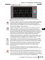
DEBUGGING AND
MONITORING
CHAPTER
10
In This Chapter
Monitor with Data View . . . . . . . . . . . . . . . . . . . . . . . .10-2
Change Value Dialog . . . . . . . . . . . . . . . . . . . . . . . .10-16
Using the Memory Editor . . . . . . . . . . . . . . . . . . . . . .10-20
Test Mode Operations for Debugging . . . . . . . . . . . .10-22
Trap Monitor . . . . . . . . . . . . . . . . . . . . . . . . . . . . . . .10-25
Stack Monitor (DL440 Only) . . . . . . . . . . . . . . . . . . .10-28
Trend View . . . . . . . . . . . . . . . . . . . . . . . . . . . . . . . .10-29
Check DirectSOFT 6 File Revision . . . . . . . . . . . . . .10-33
Chapter 10: Debugging and Monitoring
1
2
3
D
5
6
7
8
9
Monitor with Data View
Chapter 2, Quick Start, described how to edit a program and go
online with the PLC. There was also a discussion on how to monitor
the status of the program. This chapter will discuss more monitoring
and debugging features of DirectSOFT 6.
Using Data View
Using the Status to monitor a program is very useful. The Data
View window is more useful since you can do much more in one
view. The Data View window has more advantages, such as:
• View status of elements.
• Read and write data values.
• Multiple Data Views can be open at the same time.
• Since they “float”, they can be placed at convenient locations.
• Data View is also conveniently docked by default, and can be set to autohide by clicking on the push-pin. Multiple Data Views can be tabbed
together as one dockable or floating window.
• Use Data View to monitor the program all views (ladder, stage,
mnemonic) on the same screen.
10
11
2
13
4
A
B
C
D
• The Data View window can be saved by name.
• Data View windows are independent of projects, and can be used for
multiple projects.
Open a New Data View Window
10-2
A new Data View window can be opened in any one of three ways;
the menu bar Debug > Data View > New, the keyboard shortcut
Ctrl + Shift + F3 or the Data button on the Online toolbar.
By default, the Data
View windows are
assigned names
Data1, Data2, etc.
consecutively. This
name can be changed
for the current view
using the Options
dialog.
DirectSOFT 6 User Manual, 1st Edition
Chapter 10: Debugging and Monitoring
The following diagram is an example of a newly opened Data View.
A Closer Look
Data Format
Select
Edits
Mode
Format Size
Clear Edits
Write
Current Edit
to PLC
Write All
Edits to PLC
1
2
3
D
5
6
7
8
9
10
Edits Column
A closer look at Data View will show the basic components.
• Select Edits Mode Ҁ enables/disables the Edits column. When
the column is enabled, Edits can be written to the PLC. The Edits
column is not available when disabled.
• Data Format Ҁ change the format (bit, binary, Octal, decimal, etc.)
displayed in the Status column for a selected row.
• Format Size Ҁ choose the selected Data Format displayed in the
Status column(1, 16, 32, WORD, etc.).
• Clear Edits Ҁ this will clear all data entries from the Edits column.
DirectSOFT 6 User Manual, 1st Edition
1
2
3
4
A
B
C
D
10-3
Chapter 10: Debugging and Monitoring
1
2
3
D
5
6
7
8
9
• Write Current Edit to PLC Ҁ the data value for one element can
be entered in the Edits column and written to the PLC with this
button.
• Write All Edits to PLC Ҁ multiple data values can be entered in
the Edits column and written to the PLC.
Data View Options
10
11
2
13
4
A
B
C
D
10-4
The Data View window can be customized for a particular user or
users. To customize Data View, click on the Data View window, then
use View > Options on the menu bar, press the Options button on
the Offline toolbar or right-click in the Data View and choose
Options. The Options dialog will open with the Data View tab in view
as shown above.
The dialog will open with default selections checked in the General
Settings in the Display 1 tab. More settings are continued in the
Display 2 tab. Checking Col 1 shows display format may be
beneficial at times. This will show the display format to the right of
the element in the first column. Not all requirements are the same,
and experimenting with the General Settings will determine what
works best for you.
DirectSOFT 6 User Manual, 1st Edition
Select Bits for Display
Chapter 10: Debugging and Monitoring
The Bit Display Settings area to the right of the General
Settings, is only available under the Display 1 tab. There are three
selections for controlling or monitoring bits with the PLC in the Run
Mode, either one, two, all three or none can be selected
(enabled).
1
2
3
D
5
6
7
8
9
• Status Bits Ҁ when this is enabled, the status of the element will be
shown in the Status column if Status On is enabled.
• Pause Bits Ҁ enabling this will allow inputs (or other logic) to operate
while disabling selected outputs.
• Override Bits Ҁ selected I/O points in Data View can be turned
ON/OFF if this is enabled.
The diagram below shows what a Data View can look like when all
three Bit Display Settings are enabled. Notice that the outputs are
the only elements to have all three sets of data bit buttons in the
Edits column. Each group of bit setting buttons can have the
displayed indicator changed from the default to any one of twenty
selections.
10
NOTE: The buttons in the Edits column will only be displayed when the
PLC is in the Run Mode and Status is selected. Also, they will be disabled
for DirectNET links.
DirectSOFT 6 User Manual, 1st Edition
10-5
1
2
3
4
A
B
C
D
Chapter 10: Debugging and Monitoring
1
2
3
D
5
6
7
8
9
Click on the bit button to be changed and a selection window for
that button will appear as shown in the diagram below. Make a
selection, such as the light bulb, by clicking on it. The indicator will
appear in the button and also on the Data View.
Click on
Status On
button to
change the
indicator.
Indicator
selection
window.
10
11
2
13
4
A
B
C
D
10-6
Indicator is
in buttons
DirectSOFT 6 User Manual, 1st Edition
Chapter 10: Debugging and Monitoring
Data View Documentation Options
Next to the Display 2 tab is the Doc tab. Select this tab to set up
the documentation to be displayed on the Data View window.
Whatever documentation (Elements, Nicknames, etc.) is to be
displayed in the Element column is enabled or disabled here. The
current Data View window can also be renamed from Data1,
Data2, Data3, etc. to any name to better identify it. Enter the new
name for the current Data View in the Title field. The name
entered can contain up to 32 characters.
Enter new name here.
1
2
3
D
5
6
7
8
9
10
Apply Options
Notice the three boxes next to the Apply options to: circled in the
above diagram. These boxes are in view while the dialog is open.
Select the view the options are to be applied to when the OK
button is pressed.
DirectSOFT 6 User Manual, 1st Edition
10-7
1
2
3
4
A
B
C
D
Chapter 10: Debugging and Monitoring
Data View Mode Options
Next to the Doc tab is the Mode tab. The mode selections will
determine whether the data in the Status column will be Read Only
(no writes) or Read/Write. A Data View can be setup for Read Only
if changes to data will not be permitted by whoever is observing it.
Read/Write should be selected for monitoring and debugging a
program. Leave Safety enabled so the write operation can be
confirmed.
1
2
3
D
5
6
7
8
9
10
11
2
13
4
A
B
C
D
Make Data View Entries
10-8
The columns in a new Data View window are blank whenever it is
first opened. The entries are entered in the Elements column. The
type of entries that can be made are element references, memory
addresses or nicknames. For example, control relay C1 or Test
Output 1 are valid
entries. Also, R000
for a data register
or V1200 for a Vmemory location
can be entered.
The example here
shows elements
and a memory
location which have
been entered while
Online with Status
enabled.
DirectSOFT 6 User Manual, 1st Edition
Chapter 10: Debugging and Monitoring
It really doesn’t matter if entries are made in the Element column
with the PLC Online or Offline, Status On or Status Off. Entries can
be made with the PLC Offline, then it can be placed Online later to
monitor the program.
Whenever a Data View window is opened, it appears to the left of
the Ladder View (see the example on the facing page). Keep in
mind that the Data View can be repositioned and resized to make
room for a larger Ladder View like the example below. The Data
View position in the example may be radical, but it may be more
convenient for the user.
1
2
3
D
5
6
7
8
9
10
1
2
3
4
A
B
C
D
DirectSOFT 6 User Manual, 1st Edition
10-9
Chapter 10: Debugging and Monitoring
Data Format and Size
1
2
3
D
5
6
7
8
9
10
11
2
13
4
A
B
C
D
10-10
There are two small fields located in the top left-hand corner of the
Data View window. The one on the left is the Data Format field
which displays the element type when it is selected in the Element
column. If the selected element is a bit type, then Bit will be
displayed in the field. If desired, Bit can be changed to Binary by
clicking on the down arrow next to the field. A dialog will drop down
with the available selections to chose. The field to the right of the
Format field is the Data Format Size field. The size refers to the
data length. As an example, Bit is equal to 1 and Word is equal to
16 bits. The selection of the Data Format and Size is left up to the
programmer monitoring the program.
Data
Format Types
DirectSOFT 6 User Manual, 1st Edition
Bit changed to
Binary (16 bits)
Write the Edits
Chapter 10: Debugging and Monitoring
Debugging a program is not beneficial unless the user can change
an element or enter data in a memory location. Changes (edits)
are made in the Edits column. All of the edits are placed in a buffer
prior to writing them to the PLC. There are three buttons located at
the top of the Data View window which are associated with the
Edits column. These buttons are pointed out in the example below.
The Clear Edits button will clear everything out of the Edits buffer
so new edits can be entered. Single edits can be entered into
memory, such as a counter setpoint value. Simply enter the value
in the Edits column in the counter row. A single edit can also turn
on a control relay by clicking on the ON button for the relay. Once
both types of entries (edits) are made, click on the button with the
single arrow pointing to the PLC, Write to PLC. Multiple values or
control relays can also be written to the PLC. The entries or ON
buttons are selected as for the single edit. After the edits are
made, click on the button with four arrows pointing down at the
PLC. The edits will be written to the PLC one at a time.
Clear Edits
Write
Current Value
to PLC
Write Multiple
Values to PLC
1
2
3
D
5
6
7
8
9
10
WARNING: I/O points can be turned on by using the Override
buttons. Caution must be taken when forcing I/O to prevent accidental
harm to personnel and equipment.
DirectSOFT 6 User Manual, 1st Edition
1
2
3
4
A
B
C
D
10-11
Chapter 10: Debugging and Monitoring
Auto-increment
Auto-increment is a feature that can be used to enter elements
sequentially. For instance, if a group of control relays , C10, C11,
C12 and C13 are to be monitored, enter C10 then click on it again,
and then hold down Ctrl + Enter and control relays will be entered
until the Enter key is released. If there is an element that has been
entered previously in Data View, click on the element nickname or
reference, then use the Ctrl + Enter keys as mentioned above. The
elements will be entered in sequence below the starting point and
any elements that were below the start point will be pushed down
below that point.
1
2
3
D
5
6
7
8
9
Click on an
element, then
press Ctrl + Enter
to make sequential
entries.
10
11
2
13
4
A
B
C
D
Editing Entries
10-12
Editing the entries can only be accomplished by using the standard
keyboard shortcuts. Click on the element to be edited, then use
either Ctrl + C or Ctrl + X to copy or cut the element. Ctrl + V is
used to paste the element.
WARNING: Because Data View follows the conventions of spreadsheet
pasting, be aware that the pasting operation will overwrite any field
that has been selected prior to the paste. Consequently, it is preferred
to paste the data into an empty field.
Elements can be deleted from a Data View at any time. Select the
item by clicking on it, then either use the Delete key, Edit > Delete,
the Delete button on the Edit toolbar or right-clicking on the element
then select Delete in the pop-up menu. The deleted elements are
not placed on the clipboard, therefore lost.
DirectSOFT 6 User Manual, 1st Edition
Chapter 10: Debugging and Monitoring
An editing feature that can be useful is the ability to select more
than one item in Data View by using the method used to select
rungs in the Ladder View. Select the first item in the group, then
use the Shift + Arrow keys to mark a range of items either
horizontally or vertically. A more simple way to mark items is to
click on the first item in the range, and hold the button and drag
the mouse arrow over the rest of the last item to mark. The
marked items can then either be deleted, cut, copied or you can
change the Data Format or Data Size of the selected items all to
the same format or size.
Save the Data View Window
Once the Data View window has been setup for debugging and
monitoring a program, it is a good idea to save it so it can be
opened and used later. If the Debug toobar is displayed, click on
the Save button and the Save dialog will open. The Data View can
be named something else instead of the default ( Data1, Data2,
etc.), then save the Data View to the Projects folder by clicking on
the Save button. The Save dialog can also be opened by using
Debug > Data View > Save from the Menu bar. If a duplicate
Data View is needed, either use the Save As button on the Debug
toolbar or Debug > Data View > Save As from the Menu bar.
DirectSOFT 6 User Manual, 1st Edition
1
2
3
D
5
6
7
8
9
10
1
2
3
4
A
B
C
D
10-13
Chapter 10: Debugging and Monitoring
Using Pause Bits
1
2
3
D
5
6
7
8
9
A Pause Bit can be set for each output in the Data View window. By
setting the Pause Bit, the output status can be controlled when the
PLC transitions from Test Run to Test Program. The ability to hold
output states is useful, since it allows key system I/O points to be
maintained.
The Pause Bit is set to maintain the output status, and the Pause Bit
is turned off to allow the PLC to turn off the output on the transition
to Test Program mode.
The Pause Bit option is selected for outputs in the Data View
Options tab as seen below. The On/Off Pause buttons will then
show on the Data View.
10
11
2
13
4
A
B
C
D
To set the Pause Bit for an output, click on the respective pause
button (letter P). Click on the blank button to turn the pause feature
Off. When in the Off mode, the Pause Bit is not set and the output
will turn off on the transition to Test Program. The letter ‘P’ in the
Status column indicates the Pause Bit is set for that output.
Pause Bits set
10-14
DirectSOFT 6 User Manual, 1st Edition
Pause Buttons
Chapter 10: Debugging and Monitoring
Use Override Bits to Control I/O
(DL05/06/240/250-1/260/350/450 Only)
If your PLC supports Override Bits, they can be set for each input
and output using Data View. Setting these bits allows the status of
the input or output to be controlled by a programming device
instead of the field device wired to the I/O module. It is similar to
forcing an I/O ON or OFF.
To use the Override Bits, they must be enabled in the Data View
Options dialog. Select Override Bits just like the Pause Bits were
selected. Click on the Select Mode button at the top of the Data
View window to view the Override Bits buttons. Expand the Data
View window if necessary so the buttons will show.
Select
Mode button
1
2
3
D
5
6
7
8
9
10
Override Buttons
To set an Override Bit for an I/O point, click on the respective
Override button with the letter ‘O’. Clicking on the blank button will
turn the Override feature Off. The letter ‘O’ in the status column
indicates the Override Bit is set for that I/O point.
NOTE: Override bits clear out on a Program to Run transition.
DirectSOFT 6 User Manual, 1st Edition
1
2
3
4
A
B
C
D
10-15
Chapter 10: Debugging and Monitoring
1
2
3
D
5
6
7
8
9
Change Value Dialog
WARNING: Only authorized personnel should make changes to the
program elements or data values. Changes made while the PLC is in
Run Mode become effective immediately. Throughly consider the
impact of making changes in order to minimize the risk of personal
injury or damage to equipment.
The Data View window can be used to make dynamic changes to
I/O and change data values stored in memory. The status of an I/O
point is performed by using the dynamic edit buttons, and the data
values are changed by typing new values in the Edit column. Both
types of edit take effect only when they are written to the PLC.
Use the Change Value Dialog
10
11
2
13
4
A
B
C
D
Turning On/Off I/O points (only with Override bits set) and writing
data values to memory locations can also be accomplished by using
the Change Value dialog. When using this dialog, it is not
necessary to have Status on to make changes to the PLC, but it is a
good idea to be able to see the changes when they are made.
To open the Change Value dialog, either press the Change Value
button located on the Online toolbar, use Ctrl + Shift + F2 or, with
Status on and not in the Edit mode, double click on the element to
change. The following dialog will appear.
The dialog will open with either a default reference or the reference
that was double-clicked on showing in the Element window.
10-16
DirectSOFT 6 User Manual, 1st Edition
Chapter 10: Debugging and Monitoring
Specify an Element Reference or Nickname
Since nicknames and element references are used when editing a
program, they can also be used with the Change Value dialog. If
an element with a nickname is enabled in the program when the
dialog is opened, the nickname will appear in the Element field. An
element does not need to be enabled to open the Change Value
dialog. If the default reference (C0) is displayed when the dialog is
Specify the
element reference
or the nickname.
Current Value is
either ON or OFF.
The element
type will be
displayed here.
1
2
3
D
5
6
7
8
9
10
opened, either type in the element reference or the nickname that
is to be changed. The dialog will always open with the Current
Value displayed. The displayed element will either be On or Off.
The Current Value can also be a memory location. (see below).
The Element field
can have a memory
location.
The Curent Value
field will display the
data in memory.
The data types
are displayed
here.
DirectSOFT 6 User Manual, 1st Edition
1
2
3
4
A
B
C
D
10-17
Chapter 10: Debugging and Monitoring
Enter a New Value
1
2
3
D
5
6
7
8
9
To change the state (value) of a bit data type, such as a control
relay, enter the reference or nickname. The example diagram below
has C1 entered in the Element field. To change it from Off to On,
simply click the On under New. Like Data View, the new state will
not be written to the PLC until it is told to. Do this by pressing the
Write to PLC button. The Current Value will change to read On.
Change Current
Value to ON.
10
11
2
13
4
A
B
C
D
Current Value
now reads ON
NOTE: To force I/O, use the Override editor.
10-18
DirectSOFT 6 User Manual, 1st Edition
Press the Write
to PLC button.
Chapter 10: Debugging and Monitoring
To write to a V-memory location, type the memory location in the
Element field. The value in memory will appear in the current
value view. To change the value, enter it in the New field, then
press the Write to PLC button.The new value is written to the V-
Data will be
dynamically
displayed
here.
memory location. The value in the memory location will be
displayed under Current Value.
When an I/O reference or a memory location is entered in the
Element field, the status or value will be displayed in the New
value field as well as under the Current Value. By clicking on the
Read from PLC button, the Current Value and the New field will
be updated with the current status or data.
DirectSOFT 6 User Manual, 1st Edition
1
2
3
D
5
6
7
8
9
10
1
2
3
4
A
B
C
D
10-19
Chapter 10: Debugging and Monitoring
1
2
3
D
5
6
7
8
9
Using the Memory Editor
WARNING: Only authorized personnel should make changes to the
program elements or data values. Changes made while the PLC is in
Run Mode become effective immediately. Thoroughly consider the
impact of making changes in order to minimize the risk of personal
injury or damage to equipment.
Another debugging tool which DirectSOFT 6 features is the
Memory Editor. The Memory Editor can be used to view and
change data in a multiple of memory locations. This is especially
helpful for:
• Entering or changing values in V-memory or Data Registers for use as
constants, timer/counter presets, etc.
• Entering text strings into a block of V-memory or Data Registers.
Either press the Memory Editor (Memory) button located on the
Tools toolbar, use Tools > Memory Editor on the Menu bar or use
the keyboard shortcut, Ctrl + Y. The following diagaram is an
example of the Memory Editor.
10
11
2
13
4
A
B
C
D
Select the Locations to View
To use the Memory Editor, first use the Find button located in the
upper right-hand corner of the editor. A dialog will appear for the
entry of the memory address to begin the range to be viewed or
edited and press OK.
NOTE: The Memory Editor cannot be used to access bit registers (I/O as
registers or V-memory). For example, R600 is entered to access Timer 600
in a DL305 system, or V1000 to access Counter 0 actual value in a DL05
PLC.
10-20
DirectSOFT 6 User Manual, 1st Edition
Chapter 10: Debugging and Monitoring
Enter
memory
address for
start of range
to view.
Find
button
Entering V1000 for the memory range will display the alias CTA0.
The alias could have also been entered. Notice the Format area
where the default, BCD/Hex, has been automatically selected.
This is the proper format for the actual counter value. If the user
wishes to view it in a different format, simply click on one of the
formats shown to change the default. Also, the data size can be
selected in the same manner. How the data is viewed is strictly up
to the user. Any one of the sixteen data fields can be selected to
enter data. Once new data is entered in the data field, press the
Write to PLC button to update the PLC. The Memory Editor will
not update the data being viewed automatically. To view data
being updated, press the Read from PLC button. Press this
button each time you wish to view data being updated.
There may be times when a block of memory will be need to be
setup with data and saved for use during debugging. Simply enter
the data in each data field to be written to the PLC. After entering
the data, press the Write to Disk button to save the data. Use the
Read from Disk to re-enter the data in memory.
Read from Disk and Write to Disk buttons.
Read from PLC and Write to PLC buttons.
Data fields
DirectSOFT 6 User Manual, 1st Edition
1
2
3
D
5
6
7
8
9
10
1
2
3
4
A
B
C
D
10-21
Chapter 10: Debugging and Monitoring
1
2
3
D
5
6
7
8
9
Test Mode Operations for Debugging
Select Test Mode
DirectLOGIC PLCs support most Test Mode operations which
DirectSOFT 6 features (only the DL440 and DL450 support all Test
Mode operations). Test Mode operations can be a useful tool for
debugging programs. Have Status on when using the Test Mode
feature to assist with debugging your program. Enter the Test Mode
from either the Run Mode or Program Mode, by either pressing the
Mode button on the Online toolbar, using PLC > PLC Modes on the
Menu bar or using the keyboard shortcut Ctrl + Shift + R. The PLC
Modes window shown below will appear. Select Test then OK.
10
11
2
13
4
A
B
C
D
10-22
If the PLC is in the Run Mode when Test is selected, the CPU will
still be scanning the program and Test RUN will be displayed in the
PLC Mode Indicator at the bottom of the program display window.
Stop PLC
Scan button
To use the Test Operations, open the Test Operations window by
selecting the Test button from the Debug toolbar. The PLC must be
in the Test Program Mode. The PLC can be placed in the Test
Program Mode from the above window by clicking on the Stop PLC
Scan button which will be the only button highlighted in the window
when in Test Run. The Test Program Mode can also be entered
from the Program Mode by opening the PLC Modes window and
selecting Test.
DirectSOFT 6 User Manual, 1st Edition
Chapter 10: Debugging and Monitoring
Test Program Operations
There are four operations available for all DirectLOGIC PLCs in
the Test mode only:
1. Start PLC Scan Ҁ this places the PLC into the Test Run mode
and will start the execution of the PLC. The PLC will continue
executing until the Stop PLC Scan button is pressed.
2. Stop PLC Scan Ҁ this places the PLC into the Test Program
mode which will stop the execution of the PLC.
3. Single Scan Ҁ will start the execution of the PLC program for
one scan, and then stop execution of the program.
4. Multiple Scans Ҁ is used to execute the PLC program for a
given number of scans. Use this when in the Test mode. Enter
the number of scans in the entry field of the pop-up window,
and press OK. The PLC will change to Test Run mode until the
given number of scans have been executed at which time the
PLC will change to Test Program mode. This item is only
available when the PLC is in the Test mode.
Two additional Test Operations are only available for the DL440
and DL450 PLCs, they are:
Breakpoint Ҁ specify an instruction address at which to stop the
PLC. Pressing OK will execute the program until it reaches the
address, and then the PLC is placed into Halt Mode.
Use this in the Test Program mode, Breakpoint will place the PLC
into Test Run mode until the specified address is executed then
returns the PLC to Test Halt mode. Use Breakpoint only in the test
mode.
BREAK Instruction Ҁ this instruction changes the operational
mode of the CPU from Run to the Test Program mode. The Break
instruction allows V-memory and image register data to be
retained where it would normally be cleared with the STOP
instruction or a normal Run to Program transition. (see the DL405
User Manual).
DirectSOFT 6 User Manual, 1st Edition
1
2
3
D
5
6
7
8
9
10
1
2
3
4
A
B
C
D
10-23
Chapter 10: Debugging and Monitoring
The Test Operations Window
1
2
3
D
5
6
7
8
9
When in one of the Test Modes, the Test Operations window can be
opened with the Test button located on the Debug toolbar or by
using Debug > Test Mode Operations from the Menu bar, and the
following window will appear. The window has six buttons to be used
for Test Operations mentioned on the previous page. The buttons
available for each test mode will be highlighted. Only one button,
Stop PLC Scan is available in Test Run, and two buttons are only
available for use with the DL440/450 PLCs, Single Step and
Breakpoint.
Breakpoint
Start PLC Scan
Single Step
Stop PLC Scan
Single Scan
Multiple Scans
10
11
2
13
4
A
B
C
D
10-24
DirectSOFT 6 User Manual, 1st Edition
Trap Monitor
Chapter 10: Debugging and Monitoring
Access the Trap Monitor
1
2
3
D
5
6
7
8
9
The DL06, DL250-1, DL260 and DL450 uses an additional
diagnostic tool called a Trap Monitor. The Trap Monitor is used to
trap (capture) element data at a specific address rather than after
a scan. The Trap Monitor can be a useful tool if you wish to look at
some ladder logic in the Test Run mode. An example might be to
check a math routine to see if it is working properly.
To use the Trap Monitor, either press the Trap button located on
the Debug toolbar, if it is displayed, or use Debug > Trap Monitor
on the Menu bar. The Trap Monitor can only by used in the Test
Run Mode. If the PLC is not in Test Run, a message will appear to
ask you if it is safe to switch the PLC to Test Run mode. Select the
“Switch to....” button. Another dialog will appear and ask if you are
sure it’s okay to switch to Test Run. Once the PLC is placed in
Test Run, the dialog shown below will appear. A definition of the
basic components will be helpful before using the Trap Monitor.
Enable trap pushpins shown in
disabled position.
This area is read
only and will display
the data for the
trapped element.
This is the address
of the trapped
element (not the
rung number).
10
The element
trapped at the
above address.
Press this button
to change the
format of the
Element Value to
be read.
The Trap Monitor can be used as shown above by entering the
element address and the element reference to read the data in the
read only area of the dialog. The address can be left alone while the
element reference is being changed if it is necessary to read the
Element Value at that address. Or, the Address can be incremented
or decremented leaving the Element Value alone to check the data
at different addresses.
DirectSOFT 6 User Manual, 1st Edition
1
2
3
4
A
B
C
D
10-25
Chapter 10: Debugging and Monitoring
1
2
3
D
5
6
7
8
9
10
11
2
13
4
A
B
C
D
10-26
Another way to use the Trap Monitor is to enable the two Trap pushpins. When the pins are enabled, the Address can be incremented
or decremented while observing the Element located at the new
Address. The read-only data will also change.
If you want to “step” through a program area to check the data in
V-memory locations, just leave the Trap Monitor dialog as shown
above, then place the ladder program cursor over the element (box)
with the memory reference in it. You can then read the data in the
read only area.
DirectSOFT 6 User Manual, 1st Edition
Use with Data View
Chapter 10: Debugging and Monitoring
The Trap Monitor is normally used in combination with one or
more Data Views so the inputs and outputs of the Ladder Logic or
Stage program can be controlled. The Trap Monitor is useful to
look at math operations in a program. The format for the values
being read can be specified (Decimal, Hex or Octal). Press the
button in the lower right-hand corner of the dialog to open another
dialog to set the format.
NOTE: The Trap Monitor feature is not available to use with the DL05.
1
2
3
D
5
6
7
8
9
10
1
2
3
4
A
B
C
D
DirectSOFT 6 User Manual, 1st Edition
10-27
Chapter 10: Debugging and Monitoring
1
2
3
D
5
6
7
8
9
Stack Monitor (DL440 Only)
Access the Stack Monitor
The Stack Monitor monitors PLC accumulator and data stack. Either
use the Debug->Test Mode Operations->Breakpoint dialog or the
BREAK instruction to monitor the PLC accumulator and data stack
at a specific address.
Access the Stack Monitor by either pressing the Stack button
located on the Debug toolbar or by selecting Debug > Stack
Monitor from the Menu bar. This feature is used most frequently
with segments of programming which require debugging math
operations.
10
11
2
13
4
A
B
C
D
10-28
DirectSOFT 6 User Manual, 1st Edition
Chapter 10: Debugging and Monitoring
Trend View
As mentioned in Chapter 7, Trend View is used to visually monitor
the values of DL controller data elements over time. The Trend
View can monitor any readable numeric location or any readable
bit location or any constant value.
The Trend View logs the values of the controller elements on each
pane of the Trend. Those values are displayed on a moving graph.
The Trend View also provides a historical mode which lets the
programmer view all of the data that is currently stored for each of
the data points on the display. The logged data values can also be
exported to a CSV file for importing into a third-party application
for further research.
A new (empty) Trend View can be created by selecting Debug >
Trend View > New from the Menu, or clicking the Trend button on
the Online toolbar. Enter the number of Panes in the Number of
Panes field or use the Up or Down arrow to set the value. Click
the OK button to accept or the Cancel button to abort.
NOTE: Refer to the DirectSOFT 6 help file for more information on
configuration options and features of Trend View.
Using the Trend View
10
Once a Trend View has been created and its display options have
been configured, the Trend will begin collecting data for each of
the controller elements on each of the panes and displaying the
data in graphical form as seen below.
DirectSOFT 6 User Manual, 1st Edition
1
2
3
D
5
6
7
8
9
1
2
3
4
A
B
C
D
10-29
Chapter 10: Debugging and Monitoring
Some things to be aware of when using Trend Views:
1
2
3
D
5
6
7
8
9
• Discrete points, integer values and real values are placed in separate
panes.
• Variables are graphed using solid lines.
• Constants are graphed using dotted horizontal lines.
• Red vertical lines indicate a loss of communication.
• Blue vertical lines indicate communication is re-established.
The Crosshair Cursor
10
11
2
13
4
A
B
C
D
The crosshair cursor is displayed anytime the mouse cursor moves
over any of the panes in a Trend View. The crosshair provides a
visual reference when comparing values displayed on the Panes of
a Trend. If there are multiple Panes in the Trend View, the vertical
bar of the crosshair will extend through all of them.
Using the CTRL key and the scroll wheel on the mouse will put the Trend
View into Historical Mode and zoom into or out of the area under the center
of the crosshair as follows:
• CTRL + scolling upward will zoom into the area by decreasing the Time
Scale
• CTRL + scrolling downward will zoom out of the area by increasing the
Time Scale.
Left-clicking the mouse will take a snapshot of all the values on all
the Panes on the Trend at the time where the crosshair was located,
then present the data on a snapshot dialog.
Clicking the Copy Contents to Clipboard button will copy the data
displayed on the snapshot dialog to the Windows clipboard, which
can then be pasted into any other Windows application for further
processing.
10-30
DirectSOFT 6 User Manual, 1st Edition
Chapter 10: Debugging and Monitoring
1
2
3
D
5
6
7
8
9
Looking at the above Trend View, notice the following menu
options at the top of the View.
Trend View Options - opens the Trend View Options dialog to specify the
controller elements that will be included in the Trend and to choose how
those elements will be displayed on the Trend. When this button is
clicked, the last pane that had focus will be selected (highlighted) when
the Trend View Options menu comes up.
Toggle Historical Mode - stops the real-time (live) update of the trend
displays and adds a scroll bar to the bottom of the trend panel that
allows the user to scroll backwards in time through all of the data that is
currently stored for each of the data points on the displays. The data
gathering for each data point on the trend displays will continue while the
Trend View is in historical mode. When the Trend View is in historical
mode the tab name will have the word [HISTORICAL] added to it.
10
Clicking the button again will re-enable the real-time (live) update of the
trend displays and the trend graphs will be updated with all of the data
that was gathered while the displays were in historical mode.
Export Range - is used to export the values that are currently stored for
each data point on the trend. All of the accumulated data points or only
the data points between two user-selected time stamps can be exported.
Synchronize with Other Trend Views - is used to synchronize the time
frame and the starting time stamp of multiple Trend Views so that all
synchronized views will display the same start time and the same
amount of time.
Click the Sync button to display a list of the available Trend Views.
Select the Views from the list that are to be synchronized with the current
view then click the Synchronize button.
1
2
3
4
A
B
C
D
Begin Recording - click this button to begin the recording session. The
button face will change from a red circle to a black square with Stop as its
new name and the word [RECORDING] will be displayed in the dialog's
tab. Clicking this button again will stop the recording and a Save As dialog
will prompt for the filename in which to save the recorded data.
DirectSOFT 6 User Manual, 1st Edition
10-31
Chapter 10: Debugging and Monitoring
1
2
3
D
5
6
7
8
9
10
11
2
13
4
A
B
C
D
10-32
Pause Recording - stops recording data while the button is depressed.
The button will appear depressed and the word [RECORDING - PAUSED]
will be displayed in the dialog's tab. Click the button again to continue
recording data or click the Cancel button to stop the recording session
completely.
Time Scale - sets the overall amount of time to be
displayed in all of the panes.
The Time Scale can be set to the following:
- 500ms
- 1 Second
- 5 Seconds
- 10 Seconds
- 20 Seconds
- 30 Seconds
- 45 Seconds
- 1 Minute (default)
- 2 Minutes
- 5 Minutes
- 7 Minutes
- 10 Minutes
- 30 Minutes
- 1 Hour
The Time Scale value is set by the following methods:
• Clicking on the Time Scale icon at the desired interval location
• Clicking on the Time Scale icon at the desired location then use the
arrow keys or the mouse scroll wheel to decrease or increase the value
• Clicking and holding the slider and dragging left to decrease and right to
increase the value
DirectSOFT 6 User Manual, 1st Edition
Chapter 10: Debugging and Monitoring
Check DirectSOFT 6 File Revision
DirectSOFT 6 has a quick and easy method of looking at the
various versions of the files which comprise the software. This
feature may never be used, however, this may be useful in the
future as additional features are added in upgrade packages, new
products, etc.
Open the Version Browser by double-clicking on Version located
under Utilities on the DSLaunch menu tree.
Double-click
here
1
2
3
D
5
6
7
8
9
10
TIP: A simple way to check the DirectSOFT 6 version is to open a project
program and select Help > About.
DirectSOFT 6 User Manual, 1st Edition
1
2
3
4
A
B
C
D
10-33
Chapter 10: Debugging and Monitoring
Notes:
1
2
3
D
5
6
7
8
9
10
11
2
13
4
A
B
C
D
10-34
DirectSOFT 6 User Manual, 1st Edition