1
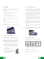
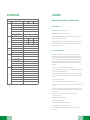
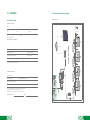
User Manual
Replus-250 Replus-250A Replus-250B
U.S.A
Add: 301 Howard St, Suite 850, San Francisco, CA 94105.
T: +1 415 852 7418
Australia
Add: 18 Corporate Blvd. Bayswater, VIC 3153, Australia
T: +61 481 251 275
Europe
Add: Renesola Deutschland GmbH, Lyoner Strasse 15, 60529 Frankfurt/M, Germany
T: +49 69 663 786 9-0
APMEA & China
Add: F-15,Manpo Intl. No.500 WestYan’an Rd, Shanghai, China 200050
T: +86 21 62809180
Web: www.renesola.com
E: [email protected]
CONTENT
COMPANY PROFILE
1. INTRODUCTION
01
01
Prefix
01
1.1 Grid-tied PV System
01
1.2 How to Use This Manual
01
2. SAFETY INSTRUCTIONS
02
3. FCC COMPLIANCE
02
4. INSTALLATION
03
5. COMMISSIONING
07
6. OPERATING INSTRUCTIONS
07
7. TROUBLESHOOTING AND MAINTENANCE
08
8. SPECIFICATIONS
10
9. WARRANTY
11
10. CONTACT US
13
11. APPENDIX
14
11.1 Warranty Card
14
11.2 Examples of connection diagram
15
11.3 Connection Map
17
COMPANY PROFILE
ReneSola has been listed on New York Stock Exchange (NYSE:SOL) in 2008. Its products have been
delivered around the world since its establishment. It has multiple locations worldwide, with
sales and operations facilities in the United States, Europe, and Asia-Pacific regions. ReneSola has
a strong focus on helping customers meet delivery schedules, using high quality photovoltaic
modules and PV micro grid-tied inverter.
1. INTRODUCTION
Prefix
Thank you for selecting the ReneSola Micro Replus-250/ Replus-250A/B inverter. We are certain
our products will meet your project and business needs. We appreciate your feedback regarding
our products, and invite you to contact us at [email protected] or www.renesola.com for
more information.
1.1 Grid-tied PV System
Grid-tied PV systems consist of PV panels, grid-tied inverters, junction boxes, etc. The power
generated by the micro inverter is converted from DC to AC energy and feedback to the grid,
through net metering, using the Micro Replus-250/ Replus-250A/B .
1.2 How to Use This Manual
This manual provides detailed product information and installation instructions for the
Replus-250/ Replus-250A/B micro-inverter. Please read this manual prior to installation and
operation.
01
2. SAFETY INSTRUCTIONS
Warning: Please Read This Manual Before Installation. Any Damage To The Product Due To
Not Following This Manual Is Not Covered By The Warrantee. All The Installation Should Be
Done By A Certified Electrician. Besides The Cable Connectors, Nothing Else On Or In
Microinverter Should Be Modified.
All Installations Should Follow The Local Electriccodes. The Replus-250/ Replus-250A/B Does Not
Include Components That Can Be Served By Customers. Opening Or Attempting To Modify Or
Change The Construction Or Design Of The Microinverter Shall Void The Warranty. Please Contact
Authorized Service Agents For Any Service Work.
Replus-250/ Replus-250A/B Is A Grid-tied Solar Inverter. It May Require Approval From Local
Utility Company Prior To Grid Inter Connection.
4. INSTALLATION
Warning: Be Aware That Installation Of This Equipment Includes Risk Of Electric Shock.
Normally, Grounded Conductors Maybe Ungrounded And Energized When A Ground Fault
Is Indicated.
Parts Included
In addition to the Replus-250/ Replus-250A/B micro inverters, PV modules, rack, and associated
hardware, you’ll need the Replus-250/ Replus-250A/B installation kit. This kit includes the
following items:
• Installation fixed screws
• Grounding fixed washers
• User manual
• Warranty Terms and Warranty Card
3. FCC COMPLIANCE
Other Required Parts And Tools
This equipment has been tested and found to comply with the limits for a Class B digital device,
pursuant to part 15 of the FCC Rules. These limits are designed to provide reasonable protection
against harmful interference in a residential installation. This equipment can radiate energy from
radio frequencies and, if not installed and used in accordance with the instructions, may cause
harmful interference with radio communications. If this equipment does cause harmful
interference to radio or television reception, which can be determined by turning the equipment
off and on, the user is encouraged to attempt to correct interference by taking one or more of
the following measures:
In addition to your PV array and its associated hardware, you will need to provide the following:
• Reorient or relocate the receiving antenna.
• Increase the separation distance between the equipment and the receiver.
• Connect the equipment to an outlet on a circuit different from that to which the receiver is
connected.
• Consult the dealer or an experienced radio/TV technician for help.
Changes or modifications not expressly approved by the party responsible for compliance may
void the user’s authority to operate the equipment.
• Junction box
• Continuous grounding wire
• Number 2 Phillips screwdriver
• Sockets and wrenches for mounting hardware
• Torque wrench
• Mounting hardware suitable for module rack
Lightning Surge Suppression
Lightning does not actually need to strike the equipment or building where a PV system is
installed to cause damage. Often, a strike nearby will induce surges in the electrical grid that can
potentially exceed maximum voltages and damage equipment. The Replus-250/ Replus-250A/B
has integral surge protection, greater than most string inverters. However, if the surge has
sufficient energy, the protection built into the Replus-250/ Replus-250A/B can be exceeded, and
the equipment can be damaged.
The ReneSola Limited Warranty does not cover “acts of God” such as lightning strikes, and since
lightning strikes can occur any where, it is recommended to install surge protection as part of any
solar installation. Installation of surge protection devices should follow vendor instructions.
02
03
Installation Procedure
Warning: Do Not Connect Replus-250/ Replus-250A/B To The Utility Grid Or Energize The Ac
Circuit(S) Until You Have Completed All Of The Installation Procedures As Described In The
Following Sections.
Installing the Replus-250/ Replus-250A/B micro inverter System involves several key steps:
1. Attaching the Replus-250/ Replus-250A/B micro inverter to the rack.
2. Connecting the Replus-250/ Replus-250A/B micro inverter wiring harnesses.
3. Measuring service and installing the AC branch circuit junction box.
Warning: Only Use Electrical System Components Approved For Wet Locations.
4. Grounding the system.
5. Completing the Replus-250/ Replus-250A/B micro inverter installation and connecting the PV
modules.
The finished system should be similar as in the diagram. Detailed installation steps are listed in the
following section.
Step 2 - Connect the Replus-250/ Replus-250A/B Cable
Each Replus-250/ Replus-250A/B comes with one 3-pin bulkhead receptacle (or short pigtail) and
one 57-inch AC wire harness with multi-pin connectors. (The DC input wires are approximately six
inches long and are terminated with single pole connectors.) The AC connectors are oppositely
sexed, so that multiple inverters can be connected to form one continuous AC branch circuit.
1. Orient the first Replus-250/ Replus-250A/B in each branch with its male connector facing the
junction box. The junction box AC interconnect cable has a female connector. The Replus-250/
Replus-250A/B can be mounted with either side facing up to accommodate cable routing.
Connect the first Replus-250/ Replus-250A/B to the AC interconnect cable.
2. Plug the AC connector of the first Replus-250/ Replus-250A/B into the connector of the next
Replus-250/ Replus-250A/B, and so forth, to form a continuous AC circuit. Please check the
Replus-250/ Replus-250A/B rating label for the maximum allowable number of Replus-250/
Replus-250A/B’s on one AC circuit.
Warning: Do Not Exceed The Maximum Number Of Replus-250/ Replus-250a/b’s In An Ac
Branch Circuit, As Displayed On The Unit-rating Label. Each Replus-250/ Replus-250a/b Ac
Branch Circuit Must Be Sourced From A Dedicated Branch Circuit Protected By A 15a
Maximum Breaker.
3. Install a protective end cap on the open AC connector of the last Replus-250/ Replus-250A/B in
the AC branch circuit.
Warning: Make Sure Protective End Caps Have Been Installed On All Unused Ac Connectors.
Unused Ac Replus-250/ Replus-250A/B Wire Harness Connectors Are Live When The System
Is Energized By The Utility System.
Step 1 - Attach the Replus-250/ Replus-250A/B to the Rack
1. Mark the approximate centers of each PV module on the rack system. Evaluate the location of
the micro inverter with respect to the PV module junction box or any other obstructions.
Warning: Allow A Minimum Of 0.75 Inches Between The Top Of The Roof And The Bottom Of
The Replus-250/ Replus-250a/b. We Also Recommend That You Allow 0.5 Inches Between The
Back Of The Pv Module And The Top Of Replus-250/ Replus-250a/b. Do Not Mount Replus-250/
Replus-250a/b In A Location That Allows Long-term Exposure To Direct Sunlight.
2. If using grounding washers to ground the micro inverter chassis to the PV module rack, choose
a grounding washer that is approved for the rack manufacturer. Install a minimum of one
grounding washer per micro inverter. Tear down barcode from inverter, paste the barcode into
the “Connection map”. Torque the micro inverter fasteners to the values listed below.
1/4” mounting hardware – 45 in-lbs minimum
5/16” mounting hardware – 80 in-lbs minimum
3. Mount one micro inverter at each of these locations using hardware
recommended by your module rack vendor. Mounting slots on the micro
inverter are 0.33 inches in diameter. Maximum bolt size is 5/16 inch.
The two slots on the micro inverter are 4 inches apart
04
Step 3 - Install the AC Branch Circuit Junction Box
1. Measure service entrance conductors to confirm AC service at the site. Acceptable ranges are
shown in the table below:
240 Volt AC Split Phases
208 Volt AC Three Phases
L1 to L2
211 to 264 Vac
L1 to L2
183 to 229 Vac
L1, L2 to neutral
106 to 132 Vac
L1, L2 to neutral
106 to 132 Vac
230 Volt AC Single Phase
L1 to L2
200 to 270 Vac
2. Mount the adapter plate at a suitable location on the PV rack system (typically at the end of a
row of modules).
3. Install an appropriate junction box with the adapter plate.
4. Connect the open wire end of the AC interconnect cable into the junction box using an
appropriate cable.
05
Step 4 – Ground the System
Each Replus-250/ Replus-250A/B comes with a ground clip that can accommodate a 6-8 AWG
conductor. The rack and module could be grounded to this conductor using a crimp connection.
An alternative method would be to connect the Replus-250/ Replus-250A/B to the grounded rack
using a grounding washer approved for the rack.
5. COMMISSIONING
Warning: Connectreplus-250/ Replus-250a/b To The Electrical Utility Grid Only After
Receiving Prior Approval From The Utility Company.
Warning: Be Aware That Only Qualified Personnel Must Connect Replus-250/
Replus-250a/b To The Electrical Utility Grid.
Warning: Ensure That All Ac And Dc Wiring Is Correct. Ensure That None Of The Ac And Dc
Wires Are Pinched Or Damaged. Ensure That All Junction Boxes Are Properly Capped And Not
Exposed.
Following these steps to commission the Replus-250/ Replus-250A/B PV system:
Step 5 - Connect the PV Modules and Complete the connection map
Connect the PV Modules
Completely install all Replus-250/ Replus-250A/B and system inter-wiring connections prior to
installing the PV modules.
1. Mount the PV modules above the corresponding Replus-250/ Replus-250A/B. Each
Replus-250/Replus-250A/B comes with two oppositely sexed DC connectors.
2. First connect the positive DC wire from the PV module to the negatively marked DC connector
(male pin) of the Replus-250/ Replus-250A/B. Then connect the negative DC wire from the PV
module to the positively marked DC connector (female socket) of the Replus-250/
Replus-250A/B. Repeat for all remaining PV modules using one Replus-250/ Replus-250A/B for
each module.
1. Turn ON the AC disconnector or circuit breaker on each Replus-250/ Replus-250A/B AC branch
circuit.
2. Turn ON the main utility-grid AC circuit breaker. Your system will start producing power after a
few minutes wait time.
3. The Replus-250/ Replus-250A/B will start to send performance data over the power lines using
power line communication (PLC) to the MRG. The time required for each Replus-250/
Replus-250A/B in the system to communicate to the MRG will vary with the number of
Replus-250/ Replus-250A/B’s in the system.
6. OPERATING INSTRUCTIONS
Complete Connection Map
The Replus-250/ Replus-250A/B Connection Map is a diagrammatic representation of the
physical location of each Replus-250/ Replus-250A/B in your PV installation. The virtual array in
the ReneSola micro inverter gateway, MRG, is created from the map you create.
Each Replus-250/ Replus-250A/B has a serial number, enter this serial number into the MRG
according with barcode of “connection map”, so MRG can correspond with micro inverter and
internet.
The Replus-250/ Replus-250A/B is powered on when sufficient DC voltage from the module is
applied. The status LED will start flashing after sufficient DC power is applied as an indication that
the Replus-250/ Replus-250A/B is live.
Status: standby
The LED light is on by 2 seconds, and off by 2 seconds.
Status: producing power
The LED light is on by 1 second, and off by 1 second.
Status: producing power and communicating with MRG
The LED light is on by 0.5 second, and off by 0.5 second.
06
07
7. TROUBLESHOOTING AND MAINTENANCE
Warning: Do Not Attempt To Repair The Replus-250/ Replus-250a/b; It Contains No
User-service Able Parts. If Troubleshooting Methods Fail, Please Return The Replus-250/
Replus-250a/b To Your Distributor For Maintenance.
Disconnecting a Replus-250/ Replus-250A/B from the PV Module
To ensure the Replus-250/ Replus-250A/B is not disconnected from the PV modules under load,
adhere to the following disconnection steps in the order shown:
1. Disconnect the AC by opening the branch circuit breaker.
Warning: Never Disconnect The Dc Wire Connectors Under Load. Ensure That No Current Is
Flowing Inthe Dc Wires Prior To Disconnecting. An Opaque Covering Maybe Used To Cover
The Module Prior To Disconnecting The Module.
2. Disconnect the first AC connector in the branch circuit.
Warning: Always Disconnect Ac Power Before Disconnecting The Pv Module Wires From
Replus-250/ Replus-250a/b. The Ac Connector Of The First Replus-250/ Replus-250a/b In A
Branch Circuitis Suitable As A Disconnecting Means Once The Ac Branch Circuit Breaker In
The Load Center Has Been Opened.
4. Using a DC current probe, verify there is no current flowing in the DC wires between the PV
module and the Replus-250/ Replus-250A/B.
Warning: Replus-250/ Replus-250a/b Is Powered By Dc Power From The Pv Modules. Make
Sure You Disconnect The Dc Connections And Reconnect Dc Power To Watch For The Six
Short Led Blinks One Minute After Dc Is Applied.
3. Cover the module with an opaque cover.
5. Care should be taken when measuring DC currents, as most clamp-on meters must be zeroed
first and tend to drift with time.
6. Disconnect the PV module DC wire connectors from the Replus-250/ Replus-250A/B.
7. Remove the Replus-250/ Replus-250A/B from the PV array rack.
LED indication of error
• Error report: AC or DC fault
The LED light is on by 4 seconds, and off by 4 seconds.
• Error report: GFDI fault
The LED light stays on.
Troubleshooting an Inoperable Replus-250/ Replus-250A/B
To troubleshoot an inoperable Replus-250/ Replus-250A/B, follow the steps in the order shown:
1. Check the connection to the utility grid. Verify that the utility voltage and frequency are within
allowable ranges shown in the label of the Replus-250/ Replus-250A/B.
2. Verify utility power is present at the inverter in question by removing AC, then DC power.
Never disconnect the DC wires while the Replus-250/ Replus-250A/B is producing power.
Re-connect the DC module connectors, and then watch for the LED blinks.
3. Check the AC branch circuit interconnection harness between all the Replus-250/
Replus-250A/B’s. Verify that each inverter is energized by the utility grid as described in the
previous step.
4. Make sure that any AC disconnects are functioning properly and are closed.
5. Verify the PV module DC voltage is within the allowable range shown in the label of the
Replus-250/ Replus-250A/B.
6. Check the DC connections between the Replus-250/ Replus-250A/B and the PV module.
7. If the problem persists, please contact ReneSola customer support.
Warning: Do Not Attempt To Repair The Replus-250/ Replus-250A/B; It Contains No
User-serviceable Parts. If Troubleshooting Methods Fail, Pleasere Turn The Defective
Replus-250/ Replus-250A/B To Your Distributor For Maintenance.
08
Installing a replacement Replus-250/ Replus-250A/B
1. Attach the replacement Replus-250/ Replus-250A/B to the PV module rack using hardware
recommended by your module rack vendor. If you are using grounding washers (e.g., WEEB) to
ground the chassis of the Replus-250/ Replus-250A/B, the old grounding washer should be
discarded and a new grounding washer must be used when installing the replacement
Replus-250/ Replus-250A/B. Torque the Replus-250/ Replus-250A/B fasteners to the values
listed below:
1/4” mounting hardware – 45 in-lbs minimum.
5/16” mounting hardware – 80 in-lbs minimum.
2. If you are using a grounding electrode conductor to ground the Replus-250/ Replus-250A/B
chassis, attach the grounding electrode conductor to the Replus-250/ Replus-250A/B ground
clamp.
3. Connect the AC cable of the replacementReplus-250/ Replus-250A/B and the neighboring
Replus-250/ Replus-250A/B to complete the branch circuit connections.
4. Complete the connection map and connect the PV Modules
1) Complete the connection map.
2) Each Replus-250/ Replus-250A/B has a removable serial number label located on the
mounting plate. Enter this serial number into the MRG, and correspond it to a number in the
connection map.
3) Connect the PV Modules.
4) Completely install all Replus-250/ Replus-250A/B and all system inter-wiring connections
prior to installing the PV modules.
a) Mount the PV modules above their corresponding Replus-250/ Replus-250A/B. Each
Replus-250/ Replus-250A/B comes with one male and one female DC connector.
b) First connect the positive DC wire from the PV module to the negatively marked DC
connector (male pin) of the R Replus-250/ Replus-250A/B. Then connect the negative DC
wire from the PV module to the positively marked DC connector (female socket) of the
Replus-250/ Replus-250A/B.
Repeat for all remaining PV modules using one Replus-250/ Replus-250A/B for each module.
09
9. WARRANTY
8. SPECIFICATIONS
Technical Specifications
Model
Replus-250A
Input (DC)
Max. DC Voltage (V)
55
Maximum input short circuit current (A)
14
MPPT efficiency
>99.5%
Max. Units per Branch Circuit
15
Nominal AC Power (W)
225
Nominal AC Voltage (V)
Protection
240
208
Warranty Time Start: From the date of bill of lading.
230
186 ~ 228
200 ~ 270 *
AC Power Frequency / Range (Hz)
59.3 ~ 60.5
59.3 ~ 60.5
45.5 ~ 54.5 *
<4%
Power Factor (cosφ)
>0.95
Peak. Efficiency
96.3%
CEC Efficiency
95.0%
Power Consumption at Night (W)
<0.17
Over/ Under Voltage Protection
Yes
Over/Under Frequency Protection
Yes
Anti-Islanding Protection
Yes
Over Current Protection
Yes
Reverse DC Polarity Protection
Yes
Overload Protection
Yes
Degree of protection
NEMA6 / IP66
Relative Humidity
General Data
Warranty Period: 25-year limited warranty period.
211 ~ 264
Environment Temperature
Display
Warranty terms of Micro Replus™ Grid-Tied Microinverter
Warranty Conditions
Nominal AC Voltage Range (V)
THD (at Nominal Output)
Efficiency
Replus-250
22 ~ 45
MPPT DC Voltage Range(V)
Output (AC)
Replus-250B
270
Max. PV-Generator Power (Wp)
-40˚c ~ +65˚c
0 ~ 95%
LED Light
Communication way
PLC (Power Line Communication)
Dimensions (WxHxD)
230*138*35 mm / 9.06*5.44*1.38 inch
Weight
2.0 kg / 4.4 lbs
Warranty
25 years limited warranty
* Detailed parameter please see local grid standard, inverter can match local grid standard automatically.
Warranty Evidence:The bill of lading date, product(s) serial number(s), and product(s) model
number(s), and a completed warranty card.
Scope: Any damages occurring within the WARRANTY PERIOD will be evaluated by ReneSola
authorized service partners and qualified ReneSola employees, who will define the scope and
responsibility taking into account.
Terms of the Product Warranty:
This warranty is provided in an effort to improve service and peace-of-mind to end users of
ReneSola microinverters. All ReneSola authorized Dealers and Distributors are required to
complete a ReneSola Warranty Card in the event of a claim, at which point ReneSola will either
(a) replace or repair any products or parts of the product during the Warranty Period or (b) the
original cost of the Micro Replus inverter, proven defective in design or manufacturing, will be
refunded. ReneSola will not be obligated to fulfill on a warranty claim, if all or any of the
following is true:
1) “Warranty Card” is not returned to Distributor/Dealer or ReneSola;
2) Product is modified, the design is changed or parts are replaced by an unauthorized party not
pre-approved by ReneSola to specifically do so;
3) Modifications, changes, or attempted repairs are made or serial numbers/seals/certification
marks are erased by an unauthorized technician not pre-approved by Renesola to specifically
do so;
4) Incorrect installation or commissioning;
5) Failure to observe the applicable safety regulations (VDE standards, etc.);
6) The Product has been improperly stored or was damaged while in possession of the Dealer or
end user;
7) A claim to cover transportation damage or scratches caused by shipping company must be
filed with insurance company when containers are unload and enough evidence is gathered to
support the claim;
8) Failure to observe and follow guidelines in the user manual, installation guide,
and maintenance regulations;
9) Incorrect use or inappropriate operation;
10) Insufficient ventilation of the device;
11) Sub-standard maintenance and service procedures;
12) Force majeure (e.g., lightning, overvoltage, storm, fire).
13) The product is used as the component of a product expressly warranted by another
manufacturer;
10
11
14) The product’s original identification (trademark, serial number(s), etc) markings have been
defaced, altered, or removed;
10. CONTACT US
15) The product was installed outside of the country;
AUSTRALIA
16) Any consequential losses that are attributable to the product losing power whether by
product malfunction, installation error, or misuse.
Claims that go beyond the rights cited in the terms of the Product Warranty, in particular claims
for compensation for direct or indirect damages arising from the defective device, for
compensation for costs arising from disassembly, labor, and installation, or loss of profits, are not
covered by ReneSola’s warranty. ReneSola is not subject to statutory liability. The Limited
Warranty does not cover costs associated the removal, installation, or troubleshooting of the
customer’s electrical systems. The Limited Warranty value shall note exceed the original cost of
the original purchase price of current product price, whichever is lower.
ReneSola will make every effort to remedy defects in a timely fashion and without unnecessary
bureaucracy. Please contact our technical department directly for support. Each inverter failure
shall be reviewed in ReneSola’s testing lab or by an authorized ReneSola service partner, prior to
issuing a service reimbursement to the customer. If an inverter has been modified,
reimbursement shall be decided upon at the sole discretion of a ReneSola customer service
representative.
Add: 18 Corporate Blvd. Bayswater, VIC 3153, Australia.
T: +61 481 251 275.
U.S.A
Add: 301 Howard St, Suite 850, San Francisco, CA 94105.
T: +1 415 852 7418
E: [email protected]
Europe
Add: Renesola Deutschland GmbH, Lyoner Strasse 15,60529 Frankfurt/M,Germany
T: +49 69 663 786 9-0
E: [email protected]
APMEA & China
Add: F-15, Manpo Intl. Plaza, No. 500 West Yan'an Rd, Shanghai, China 200050
T: +86 21 6280 9180
F: + 86 21 6280 5600
E: [email protected]
Warranty Claim Procedure:
Please report defective devices with a brief error description to our service hotline for initial
problem identification and return the warranty card to our service department by fax/email for
warranty claim. If your claim is approved, ReneSola will generally send an equivalent
replacement device, packaged appropriately for transport, within 7 working days. The defective
device is to be packed in the original packaging materials for return transport to the closest office
of Renesola or original installer of your PV system within 30 days of the claim approval date.
• If in-field troubleshooting does not solve the problem the claim requests must include the
following information:
Defective Product(s) proof-of-purchase in the form of (1) the dated purchase receipt from the
original purchase of the product at point of sale to the end user, or (2) the dated dealer invoice
or purchase receipt showing original equipment manufacturer status, or (3) the dated invoice or
purchase receipt showing the product exchanged under warranty, using Warranty Card, which
includes, but is not limited to, the following information:
Model number of the Defective Product.
Serial number of the Defective Product.
Detailed description of the defect.
Shipping address for return of the repaired or replacement product (as applicable).
• All Defective Product authorized for return must be returned in the original shipping container
or other packaging that is equally and sufficiently protects the product.
• The returned defective product must not have been disassembled or modified without the prior
written authorization of Micro Replus. If ReneSola discovers the products claimed defective
have been disassembled or modified without prior ad explicit authorized permission from
ReneSola, this warranty shall be null and void.
12
13
11. APPENDIX
11.2 Examples of connection diagram
11.1 Warranty Card
For EU, AU, CN
F
E
D
C
B
A
G
F
E
D
C
B
A
1
G
H
I
H
I
J
Address:
City:
1
Name:
J
Customer Information
State:
Zip Code:
2
2
Tel.:
Fax:
System Information
Fault Product(s) Serial Numbers:
E-mail:
3
3
4
4
System Commissioning Date:
Product Models:
Fault Product(s) Quantities:
Fault Time/Date:
5
Bill of Lading Date:
5
No. of Products Used:
Fault Message(s) or Code(s):
6
6
Brief Fault Description and Photos:
7
7
Installation Information
Inverters quantity per string:
9
9
Installation Company Name:
8
AC BOX
Modules Quantity:
8
Modules Used:
Installer Name:
10
Customer Signature:
10
For the information on our warranty terms and conditions,
please see our website: www.renesola.com.
All fields must be completed in order to process claim.
Date:
11
11
14
15
11.3 Connection Map:
Micro Replus Connection Map
J
I
H
G
F
E
D
C
B
A
For US
Customer information
10
1
2
Installer information
3
NESW
4
9
Replus-250A、Replus-250B
AC BOX
B
Replus-250A/B
C
8
D
E
F
7
7
8
Panel type and quantity:
Azimuth:
Tilt:
A
9
10
Replus-250A/B
Replus-250A、Replus-250B
11
11
Version 1.0
G
6
I
J
5
5
6
Replus-250A/B
H
K
4
M
N
3
3
4
Replus-250A/B
L
O
Customer signature:
Date:
J
I
H
G
F
E
D
C
B
A
1
1
16
Date:
2
2
Installer signature:
17