1
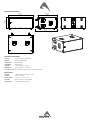
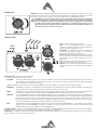
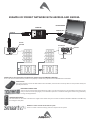
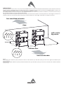
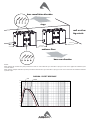
USER MANUAL
SW218A
ac ve subwoofer
KEY FEATURES
• Very High Output
• Compact size for a very good output-toweight ra o
• Digitally controlled Class D amplifier module with SMPS
• Manifolded Transmission Line configura on for very fast transient response
• 96KHz / 40 bit floa ng point CORE processing with PRONET remote control
INTRODUCTION
The SW218A subwoofer is designed to deliver high quality low frequency reproduc on where very high output is a key requirement, together
with well defined deep bass response and fast transient response. Its compact size and light weight
make it suitable for several different uses, ranging from touring applica ons to fixed installa ons and
high-level dance clubs.
The SW218A is a very high quality powered subwoofer system featuring some of the most advanced
technologies for low frequency reproduc on. Its unique and innova ve design is based on a configura on
that can be defined as Manifolded Transmission Line.
It uses manifolding of the front side of the cones to maximize the mutual coupling between the
two drivers, while loading the back of the cone with a large-size transmission line that has the
func on to create a transmission path from the back of the transducers to the front. This innova ve
configura on does not use any large resonant cavity to load the speaker in order to get the lower
octave and this reduces significantly pressure decay me inside the enclosure, with large advantages
in terms of defini on both at the lowest end and the upper bass. At the same me, it doesn’t use very
long transmission line paths as well. Its working principle is an hybrid combina on between a short
transmission line and an overdamped reflex load. Moreover, the maximiza on of the mutual coupling between the drivers increase the fastness
of the transient response while maximizing the overall energy efficiency as well.
The SW218A subwoofer system is equipped with two high power 18” (460mm) transducers capable of long excursion (up to 30mm peak-topeak), controlled by high s ffness Double Silicon Spider as centering suspension and by heavy duty surround. The motor structure features high
strength (BL²/Re) with op mized symmetry and excursion controlled by Inner Flux Demodula ng Ring. The robust copper 100mm (4”) voice coil is
wounded in two different layers both outside and inside the coil support, then doubling the coil surface exposed to air cooling and consequently
improving the long term thermal capacity of the loudspeaker. Cones are made of very high-s ffness glass fiber reinforced paper, featuring also
invisible water repellent treatment.
TECHNICAL SPECIFICATION
AcousƟcal
System type
Manifolded Transmission Line
Transducer
Two 18” (460 mm), 4” (100 mm) VC,
High s ffness, water repellent, glass fibre
reinforced cone
Flux Demodula ng Ring VC
Double Centering Spider Suspension
Amplifier Type
Class D with Variable Switching Frequency
and SMPS
Output Power
2000 W + 2000 W
Mains Voltage Range (Vac)
230 V~ ±15% or 115 V~ ±15% 50/60 Hz
PowerCon® (NAC3MPA + NAC3MPB)
1400 W (nominal) 3400 W (max)
Neutrik XLR-M / XLR-F
ETHERCON® (NE8FAV)
Frequency response (±3 dB)
Maximum Peak SPL @ 1m
Electrical
Input Impedance
Input Sensi vity
Signal Processing
20 kΩ balanced
+4 dBu / 1.25 V
CORE processing, 96kHz / 40bit floa ng
Mains Connector
Consump on*
IN / OUT Connectors
IN / OUT Network Connectors
Mechanical
Width
Height
Depth
Depth Including Wheels
point SHARC DSP, 24 bit AD/DA converters
Construc on
Direct access Controls
4 Presets: Standard, InfraSub, Cardioid, User. Paint
High resistance, water based paint
Network Termina on, GND Link
Wheels
4 heavy-load 100 mm ø
Remote Controls
PRONET control so ware
Transport
10 handles
Net Weight
101.7 Kg (223.7 lbs.)
36 Hz – 100 Hz (Processed)
141 dB
Network protocol
CANBUS
* Nominal consump on is measured with pink noise with a crest factor of 12
dB, this can be considered a standard music program.
1215 mm (47.87”)
590 mm (23.24”)
950 mm (37.43”)
1050 mm (41.37”)
15 mm, reinforced Phenolic Birch
MECHANICAL DRAWING
950 mm
37.43"
590 mm
23.24"
1215 mm
47.87"
1050 cm
41.37"
OPTIONAL ACCESSORIES
NAC3FCA
Neutrik Powercon® BLUE PLUG
NE8MCB
Neutrik Ethercon PLUG
NC3MXXBAG
Neutrik XLR-M
NC3FXXBAG
Neutrik XLR-F
USB2CAN
PRONET network converter
RAINCOV218
Rain protec on for connectors
see www.proel.com for detailed descrip on and other available accessories.
SPARE PARTS
AC103GS
100 mm Swivel castor without brake
AC115DN
Black steel handle
98NEOS18SW8
18’’ woofer - 4” VC - 8 ohm
NAC3MPA
Neutrik Powercon® BLUE SOCKET
91AMDSW218
Amplifier module assembly
POWER INPUT
MAINS IN - Powercon® NAC3FCA power input connector (blue). To switch the amplifier on, insert the
Powercon® connector and turn it clockwise into the ON posi on. To switch the amplifier off, pull back
the switch on the connector and turn it counter-clockwise into the POWER OFF posi on.
WARNING! In the case of product failure or fuse replacement, disconnect the unit completely
from the mains power. The power cable must only be connected to a socket corresponding
to the specificaƟons indicated on the amplifier unit. The power supply must be protected by
a suitably rated thermo-magneƟc breaker. Preferably use a suitable switch to power on the
whole audio system leaving the Powercon® always connected to each speaker, this simple trick
extend the life of the Powercon® connectors.
CONTROL PANEL
ON - This LED indicates power on status.
PROT - This red LED lights when the amplifier
module is in protect mode for an internal fault and,
consequently, the amplifier is muted.
SIGN LIMIT - This LED lights in green to indicate the
presence of the signal and lights in red when an
internal limiter reduces the input level.
INPUT - Audio signal input with locking XLR connector.
It has a fully electronically balanced circuitry including
AD conversion for the best S/N ratio and input
headroom.
LINK - A direct connec on from the input connector to
link other speakers with same audio signal.
GND LIFT - This switch li the ground of the balanced
audio inputs from the earth-ground of the amplifier
module.
PRESET BUTTON - This bu on has two func on:
1) Pressing it while powering on the unit:
ID ASSIGN
the internal DSP assigns a new ID to the unit for the PRONET remote control opera on. Each loudspeaker must have a unique
ID to be visible in the PRONET network. When you assign a new ID, all the other loudspeakers with the ID already assigned
must be ON and connected to the network.
2) Pressing it with the unit ON you can select the DSP PRESET. The selected PRESET is indicated by the corresponding LED:
STANDARD
This PRESET is suitable for any applica on where low frequency reinforcement is required. It features a 90Hz cut off frequency
and it can be used in almost any environment in combina on with any ver cal arrays.
INFRA
This PRESET can be used when a deeper bass response is required (Note that when this preset is used the sound pressure level
of the system is slightly reduced). NOTE: INFRA and STANDARD PRESET must NOT be used together in close units.
CARDIOID
This special PRESET, combined with the STANDARD PRESET, gives the advantage to reduce the low frequencies at the back of
an array of three subs, in order to obtain a more comfortable level for the performers on the stage without losing level for the
the audience in front of the array. The cardioid configura on is also useful in situa on where you want to reduce the bass
frequency feedback due to many microphones on stage, for example for acous c and jazz ensemble, classic orchestra, musicals.
Further in this manual you can find some example how to set up a cardioid array.
USER
This LED lights when the USER PRESET is loaded. This preset corresponds to USER MEMORY no. 1 of the DSP and, as a factory
se ng, it’s the same to STANDARD. If you want to modify it, you have to connect the unit to a PC, edit the parameters with
PRONET so ware and save the PRESET into USER MEMORY no. 1.
NETWORK IN/OUT - These are a standard RJ45 CAT5 connectors (with op onal NEUTRIK NE8MC RJ45 cable connector carrier), used for PRONET
network transmission of remote control data over long distance or mul ple unit applica ons.
TERMINATE - In a PRONET network the last loudspeaker device must be terminated (with an inner load resistance) especially in a long run cabling:
press this switch if you want to terminate the unit.
POWER AMPLIFIERS
The SW218A is powered by DA SERIES digital power modules, a new genera on of CLASS D power amplifier with digitally-controlled SMPS.
The innova ve technology used for these amplifiers (including also the use of a variable switching frequency) offers performances at the top of
the range, such as a superior sound defini on at any audio frequency, very high dynamics also for low level signals and very low distor on even at
the maximum power The superior sound quality can be compared with top-of-the-range AB-class analog systems, while the DA modules feature a
higher dynamics, very compact size and light weight and efficiency above 90%. The two DA modules employed for powering the SW218A deliver
in an ultra-compact package a maximum power of 4000W.
SIGNAL PROCESSING
The system processing is based on the CORE DSP pla orm, which has been designed by the PROEL R&D Laboratories using one of the most
advanced SHARC DSP for audio applica on. It features 40bit, 96kHz floa ng point resolu on and high quality 24bit AD/DA converters, for a perfect
signal integrity, a dynamic range in excess of 110dB and a superior sonic performance. Thanks to its massive processing power, the CORE pla orm
is capable of providing the most sophis cated algorithms for speaker processing, together with remote control and networking capability.
The PRONET control so ware, working on a solid and reliable CANBUS based network protocol, provides an intui ve interface for the remote
control of the whole system, with the possibility of eqing, delaying, increasing the protec ons and monitoring the status of the amplifier.
PRONET
PRONET so ware has been designed by Proel’s Research & Development Department to easily control a single unit or a network of devices, like
ac ve loudspeakers or speaker processors, equipped with the C-AUDIO CORE digital processing pla orm.
PRONET has been developed in collabora on with sound engineers and sound designers, in order to offer an “easy-to-use” tool to setup and
manage your audio system. With PRONET you can visualize signal levels, monitor internal status and edit all the parameters of each connected
device.
Download the PRONET app from the PROEL website at h p://www.proel.com clicking on support / download sec on.
The SW218A loudspeaker devices can be connected using the network connec on, in this case the PROEL USB2CAN converter op onal accessory is
needed. The first me you connect a device with the USB2CAN converter, Windows O.S. will ask you to install the driver files, which you can find in
the Driver folder within the Pronet applica on folder (by default is C:\Program Files\Proel\Pronet\Driver, or if you changed it <your path>\Driver).
Please refer also to “Installa on” and “Drivers” paragraphs in the Pronet documenta on.
The PRONET NETWORK is based on a robust, reliable and fast communica on protocol called CANBUS. The devices in a PRONET NETWORK are
connected together with a “linear bus topology”. The USB2CAN converter must be connected to the network input of the first device, the network
output of the first device is connected to the input of the second and so on. For the network connec ons simple RJ45 cat.5 or cat.6 ethernet
cables can be used (please don’t confuse a ethernet network with a PRONET network these are completely different and must be fully separated
also both use the same kind of cable).
The beginning and the end of a PRONET NETWORK must be terminated. One side is terminated by the USB2CAN converter, the other side must
be terminated pressing the TERMINATE switch on the last device. All devices between these two points must have the TERMINATE switch li ed.
Assign the ID number
To work properly in a PRONET network each connected device must have a unique iden fier number, called ID. By default the USB2CAN PC
controller has ID=0 and there can be only one PC controller. Every other device connected must have its own unique ID equal or greater than 1:
in the network cannot exist two devices with the same ID.
An ID number is assigned automa cally to each devices when they are turned on for the first me connected to a network.
In order to correctly assign a new available ID to each device for working properly in a Pronet network, follow these instruc ons:
1. Switch off all the devices.
2. Connect them correctly to the network cables.
3. “TERMINATE” the latest device in the network connec on.
4. Switch on the first device keep pressed “PRESET” bu on on the control panel.
5. Leaving the previous device switched on, repeat the previous opera on on the next device, un l the latest device is turned on.
The “Assign ID” procedure for a device makes the internal network controller to perform two opera ons: reset the current ID; search the first free
ID in the network, star ng from ID=1. If no other devices are connected (and powered on), the controller assume ID=1, that is the first free ID,
otherwise it searches the next one le free.
These opera ons ensure that every device has it’s own unique ID, if you need to add a new device to the network you simply repeat the opera on
of step 4. Every device maintains its ID also when it is turned-off, because the iden fier is stored in the internal memory and it is cleared only by
another “Assign ID” step, as explained above. This means that if your network is made always of the same devices the assigning ID procedure must
be executed only the first me the system is turned on.
For more detailed instrucƟon about PRONET see the PRONET USER’S MANUAL included with the soŌware.
EXAMPLE OF PRONET NETWORK WITH AX2010A AND SW218A
PC NOTEBOOK
USB2CAN
STATUS
USB2CAN
USB 2.0 port
CONVERTER
CODE:
USB2CAN
S/N:
00001
RATINGS: 5V --- 200mA
RoHS COMPLIANT
MADE IN ITALY
network
do not
pressed
last device
pressed
AX2010A
network
Useful tools to set up properly a verƟcal array system using the SW218A subwoofer
This is a list of tools that can be very useful to set properly a ver cal array system with the SW218A ac ve subwoofers.
CABLE TESTER
It is a good prac ce to check all cables before each installa on, because even one faulty cable can compromise heavily the
system performance.
INCLINOMETER WITH LEVER
This tool can be used to verify the ver cal array angle. It can be used at the top or at the bo om of the array In this
case you have to sum all splay angles, so the maximum precision is needed for aiming the ver cal array, par cularly
for long throw applica ons.
LASER DISTANCE METER
This instrument can be useful to measure the height of the ver cal array and to know the distance between FOH-Subs and FOH-Array
for se ng the delay me.
SMAART or similar acousƟc measurement system
These are useful to measure delays, phase and response of the system.
CARDIOID PRESET
The cardioid preset must be used in a sub array of three SW218A. Two box must be oriented towards the audience and one must be turned in the
opposite direc on (typically the box in the centre of the array). The bo om and the top boxes must have the STANDARD PRESET, the box in the
middle must have the CARDIOID PRESET. The audio signal sent to all boxes is the same.
The CARDIOID PRESET has the same response of the STANDARD PRESET, but to obtain the maximum cancella on on the back side of the array it
has the phase inverted and a proper level and delay se ng.
The figure below shows two typical displacement of the array. The first with all the boxes in horizontal posi on for a total height of 1770 mm and
a width of 1215 mm. The second one with all the boxes in ver cal posi on for a total height of 1215 mm and a width of 1770 mm.
bass cancellaƟon direcƟon
stage
wall or other
big ostacle
80 cm min.
2.7 Ō min.
80 cm min.
2.7 Ō min.
80 cm min.
2.7 Ō min.
audience floor
bass sum direcƟon
NOTES:
When placing the cardioid array keep a distance to walls or other obstacles of at least 80 cm (2.6 ) in order not to affect the radia on of the
reversed cabinet.
When placing mul ple cardioid arrays keep a distance between them of at least 80 cm (2.6 ) in order not to maximize the combined radia on
of whole arrays.
SW218A - PRESET RESPONSE
INFRA
STANDARD
+15
+10
+5
0
-5
-10
-15
-20
-25
-30
-35
20
50
100
200
500
1K
2K
5K
10K
20K
Hz
LIMITED WARRANTY
Proel warrants all materials, workmanship and proper opera on of this product for a period of two years from the original date of purchase. If any defects are found
in the materials or workmanship or if the product fails to func on properly during the applicable warranty period, the owner should inform about these defects the
dealer or the distributor, providing receipt or invoice of date of purchase and defect detailed descrip on. This warranty does not extend to damage resul ng from
improper installa on, misuse, neglect or abuse. Proel S.p.A. will verify damage on returned units, and when the unit has been properly used and warranty is s ll
valid, then the unit will be replaced or repaired. Proel S.p.A. is not responsible for any “direct damage” or “indirect damage” caused by product defec veness.
• This unit package has been submi ed to ISTA 1A integrity tests. We suggest you control the unit condi ons immediately a er unpacking it.
• If any damage is found, immediately advise the dealer. Keep all unit packaging parts to allow inspec on.
• Proel is not responsible for any damage that occurs during shipment.
• Products are sold “delivered ex warehouse” and shipment is at charge and risk of the buyer.
• Possible damages to unit should be immediately no fied to forwarder. Each complaint for package tampered with should be done within eight days from product
receipt.
SAFETY INSTRUCTIONS
– To reduce the risk, close supervision is necessary when the product is used near children.
– Protect the apparatus from atmospheric agents and keep it away from water, rain and high humidity places.
– This product should be site away from heat sources such as radiators, lamps and any other device that generate heat.
– This product should be located so that its loca on or posi on does not interfere with its proper ven la on and hea ng dissipa on.
– Care should be taken so that objects and liquids do not go inside the product.
– The product should be connected to a power supply mains line only of the type described on the opera ng instruc ons or as marked on the product. Connect the
apparatus to a power supply using only power cord included making always sure it is in good condi ons.
– WARNING: The mains plug is used as disconnect device, the disconnect device shall remain readily operable.
– Do not cancel the safety feature assured by means of a polarized line plug (one blade wider than the other) or with a earth connec on.
– Make sure that power supply mains line has a proper earth connec on.
– Power supply cord should be unplugged from the outlet during strong thunderstorm or when le unused for a long period of me.
CE CONFORMITY
Proel products comply with direc ve 2004/108/EC (EMC), as stated in EN 55103-1 and EN 55103-2 standards and with direc ve 2006/95/CE (LVD), as stated in EN
60065 standard.
PROEL S.p.A. (World Headquarter) - Via alla Ruenia 37/43 - 64027 Sant’Omero (Te) - ITALY
Tel: +39 0861 81241 Fax: +39 0861 887862 www.proel.com


![[U4.44.22] Opérateur MODI_OBSTACLE](http://vs1.manualzilla.com/store/data/006356813_1-2c70d2f06f0b16eeac21e0f75900d7cc-150x150.png)