1
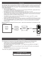
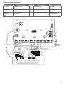
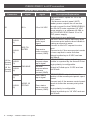
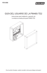
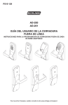
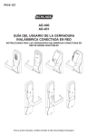
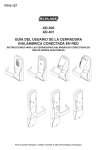
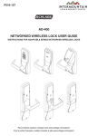
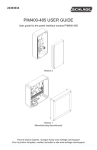
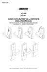
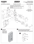
*P516-097*
P516-097
PIB300 and PIB301 User Guide
Installation and operation instructions for Panel Interface Board
Para el idioma español, navegue hacia www.schlage.com/support
Pour la portion française, veuillez consulter le site www.schlage.com/support
Contents
Overview............................................................................................................................3
Getting started...................................................................................................................3
Handheld device (HHD).....................................................................................................4
PIB300/PIB301 installation................................................................................................4
Location.........................................................................................................................4
Wiring to the lock...........................................................................................................4
Connect the PIB300/PIB301 to the access control panel (ACP)................................... 4
Cable/wire specifications...............................................................................................5
Typical wiring to the access control panel......................................................................5
PIB300/PIB301 to ACP connection...................................................................................6
Complete the installation...................................................................................................8
Access point ACP connections to a RS-485 device address ........................................8
Reset to factory defaults....................................................................................................8
FCC statements.................................................................................................................8
This product is compliant of UL 294 and ULC S319 standard. This product’s compliance
would be invalidated through the use of any add-on, expansion, memory or other module
that has not yet been evaluated for compatibility for use with this UL Listed product, in
accordance with the requirements of the Standards UL 294 and ULC S319. This product has
been evaluated for ULC-S319 Class I.
2 • Schlage • PIB300 / PIB301 user guide
Overview
The Schlage Panel Interface Board (PIB300 or PIB301) provides a means of connecting RS485 based access point devices to a system requiring wiegand or clock and data protocol
(rather than direct RS-485 connection). This manual describes the installation and operation
of the PIB300/PIB301.
• Open architecture platform
• The Schlage PIB301 provides a means of connecting the FIPS-201 certified AD-301 to
an access control system via Wiegand protocol
• Provides two-way communication with locks via a RS-485 connection
• The PIB300 may connect up to two Schlage AD-300 locks or up to two RS-485 based
legacy locks communicating with the RSI or VIP protocol, may connect to an Access
Control Panel (ACP) or reader interface board
• The PIB301 may connect up to two Schlage AD-301 locks to an ACP or reader
interface board via wiegand protocol
• Legacy and AD-300 locks may not both be present on the PIB300’s RS-485 connection
• The trouble signal output will change state when the Anti-Tamper Switch (ATS) signals
that the PIB300/PIB301 enclosure lid is open, or if an access point device indicates
trouble status.
Before installing a Schlage AD-Series system, read all documentation for all products in the
installation.
Access
Control
Panel
Wiegand or
Clock & Data
for PIB300
Wiegand only
for PIB301
PIB300
PIB301
RS485
AD-300
AD-301
Getting started
The following is an overview of the steps required for setting up the PIB300/PIB301.
• Install the lock. See the installation guide that came with the lock, or visit
www.schlage.com/support for more information.
• Use proper wiring to the PIB300/PIB301. See Cable/wire specifications on page 5
for more information.
• Disconnect power to the lock and Access Control Panel (ACP) while connecting the
PIB300/PIB301.
• Familiarize yourself with the information in this user guide.
Save this user guide for future reference.
Customer Service
1-877-671-7011 www.allegion.com/us
3
Handheld device (HHD)
The Handheld Device (HHD) is used for programming and setup only.
The HHD is used to configure this device’s links and outputs. For information about the HHD,
see the SUS user guide.
PIB300/PIB301 installation
Location
• The PIB300/PIB301 should be located close to the access control panel (wiring distance
may be up to 500 feet (152 meters)).
Wiring to the lock
• Power wire for locks must be appropriately sized for the distance and voltage.
• Communication wire should be suitable for use on RS-485 type networks.
• The maximum length of the RS-485 wiring from the PIB300/PIB301 to lock 2 is 4000
feet (1219 meters).
• Wiring of locks requires one connector via the RS-485 connector (J5).
• Connections from lock to lock should be daisy-chained (see diagram below).
• The power supply is located at or near the PIB300/PIB301 for short wire runs, or local to
locks if located far from the panel.
PIB300
PIB301
RS485
Lock 1
ACP
Lock 2
Daisy Chain
Connect the PIB300/PIB301 to the access control panel (ACP)
CAUTION: Disconnect the ACP power and batteries while wiring the PIB300 /PIB301 to
the panel.
WARNING: Because every access control panel is different, always check the panel’s
instruction manual for appropriate interface wiring.
• For compliance with UL 294, product must be used with a UL 294 Listed access control
panel or unit. For compliance with ULC S319, product must be used with a ULC S319
Listed access control panel or unit.
• Must be connected to external power using a UL294 listed power supply for UL
installations, and a power supply that complies with CAN/ULC-S318 or CAN/ULC-S319
for cUL installations. The power supply must be capable of sourcing 250mA @ 12 or 24
VDC (example: Schlage PS902, PS904, PS906). Refer to Typical wiring to the access
control panel on page 5 for how to connect DC power to the PIB300/PIB301.
• Use shielded cables for the signal wiring between the PIB300/PIB301 and the ACP. For
maximum wire lengths and cable specifications, sSee Cable/wire specifications on page
5 for more information..
4 • Schlage • PIB300 / PIB301 user guide
Cable/wire specifications
Application
DC power
input
RS-485
PIB300/
PIB301 to
ACP
Part number
Belden 8760 or
equivalent
Belden 9841, 9842 or
equivalent
Alpha 1298C or
equivalent
AWG
Description
18
2 conductor
24
22
Max run length
1000 feet
(305 meters)
4000 feet
(1219 meters)
500 feet
(152 meters)
2 or 4 conductor
shielded
8 conductor shielded
Typical wiring to the access control panel
J2
J5
GND
TB+
RB+
LINK1
J8
J7
LINK2
J10
TA−
RA−
J11
RS485 connection
to daisy-chained
access point 1
and
access point 2
Do not connect cable
shields at PIB300
Run shielded cables
through grounded conduit.
Req to Enter
Req to Enter Gnd
Trouble
Trouble Gnd
Status
Status Gnd
Req to Exit
Req to Exit Gnd
Strike Input
Strike Input Gnd
D1/CLK
D0/DATA
Gnd
Access Control Panel
Notes: Only AP1 is shown connected. AP2 should be connected the same way.
Unsupervised, ground switched inputs to panel shown. Some Access Control
Panels require supervised inputs and/or “dry contact” isolated inputs.
The optional Schlage RLBD is available for these applications.
5
PIB300/PIB301 to ACP connection
Connector
J2
ACCESS CONTROL PANEL CONNECTION
PIB300/301 Access panel
signal
signal
Description/Explanation
PIB300/PIB301 inputs for 12 or 24
VDC power.
12V+
Request to
enter input
signal
J10/J11
(1)
J10/J11
(2)
J10 for J10/J11
Access (3)
Point A
J11 for
J10/J11
Access
(4)
Point B
12 or 24 VDC
REQ TO
ENTER
TROUBLE
J10/J11
(5)
DOOR 1/2
J10/J11 STATUS
(6)
6 • Schlage • PIB300 / PIB301 user guide
If the access control panel (ACP)
reader power outputs do not source
enough current for the PIB300/PIB301,
use the ACP main regulated 12 VDC
power supply or a separate UL 294 or
ULC S318/ULC S319 listed 12 or 24
VDC power supply.
Power input is non polarized.
PIB300/PIB301 output indicating when
the access point exterior door handle is
making a request to enter.
Connect to the ACP request to enter
input.
Request to
enter common Connect only if the access point needs
contact (GND) to have request to enter function.
Output is pulled-up to 5 VDC and can
sink 50mA.
General
PIB300/PIB301 output indicating
purpose alarm trouble is reported by the Access Point.
input signal
Logic polarity is configurable.
General
Output is Pulled-up to 5 VDC and can
purpose alarm
sink 50mA.
common
contact (GND)
PIB300/PIB301 output indicates the
Door status
position of the access point portal, open/
input signal
closed.
Connect only if the access control panel
needs to know the access point portal
state.
Door status
input common
contact (GND) Logic polarity is configurable.
Output is pulled-up to 3.6 VDC and can
sink 50mA.
Connector
J10 for
Access
Point A
J10/J11
(7)
ACCESS CONTROL PANEL CONNECTION
PIB300/301 Access panel
signal
signal
Description/Explanation
PIB300/PIB301 output indicating when
Request to exit the access point interior door handle is
input
making a request to exit.
REQ TO EXIT
J11 for J10/J11
Access (8)
Point B
J11 (9)
+5V
J8/J7
(1)
STRIKE
INPUT
J8/J7
(2)
J8 for
Access
Point A J8/J7
(3)
J7 for
Access
Point B
J8/J7
(4)
D1/CLK
Connect to the access control panel
request to exit input.
Request to
Connect only if the access point needs
exit common
to have request to exit function.
contact (GND)
Output is pulled-up to 5 VDC and can
sink 50mA.
RESERVED 5 VDC power supply pin
5 VDC
for the RLBD, dry contact relay board.
Strike input monitors the access panel
Normally open strike relay.
strike relay
Connect the strike signal to the normally
contact
open or normally closed terminal of the
strike relay. The active signal state of
the PIB300/PIB301 is programmable
with the HHD.
Common strike
Connect the ground signal to the
relay contact
common terminal of the strike relay.
Clock or
data 1 output
Connect only if the access point needs
to be unlocked (door) or raised (gate).
PIB300/PIB301 outputs used to present
card data to the ACP.
For an access point with a magnetic
reader, will present clock and data
signals to the access control panel.
DATA
Data or
data 0 input
For an access point with a wiegand or
proximity reader, will present Data1 and
Data0 signals to the ACP.
If initial hookup fails to operate, switch
wires at these terminals.
J8/J7
(5)
GND
Signal ground
Output is pulled-up to 3.6 VDC and can
sink 50mA.
Common signal ground for the EXIT
REQ, DOOR STAT, TROUBLE, DATA/
D0 and CLK/D1 signals.
7
Complete the installation
After all required connections have been made, connect the power and ACP standby
batteries to the panel.
Access point ACP connections to a RS-485 device address
The PIB300/PIB301 access point to ACP connections are each associated with a RS-485
device address. This association is set using the Schlage utility software (SUS). Please see
the SUS user manual for further information.
The PIB300/PIB301 defaults to access point 1 connections associated with RS-485 device
address 0x00 and access point 2 connections associated with RS-485 device address 0x01.
Reset to factory defaults
All configuration information will be deleted and the PIB300/PIB301 will be reset to
factory defaults!
1. Remove the main cover.
2. Press and hold both link buttons for over 3 seconds.
3. Release both link buttons. The PIB300/PIB301 will blink the red lights beside each link
button while configuration reset takes place.
4. The two green lights beside the link buttons will blink 3 times when the reset is complete.
5. Replace the main cover.
FCC statements
Allegion agency statements
Compliance statement (Part 15.19)
This device complies with Part 15 of the FCC Rules.
Operation is subject to the following two conditions:
1. This device may not cause harmful interference, and
2. This device must accept any interference received, including interference that may cause undesired operation.
Warning (Part 15.21)
Changes or modifications not expressly approved by the party responsible for compliance could void the user’s
authority to operate the equipment.
FCC interference statement (Part 15.105 (b))
This equipment has been tested and found to comply with the limits for a Class B digital device, pursuant to Part
15 of the FCC Rules. These limits are designed to provide reasonable protection against harmful interference in a
residential installation. This equipment generates uses and can radiate radio frequency energy and, if not installed
and used in accordance with the instructions, may cause harmful interference to radio communications. However,
there is no guarantee that interference will not occur in a particular installation. If this equipment does cause
harmful interference to radio or television reception, which can be determined by turning the equipment off and on,
the user is encouraged to try to correct the interference by one of the following measures:
• Reorient or relocate the receiving antenna.
• Increase the separation between the equipment and receiver.
• Connect the equipment into an outlet on a circuit different from that to which the receiver is connected.
• Consult the dealer or an experienced radio/TV technician for help.
RF exposure statement
To comply with FCC/IC RF exposure requirements for mobile transmitting devices, this transmitter should only
be used or installed at locations where there is at least 20 cm separation distance between the antenna and all
persons.
Section 7.1.5 of RSS-GEN
Operation is subject to the following two conditions:
© Allegion 2014
1. This device may not cause interference, and
Printed in U.S.A.
2. This device must accept any interference,
P516-097 Rev. 03/14-f
including interference that may cause
undesired operation of the device.
5.500”
11.000”
FRONT
FRONT
8.500”
8.500”
BEGINNING SHEET
FOLDED SHEET
Additional Notes:
1. Booklet format, center stitched
Revision History
A
B
C
D
E
F
010968
013037
014686
028472
30052
48533
Material
White Paper
Notes
1. printed two sides
2. printed black
3. tolerance: ± .13
4. see sheet 2 for artwork
5. printed in country may vary
6. drawings not to scale
Revision Description:
f > SH2 Artwork revision
Edited By
Approved By
EC Number
Release Date
P. Bockelman
M. Roberts
48533
03-28-14
Title
User Guide, AD-Series PIB300
Creation Date
12-21-2009
Created By
P. Bockelman
Software: InDesign CS6
Number
Revision
P516-097
Activity
3899 Hancock Expwy
Security, CO 80911
f
© Allegion 2014