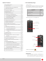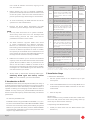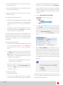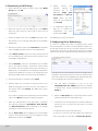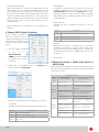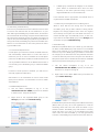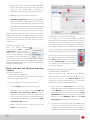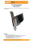
1
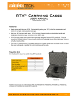
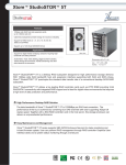
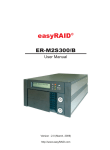
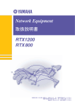
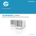
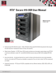
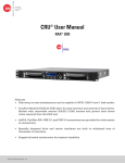
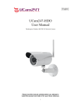
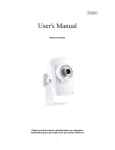
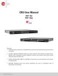
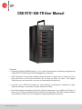
CRU RTX® 800-TR User Manual
Features
• Supports JBOD and RAID levels 0, 1, 4, 5, 6, and 10 in hardware, with easy configuration
using ATTO Technology’s RAID management software.
• C
RU TrayFree™ bays make adding drives effortless: simply open a drive bay door,
slide the drive in, and close the door. No screws, no trays, no tools. The rugged
TrayFree bays are rated for over tens of thousands of insertions.
• P
rovides up to 32TB of storage for video editing, visualization, simulation, highcapacity storage, or backups of large amounts of data.
• D
ual Thunderbolt interfaces allow the fastest connection to your Mac or PC host, at
rates up to 10 Gbps in both directions and at the same time. This kind of performance
can transfer or back up 1TB of content in approximately 20 minutes.
A9-800-0003 Revision 1.0
Table of Contents
1. Pre-Installation Steps
1.1 Box Contents
1.2 Identifying Parts of your RTX800-TR
1.3 Warnings and Notices
1. Pre-Installation Steps
2
2
2
2
2. Introduction to RAID
3
2.1 Summary of RAID Levels
3. Installation Steps
3.1 Hard Drive Installation
3.2 Operating Your RTX Enclosure
3.2.1 Installing Thunderbolt Drivers
3.2.2 Install ATTO ConfigTool
3.2.3 Configuring RAID
4. Customizing a RAID Setup
5. Configuring Drive Redundancy
3
3
3
3
4
4
4
5
5
5.1 Create a Hot Spare Pool
5
5.2 Enable Auto-Rebuild
6
6. Change RAID Group Properties
6
7. Recovering From A Failed Hard Drive or RAID
Group
6
7.1 Rebuilding the RAID Group
7
7.1.2 Manual Replacement
7
7.1.3 Recovery from Replacement of a Wrong
Drive
7
7.2 Data Recovery
7
8. RAID Notifications
8
8.1 Configuring Visual, Audible, and System
Log Alerts
8
8.2 Configuring E-Mail Notifications
8
8.3 Retrieving System Logs
9
9.1 Usage with Mac OS X
Accessories
Quantity
RTX800-TR Enclosure
1
Thunderbolt Cable
1
Power Cord
1
Quick Start Guide
1
1.2 Identifying Parts of your RTX800-TR
Drive Power
and Activity LEDs
TrayFree Bay
7
7.1.1 Automatic Replacement
9. Usage with Mac and Windows Operating
Systems
1.1 Box Contents
The following list contains the items that are included
in the complete configuration for this device. Please
contact CRU if any items are missing or damaged:
9
Ejection Handle
Thunderbolt
Ports
Cooling Fans
9
9.1.1 Formatting the RAID Group
9
9.1.2 Mounting and Unmounting Volumes
9
9.2 Usage with Windows Operating Systems
9
9.2.1 Formatting the RAID Group
9
9.2.2 Mounting and Unmounting Volumes
10
10. RAID is Not A Backup
10
11. Technical Specifications
11
Power
Switch
Power Port
1.3 Warnings and Notices
Please read the following before beginning installation.
General Care
• Proper grounding is strongly recommended to
prevent electrical damage to the enclosure or
other connected devices, including the computer
Page 2
CRU Mark
10.25.12
PMS 711
2 cyan
host. Avoid all dramatic movement, tapping on the
unit, and vibration.
•
•
•
Before starting any type of hardware installation,
please ensure that all power switches have been turned
off and all power cords have been disconnected to
prevent personal injury and damage to the hardware.
To avoid overheating, the RTX enclosure should be
operated in a well-ventilated area.
Remove the drives before transporting the RTX
enclosure to prevent damage to the drive interfaces.
RAID
• Use only hard drives that are in perfect condition.
Avoid using drives that have ever developed bad
sectors during previous use. This could lead to
possible device failure or loss of data.
•
•
•
The RTX enclosure supports SATA hard drives
of various specifications and different capacities.
However, we recommend using drives of the same
brand and type across all bays for optimal performance.
If drives of different capacities are used in a RAID,
the capacity of the smallest drive will determine how
much of each drive is used. The additional capacity on
the larger drives will not be used by the RAID.
RAID level 0 will allow you to use the full combined
capacity of the drives and offers the best data transfer
speeds. However, RAID 0 offers no protection for the
data. If one drive fails in a RAID 0, the data on all of
the drives is irretrievably lost. Before creating a RAID,
investigate the various RAID types and choose the
one that is best for your needs.
Always back up data before switching RAID types.
Switching RAID types will destroy current
data. You must reformat your drives afterwards.
2 Introduction to RAID
A RAID (Redundant Array of Independent Disks) is an array of
multiple hard drives that are combined in a way that provides
faster performance and/or data safety. Your RTX enclosure is
capable of creating and managing several different varieties
of RAID. You may choose your preferred RAID level based on
factors such as disk capacity, desired data safety, and desired
performance.
2.1 Summary of RAID Levels
The RTX enclosure supports RAID Levels JBOD, 0, 1, 4, 5, 6,
10, and a custom RAID mode called ATTO DVRAID™. RAID
Level 5 is most commonly used by those seeking an optimal
balance of speed and data safety, however ATTO DVRAID
is optimized for applications such as video production that
require a high data transfer rate.
Page 3
RAID
Level
Description
Required
No. of
Drives*
Fault
Tolerance
JBOD
Known as “Just a Bunch Of Disks”.
This is not a type of RAID as each
disk is created with its own independent volume. There is no data
protection.
1
No data
protection
0
Also known as striping. Data distributed across all drives in the array. There is no data protection.
2 or 4
No data
protection
1
Also known as mirroring. All data
replicated on two separate disks.
Due to the 100% duplication, only
half the total disk capacity is available for data storage.
2
1 drive
4
Parity information is dedicated to a
single disk while data information
is subdivided across the remaining
disks. Can withstand the failure of
one drive.
3
1 drive
5
Data and parity information is subdivided and distributed across all
disks. Can withstand the failure of
one drive. The total capacity of all
but one of the drives is available for
data storage.
3
1 drive
6
Extends RAID 5 by adding an additional block of parity information
that is subdivided across all disks,
and provides protection against
data loss during a RAID rebuild.
4
2 drives
10
Also known as Block-Interleaved
Parity. Data is striped across two
separate disks and mirrored to another disk pair.
4
1 drive**
ATTO
DVRAID
Parity redundancy optimized for
high data transfer rates.
6
1 drive
* The RAID level becomes available as a menu option when exactly these numbers of hard drives
are installed inside of the RTX enclosure.
**If both drives in either the RAID 0 or RAID 1 set fail, then the entire RAID will fail. If
only one drive in each of the RAID 0 and RAID 1 sets fail, then the RAID is preserved.
3 Installation Steps
3.1 Hard Drive Installation
a. Pull the ejection handle on the TrayFree bay to open
the bay door.
b. I nsert a bare SATA hard drive into the bay. Make sure it
is label-side up with the SATA connection on the drive
inserted first.
c. Shut the bay door.
Sticker Card
Use the stickers on the provided sticker card to label each
drive. This will prevent the drives from getting mixed up
when they are removed from the bays.
3.2 Operating Your RTX Enclosure
a. Install your hard drives into the RTX enclosure (see
Section 1.1).
CRU Mark
10.25.12
PMS 711
2 cyan
b. C
onnect the RTX enclosure to a power outlet with the
included power cord.
plugged into. If the RTX enclosure is plugged into the
computer you are currently using, select localhost.
c. C
onnect the RTX enclosure to your computer using the
included Thunderbolt cable.
c. A login window will pop up. Provide the username
and password for the computer the RTX is connected
to and press OK. The device listing for that computer
will appear.
d. F
lip the power switch on the rear of the unit to turn on
the RTX enclosure.
d. Click on ThunderStream SC 3808E.
3.2.1 Installing Thunderbolt Drivers
a. D
ownload the appropriate Thunderstream SC 3808E
driver for your operating system from the RTX800-TR
product page: www.cru-inc.com/products/RTX800TR.php.
b. On Windows machines, open the ZIP file and run the
included .EXE file. Press the Unzip button and then
follow the prompts to install the driver.
On Mac machines, the folder will automatically unzip.
Open the folder and double click on the .dmg file. A new
folder will open. Double click on the .pkg file and follow
the prompts to install the driver. A computer restart will
be required.
3.2.2 Install ATTO ConfigTool
a. Download the version of ATTO ConfigTool appropriate
for your operating system from the RTX800-TR
product page: www.cru-inc.com/products/RTX800TR.php.
b. On Windows machines, open the .exe file and click
the Unzip button. The setup files will unzip. Press
OK. Navigate to the folder you unzipped it to (the
default path is “C:\ATTO\ConfigTool”) and open the
ConfigTool_411.exe file there.
e. A new set of tabs will appear in the right panel. Click
on the RAID tab. If this is the first time setting up
a RAID on these hard drives, the RAID wizard will
automatically open. If it does not start automatically,
select the RAID Management menu item at the
top of the screen and select New Group… from the
menu.
f.
Select Setup DVRAID to automatically set up a
RAID. To customize your RAID setup with a standard
RAID mode, see Section 4 . DVRAID provides parity
redundancy for your data and is optimized for the
high data transfer rates that are required in digital
video editing. The wizard will automatically set
up DVRAID using all the storage inside of the RTX
enclosure.
For Mac, open the ConfigTool_4xx file inside of
the .dmg file you downloaded.
c. Follow the onscreen instructions. On the “Choose
Install Set” screen, select Full Installation and
then click the Next button. Continue to follow the
onscreen instructions.
3.2.3 Configuring RAID
a. Open ATTO ConfigTool.
b. From the Device Listing panel on the left, expand
the list and select the computer that your RTX is
Page 4
Your RTX enclosure is almost ready to use! Now that
you have created a RAID, the volume(s) will need to be
formatted before being used.
CRU Mark
10.25.12
PMS 711
2 cyan
4 Customizing a RAID Setup
a. After following the steps in Section 3.2.3, select HDD
Group and click OK.
k. Finally,
choose
your
partition
options
by
choosing one of the
following: single, split
by capacity, or split by
count. When you have
made all your selections,
click Finish.
l.
b. Enter the name for the new RAID group in the Name
field. The name must be unique and no more than 14
characters.
c. Select the RAID level from the Level drop-down box.
See Section 2.1 for a list and description of the available
RAID levels.
d. Select the interleave value under Interleave. The default
value is 128KB and will be fine for most applications.
e. Under Mirror Count, choose how many mirrors that will
be in the RAID group. This option will be greyed out for
most RAID configurations.
f.
Under Initialize, select the initialization for the RAID
group. The default setting is Advanced, which erases
and verifies the drive media. During this procedure the
RAID group is unavailable for use. Express initialization
performs the RAID group setup in the background and
allows the RAID group to be used during initialization.
A confirmation dialog box
asks you to confirm the
configuration you have
chosen. Select Yes.
The RAID group setup is complete.
5 Configuring Drive Redundancy
If a drive in a RAID group fails, the RAID group’s status
becomes degraded. In order to maintain RAID integrity, you
should plan ahead and use one of these methods to ensure
that should a drive fail, your data will not remain at increased
risk for long. Use the method below that best fits your needs.
5.1 Create a Hot Spare Pool
g. Once the settings are complete, select Next.
A faulted drive is automatically replaced if a suitable disk is
available in the Hot Spare Pool. You set up a Hot Spare Pool
with drives reserved until a RAID group member fails; they
are not available when creating a RAID group.
h. Add the disks you would like to include as part of the
RAID by dragging the drives from the top window to
the bottom. Then click Finish. The RAID group setup
is complete.
a. Use the ATTO ConfigTool to log in to the
ThunderStream SC 3808E properties as detailed
in Section 3.2.3 , Steps A through E. and click on the
RAID tab.
If you want to change other parameters from the default
values, click Next and select the desired property.
b. Select the Hot Spare tab in the bottom panel to show
existing members of the Hot Spare Pool.
i.
After you selected Next in the step above, customize
the following properties: SpeedRead, Auto-Rebuild,
and Rebuild Priority. Refer to Section 6 for specific
information on each of these options.
c. To add drives to the Hot Spare Pool, select unallocated
drives from the top panel and drag them to the Hot
Spare Pool.
j.
Set the Sector Size that the RAID group virtual disk(s)
will use. This parameter can only be configured during
RAID group creation. Click Next.
Page 5
5.1.1 Remove Drives from Hot Spare Pool
To remove a drive from the Hot Spare Pool, select the
drive, right click on it and click on Delete Hot Spares.
CRU Mark
10.25.12
PMS 711
2 cyan
5.2 Enable Auto-Rebuild
When Auto-Rebuild is enabled, the RTX enclosure will
automatically use any suitable unallocated drive it finds
as a replacement for a faulted drive. Suitable drives must
be large enough to replace the degraded drive and cannot
contain any RAID group information. If a Hot Spare Pool
exists, the RTX enclosure will default to using an available
Hot Spare drive from the pool before searching for an
unallocated drive.
Refer to Section 6 for instructions on how to enable AutoRebuild.
6 Change RAID Group Properties
Some of these properties can
only be specified during the
creation of the RAID group while
others may be changed at any
time during the life of the RAID
group.
Auto-Rebuild
Controls the replacement of a faulted drive with any
available unallocated drive. When you click on the
Auto-Rebuild check box and the Accept button, AutoRebuild is enabled. If a drive becomes faulted, the SAS/
SATA RAID storage controller replaces the drive with an
unallocated drive.
Rebuild Priority
Specifies the ratio of rebuild I/O activity to host I/O
activity.
Setting
Same
(default)
Description
Both rebuild and host I/O’s are treated equally
Low
Host I/O is given higher priority
High
Rebuild I/O is given higher priority
Prefetch
Specifies the number of stripes that are read when
SpeedRead is enabled or adaptive. This property can
only be changed after the RAID group is created. To
access this property, select the RAID group and view its
properties.
a. Use the ATTO ConfigTool
to
log
in
to
the
ThunderStream
SC
3808E properties as detailed
in Section 3.2.3 , Steps A
through E.
d. Click Accept.
b. Right click on the RAID Group in the Groups panel
listing and click on Properties.
7R
ecovering From a Failed Hard Drive or
RAID Group
Use the chart below to diagnose the issue you are experiencing
and the recovery method you should use to restore the RAID
or recover your data.
Failure Scenario Table
RAID
Level
JBOD/
RAID 1
RAID 1/
RAID 10
c. Modify the current properties according to your needs:
SpeedRead
Specifies the cache policy used during read operations.
Setting
Never
Always
Adaptive
(default)
Page 6
Description
Read caching is disabled
Read caching is always enabled
RAID 4/
RAID 5
Reason(s) for Being
Marked Offline
Recovery Method
Any drive failure
Section 7.2: Data Recovery
Error on one drive
Section 7.1.1: Automatic Replacement or Section 7.1.2: Manual Replacement
Mistaken replacement of
good drive when its mirror
has failed
Section 7.1.3: Recovery from Replacement of a Wrong Drive
Error during rebuild
Section 7.2: Data Recovery
Error on one drive
Section 7.1.1: Automatic Replacement or Section 7.1.2: Manual Replacement
Mistaken replacement of a
good drive when another
member of its RAID group
has failed
Section 7.1.3: Recovering from
Replacement of a Wrong Drive
Error during rebuild
Section 7.2: Data Recovery
Errors on two or more
drives
Section 7.2: Data Recovery
Read caching is adaptively enabled so read performance
remains high
CRU Mark
10.25.12
PMS 711
2 cyan
RAID 6
Errors on one or two
drives
Section 7.1.1: Automatic Replacement or Section 7.1.2: Manual Replacement
Mistaken replacement of
good drive(s) when other
members of the RAID
group have failed
Section 7.1.3: Recovering from
Replacement of a Wrong Drive
Error during rebuild
Section 7.2: Data Recovery
Errors on three or more
drives
Section 7.2: Data Recovery
7.1 Rebuilding the RAID Group
The recovery methods listed in this subsection can be used
to recover from failures that are non-destructive to your
data. Although the RAID group remains intact, its data is at
an increased risk of becoming corrupted and the failed hard
drive should be replaced as soon as possible. The data will
only be corrupted if the RAID group fails and goes offline. If
enough drives fail, the RAID group will be forced offline. See
Section 2.1 for information on how many drives can fail in
a given RAID mode.
7.1.1 Automatic Replacement
If a Hot Spare pool has been created, the RTX enclosure
will automatically rebuild data to a hard drive that is
inside the pool. If no drive is available in the Hot Spare
pool but Auto-Rebuild is enabled, the RTX enclosure will
use any available hard drive in the RTX enclosure that is
not currently part of the RAID group to rebuild the RAID
group.
If neither of these options is enabled, you will have to
manually replace the failed drive.
See Section 5.1 for information on how to create a Hot
Spare pool or Section 6 for information on how to enable
Auto-Rebuild.
c. A RAID group members tab displays in the bottom
panel. Select an unallocated drive from the drive
inventory in the above panel and drag it over the
degraded RAID drive in the members tab.
If the selected drive is appropriate, the faulted drive is
replaced and the RAID will rebuild.
7.1.3 Recovery from Replacement of a Wrong Drive
When a drive fails but the wrong drive is replaced,
the RAID group will go offline instead of being rebuilt.
Replace the wrongly-replaced drive with the original,
then identify and replace the real failed hard drive. A
rebuild should begin automatically. But if it does not,
right click on the offline RAID group in the Groups panel
and select the option Rebuild Group.
7.2 Data Recovery
Basic Recovery Mode allows you to back up your data from
an offline or failed RAID group and restore it to a new RAID
Group. This method is not guaranteed to recover data
however. Any time a RAID group goes offline it means that
the integrity of the data has been compromised and some
or all of the data may have been corrupted. You should run
file system repair tools to validate all of the data on the RAID
after recovery before attempting to use it again.
a. Use the ATTO ConfigTool to log in to the
ThunderStream SC 3808E properties as detailed in
Section 3.2.3 , Steps A through E.
b. Right click on the offline RAID Group and select the
option Basic Recovery.
7.1.2 Manual Replacement
a. Use the ATTO ConfigTool to log in to the
ThunderStream SC 3808E properties as detailed
in Section 3.2.3 , Steps A through E.
b. Right click on the degraded RAID group in the
Groups panel and select Rebuild Group.
The RAID Group status will change from Offline to Recovery
(Basic). Now you may use a host application to read the
remaining intact data off of the drives and back it up to
another location. The RAID group will remain in recovery
mode and there is no way to put this RAID group back
online. Once the data is backed up, use only good drives
to create a new RAID group and then restore the data to it.
Page 7
CRU Mark
10.25.12
PMS 711
2 cyan
8 RAID Notifications
RAID event notifications can be configured using the
Notifications tab in the host system properties panel within
the ATTO ConfigTool:
a. From the Device Listing panel on the left, expand the list
and select the computer that your RTX is plugged into. If
the RTX enclosure is plugged into the computer you are
currently using, select localhost.
b. Select the Notifications tab that appears on the right.
RAID events are divided into 3 categories:
Audible
When triggered, a buzzer will continuously sound through
the host computer’s speakers until stopped by the user.
To silence the alarm, right click on the Notification Agent’s
red “A” icon in the Desktop task bar (Windows) or Menu
Bar (Mac OS) and select Mute audible alert from the
pop-up menu. You may have to click on the Show Hidden
Icons arrow on the task bar to find the correct icon.
Visual
Visual alerts are pop-up message boxes that appear on the
host computer’s screen when a RAID event occurs.
•
Critical events indicate a serious problem has
occurred and the administrator of the RAID group
should perform corrective action.
System Log
The events you specify here will be recorded directly to the
system event log.
•
Warning events are less serious but still warrant
notification.
8.2 Configuring E-Mail Notifications
•
Information alerts provide additional
information about warnings or critical events.
useful
Each type of notification can be configured to notify only on
specific levels of RAID events. There are four options available:
•
Critical: Only Critical events are reported.
•
Warning: Only Warning and Critical events are
reported.
•
All: All RAID events (Information, Warning, Critical)
are reported.
•
None: No RAID events are reported and RAID
notification is disabled.
To configure e-mail notifications, navigate to the
Notifications tab using the instructions found at the
beginning of Section 8 , and then enter each of the following
settings in the Email section:
•
Server Address: The address to your provider’s
SMTP email server
8.1 Configuring Visual, Audible, and System Log Alerts
•
The Basic Alerts section on the Notifications tab lets you
configure which levels of RAID events will trigger Audible
and Visual alerts and which ones will be recorded in the
system event log.
Sender Address: This is the text that will appear
in the “From” field of the sent email. This typically
contains the email address that the email is being
sent from, but may contain other text instead.
•
Username: The username to the email account that
will send the notification email
•
Password: The password for the account that will
send the notification email
•
Enable SSL: Check if the email account being used
Notifications are specified at the host system level and
apply to all enclosures and storage controllers with ATTO
chipsets (such as the RTX enclosure) installed on the host
system.
Page 8
CRU Mark
10.25.12
PMS 711
2 cyan
requires SSL. when checked, the ATTO ConfigTool
Service will attempt to connect to the email server
using the SSL protocol. When unchecked, all
notification emails will be unencrypted when sent.
•
Port: The port number of the email server.
•
Notification Addresses: Input the email addresses
that the notification emails will be sent into these
three text fields. Each field may contain more than
one address, each separated by a comma. Each text
field can be configured to receive a specific level of
RAID event using the drop-down boxes to the right.
Email notifications are sent every 15 minutes. If a critical
RAID event is detected, the ATTO ConfigTool will wait 10
seconds to collect data on supporting RAID events that
may be useful in identifying the cause, and then send the
notification.
8.3 Retrieving System Logs
Open the ATTO ConfigTool
and choose the Help → Run
Diagnostics… Then choose a
place to save the log file. It may take
several moments for the process
to complete. The log includes the
system event log for each enclosure and storage controller
with an ATTO chipset (such as the RTX enclosure) as well
as logs for SNMP functionality and the ATTO ConfigTool
background process itself.
9 Usage with Mac and Windows Operating
Systems
9.1 Usage with Mac OS X
9.1.1 Formatting the RAID Group
To format, use Disk Utility (pictured below), which can be
found in the Applications folder.
a. Click on the drive in the window to the left.
b. Click the Erase tab in the window to the right.
c. Select the format type. Most users prefer Mac OS
Extended with Journaling (HFS+), which is
required for compatibility with Time Machine (OS
10.5 or newer). If you need to use your RTX enclosure
with both Mac and Windows computers, select MSDOS File System instead.
d. Enter a name for the new volume and then click
Erase to start the process.
Page 9
9.1.2 Mounting and Unmounting Volumes
If the RAID group for the RTX enclosure is already
formatted, an icon representing the RAID group’s volume
will appear (mount) on the desktop. You can begin using
the volume right away. If the RAID group is unformatted,
a message will appear on the desktop saying that the
volume is unreadable. Use OS X’s Disk Utility
to easily format the drive (see section above).
Unmount the volume before powering down
the unit by dragging the volume’s icon to
the Trash, or by selecting the volume then
pressing Command-E. Disconnecting the
unit without first unmounting the volume
can result in data loss.
9.2 Usage with Windows Operating Systems
9.2.1 Formatting the RAID Group
When you first mount the RAID group to a Windows
operating system, a pop-up window will ask you if you
would like to format it. Click Format Disk and skip
to Step E. If the prompt does not pop up, use the Disk
Management utility by following these steps:
a. Right click on the Computer button in the Start
Menu (Windows 7, Server 2008 R2, Server 2012), then
select Manage. In the left pane of the Computer
Management window that opens, left-click on Disk
Management (labeled ‘B’ in the picture below). For
Windows 8, press WINKEY + X, then select Disk
Management from the menu that pops up.
b. The volume should appear in the list of Disks in the
lower pane. You may need to scroll down to see it. If
the volume is already formatted, you can identify it
easily by its volume name. If the Device Properties
CRU Mark
10.25.12
PMS 711
2 cyan
R2) or by clicking on Computer in the navigation pane of
a File Explorer window (Windows 8, Server 2012).
Box (labeled ‘C’ in the picture below) says “Not
Initialized”, you’ll need to initialize the volume before
formatting it.
Unmount the RTX enclosure before powering it down
by left-clicking the USB plug icon with the green
checkmark on the Desktop task bar and then selecting
Eject ATTO cru00 SCSI Disk Device from the menu
that pops up. You may have to click on the Show Hidden
Icons arrow on the task bar to find the correct icon.
Windows will indicate when it is safe to disconnect the
RTX enclosure. Disconnecting the enclosure without first
ejecting its RAID group volume can result in data loss.
Right click on the Device Properties Box and
select Initialize Disk. If you are prompted to select
a partition type, select GPT.
c. To format the volume, right click the Drive
Properties Box (labeled ‘D’ in the picture below)
and select New Simple Volume...
10 RAID Is Not A Backup
Because your RTX enclosure features redundant RAID modes
which protect against a hard drive mechanical failure, it is
an excellent part of any backup strategy. However, a RAID is
not in itself a complete backup strategy. Many things besides
hard drive failure can damage or erase your data:
d. Unless you wish to customize the settings in these
dialog prompts, click Next on the Specify Volume/
Partition Size, and Assign Drive Letter or Path dialog
prompts, leaving the default settings.
e. You will now see a window that allows selection of a
file system. Choose NTFS and enter a name for the
new volume. Be sure to check the box labeled Quick
Format, which will ensure that the formatting
process takes less than a minute.
f.
Click Next and then Finish to start the format
process. When the format is complete, the Drive
Properties Box will update to show the new volume
name. The new volume can now be found by clicking
on the Computer button in the Start Menu (Windows
7, Server 2008 R2) or by clicking on Computer in the
navigation pane of a File Explorer window (Windows
8, Server 2012).
9.2.2 Mounting and Unmounting Volumes
If the RAID group for the RTX enclosure is already
formatted, you can begin using the volume right away.
When the RTX enclosure is properly connected and
turned on, a window may open to allow you access to the
volume. If no window appears, find the volume clicking
the Computer button in the Start Menu (7, Server 2008
Page 10
•
Corruption caused by unexpected disconnection
during data access (e.g. a cable is unplugged during
a data transfer, or the computer crashes or loses power
while writing to the drives)
•
Corruption or destruction caused by viruses or other
malware
•
Sabotage by a disgruntled employee or acquaintance
•
Theft of your RTX enclosure
•
Natural disasters such as fire, flooding, etc.
Considering these possibilities, any single copy of your
important data must always be considered at risk. That’s why
backing up is so important. Follow the 3-2-1 backup rule. Data
should exist in three different places on two different storage
media and at least one of those copies should be maintained
offsite.
Without an effective backup strategy, recovering data may
be impossible, or the cost of data recovery may be quite
expensive. The CRU warranty does not cover costs associated
with data loss (nor do the warranties of other data storage
manufacturers).
Plan accordingly and backup data to minimize downtime!
CRU Mark
10.25.12
PMS 711
2 cyan
11 Technical Specifications
Product Name
RTX800-TR
Interface Types
& Speeds
Thunderbolt: up to 10 Gbps bi-directional
Drive Types Supported
3.5” SAS and SATA Drives
Data Connectors
Two (2) Thunderbolt connectors
RAID Levels
JBOD, 0, 1, 4, 5, 6, 10, and ATTO DVRAID
Operating
System Requirements
•
•
•
•
Windows 7 or 8
Windows Server 2012 or 2008 R2 (x64 only)
Mac OS X 10.6.8 or later
Linux distributions that support the connection
type used
Insertion Rating
50,000 insertions
Compliance
EMI Standard: FCC Part 15 Class A, CE
EMC Standard: EN55022, EN55024
Shipping Weight
• 25 pounds (without drives)
• 37 pounds (with drives)
Product
Dimensions
6.97” x 10.63” x 14.57” (177mm x 270mm x
370mm)
Technical
Support
Your investment in CRU products is backed up
by our free technical support for the lifetime of
the product. Contact us through our website,
www.cru-inc.com/support or call us at 1-800260-9800 or +1-360-816-1800.
©2013 CRU Acquisition Group LLC, ALL RIGHTS RESERVED. RTX®, CRU®, and TrayFree™ are
trademarks of CRU Acquisition Group, LLC and are protected by trademark law. All brands or product
names are trademarks reserved to their respective owners.
Product Warranty and Limitation of Liability:
Product Warranty
CRU warrants this product to be free of significant defects in material and workmanship for a period
of three years from the original date of purchase. CRU’s warranty is nontransferable and is limited to
the original purchaser.
Limitation of Liability
The warranties set forth in this agreement replace all other warranties. CRU expressly disclaims all
other warranties, including but not limited to, the implied warranties of merchantability and fitness
for a particular purpose and non-infringement of third-party rights with respect to the documentation
and hardware. No CRU dealer, agent, or employee is authorized to make any modification, extension,
or addition to this warranty. In no event will CRU or its suppliers be liable for any costs of procurement
of substitute products or services, lost profits, loss of information or data, computer malfunction, or any
other special, indirect, consequential, or incidental damages arising in any way out of the sale of, use
of, or inability to use any CRU product or service, even if CRU has been advised of the possibility of
such damages. In no case shall CRU’s liability exceed the actual money paid for the products at issue.
CRU reserves the right to make modifications and additions to this product without notice or taking
on additional liability.
FCC Compliance Statement: “This device complies with Part 15 of the FCC rules. Operation is subject
to the following two conditions: (1) This device may not cause harmful interference, and (2) this device
must accept any interference received, including interference that may cause undesired operation.”
This equipment has been tested and found to comply with the limits for a Class A digital device, pursuant to Part 15 of the FCC Rules. These limits are designed to provide reasonable protection against
harmful interference when the equipment is operated in a commercial environment. This equipment
generates, uses, and can radiate radio frequency energy and, if not installed and used in accordance
with the instruction manual, may cause harmful interference to radio communications. Operation of
this equipment in a residential area is likely to cause harmful interference in which case the user will
be required to correct the interference at this own expense.
In the event that you experience Radio Frequency Interference, you should take the following steps to
resolve the problem:
1) Ensure that the case of your attached drive is grounded.
2) Use a data cable with RFI reducing ferrites on each end.
3) Use a power supply with an RFI reducing ferrite approximately 5 inches from the DC plug.
4) Reorient or relocate the receiving antenna.
FOR OFFICE OR COMMERCIAL USE
Page 11
CRU Mark
10.25.12
PMS 711
2 cyan