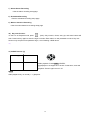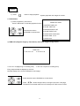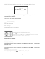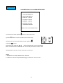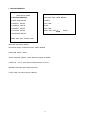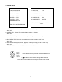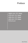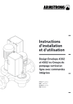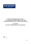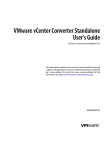
1
Thank you for purchasing our product. Please read this User Manual before using the product.
CCT715
4-Way Digital Video Recorder
User’
s Manual
Tip! If you have a problem setting up the CCT715 our top trouble
shooting tips are listed at the rear of these instructions;
Version V6
Safety Precautions
CAUTION
RIS K OF EL E CTR IC AL
S H O C K. D O NO T O P E N !
CA UT ION: T O RE DU CE TH E R IS K O F E L E C TR ICAL S HO CK ,
DO N O T R E M O V E C OV E R (O R BA CK), NO U S E R
S E RV ICE A BLE PA RT S R E FE R S E RV IC IN G TO
QU AL IFIE D S E RV IC E P E R S O NNE L .
This label may appear on the bottom of the unit due to space limitations.
The lightning flash with arrowhead symbol, within an equilateral triangle,
is intended to alert the user to the presence of insulated dangerous
voltage within the product’
s enclosure that may be sufficient magnitude
to constitute risk of electrical shock to persons.
The exclamation point within an equilateral triangle is intended to alert
the user to the presence of important operation and maintenance
(servicing) instructions in the literature accompanying the appliance.
WARNING: TO PREVENT FIRE OR SHOCK HAZARD, DO
NOT EXPOSE UNITS NOT SPECIFICALLY DESIGNED FOR
OUTDOOR USE TO RAIN OR MOISTURE.
Attention: installation should be performed by qualified service Personnel
only in accordance with the National Electrical Code or applicable local
codes.
Power Disconnect. Units with or without ON-OFF switches have power
supplied to the unit whenever the power cord is inserted into the power
source; however, the unit is operational only when the ON-OFF switch is
the ON position. The power cord is the main power disconnection for all
units.
“CAUTION: Danger of explosion if battery is incorrectly replaced.
Replace only with the same or equivalent type recommended by the
manufacturer. Dispose of used batteries according to the manufacturer‘
s
instruction.”
2
About this document
Before installing the stand alone DVR, be sure to thoroughly review and follow the instructions in this User
Manual. Pay particular attention to the parts marked NOTICE.
Before reading this document
1. This document is intended for both the administrator and users of this stand alone DVR Model.
2. This manual contains information for configuring, managing and using this stand alone DVR Model.
3. To prevent fire or electrical shock, do not expose the product to heat or moisture
4. Be sure to read this manual before using this stand alone DVR Model.
5. For questions and technical assistance on this product, contact your local dealer.
Recommendations on installation of the DVR unit
1. Check that the electricity supply at the place you want to install the DVR unit is stable and meets
our electricity requirements. Unstable electricity will cause malfunction of the unit and may damage
the unit.
It is recommended that this unit is connected to a power surge protection unit.
2. Several chips on the main board of the DVR unit and hard disk drive inside the unit generate heat,
and it must be properly discharged. Do not put any objects just beside exhaust port(fan) on the left
side of the unit and do not cover the opening (fresh air in-take) on the right side of the unit.
3. Put the DVR unit in a well-ventilated place and do not put heat generating objects on the unit. When
it is installed in a mounting rack together with other devices, please check that the built-in ventilation
fan in the rack is running properly.
3
Unit Description of Front Panel
COMPACT FLASH CARD READER
CHANNELS 1-4
4 QUAD SCREEN MODE BUTTON/ MODE FUNCTION KEY/ QUAD DISPLAY ON PLAYBACK
CHANNEL 1/2/3/4
CHANNEL 1/2/3/4 FULL SCREEN BUTTONS
FREEZE
PICTURE FREEZE MODE BUTTON
ZOOM
PICTURE ZOOM x 2 MODE BUTTON
W.MARK/AUTO
WATER MARK FUNCTION BUTTON/AUTO SEQUENCE MODE
BACKUP/PIP
IMAGE BACKUP BUTTON / PICTURE IN PICTURE MODE BUTTON
DIRECTION BUTTON UP
, PLAYBACK STOP BUTTON
REVERSE PLAYBACK BUTTON
STILL PLAYBACK
ENTER/AUDIO BUTTON - SUB MENU ENTER/ AUDIO ON/OFF
FORWARD PLAYBACK BUTTON
STILL PLAYBACK
DIRECTION BUTTON DOWN
MENU
PRESS THIS BUTTON TO DISPLAY MENU SETUP
ESC/LOCK
PLAY
SUB MENU EXIT BUTTON - KEY LOCK FUNCTION
PLAYBACK BUTTON
REC RECORD BUTTON
NOTE: VALUE CHANGES BUTTONS ARE FOUND UNDER CCT715 FLAP
T-SRH PLAY BACK TIME
SEARCH
4
REDUCE
INCREASE
Unit Description of Rear Panel
DC 12V 5A
5A 12V DC POWER IN
CAMx IN
CAMERAS IN 1 – 4
OUT
VIDEO LOOP THROUGH
75 OHM ON/OFF (HIGH/LOW ADJUST)
MONITOR OUTPUT
S – VIDEO (Y/C) MONITOR OUT
AUDIO OUT AUDIO CHANNEL OUTPUT
IN AUDIO CHANNEL INPUT
ALARM
ALARM CONNECTOR
ISP
RS232 CONNECTOR/FIRMWARE UPGRADE PORT
RS485
CONTROL KEYBOARD CONNECTOR
NOTE: PTZ NOT CURRENTLY AVAILABLE
5
Installation
1) Camera Connection
DC
LE VEL
Connect the camera to the CAMERA INPUT
V.P
CH1
CH2
CH3
CH4
CH1
CH2
CH3
CH4
V I DE O
DC
MON I TOR
VIDEO
on the Rear Panel of the 4 CH DVR.
LE NS
AC2 4V/DC12
Rear part of CAMERA
2) Monitor Connection (Composite Connection
Method)
Connect the monitor to the MONITOR OUT on
CH 1
C H2
CH3
CH4
CH 1
C H2
CH3
CH4
MONI TOR
VIDE O A
the Rear Panel of the 4 CH DVR.
IN
OUT
3) Monitor Connection
Connect S-VIDEO Monitor to MONITOR OUT
CH1
CH 2
CH3
CH4
CH1
CH 2
CH3
CH4
MONI TOR
on the Rear Panel of the 4 CH DVR.
VIDEO A
IN
OUT
4) Sensor Connection
Connect the Sensor to the SENSOR INPUT/
OUTPUT on the Rear Panel of the system
1.ALARM0
2.ALARM1
3.ALARM2
4.ALARM3
23.ALARM NC
24.ALARM NO
25.ALARM COM
5. ~ 19. GND
13,12,11,10,9,8,7,6,5,4,3,2,1
25,24,23,22,21,20,19,18,17,16,15,14
Relay output : COM+NC, COM+NO
Alarm input : Short-circuit between Alarm0, Alarm1, Alarm2 or Alarm3 and GND is recognized as
alarm by default.Alarm0~3 will be corresponding to Camera1~4.
NOTICE: Sensor input is RECOGNIZED as LOW when alarm signal is on a level with GND, and it is
recognized as HIGH when alarm signal is FLOATING or 5V. Following is internal circuit.
6
5
V
Internal Circuit
D1
Thus, there is a danger of damage, when the sensor input goes to a Negative level or voltage higher than
5V.
5) Hard Disk Installation
This 4 CH DVR is capable of accommodating a maximum of 2 internal hard drives.
- Hard Disk Master and Slave jumper pins must be set correctly, otherwise DVR will not function.
- 400 Gb Hard Drives are not compatible with this unit. Unit takes 2 x 300 Gb Hard Drives maximum.
1.
Remove the two cabinet screws from each side of the CCT715 case.
2.
Slide the lid backwards and lift off.
3.
The first or Master Drive is
fitted in the left compartment
looking from the front of the
CCT715. The second drive or
slave is fitted in the right
compartment.
4.
Identify the screws and brackets supplied.
These are used to secure
the brackets to the raised
pillars on the base
5.
These screws are used to
secure the brackets to the
hard drive
These screws are used to
secure case
Two brackets are used
for each hard drive
installed.
Attach a bracket to each side of a hard drive using the black screws without washers.
7
This drive will be the first/Master drive.
In order to set the Master it is necessary to
set the correct jumper connection. The
jumper connections are specified on the
hard drive.
If you are installing two hard drives, the
second hard drive must be set as the
Slave drive. Again the appropriate
jumper connection must be set. This
will also be specified on the hard drive.
6.
This shows two Hitachi Hard Disk Drives, the one on the left setup as Master and the one on the right
as the Slave.
HITACHI MASTER & SLAVE HARD DRIVES
MASTER JUMPER
SETTING
SLAVE JUMPER SETTING
7. The following shows two Maxtor Hard Disk Drives, the one on the left setup as Master and the one on the
right as the Slave.
8
MAXTOR SLAVE SETTING
NOTE: The jumper is
completely removed.
MAXTOR MASTER SETTING
8. Now connect the IDE Ribbon cable and the hard drive power supply plug. These cables have a keyed
side so that they can only fit one way round. Note that the ribbon cable has a red edge that faces the red
cable of the power supply plug. The left ribbon cable and power plug are for the Master and the right
ribbon cable and power plug are used for the Slave.
HARD DRIVE PILLARS
9.
The hard drive/s can now be fitted to the base of the CCT715. The Master is fitted in the left hand space
and if the second Slave drive is fitted, this is fitted in the right hand space. There are four pillars to
attach each hard drive. The black screws with washers are used for this.
10. Now slide on top case and using extra chrome screws supplied, secure sides and back.
9
Picture
Full screen or quad screen display
Press
quad button to display 4 quad screen.
Press numeric 1 / 2 / 3 / 4 buttons to display a desired camera image in full screen.
1.) FREEZE Mode
1. In live and the quad mode press
Press
(FREEZE) button to freeze image.
again to cancel freeze mode.
2. On the full screen display, press
(FREEZE) button to freeze full screen image.
2.) Zoom Mode(Display Enlargement.)
Go to full screen mode with numeric buttons in live or playback
mode, then press ZOOM button to display screen Enlargement.
Use
button to move position.
3.) Auto Mode
Press
(AUTO) button to start screen auto sequencing, and press it again to cancel auto mode.
4.) W.MARK. Water Mark mode.
Water Mark protection function on or off. To prevent hackers using special software to modify the image data.
System SetupàWatermark Check mode On. Press W.Mark button to on or off. (Playback mode only)
5.) PIP (PICTURE IN PICTURE)
1.) Press
(PIP) button. Press
(AUTO) button to start sub-screen auto sequencing.
Main picture
Sub picture
2) With
button, select the main channel screen, press
small screen.
10
button to select desired camera channel in
6.) BACKUP / PIP. Image backup mode.(Image backup works in playback mode only.)
Locate the playback point you want. Press BACKUP, the BACKUP CAUTION window pops up. Press
ENTER to begin data back up. Capacity of CF card is not limited, but the maximum capacity display is
9999MB.
In playback mode, press BACKUP:
Lower-Right corner of the screen:
** BACKUP CAUTION **
ALL DATA IN THE CF CARD
WILL BE CLEARED.
PRESS [ENTER] TO BACKUP.
PRESS [BACKUP] TO
0000M / 0256MB
0000MB / 0256 (Presently back up progress / Total capacity of CF card)
Important:
If the CF card contains old data, please format CF card to FAT or FAT32 on a computer before inserting in
DVR CF card slot. Otherwise, DVR will not detect correct CF card format. Any brand of CF card is
acceptable.
Additional:
During playback, if a CF card is full or if user presses the BACKUP button, the screen will display a “PAUSE”
caption. User then takes out the CF card then saves data to P.C hard disk using the USB connection via a
USB reader. After this, re- insert the CF card in the DVR slot, and press BACKUP again. Press ENTER to
continue backup or backup button to cancel. Note that this DVR will display recorded date and time on the
recorded images.
** BACKUP CAUTION **
PAUSE
ALL DATA IN THE CF CARD
WILL BE CLEARED.
PRESS [ENTER] TO BACKUP.
PRESS [BACKUP] TO CANCEL.
To play back the data after loading to the PC hard drive, it is recommended that the Viewer Software
supplied for this DVR is used for this purpose.
Whilst the CF card can be used to download a file larger than the CF card capacity using the above method
it may be a long process if large files are required for evidence. It may be preferable to backup a large file to
a VCR by recording using the monitor output.
11
7.) Alarm Sensor Recording
>See the alarm recording setup page
8.) Scheduled Recording
>See the scheduled recording setup page
9.) Motion detection Recording
>See the motion detection recording setup page
10.) Key Lock function
>In the Live or Playback mode, press
(lock). Only numeric, freeze, auto, pip, and zoom buttons will
work. Press lock key again to enter the login-in window. Enter admin or user password to unlock. Key lock
function only accepts correct password log-in, even following a DVR reboot.
10.)
11.) AUDIO function ))))
))))
xxxxxxxxx
Audio playback: Press AUDIO / ENTER,
a ))))))))displays on the Upper-left of screen. At that time, audio will
playback. Press it again to turn it off.
Notice
Audio playback only on normal ( x 1 ) playback.
12
Playback
1. Playback Mode
1) Press
PLAY
button to begin playback.
System plays back the images in reverse.
2. T-SRH button
1) T-SRH: Playback by time search.
MAIN PLAY PAGE
Press T-SRH button to activate playback function.
1.MASTER TIME LIST
2.SLAVE TIME LIST
3.MASTER EVENT LIST
Press direction button
UP/DOWN to choose items.
4.SLAVE EVENT LIST
5.GOTO DATE: 2004/12/31
6.GOTO TIME: 12:12
7.GOTO PLAY
1) TIME LIST (Playback image by Time-Search): Recorded images list (by hours)
TIME LIST
Y/M/DH/M
Y / M / D H / M (Beginning of recording time)
Y/M/DH/M
Y / M / D H / M (End of recording time)
Every playback data list displays by the hour.
No page display limit. 10 items displayed on each page.
Press direction button UP/DOWN to choose items.
Press
values change button to change to previous / next page.
The buttons are located under the CCT715 flap on the R/H corner of DVR
13
2) EVENT LIST (Alarm List): Event source- Video loss / Alarm trigger / Motion / Record
EVENT LIST
NO Y / M / D H / M _ _ _ _ Motion
10 items displayed on each page. A total of 5000 items displayed across 500 pages. Note that a maximum
of 5000 items are only displayed.
Y / M / D H / M : Year / Month / Day Hour / Minute
_ _ _ _: Event Channel Display.
>1 CH, 2 CH, 3 CH, 4 CH.
Motion: Event type.
>Includes Motion / Alarm / V-Loss / Record
Press direction button UP/DOWN to choose items.
Press
values change button to change page. The buttons are located
under the CCT715 flap on the R/H corner of DVR
>Special time search playback:
Go TO DATE: 2002/12/12
-Choose year / month / day
>Press direction button Left / Right to choose items, press values change button
to change value.
GOTO TIME: 12:12
-Choose hour and minute
>Press direction button Left / Right to choose items, press values change button
GOTO PLAY
-Press ENTER button to start playback.
Notice: Playback speed change by
. . Speed is x 1, x 2, x 4, x 8, x 16.
14
to change value.
FUNCTION SETUP
LOGIN
1) Press
MENU
button to enter menu. You can do system function setup in MENU.
2) Enter Password Menu
Default password (Account-Admin) : 44444
CHECK PASSWORD MENU
Default password (Account-User) : 11111
PASSWORD (*****)
3) Press numeric (1 ~ 4 )button or remote controller ( 1 ~ 9 )to choose password.
4) Remote controller function buttons are same as DVR panel function buttons.
15
Basic Operation
Press MENU button to enter MAIN SETUP PAGE.
MAIN SETUP PAGE
1. HDD INFORMATION
2. DATE-TIME SETUP
3. DISPLAY SETUP
4. CAMERA SETUP
5. BUZZER SETUP
6. SYSTEM SETUP
7. ADVANCED SETUP
MENU, ESC: EXIT, ENTER: RUN
1) Use direction button up/down
2) Press
button to select setup item.
button to enter into sub-menu function setup.
3) Press sub-menu item with direction button up/down
or left/right
button.
And change the value with
values change button or turn inner-shuttle.
Note: The buttons are located under the CCT715 flap on the R/H corner of DVR
4) Press ESC to go back to main / sub menu or exit menu.
Notice:
1. ADMIN level can setup all DVR menu functions.
2. USER level cannot setup ADVANCED page of DVR main menu function.
16
1. HDD INFORMATION
MAIN SETUP PAGE
1. HDD INFORMATION
POSITION SIZE USED BRAND
2. DATE-TIME SETUP
MASTER
3. DISPLAY SETUP
LAST TIME
4. CAMERA SETUP
SLAVE
5. BUZZER SETUP
LAST TIME
6. SYSTEM SETUP
MENU, ESC: EXIT,
7. ADVANCED SETUP
MENU, ESC: EXIT, ENTER: RUN
Hard Disk Information Display.
Information display: POSITION SIZE USED BRAND
>POSITON: Master / Slave
>SIZE: Hard Disk capacity. xxGB. Maximum display is 999GB
>USED: 00 ~ 100 %. Hard disk overwrites always on 100 %.
>BRAND: DVR auto detect hard disk brand.
>LAST TIME: The last record time display.
17
:PAGE
2. DATE-TIME SETUP
MAIN SETUP PAGE
DATE-TIME SETUP PAGE
1. HDD INFORMATION
1. DATE 2000 / 00 / 00
2. DATE-TIME SETUP
2. TIME
3. DISPLAY SETUP
3. DISPLAY AT xx LINE(S)
4. CAMERA SETUP
4. DAYLIGHT SAVING
5. BUZZER SETUP
MENU, ESC:EXIT,
:MODIFY
1. DATE: > YYYY/MM/DD
2. TIME: > Use direction button up/down to choose position & values change button to change date and time
values.
3. DISPLAY AT xx LINE(S)
-Date and Time position on screen xx line(s). 00 ~ 23.
4. DAY LIGHT SAVING:
-Day light saving function on or off.
The Day light Savings function that enable two special updates when it is set to “ON”.
On the first Sunday in April, the time increments from 1:59:59 AM to 3:00:00 AM.
On the last Sunday in October when the time first reaches 1:59:59 AM, it changes to 1:00:00 AM.
Press direction button up/down/left/right to choose items or move date-time position.
18
3. DISPLAY SETUP
MAIN SETUP PAGE
DISPLAY SETUP PAGE
1. HDD INFORMATION
1. DATE-TIME
ON
2. DATE-TIME SETUP
2. CAMERA TITLE
ON
3. DISPLAY SETUP
3. PB DATE-TIME
ON
4. CAMERA SETUP
4. PB CAMERA TITLE ON
5. BUZZER SETUP
5. DVR STATUS
ON
6. SYSTEM SETUP
6. BORDER SET
WHITE
7. ADVANCED SETUP
MENU, ESC:EXIT,
:MODIFY
MENU, ESC: EXIT, ENTER: RUN
1. DATE-TIME: Date and Time caption display mode on or off setup.
>ON / OFF
2. CAMERA TITLE: Camera Title caption display mode on or off setup.
>ON / OFF
3. PB DATE-TIME: Play back date and time caption display mode on or off setup.
>ON / OFF
4. PB CAMERA TITLE: Play back camera title caption display mode on or off setup.
>ON / OFF
5. DVR STATUS: DVR system, record, playback, audio caption display mode on or off setup.
>ON / OFF
6. BORDER SET: Border colour WHITE / DARK / BLACK / GREY.
Press direction button up/down to choose the desired item.
Press
values change button to change values. Note:The
buttons are located under the CCT715 flap on the R/H corner of DVR
19
4. CAMERA SETUP
MAIN SETUP PAGE
1. HDD INFORMATION
CAMERA SETUP PAGE
2. DATE-TIME SETUP
1. COLOUR SETUP
3. DISPLAY SETUP
2. TITLE SETUP
4. CAMERA SETUP
3. SCREEN POSITION SETUP
5. BUZZER SETUP
4. V-LOSS DISPLAY SETUP
6. SYSTEM SETUP
5. VIDEO MASK SETUP
7. ADVANCED SETUP
MENU, ESC: EXIT, ENTER: RUN
MENU, ESC: EXIT, ENTER: RUN
(1.) COLOUR SETUP
CAMERA-COLOUR SETUP PAGE
** CH CAMERA 01
CAMERA SETUP
1. COLOUR SETUP
1. BRIGHTNESS 00
2. TITLE SETUP
2. CONTRAST 00
3. SCREEN POSITION SETUP
3. SATURATION 00
4. V-LOSS DISPLAY SETUP
4. HUE
5. VIDEO MASK SETUP
5. GAIN
00
00
>>DEFAULT RESET<<
CAMERA-COLOUR SETUP : Adjust Camera Image
CH NUMBER
: Select camera
BRIGHTNESS
: Adjust screen brightness
(-31~ +32)
CONTRAST
: Adjust colour contrast
(-31~ +32)
SATURATION
: Adjust colour saturation
(-31~ +32)
HUE
: Adjust colour hue
(-31~ +32)
GAIN
: Adjust image signal level
(-31~ +32)
>>DEFAULT RESET<< : Press ENTER button to reset DVR values.
Press direction button up/down to choose items.
Press
values change button to change values.
Note:The buttons are located under the CCT715 flap on the
R/H corner of DVR
The correct adjustment in COLOUR setup will improve picture quality displayed. We recommend that each
element of the colour adjustment is setup for each camera and monitor connected to the DVR.
20
(2.) TITLE SETUP: Input TITLE of each camera. 18 characters can be input.
CAMERA-TITLE SETUP PAGE
CAMERA SETUP
CH1 (CAM01
)
1. COLOUR SETUP
CH2 (CAM02
)
2. TITLE SETUP
CH3 (CAM03
)
3. SCREEN POSITION SETUP
CH4 (CAM04
)
4. V-LOSS DISPLAY SETUP
5. VIDEO MASK SETUP
MENU, ESC: EXIT:
: MODIFY
Press direction button up/down/left/right to choose items and position.
Press
values change button to change values. Note:The buttons are
located under the CCT715 flap on the R/H corner of DVR
Characters choose:
Numeric: 0 / 1 / 2 / 3 / 4 / 5 / 6 / 7 / 8 / 9
Capital letter: A / B / C / D / E / F / G / H / I / J / K / L / M / N / O / P / Q / R / S / T / U / V / W / X / Y / Z
21
(3.) SCREEN POSITION SETUP
**** SCREEN POSITION****
UP
CAMERA SETUP
1. COLOUR SETUP
LEFT
RIGHT
2. TITLE SETUP
3. SCREEN POSITION SETUP
4. V-LOSS DISPLAY SETUP
DOWN
5. VIDEO MASK SETUP
ENTER for Default
ESC to QUIT
1.
Press direction buttons up/down/left/right to move screen position.
2. Press ENTER button for default.
3. Press ESC button to quit.
22
(4.) V-LOSS DISPLAY SETUP
VLOSS SETUP PAGE
**VLOSS FUNCTION:
CAMERA SETUP
1. COLOUR SETUP
CH1 VLOSS DISPLAY
2. TITLE SETUP
CH2 VLOSS DISPLAY
3. SCREEN POSITION SETUP
CH3 VLOSS DISPLAY
4. V-LOSS DISPLAY SETUP
CH4 VLOSS DISPLAY
5. VIDEO MASK SETUP
MENU, ESC: EXIT:
: MODIFY
** VLOSS FUNCTION: ON / OFF
CH1 VLOSS DISPLAY: ON / OFF
CH2 VLOSS DISPLAY: ON / OFF
CH3 VLOSS DISPLAY: ON / OFF
CH4 VLOSS DISPLAY: ON / OFF
Press direction buttons up/down/left/right to choose items.
Press
values change button to change values. Note:The buttons are
located under the CCT715 flap on the R/H corner of DVR
23
(5.) VIDEO MASK SETUP
VIDEO MASK SETUP PAGE
CAMERA SETUP
CH1 VIDEO MASK
1. COLOUR SETUP
CH2 VIDEO MASK
2. TITLE SETUP
CH3 VIDEO MASK
3. SCREEN POSITION SETUP
CH4 VIDEO MASK
4. V-LOSS DISPLAY SETUP
5. VIDEO MASK SETUP
MENU, ESC: EXIT:
: MODIFY
CH1 VIDEO MASK: ON / OFF
CH2 VIDEO MASK: ON / OFF
CH3 VIDEO MASK: ON / OFF
CH4 VIDEO MASK: ON / OFF
MASK means this channel would not display on the live screen, but it still recording.
Press direction buttons up/down/left/right to choose items.
Press
values change button to change values. Note:The buttons are
located under the CCT715 flap on the R/H corner of DVR
24
5. BUZZER SETUP
BUZZER SETUP PAGE
MAIN SETUP PAGE
1. HDD INFORMATION
**SYSTEM BUZZER ON
2. DATE-TIME SETUP
3. DISPLAY SETUP
4. CAMERA SETUP
5. BUZZER SETUP
BUTTON BUZZER
ON
ALARM BUZZER
ON
MOTION BUZZER
ON
VLOSS BUZZER
ON
6. SYSTEM SETUP
7. ADVANCED SETUP
MENU, ESC: EXIT:
MENU, ESC: EXIT, ENTER: RUN
**SYSTEM BUZZER: Buzzer function
>ON / OFF
1. BUTTON BUZZER?
> ON / OFF
2. ALARM BUZZER?
> ON / OFF
3. MOTION BUZZER?
> ON / OFF
4. VLOSS BUZZER?
> ON / OFF
Press direction buttons up/down to BUZZER SETUP items.
Press
values change button to change
values.Note:The buttons are located under the
CCT715 flap on the R/H corner of DVR
25
: MODIFY
6. SYSTEM SETUP
MAIN SETUP PAGE
SYSTEM SETUP
1. HDD INFORMATION
1. DWELL INTERVAL
2. DATE-TIME SETUP
2. LANGUAGE
3. DISPLAY SETUP
3. VIDEO INPUT
4. CAMERA SETUP
4. WATERMARK CHECK
5. BUZZER SETUP
5. RS-485 ID
6. SYSTEM SETUP
6. RS-485 PROTOCOL
7. ADVANCED SETUP
7. RS-485 BAUD RATE
MENU, ESC: EXIT, ENTER: RUN
MENU, ESC: EXIT:
: MODIFY
SYSTEM SETUP
1. DWELL INTERVAL:
- 0 ~ 999SEC
2. LANGUAGE
- ENGLISH / CHINESE / JAPANESE
3. VIDEO INPUT: NTSC / PAL system detection,
- AUTO / NTSC / PAL
4. WATERMARK CHECK:
-ON / OFF
5. RS-485 ID:
- 01 ~ 16
6. RS-485 PROTOCOL
- KEYBOARD / LILIN / PELCO-P / PELCO-D / NICECAM
7. RS-485 BAUD RATE
- 1200 / 2400 / 4800 / 9600
RS-485 ID and protocol is the command for system control keyboard. Currently PTZ equipment is not
operational with this equipment.
Press direction buttons up/down to choose items.
Press
values change button to change values.
Note:The buttons are located under the CCT715 flap on
the R/H corner of DVR
26
8. ADVANCED SETUP
ADVANCED SETUP PAGE
MAIN SETUP PAGE
1. ALARM SETUP
1. HDD INFORMATION
2. MOTION SETUP
2. DATE-TIME SETUP
3. RECORD SETUP
3. DISPLAY SETUP
4. PASSWORD SETUP
4. CAMERA SETUP
5. HDD FORMAT
5. BUZZER SETUP
6. FACTORY DEFAULT
6. SYSTEM SETUP
7. ADVANCED SETUP
MENU, ESC: EXIT, ENTER: RUN
ALARM SETUP PAGE
ADVANCED SETUP PAGE
1. ALARM SETUP
1. ALARM FUNCTION
2. MOTION SETUP
ON / OFF
2. ALARM DURATION
3. RECORD SETUP
3. ALARM RELAY SETUP<
4. PASSWORD SETUP
4. ALARM POLARITY SETUP<
5. HDD FORMAT
6. FACTORY DEFAULT
MENU, ESC: EXIT:
: MODIFY
1. Alarm function: ON / OFF
2.Alarm duration: 0 ~ 999 secs Record length interval - Default is set to 10 secs
ALARM POLARITY SETUP PAGE
ALARM RELAY SETUP PAGE
ALARM01: NO / NC / OFF
ALARM01 : ON / OFF
ALARM02 : ON / OFF
ALARM03 : ON / OFF
ALARM04 : ON / OFF
ALARM02: NO / NC / OFF
ALARM03: NO / NC / OFF
ALARM04: NO / NC / OFF
Press direction buttons up/down to choose items.
Press
values change button to change values.
Note:The buttons are located under the CCT715 flap on
the R/H corner of DVR
27
2. MOTION SETUP
MOTION SETUP PAGE
ADVANCED SETUP PAGE
**MOTION FUNCTION ON
1. ALARM SETUP
**MOTION DURATION
2. MOTION SETUP
**CHANNEL NUMBER
3. RECORD SETUP
1. SENSITIVITY
4. PASSWORD SETUP
2. VELOCITY
5. HDD FORMAT
3. MOTION ACTIVE
6. FACTORY DEFAULT
4. MOTION RELAY
5. MOTION AREA SETUP
MENU, ESC: EXIT:
MOTION SETUP
**MOTION FUNCTION (set for all channels)
-ON / OFF
**MOTION DURATION
-0 ~ 999 secs
**CHANNEL NUMBER
Ch 1 / Ch 2 / Ch 3 / Ch 4
1. SENSITIVITY Adjusts motion Detection Sensitivity.
-1 ~ 32 (low àhigh)
2. VELOCITY Adjusts motion object slow /fast speed detection
-1 ~ 10 (slow speedàfast speed)
3. MOTION ACTIVE (For each channel)
-ON / OFF. Motion detect option for each channel.
4. MOTION RELAY
-ON / OFF
5. >MOTION AREA SETUP<
Press direction buttons up/down to choose items.
Press
values change button to change values.
Note:The buttons are located under the CCT715 flap on the
R/H corner of DVR
28
: MODIFY
> MOTION AREA SETUP <
All area detect with factory default. Press quad button to change mode and then increase or reduce.
Press
For example:
value change button to reduce. Note:The buttons are
located under the CCT715 flap on the R/H corner of DVR
Press
value change button to increase. Note:The
buttons are located under the CCT715 flap on the R/H corner
Add lattices
of DVR
Icon:
Press
to increase area, press
to reduce area.
Icon:
Press Up / Down / Left / Right direction key to move, press
to increase lattices; press
lattices.
Icon: +
Press Up / Down / Left / Right direction key to move and increase area.
Icon: X
Press Up / Down / Left / Right direction key to move and reduce area.
29
to reduce
3. RECORD SETUP
ADVANCED SETUP PAGE
RECORD SETUP
1. ALARM SETUP
1. HDD FULL
2. MOTION SETUP
2. RECORD SPEED
3. RECORD SETUP
3. RECORD MODE
4. PASSWORD SETUP
4. RECORD AUDIO
5. HDD FORMAT
5. QUALITY
6. FACTORY DEFAULT
6. SCHEDULE SETUP
MENU, ESC: EXIT:
: MODIFY
RECORD SETUP
1)
When hard disk is full, OVERWRITE will allow
HDD FULL:
-OVERWRITE / STOP REC
2)
overwrite of earliest data files: STOP REC will halt machine.
RECORD SPEED: Record FPS (Frames Per Second) setup
1/30, 1/15, 1/10, 1/5, 1/3, 1/2, 1, 2, 3.13, 5, 8.33, 12.5, 25, 50, 100. For 4 cameras
3)
RECORD MODE: Record mode setup. (ALWAYS = default. This does not allow Schedule or Event
Recording).
-ALWAYS / SCHEDULE / EVENT / EVENT ON SCHEDULE / EVENT + SCHEDULE
4)
RECORD AUDIO: Audio record setup
-ON / OFF
5)
QUALITY: Record image quality setup
- SUPER / HIGH / FINE / NORMAL / LOW
6)
SCHEDULE SETUP
Press direction buttons up/down to choose items.
Press
values change button to change values.
The buttons are located under the CCT715 flap on the
R/H corner of DVR
30
Additional:
2. RECORD SPEED. 1/30, 1/15, 1/10, 1/5, 1/3, 1/2, 1, 2, 3.13, 5, 8.33, 12.5, 25, 50, 100.
Record speed of 100 is for Real Time recording. Playback displays 25 frames per channel on FULL screen
and 12.5 frames per channel on a 4 – split screen.
3. RECORD MODE. ALWAYS / SCHEDULE / EVENT / EVENT ON SCHEDULE / EVENT + SCHEDULE.
-Always: 24 hours recording. Manual record or stop.
-Schedule: Date and time schedule recording mode.
-Event: Alarm / Motion / V-Loss event mode recording.
-Event on schedule: Event record only during scheduled times.
-Event + Schedule: Event recording when schedule set. Events are recorded regardless of schedule time
set.
4. RECORD AUDIO: ON / OFF.
-Set Audio to ON for audio recording.
SPECIAL NOTE:
In order to start any event/schedule recording you must press the REC button on the front of the unit
after setting the above.
31
>SCHEDULE SETUP<
RECORD SETUP
1. HDD FULL
2. RECORD SCHEDULE
Press direction buttons up/down to
3. RECORD MOTION
SCHEDULE items.
4. RECORD ALARM
5. RECORD POWER ON
Press
values change button to change values.
6. RESOLUTION
Note:The buttons are located under the CCT715 flap on
>SCHEDULE SETUP<
the R/H corner of DVR
>RECORD SPEED SETUP<
Factory default is everyday. This schedules
continuous time recording.
SCHEDULE SETUP
MODE INDICATOR
CURSOR STEP
30MIN / 6MIN
/++/--
SUN
MON
TUE
WED
THU
FRI
SAT
Press direction buttons up/down/left/right to see
date and time difference.
Press
values change left/right button to change 30MIN or 6 MIN intervals.
(Press Value Change Buttons under CCT715 Flap)
++ / - - : Increase / Reduce. Every day record = factory default.
MODE KEY
On
, use up/down button to choose day, press mode button to change
+ + or - -. After, use direction left / right button to start increase or reduce time area.
32
SCHEDULE SETUP
CURSOR STEP
SUN
MODE =
or ++
or - -
00:00 01:00 02:00 03:00 04:00 05:00 06:00 07:00 08:00 09:00 10:00 11:00 12:00 13:00 14:00 15:00 16:00 17:00 18:00 19:00 20:00 21:00 22:00 23:00
00:30 01:30 02:30 03:30 04:30 05:30 06:30 07:30 08:30 09:30 10:30 11:30 12:30 13:30 14:30 15:30 16:30 17:30 18:30 19:30 20:30 21:30 22:30 23:30
MON
00:00 01:00 02:00 03:00 04:00 05:00 06:00 07:00 08:00 09:00 10:00 11:00 12:00 13:00 14:00 15:00 16:00 17:00 18:00 19:00 20:00 21:00 22:00 23:00
00:30 01:30 02:30 03:30 04:30 05:30 06:30 07:30 08:30 09:30 10:30 11:30 12:30 13:30 14:30 15:30 16:30 17:30 18:30 19:30 20:30 21:30 22:30 23:30
TUE
00:00 01:00 02:00 03:00 04:00 05:00 06:00 07:00 08:00 09:00 10:00 11:00 12:00 13:00 14:00 15:00 16:00 17:00 18:00 19:00 20:00 21:00 22:00 23:00
00:30 01:30 02:30 03:30 04:30 05:30 06:30 07:30 08:30 09:30 10:30 11:30 12:30 13:30 14:30 15:30 16:30 17:30 18:30 19:30 20:30 21:30 22:30 23:30
WED
00:00 01:00 02:00 03:00 04:00 05:00 06:00 07:00 08:00 09:00 10:00 11:00 12:00 13:00 14:00 15:00 16:00 17:00 18:00 19:00 20:00 21:00 22:00 23:00
00:30 01:30 02:30 03:30 04:30 05:30 06:30 07:30 08:30 09:30 10:30 11:30 12:30 13:30 14:30 15:30 16:30 17:30 18:30 19:30 20:30 21:30 22:30 23:30
THU
00:00 01:00 02:00 03:00 04:00 05:00 06:00 07:00 08:00 09:00 10:00 11:00 12:00 13:00 14:00 15:00 16:00 17:00 18:00 19:00 20:00 21:00 22:00 23:00
00:30 01:30 02:30 03:30 04:30 05:30 06:30 07:30 08:30 09:30 10:30 11:30 12:30 13:30 14:30 15:30 16:30 17:30 18:30 19:30 20:30 21:30 22:30 23:30
FRI
00:00 01:00 02:00 03:00 04:00 05:00 06:00 07:00 08:00 09:00 10:00 11:00 12:00 13:00 14:00 15:00 16:00 17:00 18:00 19:00 20:00 21:00 22:00 23:00
00:30 01:30 02:30 03:30 04:30 05:30 06:30 07:30 08:30 09:30 10:30 11:30 12:30 13:30 14:30 15:30 16:30 17:30 18:30 19:30 20:30 21:30 22:30 23:30
SAT
00:00 01:00 02:00 03:00 04:00 05:00 06:00 07:00 08:00 09:00 10:00 11:00 12:00 13:00 14:00 15:00 16:00 17:00 18:00 19:00 20:00 21:00 22:00 23:00
00:30 01:30 02:30 03:30 04:30 05:30 06:30 07:30 08:30 09:30 10:30 11:30 12:30 13:30 14:30 15:30 16:30 17:30 18:30 19:30 20:30 21:30 22:30 23:30
For example: TUE ~ SAT, all day schedule time recording, but SUN 07:00 ~ 22:00 and MON 01:30 ~ 23:30
schedule recording. User can press ENTER to see the schedule time area difference.
1. ENSURE MODE KEY =
QUICK GUIDE
2. PRESS UP- KEY ON SHUTTLE - THIS SHOULD SHOW AN ARROW POINTING TO 00:00 SUNDAY.
3. PRESS RIGHT KEY ON SHUTTLE TO POSITION WHERE RECORDING TO START. NOTE THAT DARK LINE SHOWS
RECORDING TIME SCHEDULED.
4. PRESS MODE KEY = ++ OR - - (++ SETS RECORD TIME INTERVAL & - - RESETS IT)
PRESS LEFT OR RIGHT KEY ON SHUTTLE TO INCREASE/DECREASE SCHEDULE TIME.
5. APPLY SCHEDULE TO EACH DAY –SUNDAY THROUGH TO SATURDAY..
6. NOW PRESS ESCAPE UNTIL YOU RETURN TO FIRST MENU PAGE THEN PRESS MENU TO RETURN TO NORMAL
CAMERA DISPLAY.
7. NOW TO START RECORDING PRESS THE REC (RECORD) BUTTON ON THE FRONT OF THE UNIT.
33
5. PASSWORD SETUP
ADVANCED SETUP PAGE
1. ALARM SETUP
PASSWORD SETUP PAGE
2. MOTION SETUP
3. RECORD SETUP
4. EVENT
5. PASSWORD SETUP
1. LEVEL:(
)
2. ADMIN:(
)
3. USER :(
)
6. HDD FORMAT
7. FACTORY DEFAULT
Press direction buttons up/down/left/right to
Choose items position.
1)
Press
LEVEL (Log In level ID type setup)
values change button to change
values.
>NONE / ADMIN / USER
-ADMIN:
-USER
-NONE, user does not need to insert password before enter in MENU.
2)
ADMIN password
>44444 (Factory Default)
3)
USER password
Notice:
Password always 5 character input, cannot accept < 5 characters
>11111 (Factory Default)
Press direction buttons up/down/left/right to choose items position.
Press numeric (1 ~ 4 )button or remote controller ( 1 ~ 9 )to choose password.
CAUTION: DO NOT USE 0 IN PASSWORD FIELD
Choose ADMIN: Only admin password can login to Advanced Menu.
Choose USER: Both user and admin passwords can login to menu but user password cannot
access Advanced Menu.
34
6. HDD FORMAT
ADVANCED SETUP PAGE
Press direction buttons up/down to
HDD FORMAT items position.
Press ENTER to format all HDD.
1. ALARM SETUP
2. MOTION SETUP
Caution: User can only format HDD when
record and playback halted.
3. RECORD SETUP
4. EVENT
5. PASSWORD SETUP
6. HDD FORMAT
7. FACTORY DEFAULT
à HDD FORMAT CAUTION!! :
** HDD FORMAT CAUTION!!**
Press ENTER button to format hard disk.
ALL DATA IN HDD WILL BE
DESTROYED!!
Press ESC button to cancel hard disk format
PRESS [ENTER] TO FORMAT.
PRESS [ESC] TO CANCEL.
7. FACTORY DEFAULT
ADVANCED SETUP PAGE
1. ALARM SETUP
Press direction buttons up/down to
FACTORY DEFAULT items position.
2. MOTION SETUP
3. RECORD SETUP
Press ENTER to restore.
4. EVENT
5. PASSWORD SETUP
6. HDD FORMAT
7. FACTORY DEFAULT
** CAUTION!!**
Press ENTER button to restore.
ALL SETUP VALUE WILL BE CLEAR,
AND RESTORE FACTORY DEFAULT!!
Press ESC button to cancel.
PRESS [ENTER] TO RESTORE.
PRESS [ESC] TO CANCEL.
35
CF card data read on PC
1. CD folder, save setup.exe to PC hard disk
or double click it.
2. Install Shield Wizard processing.
36
3. Click Next.
4. Choose folder.
37
5. After choose folder, click OK.
6. Click install to start.
38
7. Installing
8. Click Finish
39
To Open Video Viewer Go to
StartàProgramà Video VieweràVideo Viewer
Using left mouse button click “Local Search”.
Using left mouse button click the folder icon.
40
Choose new removable hard diskà BACKUP.DVR file. àOPEN. (Drive letters may vary).
Using left mouse button click the play icon.
Full Screen
41
Quad Screen
Icon:
Folder
Play
Stop
First
Forward / Reverse
End
Still playback
Camera Positions:
To change the image that is being displayed click the right mouse button on a image then choose 1~4 to
display that cameras image in that position.
For example, using the right mouse button to bring up the menu select “4”to change to that camera.
42
Function Bar:
Settings:
Video Format: PAL or NTSC
Choose Codec: AVI encode format
Show Watermark: Watermark function on or off.
43
Video Format:
For UK use PAL format.
Choose Codec: File format
Confirm
Cancel
Information
NOTE:
The Microsoft Windows
Media Video 9 is the
plug-in Media Player
Decoder software & not
the Media Player
Application.
Half and Full screen select
and record frame rate 1 ~ 25
Note: Frame/Sec must be set to same as the DVR is recording, otherwise it may give unexpected results.
Show Watermark: Watermark function on or off.
To check if file has been modified or not.
44
AVI file save:
AVI button: AVI file save.
Choose Folder and
type file name
Click save
Choose which Cameras you would like to save as AVI, click ok.
45
AVI red light on, record mode enabled
Once the AVI light has turned red click the play button to start recording.
Press the AVI Button
to stop recording.
JPG file save:
Use this to save still images
Help
Choose camera 1~4 or save all.
46
Choose folder and type in file name, click save.
Note: Single channel only, no saving quad pictures. Choosing ‘
save all’will save individual pictures.
.
47
Hard Disk Data Read
1.Take HDD out of DVR to a personal computer. Make sure hard disk in P.C is Master or Slave, switch Hard
disk jumper to Master or Slave.
2. Power on computer. You do not need to setup BIOS, just login to windows system.
3. Start > Program
> Video Viewer
Left click mouse button
Click here for hard disk list.
Click the correct DVR hard disk.
Data will not be lost if wrong HDD
selected.
48
Hard Disk list on:
After selecting the correct hard disk, user can read data as
per the previous instructions.
49
Record Time Table
Record Quality LOW
80Gb
160Gb
250Gb
300Gb
500Gb
600Gb
100
21.7hrs
1.8dys
2.8dys
3.4dys
5.7dys
6.9dys
50
21.7hrs
1.8dys
2.8dys
3.4dys
5.7dys
6.9dys
25
1.8dys
3.6dys
5.6dys
6.8dys
11.3dys
13.6dys
12.5
3.6dys
7.3dys
11.4dys
13.7dys
22.8dys
27.4dys
8.33
5.4dys
10.9dys
17dys
20.4dys
1.1mths
1.3mths
5
11.1dys
22.2dys
1.1mths
1.3mths
2.2mths
2.6mths
3.13
18.5dys
1.1mths
1.8mths
2.2mths
3.7mths
4.4mths
2
26.4dys
1.7mths
2.6mths
3.2mths
5.3mths
6.4mths
1
1.7mths
3.4mths
5.4mths
6.5mths
10.8mths
1yr
FPS
Record Time Table
Record Quality NORMAL
80Gb
160Gb
250Gb
300Gb
500Gb
600Gb
100
18.6hrs
1.5dys
2.4dys
2.9dys
4.8dys
5.8dys
50
18.6hrs
1.5dys
2.4dys
2.9dys
4.8dys
5.8dys
25
37hrs
3dys
4.8dys
5.7dys
9.6dys
11.5dys
12.5
3dys
6.1dys
9.6dys
11.5dys
19.2dys
23.1dys
8.33
4.6dys
9.2dys
14.4dys
17.3dys
28.9dys
1.1mth
5
9.2dys
18.5dys
28.9dys
1.1mth
1.8mth
2.2mth
3.13
15.4dys
30.8dys
1.5mth
1.8mth
3.1mth
3.7mth
2
23.1dys
1.4mth
2.3mth
2.8mth
4.6mth
5.6mth
1
1.4mth
2.9mth
4.6mth
5.6mth
9.3mth
11.2mth
FPS
Record Time Table
Record Quality FINE
80Gb
160Gb
250Gb
300Gb
500Gb
600Gb
100
16.8hrs
33.6hrs
2.1dys
2.6dys
4.3dys
5.2dys
50
16.8hrs
33.6hrs
2.1dys
2.6dys
4.3dys
5.2dys
25
33.6hrs
2.8dys
4.3dys
5.2dys
8.7dys
10.5dys
12.5
2.8dys
5.6dys
8.7dys
10.5dys
17.5dys
21dys
8.33
4.2dys
8.4dys
13.1dys
15.8dys
26.3dys
1mth
5
8.3dys
16.6dys
26dys
1mth
1.6mth
2mth
3.13
14.4dys
28.9dys
1.4mth
1.7mth
2.9mth
3.5mth
2
20.8dys
1.3mth
2.1mth
2.5mth
4.2mth
5mth
1
42.1dys
2.7mth
4.2mth
5.1mth
8.5mth
10.2mth
FPS
50
Record Time Table
Record Quality HIGH
80Gb
160Gb
250Gb
300Gb
500Gb
600Gb
100
15.4hrs
1.2dys
2dys
2.4dys
4dys
4.8dys
50
15.4hrs
1.2dys
2dys
2.4dys
4dys
4.8dys
25
1.2dys
2.5dys
4dys
4.8dys
8dys
9.6dys
12.5
1.9dys
5.1dys
8dys
9.6dys
16dys
19.2dys
8.33
3.8dys
7.6dys
11.9dys
14.3dys
23.9dys
28.7dys
5
7.7dys
15.5dys
24.2dys
29dys
1.5mth
1.8mth
3.13
12.8dys
25.6dys
1.2mth
1.5mth
2.5mth
3.1mth
2
19.2dys
1.2mth
1.9mth
2.3mth
3.8mth
4.6mth
1
1.2mth
2.5mth
3.9mth
4.6mth
7.8mth
9.3mth
FPS
Record Time Table
Record Quality SUPER
80Gb
160Gb
250Gb
300Gb
500Gb
600Gb
100
11.4hrs
22.9hrs
1.4dys
1.7dys
2.9dys
3.5dys
50
11.4hrs
22.9hrs
1.4dys
1.7dys
2.9dys
3.5dys
25
23.1hrs
1.9dys
3dys
3.6dys
6dys
7.2dys
12.5
1.9dys
3.8dys
6dys
7.2dys
12dys
14.4dys
8.33
2.8dys
5.7dys
9dys
10.8dys
18.1dys
21.7dys
5
5.7dys
11.5dys
18dys
21.6dys
1.1mth
1.3mth
3.13
9.6dys
19.2dys
30.1dys
1.1mth
1.9mth
2.3mth
2
14.4dys
28.9dys
1.4mth
1.7mth
2.9mth
3.5mth
1
28.9dys
1.8mth
2.9mth
3.5mth
5.8mth
7mth
FPS
51
TROUBLE SHOOTING
TOP TIPS!
Q1. Although I have set the Record Mode to Schedule and have set the times for daily
recording, the unit is still not recording?
A11. In order to initiate an event or schedule recording it is necessary to press the REC (Record)
button on the front of the unit.
Q2. I am having trouble entering my password?
A2. When setting your own password you only have four numeric keys on the CCT715 to select
from. You therefore can only use keys 1 –4 for your password. This can be entered via the CCT715
or via the remote controller. DO NOT USE 0 IN THE PASSWORD FIELD as the software
cannot recognize it. When you receive the CCT715 it will be set up as follows; ADMIN password
44444 (Factory Default) USER password 11111 (Factory Default) The Password has to be 5
characters long and you can not input less than this.
Q3. I am having trouble setting the audio on the CCT715?
A3. To set audio you need to access the Advanced Setup page and set RECORD AUDIO to ON.
You then need to connect the audio input to the AUDIO IN phono socket on the back of the
CCT715. During audio playback you need to press the ENTER/AUDIO on/off switch on the front
of the CCT715.
Q4. I am having trouble finding the value changes buttons or the time search T-SRH button
on the CCT715?
A4. The value changes buttons and the T-SRH buttons are located under the CCT715 flap on the
front in the right hand bottom of the CCT715.
Q5. Is the data and time written to the compact flash card when copying an incident?
A5. Yes, the data and time is written to the compact flash card.
Q6. How long will a compact flash card run for?
A6. A 128 Mb card will capture approximately 4 minutes of data. A 512 Mb card will capture
approximately 16 minutes.
Q7. What methods can I use to copy an incident?
A7. You can copy an incident to a Compact Flash card and record onto a VCR using the monitor
out. If the C.F card is read through a reader connected to a P.C and the viewer software loaded, you
52
can playback the video sequence and save it to your P.C hard drive and then burn it to a disk.
Q8. In live and playback mode only some control buttons work?
A8. Check that the Key Lock button has not been pressed. If you press it twice, it will ask you to
enter your admin or user password to unlock.
Q9. How do I set sequencing on the CCT715?
A9. Press the W.MARK/AUTO button on the front of the CCT715. This will start sequencing.
To set the dwell time go into the MAIN SETUP page and then select SYSTEM SETUP. The
DWELL INTERVAL in seconds can then be set. Press ESC to exit.
Q10. I wish to fit a second hard drive, is it straightforward?
A10. Yes. Fit the second hard drive as a slave. Details are included earlier in this manual.
Now go into the Advanced Setup Page and select HDD FORMAT. This will erase all data on the
original drive. Now select FACTORY DEFAULT. You will now need to update your settings for
recording etc.
Q11. Although I have set the Record Mode to Schedule and have set the times for daily
recording, the unit is still not recording.
A11. In order to initiate an event or schedule recording it is necessary to press the REC (Record)
button on the front of the unit.
Q11. What are the jumper settings for the hard drives?
53