1
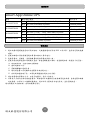
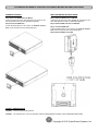
User’s Manual
OL1000RTXL2U
OL1500RTXL2U
OL2200RTXL2U
OL3000RTXL2U
CyberPower Systems Inc.
www.cpsww.com
K01-0000282-01
重要安全警語
本手冊包含重要的操作說明,應遵循安裝並維護 UPS 和電池。請仔細閱讀並遵守所有的安裝指引與
警示。安裝前需仔細閱讀本手冊再進行安裝與操作。
注意! UPS 須接到具地線的電源插座,並有保險絲或斷路器等過電流保護器。
注意! 如需關閉連接到 UPS 的設備時,請先關閉 UPS 電源再拔掉插頭。
注意! 不得使用在醫療或生命維護設備! CyberPower 並不銷售產品在生命維護或醫療應用上,
任何影響生命維護、醫療應用或病人護理等皆不得使用。
注意! 在 UPS 電池模式下,電池接頭斷開可以切斷危險的帶電元件。
注意! 為了防止火災或觸電危險,UPS 需安裝在溫度和濕度合理控制下的室內環境。
(請參閱規格
可接受的溫度和濕度範圍)。
注意! 為了減少觸電危險,勿取下上蓋。除電池可替換外,內部無其他可供使用者維修的零件。
注意! 為了避免觸電危險,在更換電池或作為電腦設備備用電源前,請先關閉 UPS 電源開關。
注意! 不得使用在水族箱或相關水源設備上!為降低發生火災的風險,任何有潛在水源處皆不得
使用,如壓縮機冷凝水會導致機器短路起火。
注意! 交流輸出電纜使用長度不得超過 10 米。
注意! 電池有可能會產生相當大的短路電流,所以在對電池進行更換或維修時,請務必採取以下
措施,並由經授權的合格專業人員進行維護。
1. 取下身上的手表、戒指、項鍊或其他金屬物品。
2. 使用具有絕緣握把的工具。
注意! UPS 電池可產生能源。在 UPS 的輸入沒有連接至交流電源時,其輸出插座可能帶有電壓。
注意! UPS 開啟時,請勿拔下輸入線。這會使 UPS 及其連接設備的安全接地失效。
注意! 為了防止觸電,在安裝輸入線及輸出線時,請先關閉交流電源及 UPS。並請優先配接安全
接地的部分。
注意! 為了防止火災,在安裝輸入線及輸出線時,請使用正確尺寸的電源線。並由經授權的合格
專業人員安裝。
注意!
注意!
注意!
注意!
為了防止爆炸,請勿將電池丟入火中。
不要打開或毀壞電池,釋出的電解液對皮膚和眼睛是有害的。
不要阻塞 UPS 前後左右的外殼通風口。
不要連接家用電器如吹風機到 UPS 的輸出插座。
警告使用者
這是甲類的產品,在住宅環境中,此一產品可能會造成無線電干擾,在此情況下,使用者可能會被
要求採取額外的處置。
I
碩天科技股份有限公司
規格說明
Smart App Online UPS
型號
OL1000RTXL2U
OL1500RTXL2U
OL2200RTXL2U
OL3000RTXL2U
額定電壓/電流
最大功率
輸入
AC 120V(+6%/-10%), 8.4A MAX, 50/60Hz
--
輸出
AC 120V, 8.4A MAX, 50/60Hz
AC 120V (+6%/-10%), 12.5A MAX, 50/60Hz
1000VA/900W
AC 120V, 12.5A MAX, 50/60Hz
AC 120V (+6%/-10%), 18.4A MAX, 50/60Hz
1500VA/1350W
2200VA/1800W
輸入
AC 120V, 18.4A MAX, 50/60Hz
AC 120V (+6%/-10%), 25.0A MAX, 50/60Hz
輸出
AC 120V, 25.0A MAX, 50/60Hz
3000VA/2700W
輸入
輸出
輸入
輸出
----
電池安全
1. 電池的壽命隨環境溫度的升高而縮短。定期更換電池可保證 UPS 工作正常,並保證足夠的後備
時間。
2. 蓄電池維護必須由具備蓄電池專業知識的人員來進行。
3. 更換蓄電池,其類型、型號與數量均應與原電池保持一致。
4. 蓄電池存在電擊危險和短路電流危險。為避免觸電傷人事故,在更換電池時,請遵守下列警告:
A. 請勿佩帶手錶、戒指或類似金屬物體。
B. 使用絕緣的工具。
C. 穿戴橡膠鞋和絕緣手套。
D. 請勿將金屬工具或類似的金屬零件放在電池上。
E. 在拆電池連接端子前,必須先斷開連接在電池上的負載。
5. 請勿將蓄電池暴露於火中,以免引起爆炸,危及人身安全。
6. 非專業人士請勿打開或損毀蓄電池,因為電池中的電解液含有強酸等危險物質,會對皮膚和眼睛
造成傷害。如果不小心接觸到電解液,應立即用大量的清水進行清洗,並去醫院檢查。
請勿將電池正負極短路,會導致電擊或著火
碩天科技股份有限公司
II
IMPORTANT SAFETY INSTRUCTIONS
This manual contains important instructions. Please read and follow all instructions carefully during installation and operation of the unit. Read this manual
thoroughly before attempting to unpack, install, or operate the UPS.
CAUTION! The UPS must be connected to a grounded AC power
outlet with fuse or circuit breaker protection. DO NOT plug the UPS into
an outlet that is not grounded. If you need to power-drain this equipment,
turn off and unplug the unit.
CAUTION! Wiring must be done by qualified personnel.
CAUTION! DO NOT USE FOR MEDICAL OR LIFE SUPPORT
EQUIPMENT! Under no circumstances this unit should be used for
medical applications involving life support equipment and/or patient care.
CAUTION! The battery can power hazardous components inside the
unit, even when the AC input power is disconnected.
CAUTION! DO NOT USE WITH OR NEAR AQUARIUMS! To reduce
the risk of fire, do not use with or near aquariums. Condensation from
the aquarium can come in contact with metal electrical contacts and
cause the machine to short out.
CAUTION! The UPS should be placed near the connected equipment
and easily accessible.
CAUTION! To prevent the risk of fire or electric shock, install in a
temperature and humidity controlled indoor area, free of conductive
contaminants. (Please see specifications for acceptable temperature and
humidity range).
CAUTION! Do not dispose of batteries in fire as the battery may
explode.
CAUTION! Do not open or mutilate the battery, released electrolyte is
harmful to the skin and eyes.
CAUTION! (No User Serviceable Parts): Risk of electric shock, do
not remove cover. No user serviceable parts inside. Refer servicing to
qualified service personnel.
CAUTION! A battery can present a risk of electric shock and high short
circuit current. The following precaution should be observed when
working on batteries
1. Remove watches, rings or other metal objects.
2. Use tools with insulated handles.
CAUTION! (Non-Isolated Battery Supply): Risk of electric shock,
battery circuit is not isolated from AC power source; hazardous voltage
may exist between battery terminals and ground. Test before touching.
CAUTION! The unit has a dangerous amount of voltage. When the
UPS indicators is on, the units may continue to supply power thus the
unit’s outlets may have a dangerous amount of voltage even when it’s not
plugged in to the wall outlet.
CAUTION! To reduce the risk of fire, connect the UPS to a branch
circuit with 12 amperes (OL1000) / 15 amperes (OL1500) / 20 amperes
(OL2200) / 30 amperes (OL3000) maximum over-current protection in
accordance with the National Electric Code, ANSI/NFPA 70.
CAUTION! Make sure everything is turned off and disconnected
completely before conducting any maintenance, repairs or shipment.
CAUTION! The AC outlet where the UPS is connected should be close
to the unit and easily accessible.
CAUTION! Connect the Protection Earth (PE) safety conductor before
any other cables are connected.
CAUTION! Please use only UL-marked mains cable, (e.g. the mains
cable of your equipment), to connect the UPS to the AC outlet.
WARNING! (Fuses): To reduce the risk of fire, replace only with the
same type and rating of fuse.
CAUTION! Please use only UL-marked power cables to connect any
equipment to the UPS.
CAUTION! When installing the equipment, ensure that the sum of the
leakage current of the UPS and the connected equipment does not
exceed 3.5mA.
DO NOT INSTALL THE UPS WHERE IT WOULD BE EXPOSED TO
DIRECT SUNLIGHT OR NEAR A STRONG HEAT SOURCE!
CAUTION! The OL1000 / OL1500 / OL2200 / OL3000 models may
only be installed by qualified maintenance personnel..
DO NOT BLOCK OFF VENTILATION OPENINGS AROUND THE
HOUSING!
CAUTION! Do not unplug the unit from AC Power during operation, as
this will invalidate the protective ground insulation.
DO NOT CONNECT DOMESTIC APPLIANCES SUCH AS HAIR
DRYERS TO UPS OUTPUT SOCKETS!
CAUTION! To avoid electric shock, turn off and unplug the unit before
installing the input/output power cord with a ground wire. Connect the
ground wire prior to connecting the line wires!
SERVICING OF BATTERIES SHOULD BE PERFORMED OR
SUPERVISED BY PERSONNEL KNOWLEDGE OF BATTERIES AND
THE REQUIRED PRECAUTIONS. KEEP UNAUTHORIZED
PERSONNEL AWAY FROM BATTERIES!
CAUTION! Do not use an improper size power cord as it may cause
damage to your equipment and cause fire hazards.
1
Copyright © 2012 CyberPower Systems, Inc.
UNPACKING
Phone line
USB communication cable
Serial Interface Cable (RS-232)
1K/1.5KVA or 2.2K/3KVA UPS
Flat head screws: M5X8L (8)
Pan head screws: M5X12L (12)
User’s manual
Register card
Plastic washers (8)
Rackmount left rail
Rackmount right rail
(Optional)
Screw hole dust covers (10)
PowerPanel® Business Edition software CD
Rackmount ears (Stands) (2)
2
Copyright © 2012 CyberPower Systems, Inc.
HARDWARE INSTALLATION
HARDWARE INSTALLATION
Step 3: Adjust rackmount rails to fit your rack
These versatile UPS systems can be mounted in a rackmount or vertical
tower orientation. This versatility is especially important to growing
organizations with changing needs that value having the option to
position a UPS on a floor or in a rackmount system. Please follow the
instructions below for the respective mounting methods.
Attach the rackmount rail to your rack with two M5X12L screws and two
plastic washers at the front of the rack. (Located in position 1 & position 6)
Do not tighten the screws. Adjust the rail size on the rail assembly of your
rack. Secure the rail to the rear of the rack with two M5X12L screws and
two plastic washers. Tighten all screws at the front and rear of the rail.
Once completed, perform the same steps for assembling the other
rackmount rail.
SAFETY PRECAUTIONS
CAUTION! To prevent the risk of fire or electric shock, only use the
supplied hardware to attach the mounting brackets.
RACKMOUNT INSTALLATION
Step 1: Rackmount ears installation
Attach the two rackmount ears to the UPS using the provided screws
M5X8L*8pcs.
Place the UPS on a flat stable surface with the front of the unit facing
toward you. Secure the UPS to your rack with four M5X12L screws at the
front of the rack. (Located in position 2 & position 5)
Step 2: Rackmount rail Installation
The rails adjust to mount in 48-cm (19-inch) panel racks from 52 to
91.5cm (20.5 to 36 inches) deep. Select the proper holes in the rack for
positioning the UPS in the rack. The UPS takes up position 1 through
position 6.
3
Copyright © 2012 CyberPower Systems, Inc.
HARDWARE INSTALLATION
ELECTRICAL INSTALLATION
After completing the hardware installation of the UPS, you are now ready to plug in the UPS and connect your equipment.
SAFETY PRECAUTIONS
CAUTION! Installation environment should be in a temperature and humidity controlled indoor area free of conductive contaminants. Do not install this UPS
where excessive moisture or heat is present (Please see specifications for acceptable temperature and humidity range).
CAUTION! Never install a UPS, or associated wiring or equipment, during a lightning storm.
CAUTION! Do not work alone under hazardous conditions.
CAUTION! In case of the risk of electric shock, do not remove the top cover.
CAUTION! The battery can energize hazardous live parts inside even when the AC input power is disconnected.
4
Copyright © 2012 CyberPower Systems, Inc.
INSTALLING YOUR UPS SYSTEM
SYSTEM BLOCK DIAGRAM
Bypass
Input
Input
Filter
PFC
AC/DC
BUS
Charger
AC/DC
Battery
DC/DC
Inverter
DC/AC
INV
RY
Control
&
Monitoring
Output
Filter
Output
LCD Module
USB & DB9
SNMP Slot
Line Mode
Battery Mode
Bypass Mode
HARDWARE INSTALLATION GUIDE
1. Battery charge loss may occur during shipping and storage. Before
6. This UPS is equipped with an auto-charge feature. When the UPS is
using the UPS, it’s strongly recommended to charge batteries for four
hours to ensure the batteries’ maximum charge capacity. To recharge the
batteries, simply plug the UPS into an AC outlet.
plugged into an AC outlet, the battery will automatically charge, even
when the unit is switched off.
2. When using the included software, connect either the serial or the
AC outlet at all times.
7. To maintain an optimal battery charge, leave the UPS plugged into an
USB cable between the computer and the corresponding port on the UPS.
Note: If the USB port is used, the serial port will be disabled. They cannot
be used simultaneously. After connecting to either the USB port or the
Serial port on the UPS, a computer with the PowerPanel® Business
Edition Agent software installed can control the operating schedule,
battery test, outlets, as well as obtain UPS status information. However,
other computers with PowerPanel® Business Edition Client software can
only obtain UPS status information via LAN connection.
8. Before storing the UPS for an extended period of time, turn the unit
OFF. Then cover it and store it with the batteries fully charged. Recharge
the batteries every three months to ensure good battery capacity and
long battery life. Maintaining a good battery charge will help prevent
possible damage to the unit from battery leakage.
9. The UPS has one USB port (default) and one Serial port that allows
storage device (Hard drive, Tape drive, etc.) into the outlets only when
the UPS is off and unplugged. DO NOT plug a laser printer, copier, space
heater, vacuum, paper shredder or other large electrical device into the
UPS. The power demands of these devices will overload and possibly
damage the unit.
connection and communication between the UPS and any attached
computer running the PowerPanel® Business Edition Agent software. The
UPS can control the computer’s shutdown during a power outage
through the connection while the computer can monitor the UPS and alter
various programmable parameters. Note: Only one communication port
can be used at a time. The port not in use will automatically become
disabled or the serial port will be disabled if both ports are attached.
4. To protect a fax machine, telephone, modem line or network cable,
10. EPO (Emergency Power Off) Port:
connect the telephone or network cable from the wall jack outlet to the
jack marked “IN” on the UPS and connect a telephone cable or network
cable from the jack marked “OUT” on the UPS to the modem, computer,
telephone, fax machine, or network device.
EPO ports allow administrators the capability to connect the UPS unit to
customer-supplied EPO switches. These installations give operators a
single access point to immediately power-off all equipment connected to
the UPS during an emergency.
5. Press the ON/OFF switch to turn the UPS on. The Power-On indicator
11. To avoid electric shock, turn the unit OFF and disconnect the unit
light will display when activated. If an overload is detected, an audible
alarm will sound and the UPS will continuously emit two beeps per
second. For resetting the unit, unplug some equipment from the outlets.
Make sure your equipment carries a load current within the unit’s safe
range, (refer to the technical specifications).
from utility power before hardwiring the UPS (in/out power cord). The
in/out power cord MUST be grounded.
3. Connect your computer, monitor, and any externally-powered data
5
Copyright © 2012 CyberPower Systems, Inc.
BASIC OPERATION
POWER MODULE FRONT/REAR PANEL DESCRIPTION
1. Power Button / Power on Indicator
Master ON/OFF for the UPS. Indicates that the UPS is on
and supplying power.
2. UPS Status / Fault / Replace Battery LED Indicator
Indicates the status of the UPS, displaying whether it is
operating in Line, Battery or Bypass Mode, if it has an
internal fault or if the battery needs to be replaced.
3. Multifunction LCD Readout
Shows UPS status, information, settings and events.
4. Function Buttons
Scroll up, scroll down, select and cancel LCD menu.
OL1000RTXL2U / OL1500RTXL2U / OL2200RTXL2U / OL3000RTXL2U
5. Input Circuit Breaker
Provides input overload and fault protection.
6. Battery Backup & Surge Protected Outlets
Provides battery backup and surge protection. They
ensure power is provided to connected equipment over a
period of time during a power failure.
Critical / Noncritical Load
Allows the creation of load priorities to ensure that battery
power reserves are transferred to specified outlets during
a power outage. The unit can be programmed to provide
additional runtime for equipment connected to the
“CRITICAL” outlets, while stopping the power supply to
equipment connected to “NONCRITICAL” outlets after a
designated period of time.
OL1000RTXL2U / OL1500RTXL2U
7. Serial Port
Serial port provides communication between the UPS and
the computer. The UPS can control the computer’s
shutdown during a power outage through the connection
while the computer can monitor the UPS and alter its
various programmable parameters.
OL2200RTXL2U
8. USB port
This is a connectivity port which allows communication
and control between the UPS and the connected computer.
It is recommended to install the PowerPanel® Business
Edition Agent software on the PC/Server connected with
the USB cord.
9. Surge Protected Communication Ports RJ-45/RJ-11
These ports are used to protect standard RJ-45/RJ-11
based products (ADSL, LAN, Phone/ Modem-Lines) and
cabling systems from surges.
10. Relay Output Connector
Convert UPS signals into real potential-free Dry Contacts
for industrial control.
11. SNMP/HTTP Network slot
Slot to install the optional SNMP card for remote network
control and monitoring.
OL3000ERTXL2U
13. EPO (Emergency Power Off) Connector
Enables an emergency UPS Power-Off from a remote location.
14. AC Input Inlet
Connect the AC Power cord to a properly wired and grounded outlet.
6
Copyright © 2012 CyberPower Systems, Inc.
OPERATION INSTRUCTIONS FOR LCD MODULE
LED INDICATORS – UPS STATUS
LED Indicators
Color
UPS Status Description
ON/OFF
White
UPS power is on.
ON-LINE
Green
UPS is operating in Line Mode.
BATTERY ON
Yellow
UPS is operating in Battery Mode.
BYPASS
Yellow
UPS is operating in Bypass Mode, Manual Bypass or ECO (Economy) Mode.
FAULT
Red
UPS has an internal fault. See “Trouble Shooting” for additional information.
REPLACE BATTERY
Red
Battery will soon need to be replaced due to insufficient runtime.
LCD SCREEN – UPS STATUS
LCD Screen
UPS Status Description
Line Mode
UPS is operating in Line Mode.
Battery Mode
UPS is operating in Battery Mode.
Bypass Mode
UPS is operating in Bypass Mode.
Manual Bypass
UPS is operating in Manual Bypass.
ECO Mode
UPS is operating in ECO (Economy) Mode.
BUTTON OPERATION
Button
Operation Description
ON/OFF
Press this button to turn on or turn off UPS.
▲
Press this button to scroll up in the LCD menu.
▼
Press this button to scroll down in the LCD menu.
ENTER
Press this button to select an option.
ESC
Press this button to cancel or return to previous LCD menu.
7
Copyright © 2012 CyberPower Systems, Inc.
LCD SETUP FUNCTIONS
MULTI-FUNCTION LCD MAIN MENU
Press “Enter” button to activate “MAIN MENU”.
MAIN MENU submenu
Function Description
Information
Displays the UPS information.
Configure
Displays the UPS settings that can be configured by the user.
Event Log
Displays the 3 most recent events,
(day/hour/minute), and event description.
by
event
count,
time
LCD INFORMATION READOUT
There are 19 types of UPS information available for display.
1.
Press the “ENTER” button to activate the “MAIN MENU”.
2.
Press the “▲” and “▼” buttons to scroll to the “Information” option.
3.
Press the “ENTER” button to select the “Information” submenu.
4.
Press the “▲” and “▼” buttons to scroll through the “Information” submenu in the following table.
5.
Press the “ESC” button to return to UPS Status.
Information Submenu
Description
O/P Volt
= XXX.XV
Displays the Output Voltage
O/P Freq
= XX.XHz
Displays the Output Frequency
I/P Volt
= XXX.XV
Displays the Input Voltage
I/P Freq
= XX.XHz
Displays the Input Frequency
O/P Load =
XXX%
X.XA
Displays the Output Load as a Percentage of Maximum load
O/P Amp
=
O/P Watt
=XXXXXW
Displays the Output Wattage
O/P VA
=XXXXXVA
Displays the Output VA
BAT Volt
= XXX.XV
Displays the Battery Voltage
BAT Cap
=
Displays the Estimated Percentage of Battery Capacity
XXX%
Displays the Output Current
BAT Runtime =XXXM
Displays the Estimated Battery Runtime in Minutes
EBM Number =
Displays the External Battery Module Number
X
Displays the Approximate inside Temperature in both ℃ (Celsius) and ℉
TEMP =XX°C / XXX°F
SBM
Rating
=
XXXXX
= XXK VA
MCU Ver =
XXXX
(Fahrenheit) for the UPS
Displays the Stage of Smart Battery Management
Displays the UPS Rating
Displays the MCU Firmware Version
Model Name
Displays the UPS Model Name
Date & Time
- - - - / - - / - - - -:- -
Displays the present Date & Time
Next BAT Change
XXX / XXXX
Displays the next Battery Change Date & Time
8
Copyright © 2012 CyberPower Systems, Inc.
LCD SETUP FUNCTIONS
LCD EVENT LOG
3 Event Logs of UPS can be recorded.
1.
Press the “ENTER” button to activate the “MAIN MENU”.
2.
Press the “▲” and “▼” buttons to scroll to the “Event Log” option.
3.
Press the “ENTER” button to select the “Event Log” submenu.
4.
Press the “▲” and “▼” buttons to scroll through the “Event Log” submenu in the following table.
5.
Press the “ESC” button to return to UPS Status.
Event Log Submenu
Description
XXDXXHXXM (without PowerPanel® Business or RMCARD302)
(X)
--/--
- -:- - (with PowerPanel® Business or RMCARD302)
Event Content
MULTI-LANGUAGE INTERFACE
Users can configure 1 of the 4 available languages for display.
([English], [Españ ol-Spanish], [Français-French], [Deutsch-German])
1.
Press the “ENTER” button to activate the “MAIN MENU”.
2.
Press the “▲” and “▼” buttons to scroll to the “Configure” option.
3.
Press the “ENTER” button to select the “Configure” submenu.
4.
Press the “▲” and “▼” buttons to scroll through the “Language” options.
5.
Press the “ENTER” button to select the “Language” submenu.
6.
Press the “▲” and “▼” buttons to scroll to the language that you want to select.
You may be prompted to save the selection, if so press the “ENTER” button to save the setting.
7.
Press the “ESC” button to cancel or return to previous LCD menu.
LCD SETTINGS CONFIGURATION
There are 21 UPS settings that can be configured by the user.
1.
Press the “ENTER” button to activate the “MAIN MENU”.
2.
Press the “▲” and “▼” buttons to scroll to the “Configure” option.
3.
Press the “ENTER” button to select the “Configure” submenu.
4.
Press the “▲” and “▼” buttons to scroll to the “Configure” submenu in the following table.
5.
Press the “ENTER” button to select the setting you want to configure.
The first configuration parameter will be displayed on the second column of LCD screen.
6.
Press the “▲” and “▼” buttons to scroll through the different parameters.
7.
Press the “ENTER” button to select the parameter you want to change.
You may be prompted to save the selection, if so press the “ENTER” button to save the setting. Some options are saved
and started automatically. (See the following table for additional details.)
8.
Press the “ESC” button to cancel or return to the previous LCD menu.
9
Copyright © 2012 CyberPower Systems, Inc.
LCD SETUP FUNCTIONS
Configure Submenu
Available Settings
Default Setting
Output Voltage*
= [100V] [110V] [115V] [120V] [127V]
120V
Range= [+/- 1%] [+/- 2%] [+/- 3%] [+/- 4%] [+/- 5%]
Sync Freq Window
+/- 5%
[+/- 6%] [+/- 7%] [+/- 8%] [+/- 9%] [+/-10%]
Range= [+10%/-10%] [+10%/-15%] [+10%/-20%]
Bypass V Window
Bypass Condition
+10%/-15%
[+15%/-10%] [+15%/-15%] [+15%/-20%]
[Check Freq/Volt] [Check Volt Only] [No Bypass]
Check Freq/Volt
[Disable] [Enable]
Disable
ECO Mode**
[V Range= +/-15%] [V Range= +/-10%]
(for [Enable])
V Range= +/-10%
Manual Bypass
[Disable] [Enable]
Disable
Battery Test
[Activate?]
None
Audible Alarms
[Disable] [Enable]
Enable
EBM Number
= [0] [1] [2] [3] [4] [5] [6] [7] [8] [9] [10]
0
Wiring Fault
[Disable] [Enable]
Disable
NCL Control
[Outlet On] [Outlet Off]
Outlet On
Language
[English] [Español-Spanish] [Français-French] [Deutsch-German]
English
Generator Mode***
[Disable] [Enable]
Disable
Communication
[Disable] [Enable]
Enable
[I/P Power Fail] [Battery Low] [Summary Alarm]
Dry Relay Set
I/P Power Fail
[UPS On Bypass] [UPS Fail]
Converter Mode****
[Converter Off] [O/P Freq = 50Hz] [O/P Freq = 60Hz]
Converter OFF
Screen Saver
[Disable] [1 Minutes] [5 Minutes]
5 minutes
Clear Event Log
[Activate?]
None
Button OFF LOCK
[Disable] [Enable]
Disable
Charger Function
[SBM] [Constant]
SBM
Signal Inputs
[Disable] [EPO] [ROO]
Disable
*) 100V are derated by 20%, 110 V are derated by 10%
**) This function can’t be set when Manual Bypass, Generator Mode or Converter Mode is enabled.
***) UPS has no bypass when Generator Mode is enabled.
****) UPS has no bypass when Converter Mode is enabled. This function can only be set before the UPS is on.
SILENCING AUDIBLE ALARMS
1.
Press any of four function buttons on the LCD module; Note: the alarm can not be turned off for a “Battery Low”
condition. This condition will still result in an audible alarm.
2.
Change the 'Audible Alarms' option to 'Disabled' in the LCD screen and it will no long give an audible alarm for any
malfunction.
MANUAL BATTERY TEST
Select 'Active' in the 'Battery Test' portion of the LCD screen and the unit will perform a manual battery test.
10
Copyright © 2012 CyberPower Systems, Inc.
LCD MODULE REMOTE CONTROL and WALL-MOUNTING INSTRUCTIONS
REMOTE CONTROL
WALL-MOUNTING INSTRUCTIONS
Step 1: Remove the Multifunction LCD Module
Step 1: Remove the Multifunction LCD Module
Unscrew the right panel of the UPS. Separate the right panel from the
UPS. Gently lift the LCD module out. Reinstall the right panel.
Unscrew the right panel of the UPS. Separate the right panel from the
UPS. Gently lift the LCD module out. Reinstall the right panel.
Step 2: Connect the DB26 Cable
Step 2: Rotate the DB26 Connector of LCD Module
Connect the DB26 cable from LCD module to the “Remote Control
Port” on the front panel as shown in the following figure.
Step 3: Connect the DB26 Cable
Connect the DB26 cable from LCD module to the “Remote Control
Port” on the front panel as shown in the following figure.
Step 4: Mount LCD Module on the Wall
SAFETY PRECAUTIONS
CAUTION! It must be done by qualified personnel.
CAUTION! To avoid electric shock, turn off and unplug the unit before installing REMOTE CONTROL or WALL-MOUNTING INSTRUCTIONS.
11
Copyright © 2012 CyberPower Systems, Inc.
MAINTENANCE
CAUTION! Do not open or mutilate the batteries. Electrolyte fluid is
harmful to the skin/eyes and may be toxic.
CAUTION! To avoid electric shock, turn off and unplug the UPS from
the wall receptacle before servicing the battery.
CAUTION! Only use tools with insulated handles. Do not lay tools or
metal parts on top of the UPS or battery terminals.
Storage
To store your UPS for an extended period, cover it and store with the
battery fully charged. Recharge the battery every three months to ensure
battery life.
Battery Replacement
Please read and follow the Safety Instructions before servicing the
battery. Battery replacement should be performed by trained personnel
who are familiar with the procedures and safety precautions. Make a note
of the replacement Battery tray number.
Replacement Batteries
Please refer to the front side of the UPS for the model number of the
correct replacement batteries. For battery procurement, log onto
www.CPSww.com, or contact your local dealer.
Safety Precautions
Battery Disposal
CAUTION! Only use replacement batteries which are certified by
CyberPower Systems. Use of incorrect battery type is an electrical
hazard that could lead to explosion, fire, electric shock, or short circuit.
CAUTION! Batteries contain an electrical charge that can cause
severe burns. Before servicing batteries, please remove any conductive
materials such as jewelry, chains, wrist watches, and rings.
Batteries are considered hazardous waste and must be disposed of
properly. Contact your local government for more information about
proper disposal and recycling of batteries. Do not dispose of batteries
in fire.
Battery Installation
Step 1: Remove the front panels
Step 2: Remove the retaining screws from
the cable protection cover and then remove
the cover itself
Step 3: Unscrew the connectors fixed plates
on the battery retaining cover
Step 4: Pull the battery tray out slowly and
then put the new battery tray back into the
compartment
Step 5: Fasten back the connectors on the
battery retaining cover. Then insert the
battery connectors and tighten the screws
of battery retaining cover
Step 6: Install the front panels
12
Copyright © 2012 CyberPower Systems, Inc.
TECHNICAL SPECIFICATIONS
Model
Configuration
Capacity (VA)
Capacity (Watts)
Form Factor
Energy-saving Technology
Input
Input Voltage Range
Input Frequency Range
Input Power Factor
Cold Start
Output
Output Waveform
Output Voltage*
Output Frequency
Transfer Time (Typically)
Rated Power Factor
Harmonic Distortion
Crest Factor
ECO Mode Voltage Regulation
UPS Outlets
Protection
Surge Protection
Phone / Network Protection
Overload Protection
Short Circuit Protection
Battery
Specifications
Recharge Time (Typically)
Sealed, Maintenance Free
Hot-Swappable
Status Indicators
LCD Screen
LED Indicators
Audible Alarms
Environment
Operating Temperature
Operating Relative Humidity
Management
On-Device Features
Connectivity Ports
SNMP/HTTP Capable
Software
Power Management Software
Physical
OL1000RTXL2U
1000VA
900W
OL1500RTXL2U
OL2200RTXL2U
OL3000RTXL2U
1500VA
2200VA
1350W
1800W
Rackmount / Tower
Yes, ECO Mode Efficiency > 93%
3000VA
2700W
120Vac
50 / 60Hz
0.99
Yes
Sine wave
120Vac ±2%
50 / 60Hz (Auto-Sensing or Configurable) ±0.25Hz
0ms
0.9
0.82
0.9
THD < 3% at Linear Load, < 5% at Non-linear Load
3:1
±10%, ±15% (Configurable)
(6) NEMA 5-20R,
(6) NEMA 5-20R,
(8) NEMA 5-15R
(1) L5-20R
(1) L5-30R
IEC 61000-4-5 Level 3
RJ11/RJ45 (One In/One Out)
Line Mode:
105~125% Load for 1 min,
126~150% Load for 10 sec
Battery Mode: 105~130% Load for 10 sec, 131~150% Load for 2 sec
UPS Output Cut off Immediately or Input Fuse / Circuit Breaker Protection
(3) 12V/9AH
(6) 12V/9AH
4 hours
Yes
Yes
Multi-Function LCD Readout that Supports:
Multi-Language Interface,
(19) Types of Read Out,
(21) Types of Function Setting, (3) Event Logs
Power On (White),
Line Mode (Green),
Battery Mode (Yellow),
Bypass Mode (Yellow), Fault (Red),
Replace Battery (Red)
Battery Mode, Battery Low, Overload, UPS Fault, Replace Battery
32℉ to 104℉ ( 0℃ to 40℃)
0 to 90% Non-Condensing
Self Test, Auto-Charge, Auto-Restart, Auto-Overload Recovery
(1) Serial Port (RS232), (1) USB Port, (1) Relay Out
(1) Expansion Port (With optional SNMP card)
®
PowerPanel Business Edition
L x W x H = 16.9 x 17 x 3.5in.
Dimensions
(43 x 43.3 x 8.8cm)
Net Weight
39.6lbs(18Kg)
Safety
Conformance Approvals
CE, UL
*)100V are derated by 20%, 110 V / 115V are derated by 10%
L x W x H = 23.6 x 17 x 3.5in.
(60 x 43.3 x 8.8cm)
68.2lbs(31Kg)
13
Copyright © 2012 CyberPower Systems, Inc.
TROUBLE SHOOTING
Problem
Warning
O/P Overload
Load Over XXX%
Battery Mode
Possible Cause
Solution
Your equipment requires more power than the
UPS can provide. If the UPS is in Line Mode
then it will transfer to Bypass Mode; if the UPS is
in Battery Mode it will shutdown.
Your equipment requires more power than the
setting in the Power Management Software
®
(PowerPanel Business) will allow.
BAT Disconnected
Battery Failure
UPS has failed a Battery Test.
Replace Battery
EPO OFF
Wiring Fault
Line Abnormal
Battery will soon need to be replaced due to
insufficient runtime.
Missing the EPO connection.
Check battery connector and battery breaker.
1. Check battery connector and battery breaker.
2. Contact technical support to replace the
battery.
Contact technical support to replace the battery.
Check the EPO connection.
Exchange line and neutral wires.
Missing ground wire.
Connect ground wire.
No ground wire.
Wrong utility power backed up during UPS autorestart.
Disable Wiring Fault alarm on LCD panel.
Check whether voltage or frequency of utility
power is out of range.
Your attached equipment may have problems,
please remove them and check again.
Check the fan for operation and if the ventilation
hole has been covered.
Output short circuit.
Over Temperature
High ambient temperature.
Autorestart Lock
UPS will restart automatically when acceptable
utility power returns.
Line and neutral wires are reversed.
Output Short
Coldstart Lock
Shut off the non-essential equipment or increase
the level in the Power Management Software.
Save your data and perform a controlledshutdown.
UPS is operating on battery power.
UPS is operating on battery power and will be
shutting down soon due to extremely low battery
voltage.
Missing battery power.
Battery Low
Shut off non-essential equipment. If this solves
the overload problem, the UPS will transfer to
normal operation.
UPS is locked to prevent consuming battery
power during shipping.
“Automatic Restore” is disabled in Power
®
Management Software (PowerPanel Business)
Plug into utility power for first-time operation.
Press “ON/OFF“ button to turn on UPS
Fault
1. Remove battery connector and
charger voltage.
2. Contact CyberPower for repair.
Over Charge
Battery is overcharged.
Charger Failure
Charger has failed.
High O/P V
Output voltage is too high.
Low O/P V
Output voltage is too low.
Bus Fault
Internal DC bus voltage is too high or too low.
check
1. Shut down UPS and turn off input breaker.
2. Contact CyberPower for repair.
CyberPower Systems Inc.
www.cpsww.com
©
Entire contents copyright 2012 CyberPower Systems Inc., All rights reserved. Reproduction in whole or in part
®
®
without permission is prohibited. PowerPanel Business Edition and PowerPanel Personal Edition are trademarks of
CyberPower Systems Inc.
14
Copyright © 2012 CyberPower Systems, Inc.