1
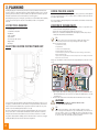
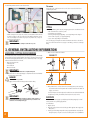
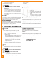
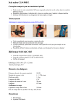
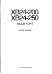
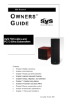
Piping
Installation
Instructions
for a central vacuum system
This Central Vacuum System has been
designed by Nuera Air and built with
specialised materials of the highest
quality.
It is therefore important to follow the
installation instructions in order to
benefit from all the advantages that your
new system provides.
EN
Table of Contents
Safety Rules����������������������������������������������������������������������������������������������������������������������������������������������������������������� 14
Fire protection���������������������������������������������������������������������������������������������������������������������������������������������������� 14
Safety Equipment������������������������������������������������������������������������������������������������������������������������������������������������� 14
Low Voltage Remote Control������������������������������������������������������������������������������������������������������������������������ 14
Inspection of Power Unit ������������������������������������������������������������������������������������������������������������������������������� 14
Planning���������������������������������������������������������������������������������������������������������������������������������������������������������������������� 15
List of Tools Required�������������������������������������������������������������������������������������������������������������������������������������� 15
Select the location for the Power Unit���������������������������������������������������������������������������������������������������� 15
Choose the hose length��������������������������������������������������������������������������������������������������������������������������������� 15
Location of Vacuum Inlets ��������������������������������������������������������������������������������������������������������������������������� 15
The garage
Piping����������������������������������������������������������������������������������������������������������������������������������������������������������������������� 16
General installation information���������������������������������������������������������������������������������������������������������������� 16
Measuring, cutting and assembling����������������������������������������������������������������������������������������������������������� 16
Adhesive ����������������������������������������������������������������������������������������������������������������������������������������������������������������� 16
Low voltage remote control ����������������������������������������������������������������������������������������������������������������������� 17
Jacketed low voltage wiring?
Common components of installation kits �������������������������������������������������������������������������������������������� 17
Other components available������������������������������������������������������������������������������������������������������������������������� 17
Is it necessary to insulate the piping network of a central vacuum system? �������������������������� 18
General Installation Procedures ����������������������������������������������������������������������������������������������������������������� 18
Installing a vacuum inlet������������������������������������������������������������������������������������������������������������������������������� 18
For a partition wall (if there is enough space inside the wall)
Additional information ������������������������������������������������������������������������������������������������������������������������������������� 19
Leak testing����������������������������������������������������������������������������������������������������������������������������������������������������������� 19
Cleaning and Maintenance���������������������������������������������������������������������������������������������������������������������������� 19
Service �������������������������������������������������������������������������������������������������������������������������������������������������������������������� 19
On the floor; Easy places for installation; For new construction; For homes with no
attic or on a concrete slab
13
EN
1. Safety Rules
Piping installation for a central vacuum system is not complicated. All that is required is to
have a few hand tools and to read the instructions carefully. However, it is essential to do
the installation carefully and safely. We recommend that you read the next few lines with
the greatest attention.
Inspection of Power Unit
The Power Unit and all connections should be inspected before starting and at regular
intervals to ensure normal, reliable and safe operation.
Warning!
Fire protection
Every installation must conform to local and/or provincial and/or federal building and
fire codes.
•  Be sure to take these codes into account when installing your system and hire a
plumber if you have any doubt about the procedures to obtain best performance from
your central system.
Take ownership of a central vacuum system only if it is in good condition;
safety of the equipment is compromised if it is damaged.
*
•
•
A defective central vacuum system must be disabled and disconnected from the electric
•
power source.
Repairs must be made by a qualified technician, and defective components must be
replaced exclusively with genuine Nuera Air parts.
Mortal danger!
Pay attention when working inside panels or walls that can hide or
contain water or gas pipes or electrical components!
Danger: fire and explosion!
*
Safety Equipment
To prepare walls or drill holes in floors, be sure to wear recommended safety equipment
such as a hard hat, work gloves and safety glasses.
•  Please ensure that the stability and solidity of a wall is not compromised by creating
holes and openings for piping to pass through.
•  All holes and openings must be properly cut and de-burred.
•  If the piping must cross a firewall, appropriate regulatory safety measures must be
taken. In a firewall, piping and vacuum inlets must usually be made of metal. The
foundation must not be compromised when installing the piping network. Consult the
building code for your region.
NEVER VACUUM UP:
•  Liquids (unless specified)
•  Explosive materials
•  Solvents (paint or other)
•  Gasoline, fuel, diesel
•  Combustible materials
•
Low Voltage Remote Control
Mortal danger!
Low voltage is only supplied when voltage is supplied to the power
unit. Low voltage remote control wiring must never come into contact
with another power source.
*
Note
»»an electrician’s help is recommended but not required
when working with the low voltage control lines.
14
EN
Risk of injury
•
•
Be careful when handling in a traffic area; passersby may trip over the hose.
Roll up the hose when moving it.
*
Never leave the hose connected while unattended.
Warning!
Ignoring safety rules risks creating a hazard to your health and to
those around you!
*
2. Planning
Installing the piping for a central vacuum system does not require specialized tools and can be done
by anyone. However, it is important to take time to plan the installation carefully. Be sure to check the
positioning of inlets several times, in relation to furniture, the length of the hose and the components
that will be inside the wall. You do not want to drill holes in the wrong places!
By following the tips we give you in this guide, you will have a successful installation while simplifying
your life. If you do not feel up to the task, we recommend that you make use of a specialized
technician.
List of Tools Required
Drill with 1/2» chuck
•  2-1/2» hole saw
•  Serrated knife or utility knife
•  Tape Measure
•  Philips screwdriver
•  Flat screwdriver
•  Electrician’s tape and connectors
•  Diagonal cutters
•  Wire hanger
•
Select the location for the Power Unit
Choose the hose length
Plan to use a 28’/8.5m hose to ensure optimal performance of the system. If a hose of this length will
not let you reach remote points, you can use a 34’/10.4m hose or install more than one vacuum inlet.
(see Location of Vacuum Inlets)
If you are renovating an existing building and you cannot install the desired number of vacuum inlets,
choose a 34’/10.4m hose.
Location of Vacuum Inlets
You will use your central vacuum system several times a week. Therefore it is important to choose
vacuum inlet locations strategically and ergonomically.
•  Vacuum inlets can be installed at any height that suits your preferences.
•  However, it is recommended to install them at the same height as electrical outlets, or about
16in/40cm to 24in/61cm above the finished floor.
•
TIP
»»Never install a vacuum inlet behind a door. Not only is this
inconvenient, but the hose may damage the door edges.
•
Here are some items to consider:
a. possible furniture locations;
b. high traffic areas;
c. location of electric baseboard heaters;
d. aesthetic appearance of the inlet location;
e. vacuum inlets are very useful near to areas that require frequent cleaning, such as the kitchen,
dining room and entrance hall.
f. If you use an accessory that requires an electrical outlet (such as an electric brush), the vacuum inlet
must be near to an electrical outlet.
To begin, you can evaluate the location of vacuum outlets using a drawing of your house at a scale of
1:100.
1. using a compass, draw circles on the drawing by placing the centers of these circles in the corners
which are furthest from the center of your home. For example, for a 28ft (8.5m) hose, use radii
of 3.3in (8.5cm);
2. the future location of the vacuum inlet should be inside the location where the circles overlap.
Select a location for the Power Unit which is away from the most frequented places in the house, such
as a garage - you want to hide the noise of the motor as much as possible. However, the Power Unit
must be located in a well ventilated location, especially if in a small room. If this is the case, ensure
that the room is well ventilated (install louvered doors or a vent).
Also select a location that is easily accessible for equipment maintenance. If the house has several
floors, for best results it is recommended to install the Power Unit in the basement or a lower floor.
Finally, the Power Unit must not be installed near a source of heat such as a furnace or in an attic.
If you plan to exhaust outside the building, install it on the exterior wall. For convenience, we suggest
installing the muffler, if the Power Unit does not have an integrated one.
15
EN
CAUTION!
*
*
if two circles don’t overlap, you need more than one outlet!
you must take stairs into account!
TIP
»»if the area of a floor is more than 1400ft² (130m²) or if the
floor is longer than 50ft(15.2m) you will definitely need at least 2
vacuum outlets. (if you use a 28ft(8.5m) hose). Depending on the
area to be cleaned and most suitable hose length, between 1 and
3 vacuum inlets are normally required per floor.
Use the following method to check the location of vacuum inlets:
The garage
If structurally possible, install a vacuum inlet close to the door to increase the reach of the hose
outside during the summer.
Piping
•
Simulate cleaning each room using the hose. To do this, ask an assistant to hold the end of the
hose at the point where you have assessed the inlet location. Walk around with it to cover the
entire area, including the corners at the ceiling. If you do not yet have the hose, cut a piece of
string the same length as the hose.
IMPORTANT!
*
Don’t forget to simulate cleaning the stairs and every room!
Before starting installation, plan the trajectory of the piping system to be the most effective. To do this:
•  make sure that the ducts are as direct as possible
•  avoid installing unnecessary fittings
•  avoid using short right angle (90 deg) fittings - use 45 degree fittings to make changes in
direction. If this is impossible, use long right angle fittings.
•  only use short 90 degree fittings for inlet installation
First, locate the piping connecting the Power Unit to the furthest vacuum inlet. This is the main line.
Then connect other inlets to this main line using long-T or 45-Y fittings, or with a series of 45 degree
fittings.
3. General installation information
Measuring, cutting and assembling
For all measurements, include an overlap of 3/4 in. (19 mm) for piping and fittings. Start assembly
from the furthest vacuum inlet and work towards the Power Unit. It is important to measure and trial
fit each branch before applying adhesive! When you are sure that the dry assembly is correct, apply
adhesive to this branch and move on to the next.
1. Always cut piping at 90° with:
•  A Nuera pipe cutter
•  Electric radial saw
•  Miter box & hack saw
IMPORTANT!
*
Only use a saw with a blade that is compatible with plastic.
4. Make connections in the direction of airflow.
Correct
Incorrect
2. Always de-burr all cuts - medium grit sandpaper or a utility knife works well. This will facilitate
connecting and give optimal air flow.
Danger
*  Take care not to cut yourself!
3. Always apply solvent around the end of the pipe and never inside the fitting.
5. Always install a short 90° universal elbow on the inlet mounting plate to prevent entry of large
objects and to be able to install in a partition wall. To install a vacuum inlet in the middle of a
long pipe, use a short tee.
IMPORTANT!
If you apply solvent inside the fitting, the adhesive will be pushed up in
a mass inside when the pipe is introduced. Debris may accumulate on the
obstructions an eventually block the pipe.
*
16
EN
If a vacuum inlet passes directly through a wall, install the short universal elbow behind the wall.
Though blocking is unlikely, an accidentally vacuumed object can be easily removed.
Adhesive
The adhesive used for vacuum piping is specifically designed for bonding PVC piping for a central
vacuum system. Do not use plumbing piping adhesive.
Use of the adhesive
1. Degrease all joints;
2. Apply a thin coating of solvent on the ends of the pipes with the applicator. Do not apply to the
fitting interiors;
3. Insert the pipe into the fitting, turning while inserting to spread the adhesive evenly. Adjust the
final position quickly - curing time is several seconds. If the position is incorrect, withdraw the
pipe immediately, reapply adhesive and try again;
4. Wipe off adhesive with a rag and let stand for 2 minutes making sure that the connection stays
in place.
5. Allow to dry for 3 hours before use.
CAUTION!
Ensure that low voltage wires do not come into contact with another current
source, which could result in electrocution.
*
Jacketed low voltage wiring?
WARNING!
Extremely flammable.
Keep away from open flame and sparks. Use only in a well ventilated area.
*  KEEP OUT OF REACH OF CHILDREN.
*
*
FIRST AID!
»»CONTAINS METHYLETHYLKETONE (MEK) AND
CYCLOHEXANONE.
»»If swallowed, call a doctor or poison control center immediately.
AVOID!
These improper methods trap debris. This will slow down the airflow inside the
piping network and allow debris to accumulate in the lower level inlets.
*
Jacketed wiring is recommended since it offers mechanical protection to the low voltage wiring. Wires
may be pulled in or fished afterwards, if necessary.
A Jacket is essential if:
•  it is installed in concrete or buried in gravel.
It is not required if:
•  the wiring is exposed along the piping.
Common components of installation kits
InCorrect
TUY-61
Piping
Piping included in Nuera installation kits is specially
designed to be used with central vacuum system
components. Only use piping provided in the Nuera kits.
TUY-19
Long Elbow
Within the piping system, use only long 90° elbows and
avoid short elbows!
TUY-21
Long 90° Tee
The Long 90° Tee is the most commonly used for junctions.
TUY-24
45° Elbow
The 45° connector is very convenient. It allows for multiple
combinations to be made to bypass obstacles without
excessively reducing the vacuum efficiency.
TUY-99
Universal Short
90° Elbow
This connector must only be used to connect the vacuum
inlet to the piping circuit. It is versatile since it is compatible
with partition walls of different thicknesses.
TUY-35
Ring with Stop
This ring is used to connect two aligned pipes.
TUY-45
Pipe Support
Use a pipe support every 48 ins.(1.2m) to 60 ins. (1.5m).
Low voltage wiring can also be hung from them.
Rather try the following methods:
Correct
Low voltage remote control
Each vacuum inlet must be connected to low voltage remote control wiring to control the Power Unit
remotely.
IMPORTANT!
The wiring network must be protected against moisture. Use the wiring
provided by Nuera Air.
*
NOTE
»»For central vacuum systems equipped with basic wireless or twoway wireless technology, low voltage wiring does not need to be
installed.
It is easy to have the wiring follow along with the
piping and make connections at each piping
intersection. Connect wires of the same colour
together using 2 wire nuts. If all the wires are the
same colour, make sure that the wires going in 3
different directions are connected (from the 3 pipes)/
Do the same with the 2nd set of wires.
Keep the wiring in place every 4 to 6 feet (1.2m) by using:
•  wire ties (TUY-57)
•  pipe supports (TUY-45)
•  or electrician’s tape
•  or 1/2in. (12mm) pipe split lengthwise
17
EN
TUY-57
8ins (20 cm) wire ties
Attached low voltage wiring to the piping using these wire
ties..
Other components available
TUY-37
Male-female Ring
TUY-27 &
TUY-26
38° or 30°
Elbow
This ring may be used if a pipe that is too short has been
cemented to connect it in a branch or to distance the elbow from
the mounting plate of a vacuum inlet.
These elbows are alternatives to other fittings when the angle
between pipes is less than 45°.
This connection is multipurpose. When used with a 45° Elbow,
two parallel pipes can be connected together.
TUY-29
45° Wye
TUY-44
Cap
To terminate a line of pipe, use only a cap.
IMPORTANT!
Other means of capping a pipe may damage
the Power Unit when starting or create an
obstruction if the cap enters the piping.
*
TUY-28
Double 45°
Wye
This connection combines two 45° elbows to make two branches
at 90° from the main line.
TUY-22
Short Tee
The Short Tee is only used to place an inlet directly in the middle
of a continuous pipe.
IMPORTANT!
The Short Tee must never be used as a
connection!
*
TUY-12
Male/Male
Adapter
Used to connect two fittings or connections.
TUY-36
Sliding Ring
This ring has no interior stop. It is used to facilitate repair of a
pipe when the ends cannot be moved.
1. Cut and remove the defective section
2. Slip a pair of sliding rings onto the pipes
3. Insert a new section of pipe
4. Apply adhesive to the joints of the pipes and slide the two
rings over these joints
TUY-46
Pipe Collar
This collar gives a finished appearance when the pipe passes
through a wall or ceiling.
TUY-42
Vacuum
Inlet
Extension
This is used where the vacuum inlet is at a distance from the
mounting plate. Plaster that is too thick, installation in the floor
or improper installation can result in this situation.
Is it necessary to insulate the piping
network of a central vacuum system?
The noise caused by the impact of moving particles is reduced by the diameter of the pipes and the
efficiency of the fittings. It is not necessary to insulate the pipes. However, it may be necessary in these
situations:
•  For mechanical protection when cast in concrete or buried in gravel
•  To reduce noise level when the pipe is exposed.
•  To avoid thermal bridging when installing in basement foundations or exposed in the attic.
4. General Installation Procedures
Installing a vacuum inlet
1. Determine the location of the vacuum inlet
2. Make sure a Short Universal Elbow (TUY-99) can be installed at the rear of the inlet location. If
the structure does not allow it, you can also use a pipe section and Ring with Stop (TUY-35).
3. Drill a pilot hole and make sure there are no obstacles.
4. Break the mounting plate installation support by bending it back and forth.
5. Using the mounting plate as an outline, draw its outline. Make sure that the plate is at the same
height as adjacent power outlets.
6. Cut the wall along the rectangle drawn.
7. Cement the Universal Short Elbow onto the mounting plate. Apply cement to the mounting plate
and not on the Universal Elbow. The short leg of the elbow is usually installed on the mounting
plate.
8. Insert the low voltage wiring into the wall then in the holes made for the purpose of the mounting
plate.
9. Wrap the wires around the inlet screws in the clockwise direction. Tighten the screws using a
Philips screwdriver.
10. Insert the mounting plate in the opening and hold it in place on the inner wall.
IMPORTANT!
The front face of the mounting plate must not be above
the finished wall surface!
*  The front face of the mounting plate must be a few
millimetres inside the finished wall surface!
*
11. 18
EN
Pass a piece of bent coat hanger into the inlet then into the mounting
plate. Holding the mounting plate with the bent coat hanger, install
the inlet using the screws provided in the installation kit. Do not
cement the inlet - a sealing gasket is already installed in the mounting
plate. If the screw at the level of the pipe is too long and could pierce
the pipe, use the shorter screw provided with the installation inlet.
For a partition wall (if there is enough space inside the
wall)
1. Determine the location of the vacuum inlet and drill a pilot hole in the floor at the edge of the
wall. This hole will let you pinpoint the location of the vacuum inlet from the lower floor. To
do this:
a. Make sure that there are no studs behind the inlet location. Use a stud finder to do this properly.
b. Cut about 12 ins. (30 cm) of a metal coat hanger and install into the chuck of a drill. Make sure
that the piece of hanger is straight and bevelled.
c. Remove the baseboard slightly with a flat screwdriver to insert the end of the hanger between the
wall and the baseboard. This will make the hole invisible.
d. Drill the pilot hole through the floor and the sub-floor. Leave the hanger in the floor.
2. Prepare the partition interior
a. Locate the pilot hole in the basement (or lower floor)
b. Locate the middle of the partition taking into account the dimensions of the framing and the
thickness of the drywall. (for example, for a 2x4 wall with 1/2in drywall, the middle of the partition
will be at 2-1/4 ins from the pilot hole (1 ¾ ins for a 2x3 partition wall)
c. Drill a 2 ½ in hole with the hole saw through the floor at the distance calculated from the pilot hole.
d. With a flashlight, check for any obstructions. You can use a pipe to determine if there is anything in
the way up to the height of the inlet.
3. Prepare the wall
a. Break the mounting plate installation support by bending it back and forth.
b. Cut a hole about 1 in diameter to check the alignment of the pipe with the inlet location.
c. Using the mounting plate as an outline, draw the contour of the rectangular hole to be cut (for
example, 2 ½ x 4 3/8 for a rectangular North American inlet)
4. Install the low voltage wires in the wall
a. Pass the low voltage wires inside the wall using one of the following two methods:
With adhesive tape, attach the low voltage wires to the vacuum pipe, then raise the
pipe inside the wall up to the inlet orifice.
•  Attach a weight to the end of the wires and lower them down inside the wall to the
hole previously drilled.
•
b. Cement the Universal Right Angle Elbow onto the mounting plate. Use the shortest leg (marked “2
x 3”) if you have 2in (5cm) x 3in (7.6cm) studs. If your studs are 2” x 4” (5cm x 10cm) or 2” x 6”
(5cm x 15xm), cement the longest leg (marked “2 x 4”) on the mounting plate. Apply cement to the
mounting plate and not on the Universal Elbow.
c. Take the low voltage wires from the wall and insert them into the holes for the purpose on the
mounting plate.
d. Attach the wires to the inlet using a Philips screwdriver.
5. Install the vacuum inlet onto the mounting plate
a. Insert the mounting plate in the opening and hold it in place on the inner wall. Do not let go!
IMPORTANT!
The front face of the mounting plate must not be above the finished wall
surface!
*  The front face of the mounting plate must be a few millimeters inside the
finished wall surface!
b. Pass a piece of bent coat hanger into the inlet then into the mounting plate. Holding the mounting
plate with the bent coat hanger, install the inlet using the screws provided in the installation kit. Do not
cement the inlet - a sealing gasket is already installed in the mounting plate. If the screw at the level
of the pipe is too long and could pierce the pipe, use the shorter screw provided with the installation
inlet.
c. Raise (or lower, as required) the pipe inside the wall and insert it into the Universal Elbow with a
twisting motion. Make sure the installation can be done correctly. Repeat the exercise but this time with
cement at the end of the pipe.
*
along joists in open ceilings
behind appliances
•  in closets or other storage rooms
•  down a laundry chute
•  in the bottom of a large fitted wardrobe
•  in the attic
•
•
For new construction
Some mounting plates come with a plaster guard. Install
it so that the vacuum inlet is not blocked when plastering
the wall.
It is good practise to use a combination of 45 degree fittings
so that screws from the vacuum inlet are not in line with
the pipe. This will prevent piercing the pipe during inlet
On the floor
If construction does not permit installing the inlet on the wall, it can always be positioned on the floor
close to the baseboard. You can then opt for a metal inlet for greater durability. Install the inlet about
2 ins (5cm) from the wall in a location with little traffic where there is no risk of it being stepped on.
You may need an Inlet Extension (TUY-42) depending on the thickness of the floor.
Easy places for installation
If construction doesn’t allow for installation inside the walls, easy and unobtrusive installation may be
made by running the piping through a room that is seldom visited. Proceed normally with installation
of the vacuum inlets and piping. These locations make installation easy:
•  along existing piping (vent ducting, plumbing, etc.)
•  under stairs
5. Additional information
Leak testing
NOTE
»»If the installation was done according to the instructions in
this installation manual, there should not be any air leaks.
Nevertheless, the most practical and easiest way to detect any air
leakage is as follows:
a. Check that the installation is well and truly finished;
b. Make sure that all vacuum inlets are closed;
c. Start the Power Unit;
If you have a system with low voltage wire or a basic wireless system, remove the wires
from the Power Unit and short circuit the module terminal. This will start the Power
Unit;
•  If you have a two-way wireless system, bypass the external module since it is
equipped with an automatic stop function when the system is blocked. To do this,
disconnect the module cords and connect them to each other. Caution, this will
immediately start the Power Unit.
•
d. Place your hand over of the exhaust pipe about 5cm from
the end. After 5 to 10 seconds you should not feel any more air
exhausting if the installation has been done properly. Otherwise,
there is a leak;
NOTE
»»if you have installed the exhaust so that the air is directed outside
the building, it is recommended to disconnect a section close to
the Power Unit or have an assistant stand outside to evaluate the
airflow, if possible.
CAUTION!
*
do not run this test longer than 20 seconds to avoid overheating the motor!
IMPORTANT!
*  if you have to repeat the test, wait 5 minutes before restarting!
e. Locate leak, if any;
•
An easy way to locate a leak is to place the ear close to the installation (branches,
piping, inlets) and listen for air flow.
f. Make repairs and repeat if necessary.
19
EN
Install piping before partitions are enclosed. The mounting
plate can be attached directly adjacent to the studs using its
installation support.
installation.
For homes with no attic or on a concrete slab
If construction does not permit installing piping in the walls or in locations such as a closet or storage
room, install it outside. Make sure to fill the gap between the pipe and the exterior wall for insulation.
Run piping along the exterior walls and line up the low voltage wiring with the rear of the pipe. Fasten
the piping every 4 to 6 feet (1.2m to 1.8m).
If the piping needs to be buried, dig a trench 12 to 18 in deep (30cm to 46cm). Ideally, install the
piping and low voltage wiring in a conduit before burying them. This will give them more protection.
Cleaning and Maintenance
When piping has been properly installed, no maintenance is required.
Vacuum inlets may be cleaned with a damp cloth and mild soap.
Never use solvents or abrasive cleaners to clean inlets to avoid damaging their surface.
Service
The Nuera Air Central Vacuum has been designed with care and precision. We have given it special
attention so that it will give you complete satisfaction for many years. However, if your central vacuum
needs to be checked, contact us and we will recommend a qualified technician or distributor in your
area.
For any information send us an email at: [email protected]
Or write to us at:
NUERA-AIR Inc.
Service à la Clientèle
1490 Boul. Dagenais Ouest
Laval (QC) H7L 5C7
CANADA
03 / 10 DOC-376_EN