1
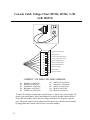
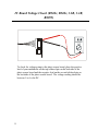
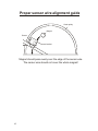
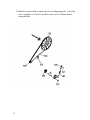
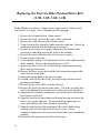
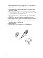
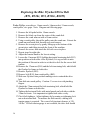
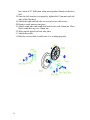
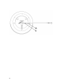
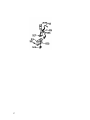
Horizon Fitness
2004-2005 Exercise
Bike Service Manual
R51, R52hr, B51, B52hr, 2.1R, 2.1B,
3.1R, 3.1B, R6055
If you have any questions, please call the Horizon Fitness Service Hotline at
1-800-244-4192
TABLE OF CONTENTS
Warranty
3
Safety Instructions
6
Basic Troubleshooting Tips
7
Required Tools
8
Preventive Maintenance
9
Console Troubleshooting
10
Resistance Troubleshooting
20
Drive Train Troubleshooting
25
Voltage Checkpoints
32
Exercise Bike Part Replacement
37
2
Bike Home Warranty
Models: R51, R52hr, B51 B52hr, R6055
LIMITED HOME USE WARRANTY
Horizon Fitness extends the following exclusive, limited warranty,
which shall apply to the use of the device in the home, for residential,
non-commercial purposes only. Any other use shall void this warranty.
Horizon Fitness hereby extends the following limited warranties for the
following components of the device, for the time period indicated:
FRAME – LIFETIME
Horizon Fitness warrants the frame against defects in workmanship and
materials for the life of the product, so long as it remains in the
possession of the original owner.
BRAKE – R51, B51: 5 YEARS R52hr, B52hr, R6055: 10 YEARS
Horizon Fitness warrants the brake against defects in workmanship and
materials for the above warranty periods, so long as it remains in the
possession of the original owner.
ELECTRONICS & PARTS – ONE YEAR
Horizon Fitness warrants the electronic components and all original
parts against defects in workmanship and materials for a period of one
year from the date of purchase, so long as the device remains in the
possession of the original owner.
LABOR – R51, B51: 90 DAYS R52hr, B52hr, R6055: ONE YEAR
Horizon Fitness shall cover the labor cost for the repair of the device for
the above warranty periods, so long as the device remains in the
possession of the original owner.
3
Models: 2.1B, 2.1R, 3.1B, 3.1R
FRAME – LIFETIME
Horizon Fitness warrants the frame against defects in workmanship and
materials for the life of the product, so long as it remains in the
possession of the original owner.
BRAKE – LIFETIME
Horizon Fitness warrants the frame against defects in workmanship and
materials for the life of the brake, so long as it remains in the possession
of the original owner.
ELECTRONICS & PARTS – TWO YEARS
Horizon Fitness warrants the electronic components and all original
parts against defects in workmanship and materials for a period of two
years from the date of purchase, so long as the device remains in the
possession of the original owner.
LABOR – ONE YEAR
Horizon Fitness shall cover the labor cost for the repair of the device for
a period of one year from the date of original purchase, so long as the
device remains in the possession of the original owner.
4
EXCLUSIONS AND LIMITATIONS
This warranty applies only to the original owner and is not transferable.
This warranty is expressly limited to the repair or replacement of a
defective frame, electronic component, or defective part and is the sole
remedy of the warranty. The warranty does not cover normal wear and
tear, improper assembly or maintenance, or installation of parts or
accessories not originally intended or compatible with the exercise
equipment as sold. The warranty does not apply to damage or failure
due to accident, abuse, corrosion, discoloration of paint or plastic, or
neglect. Horizon Fitness shall not be responsible for incidental or
consequential damages. All returns must be pre-authorized by Horizon
Fitness. Horizon Fitness’ obligation under this warranty is limited to
replacing or repairing, at Horizon Fitness’ option, the product at one of
its authorized service centers. A Horizon Fitness authorized service
center must receive all products for which a warranty claim is made.
These products must be received with all freight and other transportation
charges prepaid, accompanied by sufficient proof of purchase. Parts and
electronic components reconditioned to As New Condition by Horizon
Fitness or its vendors may sometimes be supplied as warranty
replacement parts and constitute fulfillment of warranty terms. This
warranty gives you specific legal rights, and your rights may vary from
state to state.
WARRANTY REGISTRATION
Your warranty card must be completed and sent to Horizon Fitness or
register on line at www.horizonfitness.com, before a warranty claim can
be processed.
5
Important Safety Instructions
Warning statements indicate a particularly dangerous activity. Please read
the following warnings before using, repairing or maintaining your exercise
equipment:
• Never drop or insert any object into any opening.
• Do not remove the exercise equipment’s side covers. Service should
be performed only by an authorized Horizon Fitness service provider
• Never operate the exercise equipment if it is not working properly, if
it has been damaged, or immersed in water.
• Visually check the machine before beginning service or maintenance
operations. If it is not completely assembled or is damaged in any
way, exercise extreme caution while operating and checking the
exercise equipment.
• Do not use outdoors.
• Do not wear clothing that might catch on any part of the exercise
equipment.
• Use this exercise product for its intended use as described in the
Owner’s guide. Do not use attachments not recommended by the
manufacture.
• Use care when getting on of off the exercise equipment. Use the
handrails whenever possible.
• Do not rock the unit. Do not stand or climb on the handrails,
electronic console, or side covers.
• If you experience chest pains, nausea, dizziness or shortness of breath,
stop exercising immediately and consult your physician before
continuing.
CHILDREN
• Keep children off of your exercise equipment at all times.
• When the exercise equipment is in use, young children and pets
should be kept at least 10 feet away.
6
Basic Troubleshooting Tips
When using this service guide for troubleshooting problems on a Horizon
Fitness bike or elliptical, follow the step-by-step procedures listed in the
troubleshooting section. The step-by-step procedures start with the most
basic checkpoints to more extensive checkpoints. However, it is still
extremely important to follow the step-by-step procedures from start to
finish to ensure that the proper steps are taken to resolve all issues.
It is also helpful to have a known good component to verify the defective
part to eliminate troubleshooting errors.
When calling for service assistance or technical support, be sure to gather as
much information as possible such as the model name, serial number and a
very detailed description of the defect (i.e. when does problem occur, how
often, etc.).
7
Required Tools and Equipment
The following list is a summary of the tools and equipment required by
the procedures in this manual.
Phillips screwdrivers
Flat-head screwdrivers
Digital multi-meter
Allen wrench set (Metric)
Open-end wrenches of assorted sizes (Metric)
½” drive ratchet and sockets of assorted sizes
Bearing loctite
Cable ties
Needle nose pliers
Damp cloth
Rubber mallet
Drop cloth (to protect floor surfaces)
Ruler
Snap ring pliers
Wire cutters
Crank Puller*
Bearing Extractor*
* Available through Horizon Fitness at cost.
8
Preventative Maintenance Procedures
Cleanliness of your Horizon Fitness exercise equipment and its
operating environment will keep maintenance problems and service
calls to a minimum. For this reason, Horizon Fitness recommends that
the following preventive maintenance schedule be followed.
After Each Use
• Wipe down the console, handlebars, and side covers with a damp
cloth. Never use solvents, as they can cause damage to the
exercise equipment.
Every Week
Clean underneath the exercise equipment, following these steps:
• Move the exercise equipment to a remote location.
• Wipe or vacuum any dust particles or other objects that may have
accumulated underneath the exercise equipment.
• Return the exercise equipment to its previous position.
Every Month
• Inspect all assembly bolts of the machine for proper tightness.
9
CONSOLE TROUBLESHOOTING
CONTENTS
No display on console
11
Partial LCD display on console
13
No RPM, speed or watts readout
14
Sensor wire continuity check
15
Console resets intermittently
16
Erratic or no heart rate readout
17
Switching from mph to km
18
10
No Display on Console
Possible causes:
1. Weak batteries (R51, B51)
2. Loose connection between power supply and power jack (R52hr, B52hr,
2.1R, 2.1B, 3.1R, 3.1B, R6055)
3. Loose connection between console cable and console (R52hr, B52hr,
2.1R, 2.1B, 3.1R, 3.1B, R6055)
4. Defective power supply (R52hr, B52hr, 2.1R, 2.1B, 3.1R, 3.1B, R6055)
5. Defective photo sensor board (R52hr, B52hr, 3.1R, 3.1B, R6055)
6. Pinched or cut console cable (R52hr, B52hr, 2.1R, 2.1B, 3.1R, 3.1B,
R6055)
7. Defective console (All Models)
Fix:
1. Check voltage on batteries or replace with known good batteries (R51,
B51).
2. Check connection between power supply and power jack (R52hr,
B52hr, 2.1R, 2.1B, 3.1R, 3.1B, R6055).
3. Remove the console by removing the four attachment screws and
verify that the console cable is properly attached to the console
(R52hr, B52hr, 2.1R, 2.1B, 3.1R, 3.1B, R6055).
4. Verify that the proper amount of voltage is coming from the power
supply. Reference the power supply voltage checkpoint in the table of
contents (R52hr, B52hr, 2.1R, 2.1B, 3.1R, 3.1B, R6055).
11
5. Verify voltage going to photo sensor board (see photo sensor board
voltage checkpoint in table of contents). Replace if necessary (R52hr,
B52hr, 3.1R, 3.1B, R6055).
6. Perform a physical check on the console cable to verify that it is not
pinched or cut. Verify that proper voltage is present at the end of the
console cable, which plugs into the console (see console cable voltage
chart in table of contents). Replaced if necessary (R52hr, B52hr,
2.1R, 2.1B, 3.1R, 3.1B, R6055).
7. If problem persists, replace console (All Models).
12
Partial LCD Display on Console
Possible causes:
1. Weak batteries (R51, B51).
2. Console subjected to cold temperatures (All Models).
3. Defective console (All Models).
Fix:
1. Check voltage on batteries or replace with known good batteries (R51,
B51).
2. Allow console to warm to room temperature. It may be necessary to
gently massage the LCD crystal with your hand to allow for full
display. Pressing against the LCD crystal with excessive force may
damage the crystal.
3. If problem persists, replace console.
13
Only Time Works On Console
(No workload, distance, etc.)
Possible causes:
1. Poor connection between sensor wire and console (All Models).
2. Missing rpm magnet on crank assembly (All Models).
3. Defective sensor wire (All Models).
4. Defective console (All Models).
Fix:
1. Verify proper connection between sensor wire and console by
removing console and snapping console wire and sensor wires
together firmly (R51, B51). For R52hr, B52hr, 2.1R, 2.1B, 3.1R,
3.1B and R6055 models, remove the side cover and verify that the
sensor wire is properly connected to the console cable connection.
2. Verify that magnet is installed in crank assembly.
3. Inspect sensor wire for damage. Check continuity of rpm sensor wire
(see sensor wire continuity checkpoint in table of contents). Replace
if defective.
4. If problem persists, replace console.
14
RPM Sensor Continuity Check
2.0 Hz
To check for continuity on the sensor wire, turn your multimeter setting
to Ohms. Place the positive lead of your multimeter on the tip of the
sensor wire jack and the negative lead on the outside of the sensor wire
jack. There must be an rpm present in order to get continuity through the
sensor wire.
15
Console Resets Intermittently
Possible causes:
1. Poor connection between sensor wire and console (R51, B51).
2. Weak batteries in console (R51, B51).
3. Loose connection between the power jack and power supply (R52hr,
B52hr, 2.1R, 2.1B, 3.1R, 3.1B, R6055)
4. Sensor wire is pinched or cut (R52hr, B52hr, 2.1R, 2.1B, 3.1R, 3.1B,
R6055).
5. Defective console (All Models).
Fix:
1. Verify proper connection between sensor wire and console by
removing console and snapping console wire and sensor wires
together firmly (R51, B51).
2. Verify battery voltage or replace with know good batteries (R51,
B51).
3. Verify that the power supply is securely inserted into the power jack.
Replace power supply and/or power jack if there is a loose connection
(R52hr, B52hr, 2.1R, 2.1B, 3.1R, 3.1B, R6055).
4. Inspect sensor wire for damage. Check continuity of rpm sensor wire.
Replace if defective (R52hr, B52hr, 2.1R, 2.1B, 3.1R, 3.1B, R6055).
5. If problem persists, replace console (All Models).
16
Erratic or No Heart Rate Readout
Possible causes:
1. Improper hand placement.
2. Verify console display is on pulse screen (R51, B51).
3. Verify wiring of pulse grips (2.1R, 2.1B, 3.1R, 3.1B, R6055).
4. Defective remote sensor in seat back (2.1R, 3.1R).
5. Defective chest strap (3.1R, 3.1B).
6. Defective console.
Fix:
1. Make sure that both hands are holding the grip pulse handlebars. It is
important to use a loose cupping hold when using the grip pulse.
2. Press the select button until a P is displayed on the console screen
(R51hr, B51hr, 2.1R, 2.1B, 3.1R, 3.1B, R6055).
3. Replace pulse grips (2.1R, 2.1B, 3.1R, 3.1B, R6055).
4. Check batteries and connections for remote sensor located in seat back
(2.1R, 3.1R).
5. If the problem persists, replace the console.
17
Switching the Console from MPH to KM
R51, B51
Once you insert the batteries into the back of the console, the console will be
set to mph. To switch from mph to km, press and hold the select button for
three seconds. While holding the select button down, the time on the
console will begin to increase. Once the select button is held for three
seconds, the time will reset to zero. Continue to hold the select button for
two additional seconds. Again the time will begin to increase but will reset
to zero once the select button is held for two seconds. The console is now
set for km. To switch back to mph, simply remove the batteries and replace.
Note: To verify speed setting, upon powering up console, look for a 0 or 1
in the upper right hand corner of display. 0 represents Miles and 1
represents KM.
R52hr, B52hr, R6055:
Remove console and flip switch on back of console control board to
appropriate speed setting.
Note: To verify speed setting, upon powering up console, look for MILE or
KM to flash briefly on top of display.
2.1B, 2.1R:
Remove console and flip switch on back of console control board to
appropriate speed setting.
Note: To verify speed setting, press and hold the time +/- buttons
simultaneously and check for a 0 or 1 in right hand display window. 0
represents Miles and 1 represents KM.
18
3.1B, 3.1R:
Press Resistance +/- buttons simultaneously for a few seconds to get into
Engineering Mode. Press Select to change Engineering Mode to ENG4.
Press Start to enter ENG4. Once in this mode, press select to toggle between
Miles and KM. Once correct speed setting is selected, press and hold Stop
to exit ENG4.
Note: To verify speed setting, upon powering up console, look for MI or KM
to flash briefly on display.
19
RESISTANCE TROUBLESHOOTING
CONTENTS
No resistance change
21
Erratic/Continuous resistance change
22
Resistance is too hard or too weak
24
20
No Resistance Change
Possible causes:
1. Tension cable is not connected to tension knob (R51, B51, 2.1B, 2.1R
only).
2. Tension cable is not connected to the brake (all models).
3. Tension cable is defective (R51, B51, 2.1B, 2.1R only).
4. Photo sensor board is defective (R52hr, B52hr, 3.1B, 3.1R, R6055
only).
5. Servomotor is defective (R52hr, B52hr, 3.1B, 3.1R, R6055 only).
6. Console cable is defective (R52hr, B52hr, 3.1B, 3.1R, R6055 only).
7. Console is defective (R52hr, B52hr, 3.1B, 3.1R, R6055 only).
Fix:
1. Remove tension knob from the console mast. Verify that the copper
cable from the tension knob is seated properly in the keyhole located
on the tension cable
2. Remove the side covers and verify that the tension cable is connected
to the brake.
3. If problem persists, replace the tension cable.
4. Check voltages of console cable (see console cable voltage chart in
table of contents) to verify proper function of photo sensor board,
servomotor, and console cable. Replace parts if defective.
5. If problem persists, replace the console.
21
Erratic or Continuous Resistance Change
Possible causes:
1. Tension cable is not connected properly to the tension knob (R51,
B51, 2.1B, 2.1R only).
2. Tension cable is not connected properly to the brake (all models).
3. Tension cable is binding or is crimped (R51, B51, 2.1B, 2.1R only).
4. Tension cable is defective (R51, B51, 2.1B, 2.1R only).
5. Zero switch is not positioned properly (R52hr, B52hr, 3.1B, 3.1R,
R6055 only)
6. Defective photo sensor board (R52hr, B52hr, 3.1B, 3.1R, R6055
only).
7. Defective console cable (R52hr, B52hr, 3.1B, 3.1R, R6055 only).
8. Defective console (R52hr, B52hr, 3.1B, 3.1R, R6055 only).
Fix:
1. Remove tension knob from the console mast. Verify that the copper
cable from the tension knob is seated properly in the keyhole located
on the tension cable.
2. Remove the side covers and verify that the tension cable is connected
securely to the brake.
3. Remove side covers and inspect for any binding or crimping in the
tension cable. Keep in mind that the tension cable has an outer plastic
sleeve with a small wire running internally. If the small internal wire
22
is binding or is crimped slightly, it will not move smoothly. Remove
any binding or crimping by repositioning the tension wire.
4. If problem persists, replace the tension cable.
5. Remove the side covers. Locate the servomotor and photo sensor
board. Below the servomotor, there should be a black sensor wire
(zero switch), which also connects to the photo sensor board. On the
zero switch, there is an orange switch that should come in contact
with the servomotor shaft when at resistance level 0. If the zero
switch does not come into connect with the servomotor, the resistance
will continuously cycle back and forth. To resolve, adjust the position
of the zero switch by loosening the two attach screws and reposition.
6. Check voltages of console cable (see console cable voltage chart in
table of contents) to verify proper function of photo sensor board,
servomotor, and console cable. Replace parts if defective.
7. If problems persist, replace the console (R52hr, B52hr, 3.1B, 3.1R,
R6055).
23
Resistance is Too Hard or Too Weak
Possible causes:
1. Tension cable is not connected properly to the tension knob (R51,
B51, 2.1B, 2.1R only).
2. Tension cable is not connected properly to the brake.
3. Tension cable is binding or is crimped (R51, B51, 2.1B, 2.1R only).
4. Verify that brake is within 2-3 mm from the brake at the highest
resistance level.
Fix:
1. Remove tension knob from the console mast. Verify that the copper
cable from the tension knob is seated properly in the keyhole located
on the tension cable.
2. Remove the side covers and verify that the tension cable is connected
securely to the brake.
3. Remove side covers and inspect for any binding or crimping in the
tension cable. Keep in mind that the tension cable has an outer plastic
sleeve with a small wire running internally. If the small internal wire
is binding or is crimped slightly, it will not move smoothly. Remove
any binding or crimping by repositioning the tension wire.
4. If magnetic brake is not within 2-3mm of flywheel at the highest
resistance level, follow the directions for adjusting the magnetic brake
(see adjusting the magnetic brake in the table of contents).
24
DRIVETRAIN PROBLEM TROUBLESHOOTING
CONTENTS
Noise internally while pedaling
26
Internal noise while pedaling at high resistance levels only
28
Rough feel while pedaling
29
Crank arms loosen during use
31
25
Noise Internally While Pedaling
Possible causes:
1. Crank disks rubbing against side cover.
2. Loose crank arms.
3. Pedals are loose or defective.
4. Improper alignment of the drive belt.
5. Crank pulley wheel is rubbing against the side of the brake assembly.
6. Defective flywheel or crank pulley wheel bearings.
Fix:
1. Inspect the crank disks as the machine is being used. If the crank disk
has some wobble to it as it is rotating, the crank disk may be rubbing
against the side cover. To resolve, verify which part of the crank disk
is hitting the side cover and remove the crank arm and crank disk
from the bike. Remove the crank disk from the crank arm by
removing the attachment screws. Insert additional washers between
the crank arm and crank disk in the area where the disk was rubbing
against the side cover. If problem persists, replace crank arm.
2. Remove the side covers and verify that the crank arms are tight.
There should not be any side-to-side play in the crank arms if
tightened properly. Tighten if necessary.
3. Tighten the pedals with a 15mm wrench. Remove and grease the
pedal threads if necessary. Replace pedals if necessary.
4. Remove the side covers and inspect the drive belt alignment. If the
drive belt is not centered on the one-way pulley, there may be
excessive noise created. Reposition the drive belt by carefully
26
walking the drive belt towards the appropriate direction with one
hand, while spinning the flywheel with the other. Take caution to
avoid pinched fingers.
5. Remove the side covers and manually spin the flywheel. Confirm that
there is approximately a 3mm gap between the crank pulley wheel and
the side of the brake assembly. If the crank pulley wheel is rubbing
against the brake assembly, manually push the brake assembly in the
appropriate direction. Verify that the proper gap has been achieved.
6. If problem persists, verify whether or not the noise is coming from the
crank pulley wheel bearings or the flywheel bearings. To verify
whether the crank or flywheel bearings are defective remove the side
covers and accent piece. Carefully turn the crank arms. Take caution
to avoid pinching fingers. Once the flywheel is spinning at a fairly
fast rpm, listen carefully to both sets of bearings (crank and flywheel
bearings). If it is still not apparent which set of bearings are defective,
place your hand on the bearing housing (cup that bearing is positioned
in) on the flywheel and feel for any excessive vibration or clicking on
both the right and left bearings housing. If there is not any vibration
in the flywheel bearings, if is more likely that the crank bearings are
defective. Replace as necessary.
When replacing either the crank or flywheel bearings, be sure to remove
any excess loctite after removing defective bearings and reinstalling new
bearings. Make sure that both the inner and outer diameters of the
bearings have fresh loctite applied before reinstalling new bearings.
27
Noise Internally While Pedaling at Higher
Resistance Levels Only
Possible causes:
1. Crank pulley wheel is rubbing against the side of the brake assembly.
2. Brake assembly is rubbing against the flywheel.
Fix:
1. Remove the side covers and manually spin the flywheel. Confirm that
there is approximately a 3mm gap between the crank pulley wheel and
the side of the brake assembly. If the crank pulley wheel is rubbing
against the brake assembly, manually push the brake assembly in the
appropriate direction. Verify that the proper gap has been achieved.
2. Remove the side covers and verify that there is approximately a 3mm
gap between the entire magnet surface of the brake assembly and the
flywheel. If the brake assembly is rubbing against the flywheel,
adjust the position of the brake assembly. Reference
replacing/adjusting the brake assembly in the table of contents.
28
Rough Feel While Pedaling
Possible causes:
1. Loose crank arms.
2. Loose or defective pedals.
3. Drive belt mis-aligned.
4. Defective flywheel or crank pulley wheel bearings.
Fix:
1. Remove the side covers and verify that the crank arms are tight.
There should not be any side-to-side play in the crank arms if
tightened properly. Tighten if necessary. If problems persist, replace
the crank axle nut with updated nut. Contact Horizon Fitness for
update kit.
2. Remove the pedals and apply white lithium grease to the pedal
threads. Reattach the pedals using a large 15mm wrench. If problem
persists, it may be necessary to replace the pedals.
3. Remove the side covers and inspect the drive belt alignment. If the
drive belt is not centered on the one-way pulley, there may be
excessive noise created. Reposition the drive belt by carefully
walking the drive belt towards the appropriate direction with one
hand, while spinning the flywheel with the other. Take caution to
avoid pinched fingers.
29
4. If problem persists, verify whether or not the noise is coming from the
crank pulley wheel bearings or the flywheel bearings. To verify
whether the crank or flywheel bearings are defective remove the side
covers and accent piece. Carefully turn the crank arms. Take caution
to avoid pinching fingers. Once the flywheel is spinning at a fairly
fast rpm, listen carefully to both sets of bearings (crank and flywheel
bearings). If it is still not apparent which set of bearings are defective,
place your hand on the bearing housing (cup that bearing is positioned
in) on the flywheel and feel for any excessive vibration or clicking on
both the right and left bearings housing. If there is not any vibration
in the flywheel bearings, if is more likely that the crank bearings are
defective. Replace as necessary.
When replacing either the crank or flywheel bearings, be sure to remove
any excess loctite after removing defective bearings and reinstalling new
bearings. Make sure that both the inner and outer diameters of the
bearings have fresh loctite applied before reinstalling new bearings.
30
Crank Arms Loosen During Use
Possible causes:
1. Crank axle nut is defective.
Fix:
1. Replace crank axle nut with updated nut. Contact Horizon Fitness for
update kit.
31
VOLTAGE READINGS
CONTENTS
Console cable voltage chart
33
Power supply voltage check
34
IC Board voltage check
35
RPM sensor continuity check
36
32
Console Cable Voltage Chart (R52hr, B52hr, 3.1B,
3.1R, R6055)
- +
P1
P2
P3
P4
- Imput from RPM Sensor
- Motor Ground
- Power to Photo-Optic Reset
- Power to Photo-Optic Count
- Power to Magnet Motor
P5
- Power to Magnet Motor
P6
- Input from RPM Sensor
P7
- Power to Console
P8
- Ground Wire
P9
- Power to Console
P10
CORRECT VOLTAGE FOR WIRE HARNESS:
P1
P2
P3
P4
P5
PURPLE 0 VOLTS DC
BLACK 0 VOLTS DC
ORANGE 5 VOLTS DC
BROWN 5 VOLTS DC
GREEN .46 VOLTS DC
P6
P7
P8
P9
P10
WHITE .46 VOLTS DC
YELLOW 5 VOLTS DC
GREY 9.5 VOLTS DC
BLUE 0 VOLTS DC
RED 5.5 VOLTS DC
To check for voltages coming from a specific part (i.e. sensor wire, power supply, DC
motor), place the negative lead of the multimeter in pin P9 (ground) and the positive
lead in the desired pin. Follow the pin voltages listed above to diagnosis a specific
part. The power supply must be plugged into the power jack, and the console should
be plugged into the console cable to receive accurate readings.
33
Power Supply Voltage Check (R52hr, B52hr, 3.1R,
3.1B, R6055)
16.5
With the power supply plugged in to the wall, place the positive lead of
your multimeter into the power supply jack and the negative lead on the
outside of the power supply jack. The voltage of the power supply
should be between 7.5-11.5 volts DC for models 2.1R, 3.1R, 2.1B, 3.1B
and between 14.5-16.5 volts DC for models R52hr, B52hr, and R6055.
34
IC Board Voltage Check (R52hr, B52hr, 3.1B, 3.1R,
R6055)
To check for voltage going to the photo sensor board, place the positive
lead of your multimeter on the top soldered pin on the backside of the
photo sensor board and the negative lead on the second soldered pin on
the backside of the photo sensor board. The voltage reading should be
between 5 to 6 volts DC.
35
RPM Sensor Continuity Check
2.0 Hz
To check for continuity on the sensor wire, turn your multimeter setting
to Ohms. Place the positive lead of your multimeter into the tip of the
sensor wire/console cable connection and the negative lead into the other
tip of the sensor wire/console cable connection. There must be an rpm
present in order to get continuity through the sensor wire (all models).
36
EXERCISE BIKE PART REPLACEMENT
CONTENTS
Removing the side case
38
Replacing the sensor wire
40
Proper sensor wire position
42
Replacing the console cable
43
Replacing the tension cable
44
Replacing the crank assembly
46
Replacing the flywheel/drive belt
48
Adjusting the magnetic brake
52
Replacing the servomotor
56
37
Removing the Exercise Bike Side Case
Tools: Phillips screwdriver, 14mm socket, 15mm wrench, crank puller.
Note: Diagram on following page.
1.
2.
3.
4.
Remove the pedal (T07) with a 15mm wrench.
Remove the black cap (Q11) from the center of the crank disk.
Remove the crank arm nut (T09) with a 14mm socket.
Using a crank puller, thread the puller onto the crank arm (AT1).
Extract the crank arm and crank disk from the axle and remove.
5. Remove the accent piece by gently lifting up at the bottom of the
accent piece and tilting towards the front of the machine.
6. Remove the screws that attach the side cover (Q02) in place.
7. Attach new side cover.
8. Attach the accent piece, placing the bottom tab into position first
then placing the top tab into position.
9. Attach the crank disk and crank arm to the crank axle. Place black
cap onto the center of the crank disk.
10. Replace pedal arm cap.
11. Attach the pedal.
12. Test ride the exercise bike to make sure it is working correctly.
38
39
Replacing the Exercise Bike RPM Sensor
(R51, B51, 2.1R, 2.1B)
Tools: Phillips screwdriver, 14mm socket, 15mm wrench, crank puller
1.
2.
3.
4.
Remove the left pedal with a 15mm wrench.
Remove the black cap from the center of the crank disk.
Remove the crank arm nut with a 14mm socket.
Using a crank puller, thread the puller onto the crank arm. Extract the
crank arm and crank disk from the axle and remove.
5. Remove the accent piece by gently lifting up at the bottom of the
accent piece and tilting towards the front of the machine.
6. Remove the screws that attach the left side cover in place.
7. Locate the sensor wire bracket. Remove the screw from the sensor
wire bracket.
8. Remove the old sensor wire from the sensor wire bracket.
9. Remove the console from the console mast. Attach the new sensor
wire to the old sensor wire, in order to fish the sensor through the
console mast.
10. Once the new sensor wire is fished through the console mast, attach
the new sensor wire to the sensor wire bracket.
11. Attach the sensor wire bracket onto the frame.
12. Turn crank by hand to make sure that there is a RPM reading on the
console. (If no RPM reading check to make sure the sensor is in the
correct position.
13. Attach the left side cover and secure with screws.
14. Attach the accent piece, placing the bottom tab into position first and
then placing the top tab into position.
15. Attach the crank disk and crank arm to the crank axle. Place black
cap onto the center of the crank disk.
16. Attach the pedal.
17. Test ride the exercise bike to make sure it is working correctly.
40
Replacing the Exercise Bike RPM Sensor
(R52hr, B52hr, 3.1R, 3.1B, R6055)
Tools: Phillips screwdriver, 14mm socket, 15mm wrench, crank puller
1.
2.
3.
4.
Remove the left pedal with a 15mm wrench.
Remove the black cap from the center of the crank disk.
Remove the crank arm nut with a 14mm socket.
Using a crank puller, thread the puller onto the crank arm. Extract the
crank arm and crank disk from the axle and remove.
5. Remove the accent piece by gently lifting up at the bottom of the
accent piece and tilting towards the front of the machine.
6. Remove the screws that attach the left side cover in place.
7. Locate the sensor wire bracket. Remove the screw from the sensor
wire bracket and remove the old sensor wire from the bracket.
8. Detach the sensor wire from the console cable.
9. Attach the new sensor wire to the sensor wire bracket and plug into
connector into console cable.
10. Attach the sensor wire bracket to the frame.
11. Turn crank by hand to make sure that there is a RPM reading on the
console. (If no RPM reading check to make sure the sensor is in the
correct position.
12. Attach the left side cover and secure with screws.
13. Attach the accent piece, placing the bottom tab into position first and
then placing the top tab into position.
14. Attach the crank disk and crank arm to the crank axle. Place black
cap onto the center of the crank disk.
15. Attach the pedal.
16. Test ride the exercise bike to make sure it is working correctly.
41
Proper sensor wire alignment guide
Crank pulley
Magnet
Sensor
Sensor bracket
Magnet should pass evenly over the edge of the sensor wire.
The sensor wire should not cover the whole magnet!
42
Replacing the Exercise Bike Console Cable
(R52hr, B52hr, 3.1R, 3.1B, R6055)
Tools: Phillips screwdriver, 14mm socket, 15mm wrench, 5mm Allen
wrench, crank puller
1.
2.
3.
4.
5.
Unplug power supply from the exercise bike.
Remove the left pedal with a 15mm wrench.
Remove the black cap from the center of the crank disk.
Remove the crank arm nut with a 14mm socket.
Using a crank puller, thread the puller onto the crank arm. Extract the
crank arm and crank disk from the axle and remove.
6. Remove the accent piece by gently lifting up at the bottom of the
accent piece and tilting towards the front of the machine.
7. Remove the screws that attach the left side cover in place
8. Unscrew the power jack from the frame.
9. Unplug the console cable from the sensor wire and IC Board.
10. Unscrew the console from the console mast. Unplug the console
cable from the console and attach the new console cable to the old
console cable, in order to fish the cable through the console mast.
You may need to unscrew the water bottle bracket screws in order to
fish the console cable easily.
11. Once the new console cable is fished through the console mast, plug
the proper connections to the sensor wire and IC Board.
12. Screw the power jack into position.
13. Attach the console and plug in the machine.
14. Turn crank by hand to make sure that there is a RPM reading on the
console and all other functions are working properly. (If no RPM
reading check to make sure the sensor is in the correct position.
17. Attach the left side cover and secure with screws.
18. Attach the accent piece, placing the bottom tab into position first and
then placing the top tab into position.
19. Attach the crank disk and crank arm to the crank axle. Place black
cap onto the center of the crank disk.
20. Attach the pedal.
21. Test ride the exercise bike to make sure it is working correctly.
43
Replacing the Exercise Bike Tension Cable
Tools: Phillips screwdriver, 14mm socket, 15mm wrench, crank puller
1. Turn the tension knob to the highest resistance level. Remove the
tension knob from the tension cable by pulling up on the tension knob.
2. Remove the screw that attaches the tension knob to the console mast,
using a Phillips screwdriver.
3. Remove the left pedal with a 15mm wrench.
4. Remove the black cap from the center of the crank disk.
5. Remove the crank arm nut with a 14mm socket.
6. Using a crank puller, thread the puller onto the crank arm. Extract the
crank arm and crank disk from the axle and remove.
7. Remove the accent piece by gently lifting up at the bottom of the
accent piece and tilting towards the front of the machine.
8. Remove the screws that attach the left side cover in place. Remove
the crank arm cover from the left pedal arm with a Phillips
screwdriver.
9. Locate the position where the tension cable attaches to the magnetic
brake. Disconnect the tension cable from the flywheel/brake
assembly.
10. Using a 10mm wrench, disconnect the nut that attaches the tension
cable to the main frame.
11. Fish the current tension knob through the console mast, and replace
with new cable.
12. Adjust the tension knob to the highest resistance level. Attach the
tension knob to the tension cable and secure to the console mast with
screw.
13. Connect the tension knob cable to the flywheel/brake assembly.
14. Slide the tension cable through the bracket on the main frame. Secure
by tightening the two 10mm nuts.
15. The proper resistance setting is set when the magnetic brake is 2-3
mm from the flywheel at the highest resistance setting.
16. Adjust the tension knob from the lowest to highest resistance settings
to ensure proper movement and position of the flywheel/brake
assembly.
17. Attach the left side cover and secure with screws.
18. Attach the accent piece, placing the bottom tab into position first then
placing the top tab into position.
44
19. Attach the crank disk and crank arm to the crank axle. Place black
cap onto the center of the crank disk.
20. Replace pedal arm cap.
21. Attach the pedal.
22. Test ride the exercise bike to make sure it is working correctly.
45
Replacing the Exercise Bike Crank Assembly
Tools: Phillips screwdriver, 14mm socket, 15mm wrench, crank puller, snap
ring pliers, rubber mallet, bearing Loctite. Note: Diagram on next page.
1.
2.
3.
4.
Remove the left pedal with a 15mm wrench.
Remove the black cap from the center of the crank disk.
Remove the crank arm nut with a 14mm socket.
Using a crank puller, thread the puller onto the crank arm. Extract the
crank arm and crank disk from the axle and remove.
5. Remove the accent piece by gently lifting up at the bottom of the
accent piece and tilting towards the front of the machine.
6. Remove the screws that attach the left side cover in place.
7. Repeat steps for right side.
8. Locate the idler spring (U05) and bracket (U06) on the right hand side
of the machine. Remove the attachment screw (U07).
9. Locate the c-clip on the left-hand side of the crank assembly axle, and
remove the c-clip with a snap ring pliers.
10. Tap the crank assembly (T05) from the frame, pounding on the lefthand side towards the right.
11. Once the crank assembly and the bearings are removed from the
frame, make sure to remove all dirt or grease from the frame bearing
housing.
12. Insert new crank assembly and bearings. Make sure that bearing locttite is applied to both the inner and outer diameter for both the left and
right bearings. Note: It is helpful to insert the right side bearing and
crank pulley first. Once the right bearing and the crank pulley are in
place, carefully tap the left bearing into position. It is best to let the
loctite set for 24 hours before using the bike.
13. Attach the c-clip in place on the crank assembly.
14. Attach the right side cover, crank arm, crank disk and black cap in
that order.
15. Attach the left side cover, crank arm, crank disk and black cap.
16. Attach the accent piece, placing the bottom tab into position first then
placing the top tab into position.
17. Attach the crank disk and crank arm to the crank axle. Place black
cap onto the center of the crank disk.
18. Attach the pedals.
46
19. Ride the exercise bike to make sure it is working properly. Once the
test is complete, it is best to let the Loctite set for 24 hours before
using the bike.
47
Replacing the Exercise Bike Flywheel/Drive Belt
(2.1R, 3.1R, 2.1B, 3.1B)
Tools: Phillips screwdriver, 11mm wrench, 14mm socket, 15mm wrench,
crank puller, vice grips. Note: Diagram on following page.
1.
2.
3.
4.
Remove the left pedal with a 15mm wrench.
Remove the black cap from the center of the crank disk.
Remove the crank arm nut with a 14mm socket.
Using a crank puller, thread the puller onto the crank arm. Extract the
crank arm and crank disk from the axle and remove.
5. Remove the accent piece by gently lifting up at the bottom of the
accent piece and tilting towards the front of the machine.
6. Remove the screws that attach the left side cover in place.
7. Repeat steps for right side.
8. Locate the idler spring (U05) and bracket (U06) on the right hand side
of the machine. Remove the attachment screw (U07).
9. Remove the three screws (R12) that hold the right bearing housing
(R09) onto the main frame.
10. Remove the three screws that hold the left bearing housing and idler
wheel onto the main frame.
11. Adjust the tension knob to the lowest setting.
12. Carefully slide the flywheel (R01) forward, being careful to avoid
pinching your fingers.
13. Remove the drive belt (R03) from the flywheel.
14. Remove the flywheel from the main frame. The brake assembly may
need to be adjusted back or removed to easily remove the flywheel.
15. Attach the new flywheel, making sure to attach the drive belt around
the flywheel clutch first.
16. Align the holes in the main frame and bearing housing, and insert the
three screws on the right side. Do not completely tighten any one
screw until all three have been threaded in partially.
17. Align the holes between the mainframe, idler wheel, and bearing
housing on the left side and insert the three screws. Do not
completely tighten any one screw until all three have been threaded in
partially.
18. Attach the idler spring bracket (U06) to the frame.
48
19. Attach the idler spring (U05) to the idler wheel (U01) first and then,
using a vice grips, carefully lift the idler spring up and hook it onto
the main frame.
20. Turn crank by hand to make sure that the drive belt and idler wheel
are properly aligned.
21. If the brake was adjusted or removed while removing the flywheel,
reposition the brake to the correct position. Turn the resistance knob
to verify that the brake is positioned properly.
22. Attach the right side cover, crank arm, crank disk and black cap in
that order.
23. Attach the left side cover, crank arm, crank disk and black cap.
24. Attach the accent piece, placing the bottom tab into position first then
placing the top tab into position.
25. Attach the crank disk and crank arm to the crank axle. Place black
cap onto the center of the crank disk.
26. Attach the pedals.
27. Ride the exercise bike to make sure it is working properly.
49
Replacing the Bike Flywheel/Drive Belt
(R51, R52hr, B51, B52hr, R6055)
Tools: Phillips screwdriver, 11mm wrench, 14mm socket, 15mm wrench,
crank puller, vice grips. Note: Diagram on following page.
1.
2.
3.
4.
Remove the left pedal with a 15mm wrench.
Remove the black cap from the center of the crank disk.
Remove the crank arm nut with a 14mm socket.
Using a crank puller, thread the puller onto the crank arm. Extract the
crank arm and crank disk from the axle and remove.
5. Remove the accent piece by gently lifting up at the bottom of the
accent piece and tilting towards the front of the machine.
6. Remove the screws that attach the left side cover in place.
7. Repeat steps for right side.
8. Adjust the tension knob to the lowest setting.
9. Loosen the 11mm nut (R15) holding horizontal tensioning bolt (R13)
into position on both sides of the flywheel (It is a good idea to note
the position of this nut in order to set the drive belt for the correct belt
tension.
10. Remove the 17mm nut (R16) and the belt-tensioning bolt, which hold
the flywheel to frame on both sides.
11. Remove flywheel (R03).
12. Remove belt (R10) from crank pulley (R02).
13. Slide new flywheel into position making sure to reattach the drive
belt.
14. Turn belt onto crank pulley. Caution: Use care to avoid pinching
fingers.
15. Attach the 17mm nut and the belt-tensioning bolt, which hold the
flywheel to frame on both sides.
16. Tighten the horizontal bolts with metal guards on both sides with the
11mm lock nuts. It is important to tighten both sides evenly.
17. Check belt tightness. Adjust tightness by loosening or tightening lock
nut on horizontal bolt. To measure the belt tension, a timing belt
tension gauge is required. The correct belt tension tolerance is 120140 lbs. If a belt tension gauge is not available, the drive belt should
50
have about 0.25” deflection when pressing down firmly on the drive
belt.
18. Once the belt tension is set properly, tighten the 17mm nuts on both
sides of the flywheel.
19. Attach the right and left side covers and secure with screws.
20. Replace wood grain accent piece.
21. Attach crank arms and crank disks and secure with 14mm nut. Place
black crank disk cap over 14mm nut.
22. Slide console mast boot back into place.
23. Attach the pedals.
24. Ride the exercise bike to make sure it is working properly.
51
Adjusting the Exercise Bike Magnetic Brake (3.1R,
3.1B)
Tools: Phillips screwdriver, 5mm Allen wrench, 15mm wrench, 14mm
socket, 13mm wrench, crank puller. Note: Diagram on following page.
1. Turn the tension knob to the highest resistance level. Remove the
tension knob from the tension cable by pulling up on the tension knob.
2. Remove the screw that attaches the tension knob to the console mast,
using a Phillips screwdriver.
3. Remove the left pedal with a 15mm wrench.
4. Remove the black cap from the center of the crank disk.
5. Remove the crank arm nut with a 14mm socket.
6. Using a crank puller, thread the puller onto the crank arm. Extract the
crank arm and crank disk from the axle and remove.
7. Remove the accent piece by gently lifting up at the bottom of the
accent piece and tilting towards the front of the machine.
8. Remove the screws that attach the left side cover in place. Remove
the crank arm cover from the left pedal arm with a Phillips
screwdriver
9. Locate the magnetic brake (S02).
10. The correct position for the magnetic brake is 2-3mm from the
flywheel at the highest resistance level.
11. Locate the 13mm nut (S11) attached to the magnetic brake spring
(S10). Adjust the nut clockwise to reduce the brake resistance and
counterclockwise to increase the brake resistance. By adjusting this
nut, the lower half of the brake will either move closer or further from
the flywheel.
12. It may be necessary to also adjust the top half of the magnetic brake.
To do this, loosen the two 5mm bolts (S08) that attach the magnetic
brake to the frame. Adjust the position of the magnetic brake closer or
further from the flywheel.
13. Attach the left side cover and secure with screws.
14. Attach the accent piece, placing the bottom tab into position first then
placing the top tab into position.
52
15. Attach the crank disk and crank arm to the crank axle. Place black
cap onto the center of the crank disk.
16. Replace pedal arm cap.
17. Attach the pedal.
18. Test ride the exercise bike to make sure it is working correctly.
53
Adjusting the Exercise Bike Magnetic Brake (3.1R,
3.1B)
Tools: Phillips screwdriver, 5mm Allen wrench, 15mm wrench, 14mm
socket, 13mm wrench, crank puller. Note: Diagram on following page.
1. Turn the tension knob to the highest resistance level. Remove the
tension knob from the tension cable by pulling up on the tension knob.
2. Remove the screw that attaches the tension knob to the console mast,
using a Phillips screwdriver.
3. Remove the left pedal with a 15mm wrench.
4. Remove the black cap from the center of the crank disk.
5. Remove the crank arm nut with a 14mm socket.
6. Using a crank puller, thread the puller onto the crank arm. Extract the
crank arm and crank disk from the axle and remove.
7. Remove the accent piece by gently lifting up at the bottom of the
accent piece and tilting towards the front of the machine.
8. Remove the screws that attach the left side cover in place. Remove
the crank arm cover from the left pedal arm with a Phillips
screwdriver
9. Locate the magnetic brake (S02).
10. The correct position for the magnetic brake is 2-3mm from the
flywheel at the highest resistance level.
11. Locate the 8mm short and long nut (A and B respectively) covering
the tension wire that is attached to the magnetic brake/flywheel
assembly. Loosen the short nut (A), and adjust the long nut (B)
clockwise to reduce the brake resistance and counterclockwise to
increase the brake resistance.
12. Attach the left side cover and secure with screws.
13. Attach the accent piece, placing the bottom tab into position first then
placing the top tab into position.
14. Attach the crank disk and crank arm to the crank axle. Place black
cap onto the center of the crank disk.
15. Replace pedal arm cap.
16. Attach the pedal.
17. Test ride the exercise bike to make sure it is working correctly.
54
55
Replacing the Bike Servomotor/IC Board (R52hr,
3.1B, 3.1R, R6055)
Tools: Phillips screwdriver, 14mm socket, 15mm wrench, 2.5mm wrench,
5mm Allen wrench, crank puller. Note: Refer to diagram on following
page.
1.
2.
3.
4.
5.
Unplug power supply from exercise bike.
Remove the left pedal with a 15mm wrench.
Remove the black cap from the center of the crank disk.
Remove the crank arm nut with a 14mm socket.
Using a crank puller, thread the puller onto the crank arm. Extract the
crank arm and crank disk from the axle and remove.
6. Remove the accent piece by gently lifting up at the bottom of the
accent piece and tilting towards the front of the machine.
7. Remove the screws that attach the left side cover in place.
8. Unplug the console cable from the IC Board.
9. Remove the brake cable from the servomotor (S25) with a 2.5mm
Allen wrench.
10. Remove the entire servomotor assembly bracket (S14) from the frame.
11. Replace with new servomotor assembly.
12. Attach the brake cable to the servomotor.
13. Plug in the console cable to the IC Board.
14. Plug in the machine.
15. Turn crank by hand to make sure that there is a RPM reading on the
console and all other functions are working properly. (If no RPM
reading check to make sure the sensor is in the correct position.
Make sure the resistance is working properly.
16. Attach the left side cover and secure with screws.
17. Attach the accent piece, placing the bottom tab into position first then
placing the top tab into position.
18. Attach the crank disk and crank arm to the crank axle. Place black
cap onto the center of the crank disk.
18. Replace pedal arm cap.
19. Attach the pedal.
20. Test ride the exercise bike to make sure it is working correctly.
56
57
Notes
58


![У]о:(mЧєь{Сr˙„~®M −Ї‹ОЄ* hˇОˆt](http://vs1.manualzilla.com/store/data/006000975_1-aa867c7069e2492e9edc151c99229eb0-150x150.png)