1
Martin ShowDesigner
User manual
Rev.: 7/10/2015, 11:49 AM
© 2015 Martin Professional A/S, Lighthouse Holland
Martin Show Designer Help
© 2015 Martin Professional A/S, Lighthouse Holland
All rights reserved. No parts of this work may be reproduced in any form or by any means - graphic, electronic, or
mechanical, including photocopying, recording, taping, or information storage and retrieval systems - without the
written permission of the publisher.
Products that are referred to in this document may be either trademarks and/or registered trademarks of the
respective owners. The publisher and the author make no claim to these trademarks.
While every precaution has been taken in the preparation of this document, the publisher and the author assume no
responsibility for errors or omissions, or for damages resulting from the use of information contained in this
document or from the use of programs and source code that may accompany it. In no event shall the publisher and
the author be liable for any loss of profit or any other commercial damage caused or alleged to have been caused
directly or indirectly by this document.
Printed: July 2015
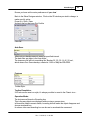
Publisher
Martin Professional A/S
Lighthouse Holland BV
Managing Editor
Paul Pelletier
Technical Editors
Stefan Montanus
Marco J.Westveer
Ofer Brum
Special thanks to:
Marco, Stefan, Ofer, Chris West and all MSD users for their
feedback s
Contents
I
Table of Contents
Foreword
0
Part I Introduction
2
1 MSD Pro
...................................................................................................................................
and MSD Lite
2
2 Software
...................................................................................................................................
Modules
3
3 Hardware
...................................................................................................................................
Requirements
4
Part II MSD Basic knowledge
7
1 Icons ................................................................................................................................... 7
2 Hotkeys
................................................................................................................................... 13
3 System
...................................................................................................................................
Axis
16
4 Fast-Switch
................................................................................................................................... 17
19
Part III ShowDesigner
1 Menus................................................................................................................................... 19
2 Layout................................................................................................................................... 37
3 Window
...................................................................................................................................
Management
38
4 Display
...................................................................................................................................
Mode
43
5 Settings
................................................................................................................................... 44
Preferences .......................................................................................................................................................... 45
Rendering .........................................................................................................................................................
Default Settings
46
Object Snap
......................................................................................................................................................... 53
System Untis
......................................................................................................................................................... 55
Gamma ......................................................................................................................................................... 56
Paths
......................................................................................................................................................... 57
DirectX ......................................................................................................................................................... 60
Language ......................................................................................................................................................... 61
Preferences
.........................................................................................................................................................
Options
62
6 Camera
................................................................................................................................... 64
Cam era Properties
..........................................................................................................................................................
2D
66
Cam era Properties
..........................................................................................................................................................
3D
67
Cam era Save/Delete
.......................................................................................................................................................... 69
7 Fixtures
................................................................................................................................... 71
Fixture List .......................................................................................................................................................... 72
Im porting Fixture
..........................................................................................................................................................
in a Scene
73
Inserting Fixture
..........................................................................................................................................................
in a Scene
75
Select and m anipulate
..........................................................................................................................................................
fixture
76
Replacing one..........................................................................................................................................................
or m any fixtures in a scene
81
Look Through..........................................................................................................................................................
Fixture
83
8 Objects
................................................................................................................................... 84
Object List .......................................................................................................................................................... 84
Im porting Objects
..........................................................................................................................................................
in a Scene
86
Inserting Object
..........................................................................................................................................................
in a Scene
88
© 2015 Martin Professional A/S, Lighthouse Holland
Rev.: 7/10/2015, 11:49 AM
I
II
Martin Show Designer Help
Select and m anipulate
..........................................................................................................................................................
object
89
Changing Object
..........................................................................................................................................................
Properties
91
Duplicate Object
..........................................................................................................................................................
or Fixture
92
Aling objects ..........................................................................................................................................................
or fixtures
95
9 Grouping
...................................................................................................................................
objects and fixtures
96
Group
.......................................................................................................................................................... 96
Assem bly
.......................................................................................................................................................... 98
Subtractive Grouping
.......................................................................................................................................................... 101
Intersect Grouping
.......................................................................................................................................................... 102
10 Fixture
...................................................................................................................................
Block
103
Creating a fixture
..........................................................................................................................................................
block
104
Inserting a fixture
..........................................................................................................................................................
block in a scene
105
11 Scene
...................................................................................................................................
Block
106
Creating a scene
..........................................................................................................................................................
block
106
Inserting a scene
..........................................................................................................................................................
block in a scene
108
12 Dynamic
...................................................................................................................................
Objects
109
How to use Dynam
..........................................................................................................................................................
ic Object in a Scene
112
13 Materials
...................................................................................................................................
and Textures
115
Material Base.......................................................................................................................................................... 119
Material Special
.......................................................................................................................................................... 122
Material Texture
.......................................................................................................................................................... 124
Material Bump
......................................................................................................................................................... 128
Color Selection
.......................................................................................................................................................... 130
14 Rendering
................................................................................................................................... 131
Rendering Creation
.......................................................................................................................................................... 133
Saving a Rendering
.......................................................................................................................................................... 135
15 Lux Meter
................................................................................................................................... 137
16 Cuelist
................................................................................................................................... 138
17 DMX ...................................................................................................................................
Control
142
18 Layers
................................................................................................................................... 144
19 Fast-Patch
................................................................................................................................... 146
20 Printing
...................................................................................................................................
in ShowDesigner module
148
21 Fixtures
...................................................................................................................................
automatically imported in a scene at startup
151
153
Part IV Modeler
1 Menu................................................................................................................................... 153
2 Layout
................................................................................................................................... 169
3 Windows
...................................................................................................................................
Management
169
4 Display
...................................................................................................................................
Mode
174
5 Settings
................................................................................................................................... 175
Preferences.......................................................................................................................................................... 176
Rendering.........................................................................................................................................................
Default Settings
177
Object Snap
......................................................................................................................................................... 184
System Untis
......................................................................................................................................................... 186
Gamma ......................................................................................................................................................... 187
Paths
......................................................................................................................................................... 188
DirectX ......................................................................................................................................................... 191
Rev.: 7/10/2015, 11:49 AM
© 2015 Martin Professional A/S, Lighthouse Holland
Contents
III
Language......................................................................................................................................................... 192
Preferences
.........................................................................................................................................................
Options
193
6 Primitives
................................................................................................................................... 195
7 Primitives
...................................................................................................................................
Properties
197
8 Object
...................................................................................................................................
List
200
9 Import
...................................................................................................................................
DXF and others
201
10 Material
...................................................................................................................................
List
204
11 Light...................................................................................................................................
Source Properties
208
211
Part V 3D Visualizer
1 Introduction
................................................................................................................................... 211
Layout
Scene Area
Tool Bars
Side Bar
.......................................................................................................................................................... 211
.......................................................................................................................................................... 212
.......................................................................................................................................................... 213
.......................................................................................................................................................... 214
2 Getting
...................................................................................................................................
Started
215
Loading a Scene
.......................................................................................................................................................... 215
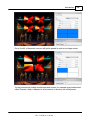
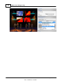
Creating a Scene
.......................................................................................................................................................... 216
Adding Objects
.........................................................................................................................................................
to the scene contents
218
Adding Fixtures
.........................................................................................................................................................
to the scene contents
220
Placing Objects
.........................................................................................................................................................
in the Scene
222
Placing Fixtures
.........................................................................................................................................................
in the Scene
225
Patching and
.........................................................................................................................................................
Controling Fixtures
228
Manually
......................................................................................................................................... 229
DMX
......................................................................................................................................... 231
3 Cameras
................................................................................................................................... 232
Predefined Cam
..........................................................................................................................................................
eras
233
Cam era Operations
.......................................................................................................................................................... 234
Saving and Loading
..........................................................................................................................................................
cam eras
235
4 Media
...................................................................................................................................
Feeds
238
Creating Media
..........................................................................................................................................................
Feeds
238
Using Media ..........................................................................................................................................................
Feeds
240
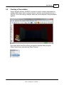
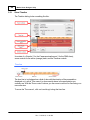
5 Creating
...................................................................................................................................
a Presentation
243
Show Tim eline
.......................................................................................................................................................... 244
DMX Track .......................................................................................................................................................... 247
Cam era Anim
..........................................................................................................................................................
ation Track
250
Recording a Video
.......................................................................................................................................................... 253
6 Reference
................................................................................................................................... 256
Menu
.......................................................................................................................................................... 256
Toolbar buttons
.......................................................................................................................................................... 269
Sidebar
.......................................................................................................................................................... 271
Environment
......................................................................................................................................................... 271
Camera ......................................................................................................................................................... 275
Orientation
......................................................................................................................................................... 276
Info
......................................................................................................................................................... 277
Parameters
......................................................................................................................................................... 278
Fan Focus......................................................................................................................................................... 279
Scene Library
.........................................................................................................................................................
Contents
280
Scene Contents
......................................................................................................................................................... 280
© 2015 Martin Professional A/S, Lighthouse Holland
Rev.: 7/10/2015, 11:49 AM
III
IV
Martin Show Designer Help
Contents
......................................................................................................................................... 281
Layers
......................................................................................................................................... 281
Media
......................................................................................................................................... 281
Show
......................................................................................................................................................... 281
Preference
......................................................................................................................................................... 281
Report View .......................................................................................................................................................... 282
285
Part VI Paperwork
1 Illuminance
...................................................................................................................................
Map
285
291
Part VII Fast Net Render
1 What...................................................................................................................................
is MSD Fast Net-Render
291
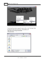
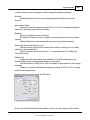
2 Fast Net-Render
...................................................................................................................................
Client
291
3 Fast Net-Render
...................................................................................................................................
Server
299
Part VIII MSD Tools and Utilites
302
1 MSD ...................................................................................................................................
Scene Compactor
302
304
Part IX References
1 Formulas
................................................................................................................................... 304
2 Links................................................................................................................................... 305
Index
306
Rev.: 7/10/2015, 11:49 AM
© 2015 Martin Professional A/S, Lighthouse Holland
Introduction
Part
I
2
1
Martin Show Designer Help
Introduction
Welcome to Martin ShowDesigner!
Martin ShowDesigner is a unique and user-friendly lighting and set-design software
package useful in developing realistic 3D lighting simulations in both architectural and
entertainment fields. Useful as a high quality production or sales presentation tool,
ShowDesigner allows you to create realistic set and lighting design renderings using
lighting, reflection, transparency, shadow and smoke.
In the architectural field, ShowDesigner can be used to realistically demonstrate the
enhancing effects of lighting on buildings, bridges, monuments or any structure.
Imagine creating realistic renderings of a building, subtly changing lighting, shadow and
reflection in order to obtain the best solution based on different fixture positions, spread
angles and setbacks.
Conveniently create lighting designs from your own PC or laptop. Forget timeconsuming scale modules and detailed drawings. Make positional and effect alterations
quickly and easily, then view them on screen.
ShowDesigner gives you the ability to present to your customer a variety of looks,
multiple realistic renderings that are appealing to view and easy to understand.
ShowDesigner calculates the luminous intensity on any surface, taking into account the
color, refraction, absorption, reflectance and transparency. Ambient light can be
adjusted to any level when calculating dawn, day, dusk or night environments. The
renderings can be saved in BMP or JPEG format and displayed via any picture viewer.
ShowDesigner eliminates the time consuming task of producing scale models and
detailed drawings, letting you spend less time "on location."
ShowDesigner features a very realistic Offline programming module, enabling the
lighting programmer to connect his console to the ShowDesigner and start
programming using virtual fixtures in the Offline.
Rental companies can pre-program shows in realistic real time 3D visualization thereby
saving time and money on the production budget.
With the ShowDesigner you can give your customer the confidence that they have
picked the best solution. And give yourself the confidence that you have presented the
highest quality visualization simulation available, while at the same time saving both
time and money.
1.1
MSD Pro and MSD Lite
MSD Pro and MSD Lite
This document is written for use with the full Pro version of the software.
If you have another version you will find that some of the functions differ slightly, or are
© 2015 Martin Professional A/S, Lighthouse Holland
Rev.: 7/10/2015, 11:49 AM
Introduction
3
not available.
If you want to upgrade to a Pro version, please contact your local Martin supplier for
more information.
1.2
Software Modules
ShowDesigner
The main program works in a full 3D environment. Here, different objects and fixtures
combine to form a stage, building or whatever environment is desired.
It is possible to work in real time wire frame or solid mode. Set and lighting design can
be simulated easily and extremely realistically due to the MSD's advanced rendering
capabilities.
The MSD calculates the luminous intensity of any surface and takes into account the
surface of any object in terms of color, refraction, absorption, reflectance and
transparency.
The ambient light level can be adjusted at any level. Renderings can be saved in bitmap
or JPEG format and displayed via any standard Windows picture viewer.
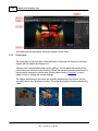
3D Visualizer
A very useful tool for pre-programming of any kind of show. Any DMX controller can be
connected via a DMX interface for easy offline programming.
An interface for laptop users is also available. In 3D Visualiser, very precise preprogramming is possible.
It can display most fixture functions such as movement (even the head of a moving head
will move accordingly), intensity, fixed colors, CMY color mixing, gobos, framing, iris and
more.
Camera positions and angles can be easily changed on the fly, making it fast to study a
light show from different viewing positions.
The show can be recorded in real time and saved as a video clip in various formats
such as AVI and MOV. It is then possible to view a pre-programmed show using any
standard Windows video viewer
Model
A handy 3D CAD program for creating or modifying objects. Objects can be built from
scratch using different primitives like cubes, pyramids, toroids, etc., or they can be a
modification of an already existing object from the library. The object library contains
images of chairs, stage elements, people, trussing of various manufacturers, etc. It is
© 2015 Martin Professional A/S, Lighthouse Holland
Rev.: 7/10/2015, 11:49 AM
4
Martin Show Designer Help
also possible to import 3D DXF files.
Paper
Modern productions require a plethora of paperwork – the Martin Show Designer
makes this easy to generate using the Paper Module.
This tool can be used to create plans with views in any scale and from any angle.
Add in a key, fixture lists, information blocks and even pictures. It also creates easy to
use and edit fixture and patching lists.
Fast Net-Render Client & Server (Pro version Only)
The Show Designer's ability to create a high quality rendering of your show is a very
powerful tool.
However it does take a considerable amount of computer power to achieve and can
take quite some time too.
The Fast Net Render system is there to speed up this process. It utilizes the power of
other computers, connected to your own, via a network to speed up the rendering
process.
Tools
Scene Compactor
This utility can be used to clean up a scene from unused objects, fixture, cues, and
material.
1.3
Hardware Requirements
Computer
For the most satisfying user experience you should use the best machine that
you can, with a fast processor and plenty of memory.
At least you need a graphics card with hardware support for DirectX 9 with
hardware support for Transform & Lighting (T&L), and vertex and pixel shaders
version 2 or higher. (version 3 recommended for support of all effects).
Operating Systems
This fully integrated package runs on Windows 7 or higher.
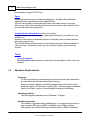
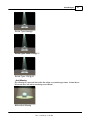
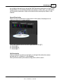
Hardware protection
The software is protected with a hardware key, so you will need a free port on
your computer. MSD uses a WIBU CodeMeter key, a USB port edition.
(This can also be a Martin One-Key, which basically is a WIBU CodeMeter).
© 2015 Martin Professional A/S, Lighthouse Holland
Rev.: 7/10/2015, 11:49 AM
Introduction
In some cases, the hardware key is build in the Martin Controller itself, and
accessible over the network.
The WIBU key looks something like this:
© 2015 Martin Professional A/S, Lighthouse Holland
Rev.: 7/10/2015, 11:49 AM
5
MSD Basic
knowledge
Part
II
MSD Basic knowledge
2
MSD Basic knowledge
Icons
Hotkeys
Display Mode
System Axis
Window Management
Fast Switch
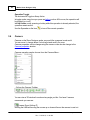
2.1
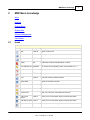
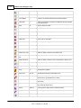
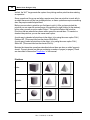
Icons
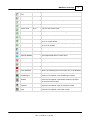
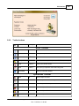
Common icons
Icon
Item
Hotkeys
Description
New
CTRL+N
Opens a new Scene
Open
CTRL+O
Allows you to open saved scenes
Save
CTRL+S
Saves current scene
Delete
DEL
Deletes the currently selected object or fixture
Turn operation off Spacebar
Turn off the current operation (move, scale, Rotate, etc…)
Undo
CTRL+Z
Undoes your previous action
Redo
CTRL+Y
Redo you're your previous action after using undo
Print
CTRL+P
Prints the currently selected window
About MSD
Opens an information window
Show/Hide beam
Hides all beams from fixtures
Light Mode
L
Prevents you selecting any object other than fixtures
Fixture View
Edit Fixture
Layers
Gives you a view from the fixtures point of view
CTRL+F
Allows you to choose which layers of fixtures are visible
Edit object Layers CTRL+L
Allows you to choose which layers of objects are visible
Illuminance Meter I
Allows you measure the brightness at mouse point
© 2015 Martin Professional A/S, Lighthouse Holland
Rev.: 7/10/2015, 11:49 AM
7
8
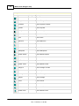
Martin Show Designer Help
Fixture Insert
Inserts a Fixture
Move Beam
B
Allows control of fixtures beams with the mouse
Focus Beam
F
As above, but moves all beams to the same position
Fast Patch
P
Allows you to quickly re-patch the addresses and ID numbers
for all your fixtures.
Move
M
Move an object or fixture
Move Horz.
Move an object or fixture left or right.
Move Vert..
Move an object or fixture up or down
Scale
S
Resize an object using the mouse
Scale Horz.
Resize only up and down
Scale Vert.
Resize only left and right
Scale XYZ
ALT+S
Resize an object in 3D
Rotate Horz. Axis
Rotate an object or fixture in the horizontal axis
Rotate Vert. Axis
Rotate an object or fixture in the vertical axis
Rotate Depth
Axis
R
Rotate an object or fixture in the depth axis
Rotate Two Axis
Rotate an object or fixture in the horizontal and vertical axis
World Axis
Move, Rotate or Scale base on World Axis
Object Axis
Move, Rotate or Scale base on Object Axis
Group
G
Group objects together
Group Axis
ALT+G
Group objects with the picked object axis
Assembly
CTRL+G
Group fixtures and objects together to create a multiple
sources fixture. (Example Bar of 6 Pars)
Subtract
Groups and subtracts the selected object (Only visible at
render time)
Intersect
Groups and keeps only the intersection between the objects
(Only visible at render time)
Attach
Shift+G
Attach Dynamic object Hook to selected object
Un-group
U
Separates grouped objects into the original objects
Zoom
Z
Zoom the camera in and out on current view
© 2015 Martin Professional A/S, Lighthouse Holland
Rev.: 7/10/2015, 11:49 AM
MSD Basic knowledge
Camera Move To/ X
From
Move the camera in and out of current view
Camera Inspect
C
Move the camera around on current view
Camera Move
V
Move the camera up, down, left or right.
Camera Swivel
ALT+V
Point the camera in a different direction
Camera undo
ALT-Z
Undo your last camera move.
Camera redo
ALT-Y
Redo your last camera move, after using undo
9
Select Camera
Select a saved camera position
Full View
Resets camera position and zoom so you can see your whole
scene, on current window
Full view all
Resets camera position and zoom so you can see your whole
scene, on all windows
Insert Object
Insert an Object
Duplicate
ALT+D
Insert a duplicate of the current object
Duplicate Multiple
Insert multiple duplicates of current object
Wire frame
Puts the current window into a wire frame view
Wire frame (Lit)
As above, but with illumination levels as well
Solid
Puts the current view into a solid view
Trace SHADOW
Makes a 3D rendering of the current view, (only in 3D windows)
Fast-Switch to
ShowDesigner
When click the current scene will close from the current
module and re-reopened in the ShowDesigner module
Fast-Switch to
Modeller
When click the current scene will close from the current
module and re-reopened in the Modeler module (if an object
was selected it will be open)
Fast-Switch to 3D
Visualizer
When click the current scene will close from the current
module and re-reopened in the 3D Visualizer module
Fast-Switch to
Paper
When click the current scene will close from the current
module and re-reopened in the Paper module
© 2015 Martin Professional A/S, Lighthouse Holland
Rev.: 7/10/2015, 11:49 AM
10
Martin Show Designer Help
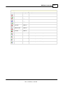
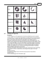
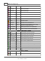
Icons specific to the Modeler module
Icon
Item
Hotkeys
Description
Cube
Insert a Cube
Triangle 4
Insert a Triangle 4 Facets
Pyramid 4
Insert a Pyramid 4 Facets
Cylinder
Insert a Cylinder
Half Cylinder
Insert a Half Cylinder
Quarter Cylinder
Insert a Quarter Cylinder
Cone
Insert a Cone
Half Cone
Insert a Half Cone
Quarter Cone
Insert a Quarter Cone
Sphere
Insert a Sphere
Half Sphere
Insert a Half Sphere
Quarter Sphere
Insert a Quarter Sphere
Toroid
Insert a Toroid
Half Toroid
Insert a Half Toroid
Quarter Toroid
Insert a Quarter Toroid
Triangle 3
Insert a Triangle 3 Facets
Pyramid 3
Insert a Pyramid 3 Facets
Rectangle
Insert a Rectangle
Triangle
Insert a Triangle
Corner
Insert a Corner
Circle
Insert a Circle
Half Circle
Insert a Half Circle
Quarter Circle
Insert a Quarter Circle
© 2015 Martin Professional A/S, Lighthouse Holland
Rev.: 7/10/2015, 11:49 AM
MSD Basic knowledge
Icons specific to the 3D Visualizer module
Icon
Item
Hotkeys
Front View
CTRL+1
Back View
CTRL+2
Left View
CTRL+3
Right View
CTRL+4
Top View
CTRL+5
Bottom View
CTRL+6
3D View
CTRL+0
Description
Isometric SW
Isometric view (from South-West)
Isometric SE
Isometric view (from South-East)
Isometric NE
Isometric view (from North-East)
Isometric NW
Isometric view (from North-West)
© 2015 Martin Professional A/S, Lighthouse Holland
Rev.: 7/10/2015, 11:49 AM
11
12
Martin Show Designer Help
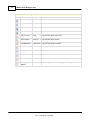
Icons specific to the Paper module
Icon
Item
Hotkeys
Description
Zoom 1:1
Zoom to 1:1 ratio
Zoom Full View
Zoom to full view so the whole document is visible
Zoom In
Zoom inward on the sheet
Zoom Out
Zoom outward on the sheet
Bring To Front
Home
Bring selected object to the front
Move Forward
Page Up
Bring selected object forward
Move Backward
Page Down Bring selected object backward
Send to back
End
Send selected object to the back
Data grid
Display a grid with all information needed…
Re-number Mode
In this mode fixture ID can be renumbered
Patch Mode
In this mode fixture address can be change
Overlapping
address
Mark fixture(s) that have overlapping address range
© 2015 Martin Professional A/S, Lighthouse Holland
Rev.: 7/10/2015, 11:49 AM
MSD Basic knowledge
2.2
Hotkeys
Modeller and Show Designer Hotkeys
Item
Hotkeys
Objects / Fixtures
Move
M
Rotate
R
Scale
S
Scale 3D
ALT+S
Camera
Camera Zoom
Z
Camera In/Out
X
Camera Inspect
C
Camera Pan View
V
Camera Swivel
ATL+V
Camera Undo
ALT+Z
Camera Redo
ALT+Y
Edit
Select All
CTRL+A
De-Select All
SHIFT+ESC
Edit Fixture Layers
Ctrl+F (not in Modeller)
Edit Object Layers
Ctrl+L (not in Modeller)
Properties
ALT+Enter
Delete
DEL
Undo
CTRL+Z
Redo
CTRL+Y
Other
Fast Patch
P
Print
Save
CTRL+S
Jump from window to Window
CTRL+page
Light Mode (toggle)
L
Move beam
B
Focus beam
F
Light Intensity meter
I
Replace Fixture
CTRL+H
© 2015 Martin Professional A/S, Lighthouse Holland
Rev.: 7/10/2015, 11:49 AM
13
14
Martin Show Designer Help
Combine
Group
G
Group Axis
ALT+G
Group Assembly
CTRL+G
Attach
Shift+G
UnGroup
U
Offline Visualizer Shortcuts
File New
Ctrl+N
File Open
Ctrl+O
File Save
Ctrl+S
Edit Fixture Layers
Ctrl+F
Edit Object Layers
Ctrl+L
3D Camera
Ctrl+0
Front Camera
Ctrl+1
Back Camera
Ctrl+2
Left Camera
Ctrl+3
Right Camera
Ctrl+4
Top Camera
Ctrl+5
Bottom Camera
Ctrl+6
View complete scene
Ctrl+7
Camera Undo
Alt+Z
Camera Redo
Alt+Y
Picked Fixture Properties
Alt+Enter
Camera Properties
Alt+Shift+Enter
Normal Screen Mode
F2
Full Screen Mode ( Toolbar's visible )
F3
Max Screen Mode (Only scene visible)
F4
Start current Fast Focus Operation
F
Camera Zoom
Z
Camera In/Out
X
Camera Inspect
C ((Rotate around picked fixture only when
window is in 3D view)
Camera Pan
V
Camera Swivel (rotate camera)
Alt+V (only when window is in 3D view)
Display Timing information
Ctrl+T
Display DirectX memory information
Ctrl+M
Mouse Functions
© 2015 Martin Professional A/S, Lighthouse Holland
Rev.: 7/10/2015, 11:49 AM
MSD Basic knowledge
LMB = Left Mouse Button, RMB = Right
Mouse Button, MMB = Middle Mouse
Button
LMB
Pick objects
LMB + CTRL
Pick objects and keep other selections
LMB + Mouse Drag
Clear selection, Clear Pick, Select all objects
inside rubber band box
LMB + SHIFT + Mouse Drag
Clear selection, Clear Pick, Select all objects
inside and touching rubber band box
LMB + ALT + Mouse Drag
Clear selection Clear Pick, Select all touching
the dragged line
LMB + CTRL + Mouse Drag
Select all objects inside rubber band box
LMB + CTRL + SHIFT + Mouse Drag
Select all objects inside and touching rubber
band box
LMB + CTRL + ALT + Mouse Drag
Select all touching the dragged line
RMB + Mouse Drag
Zoom Rectangle
MMB + Mouse Drag
Camera PAN
Mouse wheel
Zoom on Cursor position
MMB Double Click
Full View for current view
Nudge Functions
Move
Arrows key
Starts with a move of 1 pixel. Holding down the
key will keep moving, slowly accelerating.
SHIFT+Arrows key
Starts with a move of 10 pixels. Holding down
the key will keep moving, slowly accelerating.
Scale
Arrows key
Starts with a move of 1 pixel. Holding down the
key will keep moving, slowly accelerating.
SHIFT+Arrows key
Starts with a move of 10 pixels. Holding down
the key will keep moving, slowly accelerating.
Rotate
Arrows key
Starts with a rotation of 1/10th of a degree.
Holding down the key will keep rotating, slowly
accelerating.
SHIFT+Arrows key
Starts with a rotation of 1 degree. Holding
down the key will keep rotating, slowly
accelerating.
CTRL+Arrows key
Starts with a rotation of 45 degrees. Holding
down the key will keep rotating in steps of 45
degrees.
© 2015 Martin Professional A/S, Lighthouse Holland
Rev.: 7/10/2015, 11:49 AM
15
16
2.3
Martin Show Designer Help
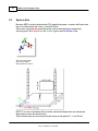
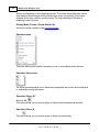
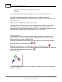
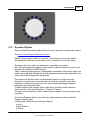
System Axis
Because MSD is a three-dimensional (3D) graphical program, a system with three axes
has to be determined: the X-axis, Y-axis and Z-axis.
These axes represent the spatial horizontal, vertical and depth axis respectively.
In the program, the X-axis is red, the Y-axis is green and the Z-axis is blue.
X is from Left to Right
Y is from Up Down
Z is from Back to Front\
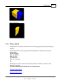
NOTE: If (in case of a window) the horizontal, vertical and depth axes are mentioned,
these axes concern the window axes.
These window axes are not necessarily the same as the spatial X-, Y- and Z-axis.
© 2015 Martin Professional A/S, Lighthouse Holland
Rev.: 7/10/2015, 11:49 AM
MSD Basic knowledge
17
Note: Most CAD systems, use a right-handed coordinate system. However in these
environments the Z axis defines height, not depth. This stems back to 2D CAD systems
where X, Y is the drawing plane. When extended to 3D, Z became the height above the
drawing plane.
In 3D World we tend to look at things like a human normally do ie.: When referring to a
three-dimensional plane, a z-axis refers to the depth of a three-dimensional object.
When referring to the other axis planes, x-axis refers to the horizontal width and y-axis
refers to the vertical height of the object.
2.4
Fast-Switch
Often it is necessary to open a scene already open in one module into another module
In MSD the same file cannot be open in multiple modules at the same time.
Example you are working on a scene and an object from that scene need to be
modified in modeler or a scene in 3D Visualizer need to be open in ShowDesigner for
modification.
The Fast-Switch allow this operation to be done ...well fast...!
Available in the toolbar as well as in the File menu are three items
Fast-Switch to ShowDesigner
When click the current scene will close from the current module and re-reopened in the
ShowDesigner module.
Fast-Switch to Modeller
When click the current scene will close from the current module and re-reopened in the
Modeler module. (if an object was selected it will be open)
Fast-Switch to 3D Visualizer
When click the current scene will close from the current module and re-reopened in the
3D Visualizer module.
Fast-Switch to Paper
When click the current scene will close from the current module and re-reopened in the
Paper module.
© 2015 Martin Professional A/S, Lighthouse Holland
Rev.: 7/10/2015, 11:49 AM
ShowDesigner
Part
III
ShowDesigner
3
ShowDesigner
Menu
Layout
Camera
Fixtures
Objects
Grouping objects and fixtures
Fixture Block
Scene Block
Dynamic Objects
Material and Textures
Rendering
Layers
Cuelist
Dmx Control
Printing
Fast Patch
3.1
Menus
File
Cue
Edit
View
Window
Display Mode
Operation
Camera
© 2015 Martin Professional A/S, Lighthouse Holland
Rev.: 7/10/2015, 11:49 AM
19
20
Martin Show Designer Help
DMX
Settings
Help
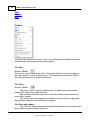
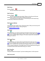
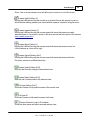
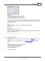
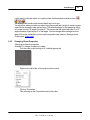
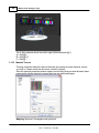
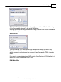
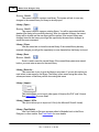
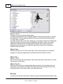
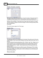
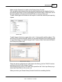
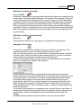
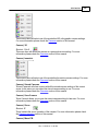
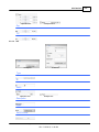
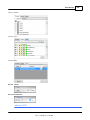
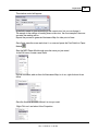
File Menu
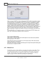
You will use the entries in this menu to open, close and save files, setup the printer, get
information about the program and exit the program.
File | New
Shortcut : Ctrl+N
This menu is used to create a new scene. The system will ask to save any changes to
the current scene if a scene is already open. The new scene will read the file 'Default.
spt' in the spot directory for all the default fixtures.
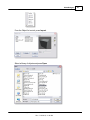
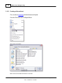
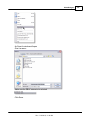
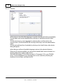
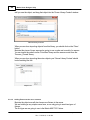
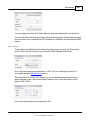
File | Open...
Shortcut : Ctrl+O
This menu is used to open an existing scene. You will be presented with the
standard file dialog in the scenes directory.
After you have selected a scene, the current scene will be closed and the new
scene will be opened.
If the current scene was changed since the last save you will get the opportunity
the save these changes or cancel the open command.
File | Open and Update...
Like the above Open command except that all fixture definitions are fetch into the
Spots folder and replace with the new ones.
© 2015 Martin Professional A/S, Lighthouse Holland
Rev.: 7/10/2015, 11:49 AM
ShowDesigner
21
Example, new fixture definition include new 2D symbols for printing. so to update
scene made with previous fixture definition, use the Open and Update
File | Close
Use this menu item to close the current scene. If the current scene has any unsaved
changes you will get the opportunity to save these before the scene is closed.
File | Save
Shortcut : Ctrl+S
Save is used to save the current scene. If the current scene was never saved
before, you must enter a name for the new scene.
File | Save As...
This menu item is used to give the scene a new name. If you use this option you
must select a new name for the scene. The scene is then saved using this name. Any
subsequent saves of the scene will be done using this name.
File | Export Block...
Use Export Block to save a portion of a scene as a Scene Block or Fixture Block
File | Fast-Switch
Use Fast-Switch to open the current scene into another module. See Fast-Switch
for more details
File | Print Setup...
This option allows you to setup the current printer.
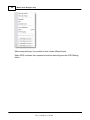
File | Recent files
Here you will find the 4 last saved/opened files. By selecting one of these files
you can open the selected scene.
File | Exit
Shortcut : Alt+F4
This option will shut down the program. If there is a scene open and if this scene
has any unsaved changes you will be asked to save these changes or cancel the
operation.
© 2015 Martin Professional A/S, Lighthouse Holland
Rev.: 7/10/2015, 11:49 AM
22
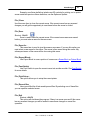
Martin Show Designer Help
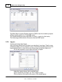
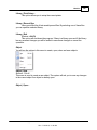
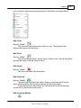
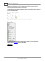
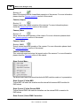
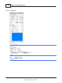
Cue menu
Cue | Select Cue...
This option shows the Cue List.
Cue | Save Cue As...
See Cue List for more details
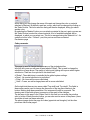
Edit menu
You will use the entries in this menu to delete, copy and insert objects and fixtures, clear
pick or selection, edit layers and switch between 'Light Mode' and 'Normal Mode'.
Edit | Undo
Shortcut : Ctrl+Z
This option will undo the last action (if there is one). The text after 'Undo'
indicates the nature of the last action.
Edit | Redo
Shortcut : Ctrl+Y
This option will redo the last 'undone' action (if there is one). The text after 'Redo'
indicates the nature of the last 'undone' action.
© 2015 Martin Professional A/S, Lighthouse Holland
Rev.: 7/10/2015, 11:49 AM
ShowDesigner
23
Edit | Delete
Shortcut : Ctrl+X
This option will delete the picked object.
Edit | Duplicate
Shortcut : Ctrl+D
This option will copy the picked object. When you click with your left mouse
button inside a window, the copy will be inserted into the scene.
If you keep the mouse button down, you can directly move the inserted copy
around until you release the mouse button.
Edit | Duplicate Multiple
This option will make multiple copies of the picked object. When you click with your left
mouse button inside a window, a dialog will appear.
See Duplicate Object or Fixture
Edit | Insert
This option allows you to insert an object from the object list into the scene. See Object
List for more information about objects. When you click in a window after selecting this
option a list of available objects will appear. The desired object will be inserted after
clicking on it in the list.
Edit | Insert Fixture
This option allows you to insert a fixture from the fixture list into the scene. See Fixture
List for more information about fixtures. When you click in a window after selecting this
option a list of available fixture manufacturers will appear. When you move your mouse
over the desired manufacturer, all available fixtures from that manufacturer will appear.
The desired fixture will be inserted after clicking on it in the list.
Edit | Clear Pick
Shortcut : ESC
This option clears the current pick. If you had something picked, it will be unpicked.
Edit | Deselect All
© 2015 Martin Professional A/S, Lighthouse Holland
Rev.: 7/10/2015, 11:49 AM
24
Martin Show Designer Help
Shortcut : Shift+ESC
This option clears the selection. If you have one or more objects selected, they will be
de-selected.
Edit | Edit Fixture Layers
Shortcut : Ctrl+F
When you select this option, a dialog will appear. See Layers for more details
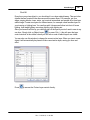
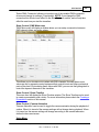
Edit | Edit Object Layers
Shortcut : Ctrl+L
When you select this option, a dialog will appear. See Layers for more details
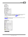
In this dialog, you can edit the object layers. You can edit the name of a layer by clicking
in the left box (layer line will become active), and then clicking in it again. You can then
edit the existing name or enter a new name. You can make one of the layers 'Active'.
This means that any new objects will be placed on that layer. In the 'Visible' column, you
can select which layers are visible or hidden. The 'Active' layer must be visible, because
otherwise, you would not see objects you add to the scene.
Edit | LightMode
This option activates and deactivates the LightMode. When you are working in
LightMode, you can only pick fixtures. All other objects are ignored when you try to pick
something.
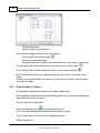
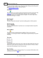
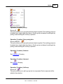
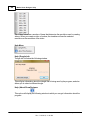
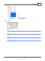
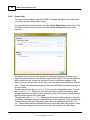
View menu
You can use the entries in this menu to view or hide the toolbars holding the buttons, the
different lists and the status bar at the bottom of the main window. If an item is visible a
check mark will be displayed in front of the menu item.
View | Toolbars
© 2015 Martin Professional A/S, Lighthouse Holland
Rev.: 7/10/2015, 11:49 AM
ShowDesigner
25
This menu is used to show or hide the toolbars. For an overview of all the buttons in the
toolbars you can look at the Icon topic.
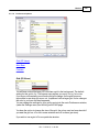
View | Object list...
This option shows the Object List window. In this window you can delete, rename and
import objects. In a new scene this list will be initially empty.
View | Fixture list...
This option shows the Fixture List window. In this window you can delete, rename and
import fixtures.
In a new scene this list will contain all fixture reads from the 'Default.spt' file in the spot
directory. See this Topic to change this behavior.
View | Material list...
This option shows the Material List window. In this window you can edit, copy, import,
delete and create new materials. In a new scene this list will be initially empty.
View | Cue list...
This option shows the Cue List window. In this window you can edit, delete and create
new cues. In a new scene this list will be initially empty.
View | Status Bar
This menu is used to show or hide the status bar.
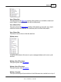
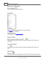
Window menu
You will use the entries in this menu to open or arrange windows and to save or print
windows.
© 2015 Martin Professional A/S, Lighthouse Holland
Rev.: 7/10/2015, 11:49 AM
26
Martin Show Designer Help
Window | New 2D window
This option opens a new 2D window.
Window | New 3D window
This option opens a new 3D window.
Window | Cascade
This option will arrange all open windows to be all the same size, stacked one on top of
another.
Window | Tile
This option will arrange all open windows to be tiled side by side, so all windows will be
totally visible.
Window | Arrange Icons
This option will arrange all icons at the bottom of the main window.
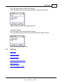
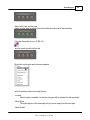
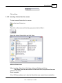
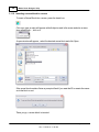
Window | Save as Bitmap...
This option allows you to save a window as a Windows bitmap (BMP) or a jpeg image
(JPG).
Window | Print...
Shortcut : Ctrl+P
This option allows you to print a window. The print will always be in wireframe mode.
See Printing in ShowDesigner Module for more details
Window | Print Preview
This option allows you to preview how a window will be printed.
See Printing in ShowDesigner Module for more details
Window | (Opened windows)
Here you will see how many windows you have open and which is active. You can
activate a specific window by choosing its menu item.
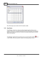
Display Mode menu
© 2015 Martin Professional A/S, Lighthouse Holland
Rev.: 7/10/2015, 11:49 AM
ShowDesigner
27
This menu allows you to select the display mode of a window. It gives you a range of
representations of a scene.
See Display Mode for more details
Display Mode | Render
Display Mode, Render menu
This menu will only be available in a 3D window. It allows you to realistic render your
scene, taking into account lighting, reflection, shadows, smoke etc.
See Rendering for more details
Display Mode | Render | Start
The start option will start the rendering of the scene.
Display Mode | Render | Hold
The Hold option will temporarily stop rendering the window. This might be useful if you
are rendering a complex scene. By setting the rendering on hold, you get more time to
do other things (in this application or another). This option is only available if you are
currently rendering in the window.
Display Mode | Render | Resume
The Resume option will resume rendering a window, which was previously stopped by
using the Hold option. This option is only available if the window is currently in a 'hold
rendering' mode.
Display Mode | Render | Exclusive
The Exclusive option is a special case of the Start option. The exclusive option will also
start rendering a window, but if you choose this option, the ShowDesigner application
© 2015 Martin Professional A/S, Lighthouse Holland
Rev.: 7/10/2015, 11:49 AM
28
Martin Show Designer Help
will turn its full attention to the rendering process. This means that nothing else can be
done with the ShowDesigner until the rendering process is completed. It can not be
stopped! So be very careful to use this option. The only advantage of this way of
rendering is that it is faster.
Display Mode | Render | Create Render file
Use this to create a render for the Fast Net-Render
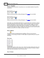
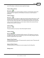
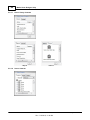
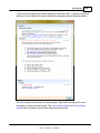
Operation menu
This menu allows you to start an operation on one or more objects and/or fixtures.
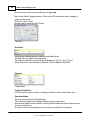
Operation | Move menu
The Move operations allow you to interactively manipulate the position horizontally and/
or vertically by moving the mouse.
Operation | Move | XY
Shortcut : M
This option allows you to move an object or fixture both horizontally and vertically.
Operation | Move | X
This option allows you to move an object or fixture only horizontally.
© 2015 Martin Professional A/S, Lighthouse Holland
Rev.: 7/10/2015, 11:49 AM
ShowDesigner
29
Operation | Move | Y
This option allows you to move an object or fixture only vertically.
Operation | Rotate
The Rotate operations allow you to interactively manipulate the orientation of an object
or fixture.
Operation | Rotate XY
Shortcut : R
This option allows you to rotate an object or fixture around both the horizontal and
vertical axis.
Operation | Around Horizontal
This option allows you to rotate an object or fixture around the horizontal axis.
Operation | Around Vertical
This option allows you to rotate an object or fixture around the vertical axis.
Operation | Around Depth
This option allows you to rotate an object or fixture around the depth axis.
Operation | Scale
© 2015 Martin Professional A/S, Lighthouse Holland
Rev.: 7/10/2015, 11:49 AM
30
Martin Show Designer Help
The Scale operations allow you to interactively manipulate the size of an object.
Operation | Scale | Horizontal
Shortcut : S
This option allows you to scale an object horizontally.
Operation | Scale | Vertical
This option allows you to scale an object or vertically.
Operation | Scale | 2D
This option allows you to scale an object horizontally and vertically.
Operation | Scale | 3D
This option allows you to scale an object uniformly by scaling the whole object by the
same amount.
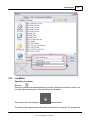
Operation | Lux meter
Shortcut: I
This option activates and deactivates the Lux meter.
See Lux Meter for more details...
Operation | Fixture Operation |
© 2015 Martin Professional A/S, Lighthouse Holland
Rev.: 7/10/2015, 11:49 AM
ShowDesigner
31
The Fixture operations allow you to manipulate one or more fixtures.
Operation | Fixture Operation | Move Beam
This option allows you to move the focus point of one or more fixtures, relative to its or
their position(s).
Operation | Fixture Operation | Focus Beam
Shortcut: F
This option allows you to focus one or more fixtures on the point you click, and then drag
the focus.
Operation | Fixture Operation | Look through fixture...
This function allow you to see as if you were inside the fixture looking out by the lens.
See Look Through Fixture topic for more details
Operation | Fixture Operation | Fast patch
Shortcut: P
This option allows you to patch fixtures using the mouse
See Fast-Patch for more details
Operation | Fixture Operation | Beam Hidden
This option allows you to hide/show the beam of the picked fixture.
See Preferences Options for more details on this
Operation | Fixture Operation | Replace Fixture...
Shortcut: CTRL+H
© 2015 Martin Professional A/S, Lighthouse Holland
Rev.: 7/10/2015, 11:49 AM
32
Martin Show Designer Help
This option allows you to replace a fixture by another fixture. The fixture will have the
same position, patch address and focus point. Other settings will be read back from
DMX.
See Replace Fixture for more details
Operation | Alignment menu
Operation | Alignment | Align Chain
This option allows you to align two or more selected objects in a chain like way.
See Align for more details
Operation | Alignment | Align...
This option allows you to align one or more selected object(s) to the active (picked)
object. When you select this option, a dialog will appear.
See Align for more details
Operation | Combine menu
Operation | Combine | Group
Shortcut: G
This option allows you to group the selected objects together. The resulting group can
be treated as a single object from then on. Such a group can always be split again by
picking it and selecting the 'UnGroup' operation.
Operation | Combine | Group using Axis
Shortcut: ALT+G
© 2015 Martin Professional A/S, Lighthouse Holland
Rev.: 7/10/2015, 11:49 AM
ShowDesigner
33
This option allows you to group the selected objects together. The resulting group can
be treated as a single object from then on. Such a group can always be split again by
picking it and selecting the 'UnGroup' operation.
Operation | Combine | Assemble
Shortcut: Ctrl+G
Assembly grouping is similar to normal grouping except that fixtures in the group are still
accessible individually.
A good example of an assembly would be a bar of 4 PARs
Operation | Combine | Attach
Shortcut: Shift+G
Use Attach to link Dynamic Objects with other objects.
See Dynamic Object for more details...
Operation | Combine | Subtract
See Subtractive Grouping
Operation | Combine | Intersect
See Intersect Grouping
Operation | Combine | UnGroup
Shortcut: U
This option allows you to split a group into its components. Each component will be
added to the selection.
Operation | Turn Off Operation
Shortcut: Spacebar
This option turns off all current operation.
Camera Menu
© 2015 Martin Professional A/S, Lighthouse Holland
Rev.: 7/10/2015, 11:49 AM
34
Martin Show Designer Help
This menu allows you to manipulate the camera of a window.
See Camera for more details
Camera | Properties
For information on the camera properties
Camera | Full View
Shortcut: Double click middle mouse button
This option will try to adjust the camera so that the entire scene will be visible in the
current view.
Camera | Full View All
This option will try to adjust the camera so that the entire scene will be visible in all
views.
Camera | Zoom
Shortcut: Z
This option allows you to interactively zoom in/out. In 2D windows, the scale will change
and in 3D windows, it will be the camera angle that changes.
Camera | Move To/From
Shortcut: X
This option allows you to move the camera to and from. In 2D windows, this does the
same as the 'Zoom' operation. In 3D windows, the camera is moved forwards or
© 2015 Martin Professional A/S, Lighthouse Holland
Rev.: 7/10/2015, 11:49 AM
ShowDesigner
35
backwards.
Camera | Inspect
Shortcut: C
This option allows you to inspect an object by moving the camera around a point. In 2D
windows this can only be done if you have an active (picked) object. The camera will
move around the center of the object. In 3D windows the camera will move around the
center of an active object if there is an active object, otherwise the camera will move
around the focus point of the camera.
Camera | Move
Shortcut: V
This option allows you to pan up, down, left and right the camera.
Camera | Swivel
Shortcut: Alt+V
This option allows you to look around with the camera. In 2D windows, you can move
around then view plane, and in 3D windows you can look around by tilting the camera
from left to right and from top to bottom.
Camera | Save Camera...
This option allows you to save a 3D camera position, giving it a name. The camera will
be stored with the scene file.
Camera | Delete Camera...
This option allows you to delete one or more cameras (from this scene file).
DMX menu
You will use the entries in this menu to select and setup a DMX driver and to change
DMX input/output options.
See DMX for more details
DMX | Follow
© 2015 Martin Professional A/S, Lighthouse Holland
Rev.: 7/10/2015, 11:49 AM
36
Martin Show Designer Help
The follow option will turn on/off the follow mode. If the follow mode is active, The
program will be sampling the incoming DMX and update the stage settings accordingly,
until you turn the follow mode off.
DMX | Snapshot
The Snapshot option will sample the incoming DMX once and update the stage settings
accordingly.
DMX | Setup Driver...
This option allows you to change the settings of the current driver. What kind of settings
(if any) are available depends on the active DMX driver.
DMX | Select Driver...
This option allows you to select which of the installed DMX drivers you want to use. If you
select another driver, it will be used the next time you run the program. In other words,
you have to exit and restart the program to have the change of DMX driver take effect.
DMX | Motor Map...
This option allows you to patch Dynamic Objects to DMX channel.
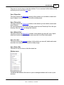
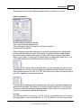
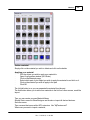
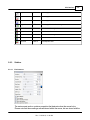
Settings menu
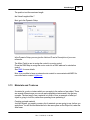
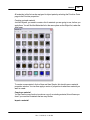
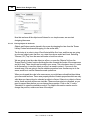
This menu allows you to adjust the appearance and preferences.
Settings | Main Background
This option allows you to change the appearance of the background of the main
application window.
See settings for more details
Settings | Window color
This option allows you to change the background color of the 2D-and 3D windows.
See settings for more details
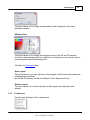
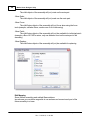
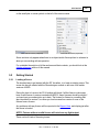
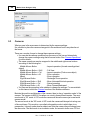
Settings | Preferences
In the preferences dialog you can set your preferences. Some are local (apply only to
© 2015 Martin Professional A/S, Lighthouse Holland
Rev.: 7/10/2015, 11:49 AM
ShowDesigner
37
the ShowDesigner module), some are global (they may apply to all Martin
ShowDesigner modules). The preferences are arranged into groups, with each it's own
page (page). Each page ('Render Settings', 'Snap', 'Grid', 'Units', 'Detail', 'Gamma',
'Auto Save', 'Paths' and 'DirectX driver') will be explained next.
Render Settings page
See Settings for more details
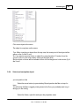
Help Menu
Help | Contents
Shortcut : F1
This option will display this help text.
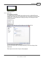
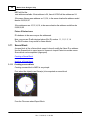
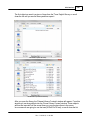
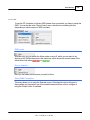
Help | About ShowDesigner...
This option will display a window in which you can get information about the program. By
clicking on the info button you will see information about the current installed version, the
installation date, the serial number of the program and the name with which the program
was installed. By clicking again on the (now 'Version') button, you
3.2
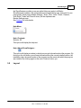
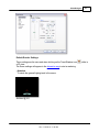
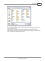
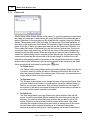
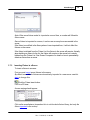
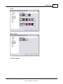
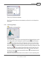
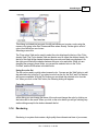
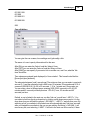
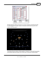
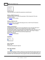
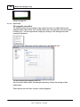
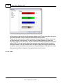
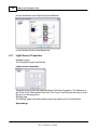
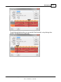
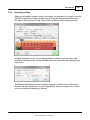
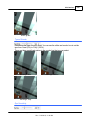
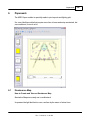
Layout
.
© 2015 Martin Professional A/S, Lighthouse Holland
Rev.: 7/10/2015, 11:49 AM
38
Martin Show Designer Help
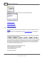
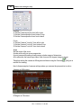
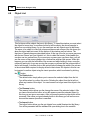
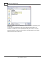
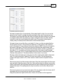
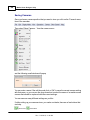
The application window has a menu bar, a status bar, toolbar's, 2D windows and 3D
windows.
The menu bar will be covered in Menu the toolbar's in MSD Icons, 2D windows and 3D
windows in Window Management.
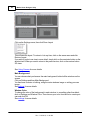
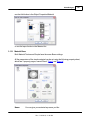
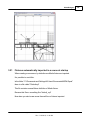
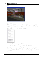
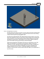
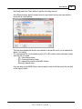
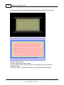
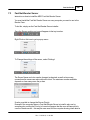
To build a similar layout as above, simply insert 3 2D views and 1 3D view.
From window menu click Tile.
Set the 2D view one as TOP, one as Left and one as Front
In each view, set the Spot Beam Properties to Never
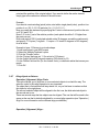
Then in the menu Settings, click on Store Layout.
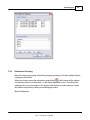
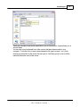
3.3
Window Management
The program has 2 types of windows, namely 2D windows and 3D windows.
Each window has its own capabilities, although many are available in both.
You can not change one type of window into the other, but you can open as many
windows of both types as you like.
(Opening a window can be done by selecting 'New 2D window' or 'New 3D window'
from the menu (see 'Window Menu ').
Both types of windows are further explained in the following sections.
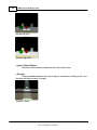
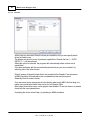
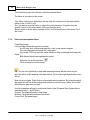
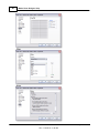
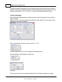
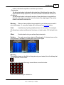
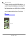
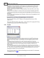
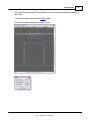
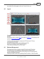
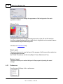
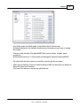
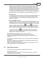
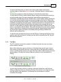
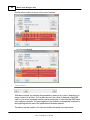
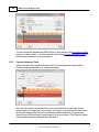
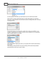
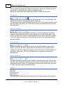
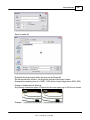
2D Windows
2D windows give you an orthographic view of your scene. You can work in one of six
© 2015 Martin Professional A/S, Lighthouse Holland
Rev.: 7/10/2015, 11:49 AM
ShowDesigner
39
views, namely Front, Back, Left, Right, Top and Bottom.
You can change between these views by clicking one of the 'Camera buttons' in the
top of a 2D window. By clicking on the current (down) camera button, the position
and scale of the camera will be adjusted so the entire scene will be visible. If only a
part of the scene is visible (when you are zoomed in) you can pan through the scene
with the vertical and horizontal scrollbars at the right and bottom of the window. You
can also hold the middle mouse button and drag the mouse around to pan up, down,
left and right
The 2D window also has a grid to enhance orientation in the object. The size and
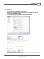
color(s) of the grid can be set in Grid settings
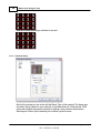
In the 2D camera properties dialog of a 2D window you can set the camera
position, the scale and if the grid should be visible in this view.
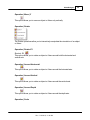
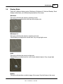
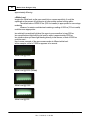
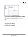
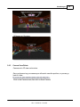
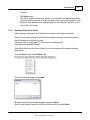
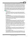
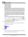
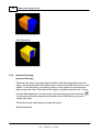
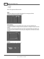
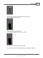
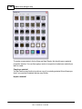
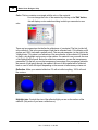
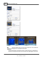
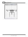
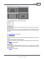
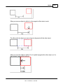
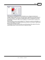
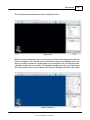
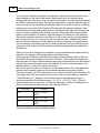
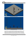
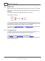
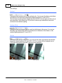
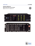
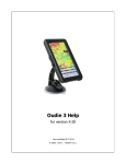
It can be viewed in wireframe mode or solid mode
Wireframe
Solid
© 2015 Martin Professional A/S, Lighthouse Holland
Rev.: 7/10/2015, 11:49 AM
40
Martin Show Designer Help
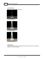
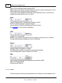
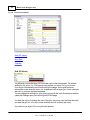
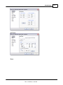
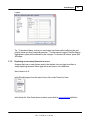
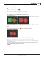
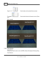
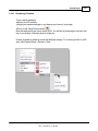
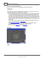
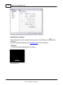
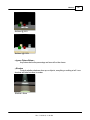
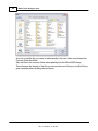
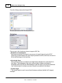
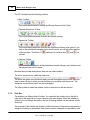
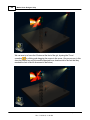
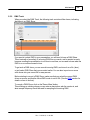
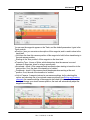
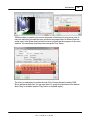
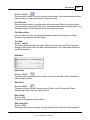
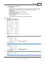
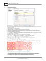
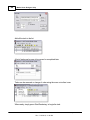
3D Windows
3D windows give you a perspective view of your scene. Here you can view the scene
from any point and with different camera angles. The 3D window has some features the
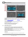
2D window has not:
You can use the 'Render' display mode to calculate a realistic image.
You have an inspect mode, which will rotate your camera around the Y-axis of the
scene. You can start and stop the inspect mode by clicking the right mouse button in
a 3D window and selecting 'Other', 'Inspect Object' in the appearing context menu.
In the 3D camera properties dialog of a 3D window you can set the camera
position, the focus point (the point you are looking at) and the camera angle.
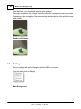
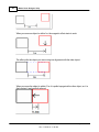
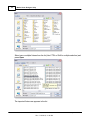
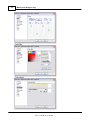
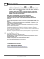
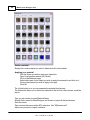
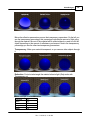
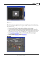
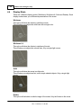
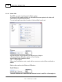
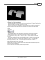
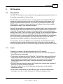
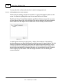
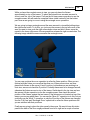
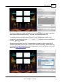
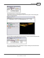
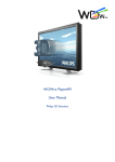
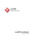
It can be viewed in wireframe mode or solid mode
Wireframe
© 2015 Martin Professional A/S, Lighthouse Holland
Rev.: 7/10/2015, 11:49 AM
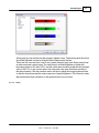
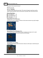
ShowDesigner
41
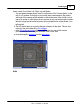
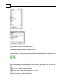
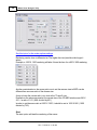
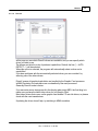
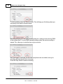
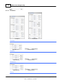
Solid
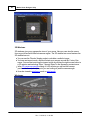
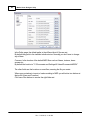
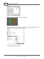
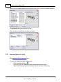
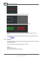
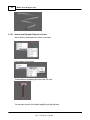
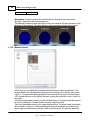
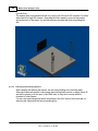
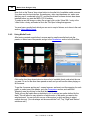
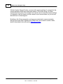
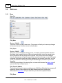
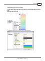
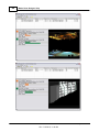
Using multiple windows
So far we have only had one window open. It is possible to open up as many windows
as you like at the same, each one viewing your scene from a different angle. To get you
started a simple 4 window set will do.
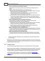
Click on the Window menu, then click on New 2D Window
·
Repeat this process so you have 3 windows open
·
Click on the Window menu again and click on New 3D Window
You should now have 4 windows open. Using the mouse you can move and resize the
windows until they are laid to your satisfaction. To make it easier, open the Window
menu again and click on Tile. You now need to save this setup, so you can go back to it
again in the future.
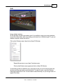
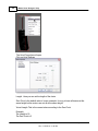
© 2015 Martin Professional A/S, Lighthouse Holland
Rev.: 7/10/2015, 11:49 AM
42
Martin Show Designer Help
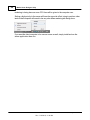
Click on the Settings menu, then click Store Layout
This will save the layout. To return to it at any time, click on the same menu and click
Restore Layout.
If you wish to look at one view in more detail, simply click on the maximize button on the
window itself. When you want to return to the previous view, click on the restore button.
2D views
See Using Camera for more details
Main Background
You can choose what you have as the main background, behind all the windows on the
screen.
Click on Settings and then Main Background.
You then have a choice of nothing, using the main windows image or setting your own
image.
See settings for more details
Window Color
To change the color of the background in each window, to something other than black,
click on Settings and Window Color. Then choose your color from the list or create your
own and click OK
See settings for more details
© 2015 Martin Professional A/S, Lighthouse Holland
Rev.: 7/10/2015, 11:49 AM
ShowDesigner
3.4
43
Display Mode
There are 4 different display modes (Wireframe, Wireframe lit, Solid and Render). Each
display mode shows you a different representation of the scene.
Wireframe
This option will show the objects in wireframe mode.
This will show your objects as solid lines with a single color.
Wireframe Lit
This option will show the objects in wireframe lit mode.
This will show your objects as colored lines, lit by a single light source.
Solid
This option will show the scene in solid mode.
This will show your objects as fast, solid, simple shaded objects, lit by a single light
source.
Render
This option will calculate a realistic image of the scene, lit by the fixtures in the scene
© 2015 Martin Professional A/S, Lighthouse Holland
Rev.: 7/10/2015, 11:49 AM
44
Martin Show Designer Help
(with their fader, iris, zoom angle gels and gobo settings).
During the calculation of the image, shadows, reflections, transparency and even smoke
can be taken into account.
Depending on the complexity of the scene and the selected options, this calculation may
take a while.
Render with Smoke
3.5
Settings
Various settings that can be change to tailor the MSD to your need.
From the menu click on Settings
Main Background
© 2015 Martin Professional A/S, Lighthouse Holland
Rev.: 7/10/2015, 11:49 AM
ShowDesigner
45
This option allows you to change the appearance of the background of the main
application window.
Window Color
This option allows you to change the background color of the 2D-and 3D windows.
Use this to change background form a dark color to a light color or vice-versa to have a
contrast between objects and background.
Click here for Preferences help
Store Layout
This option allows you to save the layout of the program. It will store positions and sizes
of the application windows,
the 2D and 3D windows, and the lists (Object, Fixture, Material and Cue).
Restore Layout
This option allows you to restore the layout of the program by loading the saved
settings.
3.5.1
Preferences
From the menu Settings, click on preferences
© 2015 Martin Professional A/S, Lighthouse Holland
Rev.: 7/10/2015, 11:49 AM
46
Martin Show Designer Help
Render Settings
Object Snap
Units
Gamma
Paths
DirectX Driver
Language
Options
[****]
3.5.1.1
Rendering Default Settings
To set the default Rendering settings, from the menu Settings, click on Preferences
click on Render Settings
© 2015 Martin Professional A/S, Lighthouse Holland
Rev.: 7/10/2015, 11:49 AM
ShowDesigner
47
Default Render Settings
These settings are the one used when clicking on the Trace/Shadow icon
a 3D view
The Same settings will appear in the alternative way to start a rendering.
Ambient
Controls the general lighting level in the scene.
Ambient @ 0%
© 2015 Martin Professional A/S, Lighthouse Holland
Rev.: 7/10/2015, 11:49 AM
while in
48
Martin Show Designer Help
Ambient @ 50%
Ambient @ 100%
Ignore Fixture Below...
Any fixtures below the percentage set here will not be shown
Shadow
Controls whether shadows show up on objects, everything or nothing at all. Less
shadows will take less time to render.
Shadow = None
© 2015 Martin Professional A/S, Lighthouse Holland
Rev.: 7/10/2015, 11:49 AM
ShowDesigner
49
Shadow = On Object (smoke rays goes through objects)
Shadow = Always
Smoke
Turns smoke or haze in the atmosphere on or off. Smoke on slows down the rendering
process.
No Smoke
With Smoke
© 2015 Martin Professional A/S, Lighthouse Holland
Rev.: 7/10/2015, 11:49 AM
50
Martin Show Designer Help
Smoke Density
Controls the level of smoke in the scene.
Smoke Density @ 1
Smoke Density @ 15
Smoke Density @ 30
Smoke Type
Controls whether the smoke is evenly spread out, like a haze machine or in puffs like it
might be from a smoke machine.
© 2015 Martin Professional A/S, Lighthouse Holland
Rev.: 7/10/2015, 11:49 AM
ShowDesigner
51
Smoke Type: Haze @ 1
Smoke Type: Haze / Puff @ 15
Smoke Type : Puff @ 30
Anti-Aliasing
Anti-Aliasing is a process that soften the edges in a rendering process. It does take a
little more time, but makes rendering more natural.
Without Anti-Aliasing
© 2015 Martin Professional A/S, Lighthouse Holland
Rev.: 7/10/2015, 11:49 AM
52
Martin Show Designer Help
approximately-Aliasing
White Level
Imagine the White level as the eyes sensitivity or camera sensitivity. It could be
explained as the amount of light require to have a white surface looking white...
The default value of 2200.00 lux (200 foot candle) is appropriate for more stage
rendering
However, for exterior architectural rendering a setting of 800 lux (75 foot candle)
could be more appropriate...
In a relatively low ambient light level, the eyes is more sensitive, let say 500 lux
In a normal ambient light level the lux level for white is approximately 2200 lux
In a situation when you have light blasting directly in the camera, a level of 5000 lux
could be used...
Here's some example of the same scene render at different white level.
In this example, a level of 1000 lux appears to be normal.
White Level @ 5000
White Level @ 2200 (Default)
White Level @ 1000
White Level @ 500
© 2015 Martin Professional A/S, Lighthouse Holland
Rev.: 7/10/2015, 11:49 AM
ShowDesigner
53
White Level @ 100
3.5.1.2
Object Snap
The magnetic snap effect.
The default settings for the magnetic snap system are set so an object will become
magnetic when it gets within 1m of another object and it will snap the to the object when
it's within 0.1m. You can adjust these settings by clicking on the Settings menu and
opening Preferences.
Then click on the Snap page and the settings are in the Magnetic box.
You can even turn the magnetic effect off.
Here is how the effect works, this example assumes you leave the settings at their
default value.
When objects are more than 1m apart, nothing happens.
© 2015 Martin Professional A/S, Lighthouse Holland
Rev.: 7/10/2015, 11:49 AM
54
Martin Show Designer Help
When you move an object to within 1m, the magnetic effect starts to work.
The effect pulls the object you are moving into alignment with the other object.
When you move the object to within 0.1m it is pulled up against the other object, so it is
flush against it and perfectly aligned.
© 2015 Martin Professional A/S, Lighthouse Holland
Rev.: 7/10/2015, 11:49 AM
ShowDesigner
3.5.1.3
55
System Untis
The MSD can work in both Imperial or Metric system.
At any point in the creation process you can switch from one system to the other, call
values will be converted as indicated
For each settings the precision (number of decimal digit) can be set.
Distance
Set the unit values to enter position and dimensions of objects
Distance: Meters, Millimeters, Inches or Feet & Inches.
Imperial value must be enter as follow
1'2" = 1 foot 2 inches
When using Feet&Inches, enter a value with no comma or quote will be considered as
inches
Metrics value can be set in Meters or Millimeters
Small Distance
The small distance unit is used when the distance to enter is small like in the margins in
© 2015 Martin Professional A/S, Lighthouse Holland
Rev.: 7/10/2015, 11:49 AM
56
Martin Show Designer Help
paper or the line thickness when importing DXF.
When using metric units the normal distance unit is meter, but this would result in a lot of
0,00x numbers when dealing with these small sizes.
To make this more readable we added the extra small distance unit, so the user can
display these small numbers in mm or inches.
Angle
Angle: Degrees (360°), Radials (2p) or Gradients (400°).
The most common settings for Angle is Degree.
In some situation Gradient or Radial degree can be chosen.
See Formulas for more details in angle types
Light
Light: Lux or Foot-candle.
In MSD, it is possible to calculate the amount of light at a specific point on a surface.
The light intensity can be displayed as Lux or FootCandle.
Weight
Weight: Grams, Kilograms or Pounds.
In the Paperwork module, it is possible to see the fixture weight.
It can be displayed as Grams, Kilograms or Pounds.
DMX
Various ways of displaying DMX addresses are possible in MSD
Offset is the DMX address.
Universe is the DMX link
3.5.1.4
Gamma
The Gamma page contains global preferences for the way your monitor displays colors
© 2015 Martin Professional A/S, Lighthouse Holland
Rev.: 7/10/2015, 11:49 AM
ShowDesigner
57
In this page you can set the way the program adjusts colors. Determining how the colors
should be adjusted is done by using the three sliders and/or values.
There are four color sections, one for red, green, blue and gray each. Every section has
an outer area and a center area. The outer area is a dithered pattern of pixels with
luminance values of 0% and 100%, and the center area contains pixels with a luminance
value of 50%. So to get correct values, the inner and outer area should be optically of
the same intensity. Use the scrollbar and/or edit box to adjust the image's gamma level
so that the inner areas and the outer areas are of equal brightness. The correction value
that synchronizes their luminance is the gamma level of your monitor.
3.5.1.5
Paths
© 2015 Martin Professional A/S, Lighthouse Holland
Rev.: 7/10/2015, 11:49 AM
58
Martin Show Designer Help
In the Paths page, the default paths to the different kind of files are set.
By default they point to the installed subdirectories. Normally you don't have to change
any of them.
Common: Is the location of the default MSD files such as fixtures, textures, demo
scenes etc...
By default the location is "C:\Documents and Settings\All Users\Documents\MSD4"
The other fields are the locations on user files, meaning the file you create.
When open a window to import or load something is MSD you will notice two buttons at
the top left (User and Common)
Click one of the buttons to access the right folder set.
© 2015 Martin Professional A/S, Lighthouse Holland
Rev.: 7/10/2015, 11:49 AM
ShowDesigner
59
As a rule, put all the file you create or add manually to the user folder set and leave the
Common folder as default.
Only add files to the common folder when updating from the official MSD library.
This will ensure the integrity of the files you use and also avoid that your modified library
gets overwritten when updating the new library.
© 2015 Martin Professional A/S, Lighthouse Holland
Rev.: 7/10/2015, 11:49 AM
60
3.5.1.6
Martin Show Designer Help
DirectX
In this page you see which DirectX drivers are available, and you can specify which
driver you want to use.
The drivers are listed in order of preferred capabilities. Default, the first ('--- AUTO
DETECT ---') will be selected.
When this option is selected, the program will automatically select a driver on its
capabilities.
If you have problems with the automatically selected driver, you can override it by
selecting one of the other drivers.
DirectX means all graphical calculation are handled by the Graphic Card processor
In MMX Emulation, the calculation are now handled by the main processor.
Generally DirectX mode is faster.
If you encounter some strange result in the display when using MSD, the first thing is to
make sure you have the latest video driver for you Graphic Card.
Most video drivers that comes on the graphic card bundle CD are old drivers, so please
check with the card manufacturer.
If updating the driver doesn't help, try switching to MMX emulation.
© 2015 Martin Professional A/S, Lighthouse Holland
Rev.: 7/10/2015, 11:49 AM
ShowDesigner
3.5.1.7
61
Language
In this page you see which help language is currently selected (and which are available).
You can select one from the available list by clicking on it and then press the 'select'
button.
You can remove one or more languages by selecting them, and then click on the
'remove' button. (On Windows2000 this can only be done by a user with administrative
rights)
You can (re)install help files (if available) by clicking on the 'Install' button, after which a
dialog will appear.
In this dialog you will see all available language versions in the selected directory.
If there are no versions available, you can use the 'manual folder' button to browse to a
directory which does contain a help version.
On the ShowDesigner CD, the folder you need is 'D:\manuals' (if D is your CDROM
drive). From the available list you can install one or more versions by checking the
checkbox in front of them, and then click OK.
© 2015 Martin Professional A/S, Lighthouse Holland
Rev.: 7/10/2015, 11:49 AM
62
3.5.1.8
Martin Show Designer Help
Preferences Options
Grid (2D Views)
Auto Save
Features
Grid (2D Views)
You will have noticed that every 2D view has a grid in the background. The default
setting for this grid is 1m. This means every square you see is 1m by 1m in size.
If you zoom out eventually you will notice the grid change. As the grid becomes
impossible to use when you zoom out, it replaces it with a larger grid. It also changes
the color to you know this has happened.
You can change the settings for your grid by going into the main Preferences window,
(under the Settings menu) and clicking on the Grid page.
You have the option to change the size of the grid, the colors used and even decide if
you want the grid on, off or on in some windows and off in others (per view).
If you wish to turn a grid off in one particular window:
© 2015 Martin Professional A/S, Lighthouse Holland
Rev.: 7/10/2015, 11:49 AM
ShowDesigner
63
Ensure you have set the main preferences to 'per view'
Back to the Show Designer window, Click on the 2D window you wish to change, to
make sure it's active
Press Alt + Shift + Enter
Uncheck the box that says Grid Visible
Click OK
Auto Save
When set on a backup scene is saved at specified interval.
The back files are place is the User folder
The temporary file will look something like 'Backup 05_29_00 14_46_20.scn',
which means its a Scene backup, created at 14:46 on May the 29th 2000.
Features
Toolbar Style:
Toolbar Resolution:
24 Pixels are the new icon style, it's always possible to revert to the Classic icon...
Operation Mode:
The choices are Normal or Bounding box
This is the way objects are displayed while moving a camera view
In Normal the objects remain visible, bounding box will make the object disappear and
show a wireframe box
for slower video card bounding box can be use to accelerate the movement
© 2015 Martin Professional A/S, Lighthouse Holland
Rev.: 7/10/2015, 11:49 AM
64
Martin Show Designer Help
Operation Toggle
The choices are Toggle or Keep Active
In toggle mode, every time you press an hotkey such as M for move, the operation will
be toggled (on or off)
In Keep Active mode, pressing a hotkey while this operation is already selected, the
operation remain active.
Use the Spacebar or the Icon
3.6
to turn off the current operation.
Camera
Camera on the Show Designer works very much like a camera in real world
You can move it, change where it's looking at and modify it's zoom.
Camera properties can be change using the mouse or can also be change in the
Camera properties window
Camera operation can be choose from the Camera Menu...
...Or from the Camera Toolbar
You can view a 3D window from almost any angle you like. You have 5 camera
movements you can use:
Camera Zoom [Hotkey Z]
Holding the LMB and moving the mouse up or down will zoom the camera in and out.
© 2015 Martin Professional A/S, Lighthouse Holland
Rev.: 7/10/2015, 11:49 AM
ShowDesigner
65
Zoom Like on a real camera, zoom will allow you to zoom in or out of the scene
Camera In/Out [Hotkey X]
Holding the LMB and moving the mouse up or down will move the camera in and out.
Would be like walking towards your scene with the camera, instead of using the zoom
Camera Inspect [Hotkey C]
Holding the LMB and moving the mouse around will move the camera around a
selected object or if no select is made, it will move around the focus point of the camera
(see camera properties)
Camera Move [Hotkey V]
Holding the LMB and moving the mouse around will move the camera in and out.
Lift the camera up, down, left or right
Camera Swivel [Hotkey Alt+V]
Holding the LMB and moving the mouse around will move the camera direction
Point your camera in a different direction
Camera Undo [Hotkey Alt+Z]
Undo the last Camera change in the selected view
Camera Redo [Hotkey Alt+Y]
Redo the last Camera Undo in the selected view
Full View [Hotkey Ctrl+7]
Zoom the Camera to fully see the scene of the current view
Full View All
Zoom the Camera to fully see the scene of all views
Camera Selection (only in 3D window)
Press the down arrow and select a saved camera view
© 2015 Martin Professional A/S, Lighthouse Holland
Rev.: 7/10/2015, 11:49 AM
66
Martin Show Designer Help
Or Press the icon and select the camera from the following window
Camera Properties
Save a Camera View
Delete a Camera View
3.6.1
Camera Properties 2D
In Show Designer, there are two type of Cameras; The one for 2D view and the one for
3D view
Camera can be move manually with the mouse(see Using Camera) or edited with
values.
Every 2D window has six view buttons across the top. These can be used to view your
scene from any of the 6 directions:
You can use the Zoom button and drag the mouse to zoom in and out. The mouse wheel
will also do this, except it will zoom in on what ever the mouse is currently pointing at.
You can use the Camera Move button and drag the mouse to move the view around.
The middle mouse button will also do this.
Camera Properties can be access in three ways
-With the hotkey SHIFT+ALT+ENTER
-From the right-click menu on a view
-From the menu Camera
2D Camera Properties
© 2015 Martin Professional A/S, Lighthouse Holland
Rev.: 7/10/2015, 11:49 AM
ShowDesigner
67
Position
X: Set the Camera position form left to right
Y: Set the Camera position form bottom to top
Z: Set the Camera position form front to back
Note: If you are on a Top View for example, only the X and Z need to be set. But make
sure the Y value is higher then the maximum height of the scene, otherwise part of the
scene will be clipped.
Scale
Set the number of unit that 1 unit on screen represent in real life
Example 1:150
Grid Visible
When checked, a grid will be visible.
However, if the grid is not showing, probably the general grid settings is set to Never in
the Setting/Preferences/Grid
-----------------------------------------------------
3.6.2
Camera Properties 3D
In Show Designer, there are two type of Cameras; The one for 2D view and the one for
3D view
Camera can be move manually with the mouse(see Using Camera) or edited with
values.
Camera Properties can be access in three ways
-With the hotkey SHIFT+ALT+ENTER
-From the right-click menu on a view
-From the menu Camera
3D Camera Properties
© 2015 Martin Professional A/S, Lighthouse Holland
Rev.: 7/10/2015, 11:49 AM
68
Martin Show Designer Help
Position
X: Set the Camera position form left to right
Y: Set the Camera position form bottom to top
Z: Set the Camera position form front to back
Focus
X: Set the Camera "Look At" form left to right
Y: Set the Camera "Look At" form bottom to top
Z: Set the Camera "Look At" form front to back
Angle
Set the angle of the zoom.
A wider zoom will give more perspective.
A good perspective setting usually means a better sense of dimension...
As a reference, the human eyes has a field of around 60 degree (image in focus)
Therefore setting the camera at 60 degree and then moving the Camera
real-life like viewing.
will give a
Here's three example of camera settings where you can see the perspective in action
4 degree at 200 meters
60 degree at 18 meters
© 2015 Martin Professional A/S, Lighthouse Holland
Rev.: 7/10/2015, 11:49 AM
ShowDesigner
69
120 degree at 15 meters
3.6.3
Camera Save/Delete
Camera set in 3D view can be store.
Once you have set up your camera you will want to save the position, so you can go
back to it later.
Click on the Camera menu, then click on Save Camera
© 2015 Martin Professional A/S, Lighthouse Holland
Rev.: 7/10/2015, 11:49 AM
70
Martin Show Designer Help
This will pop up a small window
Type in the name for your view and click OK.
You can save as many different views as you like.
If, while setting up your camera views, you make a mistake, there are a few buttons that
can help.
Camera Undo will allow you to go back to your previous view setting.
And if everything goes completely wrong and you want to start again, click on Full View.
This will reset the camera to viewing the whole scene.
Full View: Will set the current view only
All Full View : Will set all open views to Full View
There are two ways of saving 3D camera
© 2015 Martin Professional A/S, Lighthouse Holland
Rev.: 7/10/2015, 11:49 AM
ShowDesigner
-From the menu Camera, select Save Camera...
-From the right-click menu, select Camera and then select Save Camera...
Type in a name from the Camera and press OK
To delete a Camera
-From the menu Camera, select Delete Camera...
-From the right-click menu, select Camera and then select Delete Camera...
Select the camera and press OK
3.7
Fixtures
Fixture List
Importing Fixture
Inserting Fixture
Select and Manipulate fixture
Replacing fixture
Duplicate Objects or fixture
© 2015 Martin Professional A/S, Lighthouse Holland
Rev.: 7/10/2015, 11:49 AM
71
72
3.7.1
Martin Show Designer Help
Fixture List
This list shows all the fixtures that are in this scene. To open this window you must select
the 'fixture list' menu item. In new scenes this list will be filled with the fixtures defined in
the file 'Default.spt' in the spot directory. By default this file contains a long list of Martin
fixtures. The second column of the list shows you the version of the fixture definition. At
the bottom of the window are four buttons. The functions of these buttons are described
below. At the top of the list you see a gray area with the text 'Name' and 'Definition' in it.
This is called the header. In the header you can also see two vertical lines. If you move
your mouse cursor over these lines, you will see the cursor of the mouse change into a
vertical line with two little arrows. When this happens you can click the left button of the
mouse and, while holding it down, move the mouse left and right. As you are moving the
mouse you will see that the column width of the list will change. A double click on the
vertical line will change the width of the column to the minimal width required to display
all text in that column. All fixtures in this list can be inserted in the scene using the insert
fixture operation that is activated by clicking the
button.
The Delete button:
The 'Delete' button simply allows you the remove the selected fixture from the list.
You will be asked to confirm this action. Deleting the fixture from the list will not
affect any inserted fixtures of the selected type in the scene. You can however no
longer insert a fixture of this type in scene.
The Rename button:
The 'Rename' button allows you to change the name of the selected fixture. After
you have clicked on this button, a box will appear around the selected fixture, in
this box you can type a new name. After you press the enter-key the fixture will
be renamed. If the name you entered already exists in this scene you will see an
error box and the rename operation is canceled.
The Add button:
The 'Add' button allows you to get fixtures from fixture definition files into this
scene. You will be presented with the standard file open dialog box in the spot
directory. You can now select the fixture definition file you want to add to this
scene. All fixtures in the selected file will be added to the scene. If the fixture
definition file contains a fixture with a name which is already used in this scene
the new fixture will be renamed by adding a '.x' to the name, where the x
represents a number starting from 1 and increasing until a name if found that is
© 2015 Martin Professional A/S, Lighthouse Holland
Rev.: 7/10/2015, 11:49 AM
ShowDesigner
73
not used.
The Close button:
The 'Close' button will close this window. You can leave this window open while
you work with the program, or close it to have more room on the screen for other
windows. This window can be opened again by selecting the 'Fixture list' menu
item in the 'View' menu.
3.7.2
Importing Fixture in a Scene
When starting a new scene, the Fixture list is contains some fixtures by default.
Note:To avoid having fixture loaded by default when creating a new scene, rename
the file Default.spt to something else
usually this file is in the folder "C:\Documents and Settings\All
Users\Documents\MSD4\Spots"
If the desire fixture can't be found in the list, it can be imported in the scene following
these steps:
From the View menu, select Fixture List
From the Fixture list control, press Add
Browse to the desire manufacturer folder and press Open
Note: Some generic fixture like PAR's can be found in the folder Other
© 2015 Martin Professional A/S, Lighthouse Holland
Rev.: 7/10/2015, 11:49 AM
74
Martin Show Designer Help
Select one or multiple fixtures from the list (Use CTRL or Shift for multiple selection) and
press Open
The imported fixture now appears in the list
© 2015 Martin Professional A/S, Lighthouse Holland
Rev.: 7/10/2015, 11:49 AM
ShowDesigner
75
Note: If the same fixture model is imported a second time, a number will follow the
fixture name.
Once a fixture is imported in a scene, it can be use as many times as needed in the
scene.
If the fixture is modified in the library where it was imported from, it will not affect the
fixtures on the scene.
If the fixture is deleted from the Fixture List, the fixture in the scene will remain. Actually,
when deleting an fixture for the list, the fixture still remain on the scene but is simply
hidden from the Fixture List. See Scene Compactor for detail on how to permanently
delete an fixture from a scene.
3.7.3
Inserting Fixture in a Scene
To insert a fixture in a scene:
First you must import some fixtures in the scene.
By default some Martin fixture are automatically imported in a new scene. see this
topic to change this
Click the Fixture Insert button.
Click in a 2D view.
A menu saying should appear
Click on the manufacturer (remember this is not the whole fixture library, but only the
fixture imported in the scene)
© 2015 Martin Professional A/S, Lighthouse Holland
Rev.: 7/10/2015, 11:49 AM
76
Martin Show Designer Help
This should bring up a list of fixtures, select the desired fixture.
The fixture is now place on the scene.
Tips: When inserting an object from the top view, the insert point of the object will be
place on the 0 of the Y axis
So if you want to import a fixture or object for a pipe placed at 12 meters from the
ground, insert it in the side view by clicking at the pipe level.
No the object or fixture will be inserted close to its final height and in the center (0) of
the X axis.
3.7.4
Select and manipulate fixture
Controlling fixtures
Let's point the fixtures at the person on stage.
·
In a 2D view, pick a fixture and press the + key on the numeric keypad.
·
Pick the other fixture and press the + key again.
·
Or hold the CTRL key and click on the fixtures or drag a rectangle enclosing both
fixture
·
Both fixtures should now highlighted in green.
·
·
Select the Focus Beam button.
Click on the person on the stage.
Tip: You can use Light Mode to help when selecting fixtures, with this mode on you
won't be able to select anything other than fixtures. Click on the Light Mode button to turn
this on.
Now set up your lights. Right click on a fixture and select properties. By going through all
the pages you will find all the settings for the fixtures, pick the colors, gobos etc to make
the fixtures do what ever you want.
Use the orientation settings to position the fixture in the 3D space (See System Axis to
understand the X, Y and Z fields)
Position: The physical location of the fixture
Rotation: The physical orientation of the fixture
Focus Point: The beam target .
© 2015 Martin Professional A/S, Lighthouse Holland
Rev.: 7/10/2015, 11:49 AM
ShowDesigner
Info/Patch
Beam
© 2015 Martin Professional A/S, Lighthouse Holland
Rev.: 7/10/2015, 11:49 AM
77
78
Martin Show Designer Help
Color Mix
Color wheel
© 2015 Martin Professional A/S, Lighthouse Holland
Rev.: 7/10/2015, 11:49 AM
ShowDesigner
Gobo
Effect Wheel
Pan/Tilt movement
© 2015 Martin Professional A/S, Lighthouse Holland
Rev.: 7/10/2015, 11:49 AM
79
80
Martin Show Designer Help
Other
Notes
© 2015 Martin Professional A/S, Lighthouse Holland
Rev.: 7/10/2015, 11:49 AM
ShowDesigner
81
Layers
Tip: To deselect fixtures, so that you can change one fixture without effecting the rest,
pick the fixture you don't want and press the "-" on the numeric keypad. Only the fixtures
highlighted in green will be affected by the changes. To deselect all fixtures, press Shift
& Escape.
3.7.5
Replacing one or many fixtures in a scene
It happen that one or many fixtures need to be replace from one type to another or
simply replacing the same fixture type with a new version of its definition.
Here's how to do it!
In the ShowDesigner, from the menu View, click on the Fixture List item
In the fixture list, If the fixture does not exists, press Add to import a fixture definition.
© 2015 Martin Professional A/S, Lighthouse Holland
Rev.: 7/10/2015, 11:49 AM
82
Martin Show Designer Help
Back to the drawing, select the fixture(s) to be replace.
Once all the fixtures are selected on the Operation menu, Fixture Operation and click on
Replace Fixtures(s)... or use the CTRL+H hotkey
Select the new fixture and press OK
© 2015 Martin Professional A/S, Lighthouse Holland
Rev.: 7/10/2015, 11:49 AM
ShowDesigner
83
There you go, the fixture are replaced...
Note: If the new fixture takes more dmx channels you will need to sort out the patch so
the fixture fit..
3.7.6
Look Through Fixture
Operation, Look through fixture
Look through fixture
In the top left of this dialog, you see a view through the lens of the picked fixture onto the
scene. The way the scene is displayed is controlled using the
button (Wireframe)
and the
button (Solid) at the bottom left. Right next to those are two buttons which
control the way the gobo and iris are drawn (if the fixture has a gobo and/or iris). When
the top one (
XOR) is selected, they will be drawn by inverting the background, when
the bottom one (
Color) is selected, they will be drawn using the fixture beam color
(without taking into account the fader/shutter). Next to these two groups, there can be
two buttons to select if the Gobo (if any) should be drawn (
), and whether the Iris (if
any) should be drawn (
).
Right next to the preview window, there can be a number of controls, depending on the
© 2015 Martin Professional A/S, Lighthouse Holland
Rev.: 7/10/2015, 11:49 AM
84
Martin Show Designer Help
capabilities of the fixture, each having it's own button, for example:
Zoom, change the zoom angle.
Iris, change the iris.
Gobo index, change the gobo rotation index.
When you select such a function, the slider control right from the control buttons change
accordingly, so that you can control the function.
You can also change the focus of the fixture by clicking in the preview window. If you
click somewhere in the preview window, the fixture will change the focus to that point.
3.8
Objects
Object List
Importing Object
Inserting Object
Select and manipulate objects
Object Properties
Duplicate Objects or fixture
3.8.1
Object List
This list shows all the objects that are in this scene. To open this window you must select
the object list menu item. In new scenes this list will be empty, the above example is
taken from an existing scene. As you can see there are two objects used in the scene.
The name of an object is in the first column and the second column of the list shows you
© 2015 Martin Professional A/S, Lighthouse Holland
Rev.: 7/10/2015, 11:49 AM
ShowDesigner
85
when the object was last saved. At the bottom of the window are five buttons. The
functions of these buttons are described below. At the top of the list you see a gray area
with the text 'Name' and 'Last Update' in it, this is called the header. In the header you
can also see two vertical lines. If you move your mouse cursor over these lines, you will
see the cursor of the mouse change into a vertical line with two little arrows. When this
happens you can click the left button of the mouse and while holding it down, move the
mouse left and right. As you are moving the mouse you will see that the column width of
the list will change. A double click on the vertical line will change the width of the column
to the minimal width required to display all text in that column. All objects in this list can
be inserted in the scene using the insert operation, which is activated by clicking the
button.
The Delete button:
The delete button simply allows you to remove the selected object from the list.
You will be asked to confirm this action. Deleting the object from the list will not
affect any inserts of this object. You can however no longer insert this object in the
scene.
The Rename button:
The rename button allows you the change the name of the selected object. After
you have clicked on this button, a box will appear around the selected object. In
this box you can type a new name. After you press the enter-key the object will be
renamed. If the name you typed already exists in this scene you will see an error
box and the rename operation is canceled.
The Import button:
The import button allows you the get objects from model libraries into this scene.
You will be presented with the standard file open dialog box in the modellib
directory. You can now select the library from which you want an object. After
opening the library you will see a list of all objects in that library. You can now
select one or more object(s) from this list and press the OK button. The object(s)
you selected will be copied into this scene and they will be shown in this list. If one
of the objects you selected has a name which is already used in this scene the
new object will be renamed by adding a '.x' to the name, where the x represents a
number starting from 1 and increasing until a name is found that is not used.
The Close button :
The close button will close this window. You can leave this window open while you
work with the program, or close it to have more room on the screen for other
windows. This window can be opened again by selecting the 'Object list' menu
item in the 'View' menu.
The << Less / More >> button :
The Object List has a preview mode, which can be (de)activated by the '<< Less'
button and the 'More >>' button. If the preview mode is activated, the preview will
be updated about a second after you select an object in the list. You can view the
© 2015 Martin Professional A/S, Lighthouse Holland
Rev.: 7/10/2015, 11:49 AM
86
Martin Show Designer Help
object in the display modes Wireframe (
) or Solid (
), adjust the pan
and tilt of the object with the vertical and horizontal sliders next to the preview
window, and the zoom by the bottom slider. You can also 'inspect' the object by
clicking the inspect button (
). This will make the object spin around the
vertical (y-)axis. In this mode, the horizontal slider below the preview window
enables you to control the rotation speed.
Note: Objects can be previewed, zoom in-out, and move around.
Preview are 3D so they are generated every time you select an objects.
When working with large objects, it maybe be necessary to turn the preview off
{<<LESS]
Once an object is imported in a scene, it can be use as many times as needed in the
scene.
If the object is modified in by opening the scene in the Modeler, all instances of that
object use in the scene will be modified.
However, if the object is modified in the library where it was imported from, it will not
affect the objects on the scene.
If the objects is deleted from the Objects List, the object in the scene will remain.
Actually, when deleting an object for the list, the object still remains on the scene but is
simply hidden from the Object List.
See Scene Compactor for detail on how to permanently delete an object from scene.
3.8.2
Importing Objects in a Scene
When starting a new scene, object list is empty.
Importing objects in a scene is like choosing all the necessary objects that will bee
needed to build the scene.
Example, trussing, stage, riser, musical instrument, curtains....
Note: Fixtures are imported separately from the Fixture List
To import objects, follow these steps
From the View menu select Object list
© 2015 Martin Professional A/S, Lighthouse Holland
Rev.: 7/10/2015, 11:49 AM
ShowDesigner
From the Object list control, press Import
Select a library of objects and press Open
© 2015 Martin Professional A/S, Lighthouse Holland
Rev.: 7/10/2015, 11:49 AM
87
88
Martin Show Designer Help
Select one or multiple objects from the left list (Use CTRL or Shift for multiple selection)
Press Import when your selection is done
Now the object List will show the imported object
3.8.3
Inserting Object in a Scene
See Importing Object in a scene first
You can now insert your object in the space.
·
·
·
Click on the Insert button.
Click on one of the views this will be the insert point on the object
This should bring up a menu showing all objects imported in the scene
© 2015 Martin Professional A/S, Lighthouse Holland
Rev.: 7/10/2015, 11:49 AM
ShowDesigner
89
Click on an object in the menu.
The object is now place on the scene.
Tips: When inserting an object from the top view, the insert point of the object will be
place on the 0 of the Y axis
So if you want to import a fixture or object for a pipe placed at 12 meters from the
ground, insert it in the side view by clicking at the pipe level.
No the object or fixture will be inserted close to its final height and in the center (0) of
the X axis.
3.8.4
Select and manipulate object
you can position it the
·
Select the move button (or press hotkey M) and position the Mac on top of a
truss.
You will notice the Mac is rigged pointing down to the floor; you probably want to rig it
facing up to the ceiling.
·
Select the fixture, right click and open the properties menu.
© 2015 Martin Professional A/S, Lighthouse Holland
Rev.: 7/10/2015, 11:49 AM
90
Martin Show Designer Help
·
·
Under the Rotation section, change Z-axis to 180°
Click Ok.
You can now duplicate the fixture and place the second on top of the other truss.
Tip: MSD will load the Martin list of fixtures for you. If you want to load other
manufacturer's fixtures, select the Fixture list under the view menu. Click on Add to add
fixtures to the list.
You have now completed construction of your scene.
Tip: Magic Alt key. The Alt key is one of the most useful keys in MSD. Press & hold it
before clicking on any object on the screen and MSD will keep the last item you
selected active, without selecting anything else. This is a very useful tool when you have
multiple objects and lights side by side or piled on top of each other.
Resizing an object
You can adjust the size of an object very precisely by going into its properties, (Alt +
Enter). However if you wish to roughly resize something or match its size to another
object, then you can use the scaling controls.
The Scale Horizontal and Vertical buttons will allow you to use the mouse to manually
resize and object in one direction only.
The Scale button allows you to resize in two directions at the same time.
The Scale XYZ button is for use on 3D windows and can be used to adjust the size of an
object in all 3 dimensions at the same time.
Rotating an object
You can through all three axis. To set an object to a precise rotation, click on the object
and press Alt + Enter.
© 2015 Martin Professional A/S, Lighthouse Holland
Rev.: 7/10/2015, 11:49 AM
ShowDesigner
91
I quick way to rotate an object is to use the rotate function buttons and the mouse.
The hotkey R will set the rotate around depth axis on for you.
You will notice when you rotate an object using the mouse that it snaps to certain angles,
much like the magnetic snap system does. The default settings for this snapping action
is to snap to every 15º when it is within 5º. This means that the object will snap to a 15º
angle whenever it gets within 5º of that angle. You can change these settings and turn
them off from the same place you set up the magnetic snap function, (Settings menu,
Preferences, Snap page).
3.8.5
Changing Object Properties
Changing an object's properties
Example: To change a cube into a stage.
·
Pick the cube by left clicking on it. It should appear red.
·
Right click on the cube, to bring up an options menu.
·
·
Click on 'Properties'
This will bring up the Properties menu for the cube.
© 2015 Martin Professional A/S, Lighthouse Holland
Rev.: 7/10/2015, 11:49 AM
92
Martin Show Designer Help
·
·
Set the desired size
Click Ok when you have finished.
Now we have a stage, we need to put it into position.
·
·
·
Click on the Move Vertical button.
Now click and drag the stage.
Move the stage until its base is level with the red line in the center of the screen.
You can use the Move Horizontal button if you want to move it side to side.
Or you can just use the 'Move' button and move it in any direction you like.
Now insert the person from your object list and place him or her on the center of the
stage.
In order to know exactly where you person is, you are going to have to view your stage
from different angles.
3.8.6
Duplicate Object or Fixture
Is is possible to duplicate an instance of an object multiple time
After inserting an object on the scene and having position it is possible to duplicate this
object without having to re-insert it.
Pick the object to be duplicated
Press the duplicate button
or use the hotkey ALT+D
Click a 2D view approximately where the object should be place
Tip, it's often easier to use a top view to duplicate objects.
Multiple Duplication
© 2015 Martin Professional A/S, Lighthouse Holland
Rev.: 7/10/2015, 11:49 AM
ShowDesigner
93
There are two ways you can duplicate multiple objects, in a line or in a circle.
Linear duplication
Pick the object you want to duplicate
Click on the Duplicate Multiple button
Click in the space where you want your first copy to appear
A window will now appear.
In this window you have three settings you can use, the relative position, the absolute
position and the number of copies. The number of copies setting is straight forward,
type in the number of additional copies you want, don't forget you already have one
object in your scene. You then need to decide where you want these copies to go. You
can set the relative position OR the absolute position, not both!
The relative position uses the object you are copying as the start point. So
if you wanted your copies to be in a straight horizontal line from the first then you could
set the relative position to X=5m, Y=0, Z=0. This will put your copies in a line along the X
axis with a spacing of 5m between each one.
The absolute position will place your first copy at a position relative to the
zero point of the scene. This allows you to decide a precise position for your first copy.
The second copy will then appear the same distance from your first copy and the first
copy is from the original, therefore creating a line.
Example:
If you have a primitive on position (-0.5, 0.15, 0.0), you can set the first copy 1.0 meter to
the right (relative) or set it on position (0.5, 0.15, 0.0) (absolute). All other copies will be
© 2015 Martin Professional A/S, Lighthouse Holland
Rev.: 7/10/2015, 11:49 AM
94
Martin Show Designer Help
positioned relative to the previous copy in the same way as the first copy is positioned
relative to the original. What this means is that in the previous example, the second copy
would be on position (1.5, 0.15, 0.0), so 1.0 meter to the right from the first copy.
Circular duplication
In the Duplicate Multiple window you have an option under the number of copies box to
set it to circular.
When you click on circular, you gain extra options on this window. To set up the circular
duplication, follow this procedure:
Choose which axis you want to rotate around, X, Y or Z.
Set the center point of your circle using the remaining two axis.
Set the Angle you want between in each copy.
Set the number of copies
Click OK.
The radius of the circle is automatically defined by the distance between your center
© 2015 Martin Professional A/S, Lighthouse Holland
Rev.: 7/10/2015, 11:49 AM
ShowDesigner
95
point and the position of the original object. If you want to define the radius instead,
simply type in the radius box instead of the axis boxes.
Example
If you want to create winding (spiral) stairs, start with a single plank (cube), position it on
position it on (-0.5, 0.15, 0.0) and size if to ( 1.0, 0.01, 0.1 ).
Now you create the staircase by specifying the Y-axis to rotate around, position the axis
on X: 0.0 and Z: 0.0.
Enter 0.15 in de Y part of the relative position (each plank should be 0.15 higher than
the previous one).
Enter and angle of 30.0 (each plank should rotate 30 degrees around the rotation axis),
and specify 11 Copies (1 original + 11 copies = 12 times 30 degrees is 360 degrees)
for a full circle.
Example to have 12 fixtures in a circular shape.
1. Insert one fixture to your MSD scene
2. Select the 'Multiple Duplicate' option
3. Click the 'Circular' button.
4. In the 'Copies' dialogue set 11 (for a total of 12 fixtures)
5. In the 'Angle' field set 30 degrees spacing (360 divide by 12)
6. In the 'Radius' field set 2m (for 4m centers circle), or whatever radius that serves your
needs.
7. Click OK
3.8.7
Aling objects or fixtures
Operation | Alignment | Align Chain
This option allows you to align two or more selected objects in a chain like way. The
selection order for this align operation is very important.
The object that is first selected will stay where it is, so you first have to make sure that
this object is in the right place.
The second selected object will be aligned to the first one, the third selected object to
the second and so on.
There are several ways that two objects can be aligned. The one that will be used is the
same as the one that is default calculated for a normal align operation (see 'Operation |
Align' for more information on the different align possibilities.)
Operation | Alignment | Align...
© 2015 Martin Professional A/S, Lighthouse Holland
Rev.: 7/10/2015, 11:49 AM
96
Martin Show Designer Help
In this dialog, the green square represents the selected object(s), and the red square
the active object. The 'Align' operation will not move the active (picked) object. It will
align the selected object (s) to the active object. You can align the objects horizontally
and/or vertically. Horizontally you can align the left, center and right. Vertically you can
align the top, center and bottom. Default, the program will make a guess how you want
to align the objects. It does this by comparing the distances between the active object
and the first selected object. Horizontally, it will compare the distances left-left, leftcenter, left-right, center-left, center-center, center-right, right-left, right-center and rightright, and chooses the minimal distance. It does this again for the vertical alignment.
These default horizontal and vertical alignments are visible as the two pushed down
buttons. You can always select another (or no) alignment by pushing down the desired
alignment button.
Example:
Say you have an object with a pipe hanging 2 meters of the floor. You roughly place a
number of curtains hanging below the pipe. You can now select the curtains and then
pick the pipe. When you now select the 'Align' operation, and push down the
button
for no horizontal alignment, and the
button for vertical alignment, it will snap the top
of all the selected curtains to the bottom of the active pipe.
3.9
Grouping objects and fixtures
Grouping allows to takes several objects and combined them as one object to pick
MSD has different grouping method
Group
Group using Axis
Assembly
Subtract
Intersect
3.9.1
Group
A group is multiple objects combined together to create a single object to manipulate.
Once group, objects within a group can't be single pick.
© 2015 Martin Professional A/S, Lighthouse Holland
Rev.: 7/10/2015, 11:49 AM
ShowDesigner
97
Here's how to group objects
Select multiple objects
Now press the Group button.
You have now grouped the two pieces into one object.
It is also possible to group objects with an alternative axis.
What does that mean?
By default if you group two objects with different rotation together it would look like this:
Note that the angled cube is picked but the final axis for the group is the default system
axis.
Using the Axis Group (ALT+G) or
the result would be like this:
As you can see the axis is now the cube that was picked before grouping.
Another use of the Group axis is to change the rotation axis of an object.
By default to rotation axis of an object depend where the 0,0,0 point was when it was
created in the Modeler.
If you need to change that, you can combine a small object (almost none visible) to a
bigger object and use that small object as axis.
Example
© 2015 Martin Professional A/S, Lighthouse Holland
Rev.: 7/10/2015, 11:49 AM
98
Martin Show Designer Help
This piece of truss as it's default axis to the center of all axis.
Add a small cube and position it where you want to the axis to be.
Select the Truss and then the cube (must be red), and press the Group Axis icon or
ALT+G.
To group fixtures and object together while leaving each fixtures accessible as single
pick, see Assembly
3.9.2
Assembly
Assembly grouping is similar to normal grouping except that fixtures in the group are still
accessible individually.
A good example of an assembly would be a bar of 4 PARs
Example
Place 4 PAR 64 in a row
and one pipe (made with cylinder primitive)
© 2015 Martin Professional A/S, Lighthouse Holland
Rev.: 7/10/2015, 11:49 AM
ShowDesigner
99
Select all 4 Pars and the pipe
make sure the pipe is picked (red) this will be the main part of the assembly
Click the Assemble icon (or CTRL+G)
And the result should look like this.
Right-click on the pipe and choose properties
In the Properties select Assembly Options
-Locked
When locked is enabled, no settings changes will be allowed for that assembly
-Allow Move
The child objects of the assembly will (not) move away from the main part.
-Allow Rotate
© 2015 Martin Professional A/S, Lighthouse Holland
Rev.: 7/10/2015, 11:49 AM
100
Martin Show Designer Help
The child objects of the assembly will (not) rotate on the main part.
-Allow Scale
The child objects of the assembly will (not) scale one the main part.
-Allow Focus
The child fixture objects of the assembly will (not) focus when using the focus
tools (example, a blinder fixture, each source is fix in the casing)
-Allow Patch
The child fixture objects of the assembly will (not) be available for individual patch
(example, a Bar of 6 PAR in series, only one address to set on the main part of the
assembly)
-Allow Replace
The child fixture objects of the assembly will (not) be available for replacing
Edit Mapping
Some fixtures assembly used multiple Base address
In such case you can define segments to use as base and connect each part of the
fixture assembly to a base
© 2015 Martin Professional A/S, Lighthouse Holland
Rev.: 7/10/2015, 11:49 AM
ShowDesigner
3.9.3
101
Subtractive Grouping
Much like intersect grouping, subtractive grouping requires you to have multiple objects
overlapping each other.
When you come to press the subtractive group button
it will remove all the objects
from the last object you had picked, i.e. the object highlighted in red. This will result in
creating holes in your last object in the shape of the objects you have removed. Again
this function only shows up when you rendering the scene.
Before Subtraction
© 2015 Martin Professional A/S, Lighthouse Holland
Rev.: 7/10/2015, 11:49 AM
102
Martin Show Designer Help
After Subtraction
3.9.4
Intersect Grouping
Intersect Grouping
There are other ways of grouping objects together, other than grouping them into one
object. The intersect group function allows you to create a new object out of two or more
objects. To use the function, you need to put two or more objects in a position where
they over lap each other. Then select all the objects, (pick them and press the '+' key or
use the rubber band function on the mouse). Then press the group intersect button.
You will now be left with an object that only exists where all the objects you've used
overlap each other.
This function is only visible when you render the scene!
Before Intersection
© 2015 Martin Professional A/S, Lighthouse Holland
Rev.: 7/10/2015, 11:49 AM
ShowDesigner
103
After Intersection
3.10
Fixture Block
A fixture block is a special files that can be create by grouping fixture(s) and object(s)
together.
Use a fixture block to save a group of fixture/object that is used often in the same
configuration.
Some examples:
-Bar of 6 PAR 64
-Bar of 4 ACL
-9-lites Blinder
-Bar of 6 on a stand
Etc...
The Fixture is similar to the scene block except that it is handle as a fixture once
imported in a scene.
The fixture address and ID will behave like a normal fixture.
Creating a fixture block
Inserting a fixture block
© 2015 Martin Professional A/S, Lighthouse Holland
Rev.: 7/10/2015, 11:49 AM
104
Martin Show Designer Help
3.10.1 Creating a fixture block
First, create an assembly with the fixtures and objects
From the File menu click on Export Block...
Give a name to the block.
Make sure the Fixture Block Extension is selected.
© 2015 Martin Professional A/S, Lighthouse Holland
Rev.: 7/10/2015, 11:49 AM
ShowDesigner
105
Click on Save.
3.10.2 Inserting a fixture block in a scene
To insert a saved fixture block in a scene
Click on the Insert fixture icon
Then click on the scene and from the popup menu click on Block...
Select the desired fixture block and click Open.
Address behaviours
When inserting a fixture block, the fixture address will behave as follow:
-If all fixtures have the same address in the fixture block, they will have the same
address in the scene
Some examples:
-If four PAR were address as 1 when the fixture block was created, when inserted the
© 2015 Martin Professional A/S, Lighthouse Holland
Rev.: 7/10/2015, 11:49 AM
106
Martin Show Designer Help
MSD will find the
next address available. if that address is 54, then all 4 PAR will be address as 54.
-If the same fixtures were address as 1,2,3,4, in the same situation the address would
then be 54,55,56,57
-If the addresses are 10,12,14,16, in the same situation the address would then be
54,56,58,60
Fixture ID behaviours
ID's behaves in the same way as the addressed.
Note: you can use ID with decimal values (Dot ID) such as 1.1, 1.2, 1.3, 1.4
The Dot ID makes it very useful for fixture blocks.
3.11
Scene Block
A scene block is like a fixture block except it doesn't modify the fixture ID or address.
Use the Scene block to export a part of a scene to import it later into another scene.
Scene block can be exploded (ungrouped)
Creating a Scene Block
Inserting a Scene block
3.11.1 Creating a scene block
Creating a scene block in MSD is very simple
First, select the object(s) and fixture(s) to be exported as scene block
From the File menu select Export Block
© 2015 Martin Professional A/S, Lighthouse Holland
Rev.: 7/10/2015, 11:49 AM
ShowDesigner
As Save As window will open
Give it a name...
Make sure the SBLK extension is selected
Click Save.
© 2015 Martin Professional A/S, Lighthouse Holland
Rev.: 7/10/2015, 11:49 AM
107
108
Martin Show Designer Help
3.11.2 Inserting a scene block in a scene
To insert a Scene Block into a scene, press the Insert Icon
Click on a view, a menu will appear with all objects used in the scene and also a menu
item called Block..., click on it
A open window will appear, select the desired scene block and click Open
If the scene block contains fixture a prompt will ask if you want the ID to remain the same
as in the block or not.
There you go, a scene block is inserted.
© 2015 Martin Professional A/S, Lighthouse Holland
Rev.: 7/10/2015, 11:49 AM
ShowDesigner
3.12
109
Dynamic Objects
Dynamic Objects are special object that can be use in a scene to animate other objects.
See how to insert Dynamic Objects in a scene
Dynamic Objects have a 'base', a 'connector' and sometimes some other objects.
As example the Hoist has a motor (base), 'hook' (connector) and a 'chain' (extra)
The base is the motor, and it can be treated as any object to move etc.
Also, the base has property pages (context menu) to patch the object to a motor, and if
required can be attach to a DMX channel.
It also contains a property page to set the dynamic parameters (for the hoist, length, min
length, max length, and a virtual zero point for adjustment between the length value in the
motor buffer and the length of the actual chain.
The connector is the hook, and it can be treated (limited) as an object as well.
In the hoist, it can be used to move the hook up and down, and with it, every thing
attached to it, without moving the motor. So you are basically setting the dynamic
parameter, the length of the chain.
To attach objects to the dynamic object, select them, and then pick the connector
(hook), and go to the menu 'Operations', 'Combine', 'Connect'.
(Connect is a new operation to work with the dynamic objects. They work similar to the
assembly).
For the new Dynamic objects, select the insert object operation, and you will find a
'Dynamic objects' menu,
containing the 5 different type of Dynamic Objects.
Hoist
Hoist Platform
Rotator
© 2015 Martin Professional A/S, Lighthouse Holland
Rev.: 7/10/2015, 11:49 AM
110
Martin Show Designer Help
Scaler
Track
Each of the type have different models.
Hoist
single hoist, where you can attach other objects for moving up and down.
The chain will always hang down (gravity...)
Hoist Platform
The default settings for a Hoist Platform has 3 hoists, but it can changed in the
properties. The platform will approximate a real platform. (Example a circular truss with
3 hoist)
The 'arms' to the motors and the hooks are virtual, meaning that they don't render, and
don't show up in the Visualizer. they are only use a design time to facilitate the creation
process.
Rotator
Rotate around the y-axis. virtual object.
© 2015 Martin Professional A/S, Lighthouse Holland
Rev.: 7/10/2015, 11:49 AM
ShowDesigner
111
Scaler
Scales along the y-axis. virtual object.
Track
A track to move along. The virtual is a virtual objects, the others are real objects (render/
Visualizer)
You can modify the track using the spline list, which each track has automatically
Tracks can have any length it can even be shapes and curves using the SPLINE.
© 2015 Martin Professional A/S, Lighthouse Holland
Rev.: 7/10/2015, 11:49 AM
112
Martin Show Designer Help
3.12.1 How to use Dynamic Object in a Scene
Here's how to insert and use a Hoist on a scene
Let's insert a Hoist Large
You should see something like this is the 3D view
You can take control of the chain length by picking the hook
© 2015 Martin Professional A/S, Lighthouse Holland
Rev.: 7/10/2015, 11:49 AM
ShowDesigner
Insert an object to attach to Hoist and position it under the Hook
Select the Object and pick the Hook
Press the "Attach" Icon on the Toolbar
or from the menu Operation>Combine click on Attach
The Hoist is now controlling the height of the object.
Click on the Motor of the hoist and then right-click on it and choose Properties
© 2015 Martin Professional A/S, Lighthouse Holland
Rev.: 7/10/2015, 11:49 AM
113
114
Martin Show Designer Help
The Hoist Properties will open.
Click on Hoist Settings
Length: Here you can set the length of the chain.
Zero Point: Is the default value of a zero, example, for a rig to have all trusses at the
same height but the motors are not all at the same height.
Virtual Length: This is the current value according to the Zero Point.
Example,
The Length is 18,
The Zero Point is 3
© 2015 Martin Professional A/S, Lighthouse Holland
Rev.: 7/10/2015, 11:49 AM
ShowDesigner
115
The position is at the maximum length.
the Virtual Length will be 7
Next, go to the Dynamic Setup
In the Dynamic Setup you can give the Hoist an ID and a Description of your own
reference.
The Motor Patch is use to assign the control to a motor control.
Press the DMX Map to assign the motor control to a DMX address for simulation
control.
See DMX for more details
Note: Is is possible to have an external motor control to communicate with MSD for
more information contact Lighthouse
3.13
Materials and Textures
A material is a color or texture which you can apply to the surface of any object. There
are several different ways you can use and manipulate a texture and it can get very
complex. The best way to use a material is to think of it as an example of what you
object is going to look like, rather than spending hours perfecting it.
Creating a simple material
Just like Objects, you need to create a list of materials you are going to use, before you
apply them. You will find the Materials list in the same place as the Object list, under the
view menu.
© 2015 Martin Professional A/S, Lighthouse Holland
Rev.: 7/10/2015, 11:49 AM
116
Martin Show Designer Help
To create a new material, click on New and then Simple, this should open a material
properties window. You can then apply a series of properties to what ever material you
want to create.
Copying a material
You can use the copy function to make a copy of an existing material, this will save you
time if you need two materials that are very similar.
Import a material
© 2015 Martin Professional A/S, Lighthouse Holland
Rev.: 7/10/2015, 11:49 AM
ShowDesigner
117
There are a number of pre-made materials for you to choose from, Import allows you to
access these.
You can also import materials from other scenes that have been saved on your
computer. To do this click on Import and change the file type to scene ( .scn ), then
search your computer for the scene file and open it. It will then give you a list of all the
materials that were used in that scene.
© 2015 Martin Professional A/S, Lighthouse Holland
Rev.: 7/10/2015, 11:49 AM
118
Martin Show Designer Help
Delete a material
Simply click on the material you wish to delete and click on the delete
Applying your material
·
Pick the object you wish to apply your material to.
·
Open it's properties window, (Alt +Enter)
·
Click on the Materials page.
·
Select which part of your object you wish to apply the material to and click on it.
·
Click on the material you wish to apply to the part
·
Click OK
The Un-link button is so you can separate the material from the part.
The Add button allows you to add more materials to the list from other scenes, much like
Import.
Tips: you can create your own Material library
Simple Start a scene in ShowDesigner and create or import all desired textures.
Save the scene.
Then, rename that scene with a MTL extension like "MyTextures.mtl"
When ever you want to import a material,
© 2015 Martin Professional A/S, Lighthouse Holland
Rev.: 7/10/2015, 11:49 AM
ShowDesigner
119
use the Add button is the Object Properties/Material
or use the Import button in the Material list.
3.13.1 Material Base
Both Material Texture and Simple have the same Base settings
All the parameters of the simple material can be set using the following property sheet,
which has 3 property pages, named 'Base', 'Bump' and 'Special'.
Name:
You can give your material any name you like
© 2015 Martin Professional A/S, Lighthouse Holland
Rev.: 7/10/2015, 11:49 AM
120
Martin Show Designer Help
Color: This box contains a rectangle with the color of the material.
You can change the color of the material by clicking on the 'Edit' button;
this will display a color selection dialog in which you can select a new
color.
There are two parameters that define the reflectance of a material. The first (on the left)
is the reflection. This is the percentage of light that is reflected back. 0% indicates a dull
surface and 100% indicated a perfect mirror. The second parameter (on the right) is the
'Highlight size'. This value is an indication of the smoothness of the material. If a material
is rough, a big highlight can be seen on the surface. If a material is very smooth, the size
of the highlight will be small. Below the reflection parameters you see the transparency
parameters. On the left you see the transparency percentage, this percentage indicates
the amount of light going through the material, the rest of the material will be reflected
back or used to color the object depending on the amount of reflectance you have set.
Reflection: Make your material reflective. 0% will not reflect anything, 100% will work
like a mirror.
Highlight size: Controls the size of the reflected light you see on the surface of the
material. (Only works if you have a reflection on)
© 2015 Martin Professional A/S, Lighthouse Holland
Rev.: 7/10/2015, 11:49 AM
ShowDesigner
121
Below the reflection parameters you see the transparency parameters. On the left you
see the transparency percentage, this percentage indicates the amount of light going
through the material, the rest of the material will be reflected back or used to color the
object depending on the amount of reflectance you have set. Next to the transparency
percentage you see the other two transparency parameters.
Transparency: Make your material transparent, so you can see other objects through
it.
Refraction: Control at what angle the material refracts light. (Only works with
Transparency on)
Some example of refraction values
Diamond
2.42
Glass
1.55
Quartz
1.55
Perspex
1.49
Water
1.34
© 2015 Martin Professional A/S, Lighthouse Holland
Rev.: 7/10/2015, 11:49 AM
122
Martin Show Designer Help
Ice
1.31
Absorption: Control how much the material reduces any light beam that passes
through it. (Only works with Transparency on)
The absorption indicates how much light is lost in the material; this also depends on the
thickness of the material. The value set here is the percentage of light lost per meter.
3.13.2 Material Special
In this page you can adjust two parameters that determine how the material is lit. The
first parameter (normal) determines how much the material is lit by fixtures (the normal
lights). A 1.0 means that all the light that hits the material will be used in the calculation,
a 0.0 means that none of the light will be used, making the material look as if it not lit by
any lights.
The second parameter is used to set the self-illumination. A 0.0 means that the material
is not lit by itself and 1.0 means that the material is fully lit by itself.
These two parameters allow you to create special effects. You could create a backdrop
with a texture of a sky on it, and by adjusting the 'Normal' parameter you could ensure
that no light from the fixtures would be visible on the backdrop. To make the backdrop
© 2015 Martin Professional A/S, Lighthouse Holland
Rev.: 7/10/2015, 11:49 AM
ShowDesigner
123
just as light as the real sky you can set the 'Self'-illumination parameter to a higher value.
Another effect you can simulate with these parameters is Fiber optics, you can use the
self illumination parameter to light up the material without shining any fixtures on the
material.
Normal Illumination
Reduce the amount illumination a light causes on the surface. Normally set to its
maximum setting of 1. Lowest setting 0.
The 3 video screens above from left to right (With Self set @ 0)
A = Normal @ 1
B = Normal @ 0.5
C = Normal @ 0.1
Self Illumination
Cause a material to produce its own light, so it will glow like a television screen.
Normally set to 0, a setting of 1 is the brightest.
Once you have created your material, simply click on OK to save it.
© 2015 Martin Professional A/S, Lighthouse Holland
Rev.: 7/10/2015, 11:49 AM
124
Martin Show Designer Help
The 3 video screens above from left to right (With Normal set @ 1)
A = Self @ 0
B = Self @ 0.3
C = Self @ 1
3.13.3 Material Texture
Creating a textured material is almost the same as creating a simple material, except
you click on Texture under the new menu, instead of simple.
Once the material properties window opens you will notice that you have the same three
pages as the simple material, however there are two additional pages.
Mapping Spherical, Rectangular and cylindrical.
© 2015 Martin Professional A/S, Lighthouse Holland
Rev.: 7/10/2015, 11:49 AM
ShowDesigner
125
Here you can select how the bitmap will be 'pasted' on the object. If you select
'Spherical' or 'Cylindrical' the bitmap will be wrapped around the object.
If you select 'Rectangular' the bitmap will be pasted on the front of the object. If you
select a mapping mode, some options in this dialog will change
Fit to Preview: Option only available to 'Rectangular' and 'Cylindrical' mapped textures.
This option changes only the preview, when you activate this option; the size of the
texture will be ignored when the preview is calculated. Instead of the size you entered,
the size will be scaled to fit the cube / cylinder in the preview exactly.
Bitmap
In the 'Bitmap' section below the preview you can select the bitmap that is
used for the texture. The name can be typed in or selected from a list by clicking on the
'Browse' button.
Mask
If you find a picture and use it in this section, any white or light colored
areas will become transparent. It converts your picture into a greyscale
image, anything between white and 50% grey becomes transparent and
anything about 50% to black remains solid. The invert button swaps this
around.
Here some examples using
this texture
and a mask
Normal Mask
© 2015 Martin Professional A/S, Lighthouse Holland
Rev.: 7/10/2015, 11:49 AM
126
Martin Show Designer Help
Inverted Mask
leftleftleft
Size
Below the 'Mask' area you can see a box called 'Size'. This is where the
'Spherical', 'Rectangular' and 'Cylindrical' modes differ:
Spherical
The horizontal number indicates the number of times the bitmap is repeated from
the back of the object around the front to the back of the object again. The vertical
© 2015 Martin Professional A/S, Lighthouse Holland
Rev.: 7/10/2015, 11:49 AM
ShowDesigner
127
number indicates the repetition count from top to bottom.
Rectangular
The horizontal number indicates the horizontal size of the bitmap (the size of the
object that the bitmap represents). The vertical number indicates the vertical size.
Cylindrical
The horizontal number indicates the number of times the bitmap is repeated from
the back of the object around the front to the back of the object again. The vertical
number indicates the vertical size.
Mirroring
When you have multiple pictures applied to your texture you can make it
mirror the images. I.e. every other image will be reversed, see mirroring below.
Scale
Is another way of putting multiple pictures into one texture. For example,
0.5 will split your surface in half and put 2 pictures on it side by side. 0.25 will split it into
4.
Offset
Controls how far into your surface the picture starts
Rotation
Can make your picture rotate to different angles. If a texture shows on the
wrong surface of an object, try rotating the X axis by 90 degree
Mirroring
This example shows you the effect of using mirroring on a texture, this is the bitmap that
is to be the base for the texture:
Now it is set up to repeat the image several times across the texture:
Now Horizontal Mirroring is switched on:
© 2015 Martin Professional A/S, Lighthouse Holland
Rev.: 7/10/2015, 11:49 AM
128
Martin Show Designer Help
Now the Vertical Mirroring is switched on as well:
3.13.3.1 Material Bump
Next to the preview you see a box with the Bump Type of the material. The bump type
can add a 'wavy' element to your material, to simulate water etc. Selecting the 'Fluid'
option will simulate 'large water masses' by adding a semi random wave pattern.
Selecting the 'Wave' option enables you to define a specific wave.
© 2015 Martin Professional A/S, Lighthouse Holland
Rev.: 7/10/2015, 11:49 AM
ShowDesigner
129
Bump Type:
'No bump' turns the effect off,
'Fluid' will make the surface fairly random to make it look like water,
'Wave' will make the surface have an even wave on it. This will not change the
shape of the object you put it on, it effects the way light is reflected off it.
Wavelength: Length of each wave
Amplitude: Controls the height of the waves
Phase: controls which part of the wave it starts with
© 2015 Martin Professional A/S, Lighthouse Holland
Rev.: 7/10/2015, 11:49 AM
130
Martin Show Designer Help
Origin X, Y, Z.
Controls where on the material the wave starts
Propagation
only)
Controls which direction/s the wave moves in (Wave
Some example
3.13.4 Color Selection
Color Selection
Whenever you need to enter a color, the MSD software will display the following dialog.
Color Selection
© 2015 Martin Professional A/S, Lighthouse Holland
Rev.: 7/10/2015, 11:49 AM
ShowDesigner
131
This dialog is divided into two parts, the left part allows you to enter a color using the
mouse or by typing in the Red, Green and Blue values directly. On the right is a list of
colors from which you can choose.
Selecting a new color
The 'Pure colors' field can be used to select the color displayed in the top of the 'Color
shades' field. The 'Color shades' field can then be used to select the desired shade. On
the left of this field all the shades between the pure color and black are displayed. On
the right you will find all the shades between the pure color and white. While you are
dragging the mouse in these fields, you can see the selected color in the 'Color
Preview', and the RGB values in the edit fields.
Using the color list
The list can be used to quickly select a saved color. You can use the 'Add' button to add
the selected color to this list. If you select a color from the list, the 'Edit' and 'Del' buttons
will become available. With the 'Del' button you can delete the selected color from the
list. When you click on the 'Edit' button, the following dialog will appear
Color list color edit
In this dialog you can change the name of the color and change the color by clicking on
the button next to the name. When you click on the color button you will get a dialog very
similar dialog except for the buttons beneath the list.
3.14
Rendering
Rendering is a system that creates a high quality three dimensional view of your scene,
© 2015 Martin Professional A/S, Lighthouse Holland
Rev.: 7/10/2015, 11:49 AM
132
Martin Show Designer Help
taking into account light levels, beams, smoke levels, reflections and shadows.
Once completed your rendering is fixed and you cannot change anything about it. To do
this you have to switch down to a lower graphics level and then render it again.
The rendering process is quite complex and takes a lot of computer power to complete.
As a result it can take quite some time, even several hours on slower systems or with
very large or complex scenes.
To speed this process up there is a system called Fast-Net Rendering, which utilizes
several computers over a network in order to speed up the process, this is covered in a
separate section.
A rendering is a computer generated image of your scene that works out what exactly
would come out of each fixture and what that light would do to any surface it hits.
More...
Rendering settings
Creating a Rendering with specific settings
Saving a rendered image
Rendering with shadow but without smoke
Rendering with shadow and smoke
© 2015 Martin Professional A/S, Lighthouse Holland
Rev.: 7/10/2015, 11:49 AM
ShowDesigner
133
3.14.1 Rendering Creation
To do a quick rendering
Select your 3D window.
Adjust your camera settings so you have a good view of your stage
Click on the Trace Shadow button
Now wait and watch your scene come to life. You will see a percentage count up in the
top of you window, indicating how far it has got.
It's also possible to render a scene with different settings. To do this right click in a 3D
view, then Display Mode > Render > Start
© 2015 Martin Professional A/S, Lighthouse Holland
Rev.: 7/10/2015, 11:49 AM
134
Martin Show Designer Help
See this topics for the render options settings
Rendering can be done in different size. The higher the size (resolution the longer it
takes)
Example, a 1600 X 1200 rendering will take 4 times the time for a 800 X 600 rendering.
Another consideration is the screen ratio use to set the camera view in MSD can be
different then a screen ratio of the chosen size.
A way to know the current ratio is too look at the "Current" size
Example on the above screenshot, the current size of the 3D MSD window was 686 X
421 = a ratio of 1.63 (868 divided by 421)
In order to get the same ratio at 1600 X 1200, it should be set to 1600 X 982 (1600
divided by 1.63)
Start
The start option will start the rendering of the scene.
© 2015 Martin Professional A/S, Lighthouse Holland
Rev.: 7/10/2015, 11:49 AM
ShowDesigner
135
Hold
The Hold option will temporarily stop rendering the window. This might be useful if you
are rendering a complex scene. By setting the rendering on hold, you get more time to
do other things (in this application or another). This option is only available if you are
currently rendering in the window.
Resume
The Resume option will resume rendering a window, which was previously stopped by
using the Hold option. This option is only available if the window is currently in a 'hold
rendering' mode.
Exclusive
The Exclusive option is a special case of the Start option. The exclusive option will also
start rendering a window, but if you choose this option, the ShowDesigner application
will turn its full attention to the rendering process. This means that nothing else can be
done with the ShowDesigner until the rendering process is completed. It can not be
stopped! So be very careful to use this option. The only advantage of this way of
rendering is that it is faster.
Create Render file
Use this to create a render for the Fast Net-Render
3.14.2 Saving a Rendering
To keep a rendering, for use in presentations or documents, under the Window Menu,
click Save As Bitmap.
© 2015 Martin Professional A/S, Lighthouse Holland
Rev.: 7/10/2015, 11:49 AM
136
Martin Show Designer Help
When saving a bitmap, it is possible to save it under different format.
When JPEG is chosen, the compression level can be set by press the JPEG Setting
button.
© 2015 Martin Professional A/S, Lighthouse Holland
Rev.: 7/10/2015, 11:49 AM
ShowDesigner
3.15
137
Lux Meter
Operation | Lux meter
Shortcut: I
This option activates and deactivates the Lux meter. When the Lux meter is active, you
can take light measurements of the light falling onto an object.
The mouse cursor will change for
when activated
The taking of the measurements start when you first click in a window. The program will
© 2015 Martin Professional A/S, Lighthouse Holland
Rev.: 7/10/2015, 11:49 AM
138
Martin Show Designer Help
then gather and store information on the scene as it is at that moment. It will use this
information to calculate the illumination, and this information will not change until you
leave the 'Lux meter' by selecting it again.
This also means that you should not change anything in the scene while you are using
the lux meter.
When you click somewhere in a window, the lux meter will start calculating (and will do
so as long as you keep the mouse button down) the light falling onto the position you are
pointing at.
The information will be displayed in the 'Statusbar' at the bottom of the application. It will
look something like:
Illuminance 6827.39 lx. (= 6217.39 direct + 600 ambient) Position (m.)( -0.524,
0.000,-2.577 )
This means 6827.39 lux falls on the position -0.524, 0.000,-2.577 (of which 6217.39 lux
directly from light sources and 600 from ambient light).
3.16
Cuelist
The cue list system allows you to store lighting 'states' with in the MSD and then play
them back with simple timings. It is essentially a very basic lighting console built into
MSD.
To bring up the cue list window, click on the View menu and click on Cue Lists.
This list shows all the cues in this scene. As you can see there are several cues in this
scene. In new scenes this list will be empty, the above example is taken from an
existing scene.
Then to save your current look, click on the Save button, this will open the Cue Save
window. Then fill in the cue number box, with what ever number you want. If you start with
a 1, the next time you open the save window it will automatically count on one for you.
Then type in a name for your cue and click OK.
Once you have created a cue, there are a few things you can do with it. For information
on managing cues, see 'Cues '.
© 2015 Martin Professional A/S, Lighthouse Holland
Rev.: 7/10/2015, 11:49 AM
ShowDesigner
139
Cues can record incoming DMX values, so you can save the feed from a DMX
controller and then play them back in your scene at another time.
When cues are running, the DMX values are outputted to other programs, for example
the Visualizer and can therefore be used to control the lights in these programs.
At the top of the dialog, you can find the 'Current Cue'. This is the last selected cue. In
the list itself, 1 or more cues can be highlighted. If an operation works on 1 cue only, it
will be the first highlighted cue; otherwise it will work on all highlighted cues.
At the top of the list you see a gray area with the text 'Cue', 'In', 'Out', etc. This is called
the header. In the header you can also see vertical lines. If you move your mouse cursor
over these lines, you will see the cursor of the mouse change into a vertical line with two
little arrows. When this happens you can click the left button of the mouse and while
holding it down, move the mouse left and right. As you are moving the mouse you will
see that the column width of the list will change. A double click on the vertical line will
change the width of the column to the minimal width required to display all text in that
column. Every cue has 8 columns:
Cue
This is the identifier of a cue. It can range from 1 to 999.999.999, which
represents cue 999, subcue 999 and subsubcue 999.
In
This is the cue fade in time (in time notation).
Out
This is the cue fade out time (in time notation).
Link
Here you can specify a cue link to another cue.
Name
A descriptive name for the cue.
Follow
This specifies the follow-on time if a link is specified.
Delay In
This is the cue delay in time (in time notation).
Delay Out
This is the cue delay out time (in time notation).
At the bottom of the window are eight buttons. The functions of these buttons are
described here:
The Select button:
© 2015 Martin Professional A/S, Lighthouse Holland
Rev.: 7/10/2015, 11:49 AM
140
Martin Show Designer Help
Allows you to select the highlighted cue and it will become the current cue. In
other words, the stage will represent this cue.
The Save button:
The stage settings will be saved as the highlighted cue.
The Edit button:
Allows you to edit the cue properties (fade times, delay times, link etc) of the
(first) highlighted cue.
The Rename button:
Allows you to edit the cue number of the highlighted cue.
The GO button:
Will start a crossfade from the current cue to the highlighted cue. The Step button
will turn into a STOP button.
After the crossfade is done, and an autolink is specified, the next crossfade to
the linked cue is automatically started, and so on. It will stop when no autolink cue is
specified or the user presses the STOP button. (See also Step)
The Delete button:
The Delete button will delete the highlighted cue(s).
The Step button:
The step button will start a crossfade from the current cue to the highlighted cue.
While crossfading, the Step button will turn into a STOP button. After the crossfade is
done, it stops. If an autolink is defined, it will not be executed. A crossfade can be
stopped at any moment by pressing the STOP button. (See also GO)
The Close button:
The close button will close this window. You can leave this window open while
you work with the program, or close it to have more room on the screen for other
windows. Selecting the 'Cue list...' menu item from the 'View Menu' can open this
window again.
Cues
A cue number represents a cue. You can define up to 999 cues. Each cue can be
subdivided into 999 subcues (point cues) and each subcue can again be subdivided
into 999 parts. This 3 level numbering is only used for sorting of the cues, so there is no
difference between a cue with cue number 7 and a cue with number 4.27.200, it only
means that cue 7 comes after cue 4.27.200
So, the 998001999 possible cues are sorted like this:
001
001.001
001.001.001
..
© 2015 Martin Professional A/S, Lighthouse Holland
Rev.: 7/10/2015, 11:49 AM
ShowDesigner
141
001.001.999
001.999
001.999.001
..
001.999.999
..
999
Cue edit dialog
You can give the cue a name, time settings and (optionally) a link.
The name of a cue is purely informational for the user.
After [IN] you can enter the 'fade in' and the 'delay in' time.
After [OUT] you can enter the 'fade out' and the 'delay out' time.
After [LINK] you can specify if you want a link to another cue, and if so, what the 'link
time' should be.
Time values are entered (and displayed) in 'time notation'. This format looks like this:
[[hours:]min:]sec[.tenthsec]
The elements between [ and ] are optional. The minimum time you can enter is one tenth
second (0.1) and the maximum time is 999 hours, 59 minutes, 59 seconds and 9/10 of
a second (999:59:59.9). So 20 is 20 seconds, 1:10 is 1 minute and 10 seconds, etc.
You can enter a time in different ways: entering 5025 (5025 seconds) or 83:45 (83
minutes and 45 seconds) will both produce 1:23:45 (1 hour, 23 minutes and 45
seconds) as time.
Default, a cue is linked to the next cue, so after 'link cue' you will see '< NEXT >'. You
can select a link from the drop down box by clicking on the down arrow next to it. In the
drop down box you will find the options '< NO LINK >', '< NEXT >' and all other cues. By
selecting a link, a crossfade to this linked cue will automatically start 'link time' seconds
after you started the crossfade to the cue you are editing. Selecting '< NO LINK >' will
remove any link, and selecting '< NEXT >' will link to the next cue in the cue list, if there
© 2015 Martin Professional A/S, Lighthouse Holland
Rev.: 7/10/2015, 11:49 AM
142
Martin Show Designer Help
is a next cue, otherwise the crossfading stops.
A crossfade example:
A crossfade from cue A to cue B, where cue A has a 'fade out' of 5 sec. and an 'delay
out' of 2 sec. Cue B has an 'fade in' of 4 sec, an 'delay in' of 6 sec, a 'cue link' to cue C
and a 'link time' of 15 sec.
Crossfade timing example
Time (sec)
T
T+2
T+6
T+7
T + 10
T + 15
3.17
Crossfade
User starts the crossfade by pressing the 'GO' button.
Cue A starts to fade out.
Cue B starts to fade in
Fade out completed.
Fade in completed.
The next crossfade (to cue C) starts.
DMX Control
It is possible to use a DMX input device to control the lights in your scene.
To use this you first need to select where the DMX is going to come from.
Click on the DMX menu and then click on Select Driver, you may have to restart the
program for your settings to take effect.
You then have two options for using DMX, under the DMX menu, you can either take a
snapshot or set the program to follow the DMX.
Follow
The follow option will turn on/off the follow mode. If the follow mode is active, The
program will be sampling the incoming DMX and update the stage settings accordingly,
until you turn the follow mode off.
Snapshot
A snapshot will literally snapshot the incoming DMX and put the lights to the appropriate
positions, colors etc. Useful for just picking up a quick look from a DMX feed.
Setup Driver
© 2015 Martin Professional A/S, Lighthouse Holland
Rev.: 7/10/2015, 11:49 AM
ShowDesigner
143
This option allows you to change the settings of the current driver. What kind of settings
(if any) are available depends on the active DMX driver.
Settings can be such as using if the device is using as a DMX in or out and select which
universe it is map to...
Select Driver...
This option allows you to select which of the installed DMX drivers you want to use.
If you select another driver, it will be used the next time you run the program. In other
words, you have to exit and restart the program to have the change of DMX driver take
effect.
If you want to communicate between MSD module (ShowDesigner to 3D Visualizer) set
the Driver to None. also set the Follow to Off.
DMX Motor Map
© 2015 Martin Professional A/S, Lighthouse Holland
Rev.: 7/10/2015, 11:49 AM
144
Martin Show Designer Help
The Motor Map is to patch Dynamic objects to DMX control for simulation purpose.
A Motor can be patch in 8 or 16 bit DMX control
The Channel settings are set in the DMX Hi o and Lo (only hi for 8 bit mode)
The Value range sets the limits of the motor from the DMX control.
3.18
Layers
Creating and using object layers
Once you have inserted your first object, you should put it on a layer. Then for every
subsequent object, put it on a layer as you go. This will not only save you time, but a
huge headache later on. Here is how you create a layer and put an object on it:
·
Go into the properties of your object and click on Layers
·
·
·
Under the Layers column, click on a blank layer.
Type in a name for your layer, e.g. Floor, stage or ceiling
Click on the box to the right of your name, a tick should appear
© 2015 Martin Professional A/S, Lighthouse Holland
Rev.: 7/10/2015, 11:49 AM
ShowDesigner
·
145
Click OK
Every time you put an object in, you should put it on a layer straight away. Then put other
objects that are located in the same area on the same layer. For example, put your
stage, staging blocks, risers, stairs, set, musical instruments and people all on one layer
called stage. Create new layers for different areas, for example create another layer for
your trussing or lighting bars. You can then split it down even further into front of house
lighting, front stage lighting, rear stage lighting, side lighting etc.
Once you have set all this up, you can then turn off the layers you don't want to see at any
one time. Simply click on Object Layers
or press Ctrl + L, this will open the layer
control window. In the visible column you can turn on and off which layers are visible.
You can also use this window to change the current active layer. When you insert a new
object it will automatically be placed on the current active layer, saving you time and
effort.
Press
to access the Fixture Layer control directly
© 2015 Martin Professional A/S, Lighthouse Holland
Rev.: 7/10/2015, 11:49 AM
146
Martin Show Designer Help
Note: More layers option exists in the 3d Visualizer module
3.19
Fast-Patch
Fast-Patch is a function to easily and quickly change the patch of fixtures and a
number of accessories. It can patch automated and conventional lights. In conventional
lights the dimmer as well as the first 2 scrollers, the first gobo wheel and the first effect
wheel can be patched.
Fast-Patch is started from the operations menu or from the toolbar with the
or the P hotkey. When the operation is started, the following dialog is shown.
icon
© 2015 Martin Professional A/S, Lighthouse Holland
Rev.: 7/10/2015, 11:49 AM
ShowDesigner
147
All fixtures will have a blue box around, as you click on fixtures to patch them the blue
box will disappear. This make it easier to remember which fixture was patch in the
current Fast-Patch session.
This dialog will remain visible until the operation is finished. You can finish the operation
by closing the dialog, by clicking on the 'Done' button in the dialog, starting another
© 2015 Martin Professional A/S, Lighthouse Holland
Rev.: 7/10/2015, 11:49 AM
148
Martin Show Designer Help
operation or by selecting this action again.
Patching is done by clicking on a fixture. The selected fixture will turn blue while the left
mouse button is down. If you hold down the left mouse button, you can check if the
correct fixture is selected, and if not cancel the operation width the right mouse button.
The check marks in the Patch selection group indicate whether the channel will be
patched in fixture or not. This allows you to quickly patch the dimmer and a number of
accessories of conventional lights with one click.
The selected fixture will be patched to the DMX address as indicated in the Patch
address fields. The check marks in the Increment selection turn on the Auto increase
function. In conventional lights the DMX address is increased by the number entered in
the increment fields. In Automated lights the increment depends on the number of
channels that is used by the fixture.
When patching automated lights, you can come at the following situation. All channels of
a automated light need to be on the same universe, so when you try to patch a
automated light that uses 10 channels on address 1:510 they won't fit.
In this case you will see the following message :
If you answer this question with 'No' than the patch will be canceled.
3.20
Printing in ShowDesigner module
Printing from the ShowDesigner module
You can print a scale drawing of any of your windows.
Simply click on the 2D window you wish to print from.
Then click on Window and then Print, this should open a standard windows print
window.
Once you click on OK and scale windows will open asking you what scale you want to
use. Choose your scale and click OK to complete the print.
The Print Preview option will give you an idea of what your print is going to look like.
© 2015 Martin Professional A/S, Lighthouse Holland
Rev.: 7/10/2015, 11:49 AM
ShowDesigner
149
If you have the grid turned ON, a grid will be print in the background with dimension at
the edges.
For more printing options see the Paper module
Here's an example starting from a top 2D view.
© 2015 Martin Professional A/S, Lighthouse Holland
Rev.: 7/10/2015, 11:49 AM
150
Martin Show Designer Help
© 2015 Martin Professional A/S, Lighthouse Holland
Rev.: 7/10/2015, 11:49 AM
ShowDesigner
3.21
Fixtures automatically imported in a scene at startup
When creating a new scene, by default some Martin fixture are imported.
It is possible to avoid this.
In the folder "C:\Documents and Settings\All Users\Documents\MSD4\Spots"
there is a file called "Default.spt"
This file contains several fixture definition of Martin fixture.
Rename this file so something like "default_.spt"
Now when you start a new scene there will be no fixtures imported.
© 2015 Martin Professional A/S, Lighthouse Holland
Rev.: 7/10/2015, 11:49 AM
151
Modeler
Part
IV
Modeler
4
153
Modeler
Introduction
The Modeller is a module of the MSD software package. The Modeller enables you to
design and create objects and save them into libraries.
You can use these objects later to create a scene in the ShowDesigner.
4.1
Menu
Library
Object
Edit
View
Window
Display Mode
Operation
Camera
Settings
Help
Library Menu
You will use the entries in this menu to open, close and save files, setup the printer, get
information about the program and exit the program.
Library | New
© 2015 Martin Professional A/S, Lighthouse Holland
Rev.: 7/10/2015, 11:49 AM
154
Martin Show Designer Help
Shortcut : Ctrl+N
This menu is used to create a new library. The system will ask to save any
changes to the current library if a library is already open.
Library | Open...
Shortcut : Ctrl+O
This menu is used to open an existing library. You will be presented with the
standard file dialog in the modellib directory. After you selected a library, the current
library will be closed and the new library will be opened. If the current library was
changed since the last save you will get the opportunity the save these changes or
cancel the open command
Library | Close
Use this menu item to close the current library. If the current library has any
unsaved changes you will get the opportunity to save these before the library is closed.
Library | Save
Shortcut : Ctrl+S
Save is used to save the current library. If the current library was never saved
before, you must enter a name for the new library.
Library | Save As...
This menu item is use to give the library a new name. If you use this option you
must select a new name for the library. The library is then saved using this name. Any
subsequent saves of the library will be done using this name
Library | Import...
This menu allows you to import other types of libraries like DXF and X format.
See Import DXF for more detail
Library | Import | X File
This option allows you to import an X file (in the Microsoft DirectX format).
Library | Fast-Switch
Use Fast-Switch to Re-open a scene edited in Modeller back to the Show
Designer or other module. See Fast-Switch for more details
© 2015 Martin Professional A/S, Lighthouse Holland
Rev.: 7/10/2015, 11:49 AM
Modeler
155
Library | Print Setup...
This option allows you to setup the current printer.
Library | Recent files
Here you will find the 4 last saved/opened files. By selecting one of these files
you can open the selected library.
Library | Exit
Shortcut : Alt+F4
This option will shut down the program. If there is a library open and if this library
has any unsaved changes you will be asked to save these changes or cancel the
operation.
Object
You will use the entries in this menu to create, open, close and save objects.
Object | New
Shortcut : Ctrl+N
This menu is used to create a new object. The system will ask you to save any changes
to the current object if an object is already open.
Object | Open...
© 2015 Martin Professional A/S, Lighthouse Holland
Rev.: 7/10/2015, 11:49 AM
156
Martin Show Designer Help
Shortcut : Ctrl+O
This menu is used to open an existing object.
You will be presented with a list of objects present in the current model library. Just like
the 'Object List ' it has an optional preview, which you can be (de)activated using the
'<< Less / More >>' button.
The object window has a 'tree view', allowing you to see and/or select the (inserted) sub
objects of an object. After you select an (sub)object and click on 'Open', the current
object will be closed and the new object will be opened. If the current object was
changed since the last save you will get the opportunity the save these changes or
cancel the open command.
Object | Close
Use this menu item to close the current object. If the current object has any unsaved
changes you will get the opportunity to save these before the object is closed.
Object | Save
Shortcut : Ctrl+S
Save is used to save the current object. If the current was never saved before, you must
enter a name for the object.
Object | Save As...
This menu item is used to save the object with a new name. If you use this option you
must select a new name for the object. The object is then saved using this name. Any
subsequent saves of the object will be done using this name.
Edit menu
You will use the entries in this menu to delete, copy and insert objects and fixtures, clear
© 2015 Martin Professional A/S, Lighthouse Holland
Rev.: 7/10/2015, 11:49 AM
Modeler
157
pick or selection, edit layers and switch between 'Light Mode' and 'Normal Mode'.
Edit | Undo
Shortcut : Ctrl+Z
This option will undo the last action (if there is one). The text after 'Undo'
indicates the nature of the last action.
Edit | Redo
Shortcut : Ctrl+Y
This option will redo the last 'undone' action (if there is one). The text after 'Redo'
indicates the nature of the last 'undone' action.
Edit | Delete
Shortcut : Ctrl+X
This option will delete the picked object.
Edit | Duplicate
Shortcut : Ctrl+D
This option will copy the picked object. When you click with your left mouse
button inside a window, the copy will be inserted into the current object.
If you keep the mouse button down, you can directly move the inserted copy
around until you release the mouse button.
Edit | Duplicate Multiple
© 2015 Martin Professional A/S, Lighthouse Holland
Rev.: 7/10/2015, 11:49 AM
158
Martin Show Designer Help
This option will make multiple copies of the picked object. When you click with your left
mouse button inside a window, a dialog will appear.
See Duplicate Object or Fixture
Edit | Insert
This option allows you to insert an object from the object list into the current object. See
Object List for more information about objects. When you click in a window after
selecting this option a list of available objects will appear. The desired object will be
inserted after clicking on it in the list.
Edit | Clear Pick
Shortcut : ESC
This option clears the current pick. If you had something picked, it will be unpicked.
Edit | Deselect All
Shortcut : Shift+ESC
This option clears the selection. If you have one or more objects selected, they will be
de-selected.
Edit | LightMode
This option activates and deactivates the LightMode. When you are working in
LightMode, you can only pick fixtures. All other objects are ignored when you try to pick
something.
View menu
You can use the entries in this menu to view or hide the toolbars holding the buttons, the
different lists and the status bar at the bottom of the main window. If an item is visible a
check mark will be displayed in front of the menu item.
View | Toolbars
This menu is used to show or hide the toolbars. For an overview of all the buttons in the
toolbars you can look at the Icon topic.
© 2015 Martin Professional A/S, Lighthouse Holland
Rev.: 7/10/2015, 11:49 AM
Modeler
159
View | Object list...
This option shows the Object List window. In this window you can delete, rename and
import objects. In a new library this list will be initially empty.
View | Material list...
This option shows the Material List window. In this window you can edit, copy, import,
delete and create new materials. In a new library this list will be initially empty.
View | Status Bar
This menu is used to show or hide the status bar.
Window menu
You will use the entries in this menu to open or arrange windows and to save or print
windows.
Window | New 2D window
This option opens a new 2D window.
Window | New 3D window
This option opens a new 3D window.
Window | Cascade
This option will arrange all open windows to be all the same size, stacked one on top of
© 2015 Martin Professional A/S, Lighthouse Holland
Rev.: 7/10/2015, 11:49 AM
160
Martin Show Designer Help
another.
Window | Tile
This option will arrange all open windows to be tiled side by side, so all windows will be
totally visible.
Window | Arrange Icons
This option will arrange all icons at the bottom of the main window.
Window | Save as Bitmap...
This option allows you to save a window as a Windows bitmap (BMP) or a jpeg image
(JPG).
Window | Print...
Shortcut : Ctrl+P
This option allows you to print a window. The print will always be in wireframe mode.
See Printing in ShowDesigner Module for more details
Window | Print Preview
This option allows you to preview how a window will be printed.
See Printing in ShowDesigner Module for more details
Window | (Opened windows)
Here you will see how many windows you have open and which is active. You can
activate a specific window by choosing its menu item.
Display Mode menu
This menu allows you to select the display mode of a window. It gives you a range of
representations of a object.
See Display Mode for more details
Display Mode | Render
© 2015 Martin Professional A/S, Lighthouse Holland
Rev.: 7/10/2015, 11:49 AM
Modeler
161
Display Mode, Render menu
This menu will only be available in a 3D window. It allows you to realistic render your
object, taking into account lighting, reflection, shadows, smoke etc.
See Rendering for more details
Display Mode | Render | Start
The start option will start the rendering of the Object.
Display Mode | Render | Hold
The Hold option will temporarily stop rendering the window. This might be useful if you
are rendering a complex object. By setting the rendering on hold, you get more time to
do other things (in this application or another). This option is only available if you are
currently rendering in the window.
Display Mode | Render | Resume
The Resume option will resume rendering a window, which was previously stopped by
using the Hold option. This option is only available if the window is currently in a 'hold
rendering' mode.
Display Mode | Render | Exclusive
The Exclusive option is a special case of the Start option. The exclusive option will also
start rendering a window, but if you choose this option, the ShowDesigner application
will turn its full attention to the rendering process. This means that nothing else can be
done with the ShowDesigner until the rendering process is completed. It can not be
stopped! So be very careful to use this option. The only advantage of this way of
rendering is that it is faster.
Operation menu
© 2015 Martin Professional A/S, Lighthouse Holland
Rev.: 7/10/2015, 11:49 AM
162
Martin Show Designer Help
This menu allows you to start an operation on one or more objects and/or fixtures.
Operation | Move menu
The Move operations allow you to interactively manipulate the position horizontally and/
or vertically by moving the mouse.
Operation | Move | XY
Shortcut : M
This option allows you to move an object or fixture both horizontally and vertically.
Operation | Move | X
This option allows you to move an object or fixture only horizontally.
Operation | Move | Y
This option allows you to move an object or fixture only vertically.
Operation | Rotate
© 2015 Martin Professional A/S, Lighthouse Holland
Rev.: 7/10/2015, 11:49 AM
Modeler
163
The Rotate operations allow you to interactively manipulate the orientation of an object
or fixture.
Operation | Rotate XY
Shortcut : R
This option allows you to rotate an object or fixture around both the horizontal and
vertical axis.
Operation | Around Horizontal
This option allows you to rotate an object or fixture around the horizontal axis.
Operation | Around Vertical
This option allows you to rotate an object or fixture around the vertical axis.
Operation | Around Depth
This option allows you to rotate an object or fixture around the depth axis.
Operation | Scale
The Scale operations allow you to interactively manipulate the size of an object.
Operation | Scale | Horizontal
© 2015 Martin Professional A/S, Lighthouse Holland
Rev.: 7/10/2015, 11:49 AM
164
Martin Show Designer Help
Shortcut : S
This option allows you to scale an object horizontally.
Operation | Scale | Vertical
This option allows you to scale an object or vertically.
Operation | Scale | 2D
This option allows you to scale an object horizontally and vertically.
Operation | Scale | 3D
This option allows you to scale an object uniformly by scaling the whole object by the
same amount.
Operation | Alignment menu
Operation | Alignment | Align Chain
This option allows you to align two or more selected objects in a chain like way.
See Align for more details
Operation | Alignment | Align...
This option allows you to align one or more selected object(s) to the active (picked)
object. When you select this option, a dialog will appear.
See Align for more details
Operation | Combine menu
© 2015 Martin Professional A/S, Lighthouse Holland
Rev.: 7/10/2015, 11:49 AM
Modeler
165
Operation | Combine | Group
Shortcut: G
This option allows you to group the selected objects together. The resulting group can
be treated as a single object from then on. Such a group can always be split again by
picking it and selecting the 'UnGroup' operation.
Operation | Combine | Group using Axis
Shortcut: ALT+G
This option allows you to group the selected objects together. The resulting group can
be treated as a single object from then on. Such a group can always be split again by
picking it and selecting the 'UnGroup' operation.
Operation | Combine | Subtract
See Subtractive Grouping
Operation | Combine | Intersect
See Intersect Grouping
Operation | Combine | UnGroup
Shortcut: U
This option allows you to split a group into its components. Each component will be
added to the selection.
© 2015 Martin Professional A/S, Lighthouse Holland
Rev.: 7/10/2015, 11:49 AM
166
Martin Show Designer Help
Operation | Turn Off Operation
Shortcut: Spacebar
This option turns off all current operation.
Camera Menu
This menu allows you to manipulate the camera of a window.
See Camera for more details
Camera | Properties
For information on the camera properties
Camera | Full View
Shortcut: Double click middle mouse button
This option will try to adjust the camera so that the entire object will be visible in the
current view.
Camera | Full View All
This option will try to adjust the camera so that the entire Object will be visible in all
views.
Camera | Zoom
Shortcut: Z
This option allows you to interactively zoom in/out. In 2D windows, the scale will change
© 2015 Martin Professional A/S, Lighthouse Holland
Rev.: 7/10/2015, 11:49 AM
Modeler
167
and in 3D windows, it will be the camera angle that changes.
Camera | Move To/From
Shortcut: X
This option allows you to move the camera to and from. In 2D windows, this does the
same as the 'Zoom' operation. In 3D windows, the camera is moved forwards or
backwards.
Camera | Inspect
Shortcut: C
This option allows you to inspect an object by moving the camera around a point. In 2D
windows this can only be done if you have an active (picked) object. The camera will
move around the center of the object. In 3D windows the camera will move around the
center of an active object if there is an active object, otherwise the camera will move
around the focus point of the camera.
Camera | Move
Shortcut: V
This option allows you to pan up, down, left and right the camera.
Camera | Swivel
Shortcut: Alt+V
This option allows you to look around with the camera. In 2D windows, you can move
around then view plane, and in 3D windows you can look around by tilting the camera
from left to right and from top to bottom.
Camera | Save Camera...
This option allows you to save a 3D camera position, giving it a name. The camera will
be stored with the library file.
Camera | Delete Camera...
This option allows you to delete one or more cameras (from this library file).
Settings menu
© 2015 Martin Professional A/S, Lighthouse Holland
Rev.: 7/10/2015, 11:49 AM
168
Martin Show Designer Help
This menu allows you to adjust the appearance and preferences.
Settings | Main Background
This option allows you to change the appearance of the background of the main
application window.
See settings for more details
Settings | Window color
This option allows you to change the background color of the 2D-and 3D windows.
See settings for more details
Settings | Preferences
In the preferences dialog you can set your preferences. Some are local (apply only to
the ShowDesigner module), some are global (they may apply to all Martin
ShowDesigner modules). The preferences are arranged into groups, with each it's own
page (page). Each page ('Render Settings', 'Snap', 'Grid', 'Units', 'Detail', 'Gamma',
'Auto Save', 'Paths' and 'DirectX driver') will be explained next.
Render Settings page
See Settings for more details
Help Menu
Help | Contents
Shortcut : F1
This option will display this help text.
Help | About Model...
This option will display a window in which you can get information about the program. By
clicking on the info button you will see information about the current installed version, the
installation date, the serial number of the program and the name with which the program
© 2015 Martin Professional A/S, Lighthouse Holland
Rev.: 7/10/2015, 11:49 AM
Modeler
169
was installed. By clicking again on the (now 'Version') button, you
4.2
Layout
.
The application window has a menu bar, a status bar, toolbar's, 2D windows and 3D
windows.
The menu bar will be covered in Menu the toolbar's in MSD Icons, 2D windows and 3D
windows in Window Management.
To build a similar layout as above, simply insert 3 2D views and 1 3D view.
From window menu click Tile.
Set the 2D view one as TOP, one as Left and one as Front
In each view, set the Spot Beam Properties to Never
Then in the menu Settings, click on Store Layout.
4.3
Windows Management
The program has 2 types of windows, namely 2D windows and 3D windows.
Each window has its own capabilities, although many are available in both.
You can not change one type of window into the other, but you can open as many
windows of both types as you like.
(Opening a window can be done by selecting 'New 2D window' or 'New 3D window'
© 2015 Martin Professional A/S, Lighthouse Holland
Rev.: 7/10/2015, 11:49 AM
170
Martin Show Designer Help
from the menu (see 'Window Menu ').
Both types of windows are further explained in the following sections.
2D Windows
2D windows give you an orthographic view of your scene. You can work in one of six
views, namely Front, Back, Left, Right, Top and Bottom.
You can change between these views by clicking one of the 'Camera buttons' in the
top of a 2D window. By clicking on the current (down) camera button, the position
and scale of the camera will be adjusted so the entire scene will be visible. If only a
part of the scene is visible (when you are zoomed in) you can pan through the scene
with the vertical and horizontal scrollbars at the right and bottom of the window. You
can also hold the middle mouse button and drag the mouse around to pan up, down,
left and right
The 2D window also has a grid to enhance orientation in the object. The size and
color(s) of the grid can be set in Grid settings
In the 2D camera properties dialog of a 2D window you can set the camera
position, the scale and if the grid should be visible in this view.
It can be viewed in wireframe mode or solid mode
Wireframe
Solid
© 2015 Martin Professional A/S, Lighthouse Holland
Rev.: 7/10/2015, 11:49 AM
Modeler
171
3D Windows
3D windows give you a perspective view of your scene. Here you can view the scene
from any point and with different camera angles. The 3D window has some features the
2D window has not:
You can use the 'Render' display mode to calculate a realistic image.
You have an inspect mode, which will rotate your camera around the Y-axis of the
scene. You can start and stop the inspect mode by clicking the right mouse button in
a 3D window and selecting 'Other', 'Inspect Object' in the appearing context menu.
In the 3D camera properties dialog of a 3D window you can set the camera
position, the focus point (the point you are looking at) and the camera angle.
It can be viewed in wireframe mode or solid mode
Wireframe
© 2015 Martin Professional A/S, Lighthouse Holland
Rev.: 7/10/2015, 11:49 AM
172
Martin Show Designer Help
Solid
Using multiple windows
So far we have only had one window open. It is possible to open up as many windows
as you like at the same, each one viewing your scene from a different angle. To get you
started a simple 4 window set will do.
Click on the Window menu, then click on New 2D Window
·
Repeat this process so you have 3 windows open
·
Click on the Window menu again and click on New 3D Window
You should now have 4 windows open. Using the mouse you can move and resize the
windows until they are laid to your satisfaction. To make it easier, open the Window
menu again and click on Tile. You now need to save this setup, so you can go back to it
again in the future.
© 2015 Martin Professional A/S, Lighthouse Holland
Rev.: 7/10/2015, 11:49 AM
Modeler
173
Click on the Settings menu, then click Store Layout
This will save the layout. To return to it at any time, click on the same menu and click
Restore Layout.
If you wish to look at one view in more detail, simply click on the maximize button on the
window itself. When you want to return to the previous view, click on the restore button.
2D views
See Using Camera for more details
Main Background
You can choose what you have as the main background, behind all the windows on the
screen.
Click on Settings and then Main Background.
You then have a choice of nothing, using the main windows image or setting your own
image.
See settings for more details
Window Color
To change the color of the background in each window, to something other than black,
click on Settings and Window Color. Then choose your color from the list or create your
own and click OK
See settings for more details
© 2015 Martin Professional A/S, Lighthouse Holland
Rev.: 7/10/2015, 11:49 AM
174
4.4
Martin Show Designer Help
Display Mode
There are 4 different display modes (Wireframe, Wireframe lit, Solid and Render). Each
display mode shows you a different representation of the scene.
Wireframe
This option will show the objects in wireframe mode.
This will show your objects as solid lines with a single color.
Wireframe Lit
This option will show the objects in wireframe lit mode.
This will show your objects as colored lines, lit by a single light source.
Solid
This option will show the scene in solid mode.
This will show your objects as fast, solid, simple shaded objects, lit by a single light
source.
Render
This option will calculate a realistic image of the scene, lit by the fixtures in the scene
© 2015 Martin Professional A/S, Lighthouse Holland
Rev.: 7/10/2015, 11:49 AM
Modeler
175
(with their fader, iris, zoom angle gels and gobo settings).
During the calculation of the image, shadows, reflections, transparency and even smoke
can be taken into account.
Depending on the complexity of the scene and the selected options, this calculation may
take a while.
Render with Smoke
4.5
Settings
Various settings that can be change to tailor the MSD to your need.
From the menu click on Settings
Main Background
© 2015 Martin Professional A/S, Lighthouse Holland
Rev.: 7/10/2015, 11:49 AM
176
Martin Show Designer Help
This option allows you to change the appearance of the background of the main
application window.
Window Color
This option allows you to change the background color of the 2D-and 3D windows.
Use this to change background form a dark color to a light color or vice-versa to have a
contrast between objects and background.
Click here for Preferences help
Store Layout
This option allows you to save the layout of the program. It will store positions and sizes
of the application windows,
the 2D and 3D windows, and the lists (Object, Fixture, Material and Cue).
Restore Layout
This option allows you to restore the layout of the program by loading the saved
settings.
4.5.1
Preferences
From the menu Settings, click on preferences
© 2015 Martin Professional A/S, Lighthouse Holland
Rev.: 7/10/2015, 11:49 AM
Modeler
177
Rendering Default Settings
Object Snap
[****]
System Units
[****]
Gamma
[****]
Paths
[****]
DirectX
[****]
Language
[****]
Preferences Options
4.5.1.1
Rendering Default Settings
To set the default Rendering settings, from the menu Settings, click on Preferences
click on Render Settings
© 2015 Martin Professional A/S, Lighthouse Holland
Rev.: 7/10/2015, 11:49 AM
178
Martin Show Designer Help
Default Render Settings
These settings are the one used when clicking on the Trace/Shadow icon
a 3D view
The Same settings will appear in the alternative way to start a rendering.
while in
Ambient
Controls the general lighting level in the scene.
Ambient @ 0%
© 2015 Martin Professional A/S, Lighthouse Holland
Rev.: 7/10/2015, 11:49 AM
Modeler
179
Ambient @ 50%
Ambient @ 100%
Ignore Fixture Below...
Any fixtures below the percentage set here will not be shown
Shadow
Controls whether shadows show up on objects, everything or nothing at all. Less
shadows will take less time to render.
Shadow = None
© 2015 Martin Professional A/S, Lighthouse Holland
Rev.: 7/10/2015, 11:49 AM
180
Martin Show Designer Help
Shadow = On Object (smoke rays goes through objects)
Shadow = Always
Smoke
Turns smoke or haze in the atmosphere on or off. Smoke on slows down the rendering
process.
No Smoke
With Smoke
© 2015 Martin Professional A/S, Lighthouse Holland
Rev.: 7/10/2015, 11:49 AM
Modeler
181
Smoke Density
Controls the level of smoke in the scene.
Smoke Density @ 1
Smoke Density @ 15
Smoke Density @ 30
Smoke Type
Controls whether the smoke is evenly spread out, like a haze machine or in puffs like it
might be from a smoke machine.
© 2015 Martin Professional A/S, Lighthouse Holland
Rev.: 7/10/2015, 11:49 AM
182
Martin Show Designer Help
Smoke Type: Haze @ 1
Smoke Type: Haze / Puff @ 15
Smoke Type : Puff @ 30
Anti-Aliasing
Anti-Aliasing is a process that soften the edges in a rendering process. It does take a
little more time, but makes rendering more natural.
Without Anti-Aliasing
© 2015 Martin Professional A/S, Lighthouse Holland
Rev.: 7/10/2015, 11:49 AM
Modeler
183
approximately-Aliasing
White Level
Imagine the White level as the eyes sensitivity or camera sensitivity. It could be
explained as the amount of light require to have a white surface looking white...
The default value of 2200.00 lux (200 foot candle) is appropriate for more stage
rendering
However, for exterior architectural rendering a setting of 800 lux (75 foot candle)
could be more appropriate...
In a relatively low ambient light level, the eyes is more sensitive, let say 500 lux
In a normal ambient light level the lux level for white is approximately 2200 lux
In a situation when you have light blasting directly in the camera, a level of 5000 lux
could be used...
Here's some example of the same scene render at different white level.
In this example, a level of 1000 lux appears to be normal.
White Level @ 5000
White Level @ 2200 (Default)
White Level @ 1000
White Level @ 500
© 2015 Martin Professional A/S, Lighthouse Holland
Rev.: 7/10/2015, 11:49 AM
184
Martin Show Designer Help
White Level @ 100
4.5.1.2
Object Snap
The magnetic snap effect.
The default settings for the magnetic snap system are set so an object will become
magnetic when it gets within 1m of another object and it will snap the to the object when
it's within 0.1m. You can adjust these settings by clicking on the Settings menu and
opening Preferences.
Then click on the Snap page and the settings are in the Magnetic box.
You can even turn the magnetic effect off.
Here is how the effect works, this example assumes you leave the settings at their
default value.
When objects are more than 1m apart, nothing happens.
© 2015 Martin Professional A/S, Lighthouse Holland
Rev.: 7/10/2015, 11:49 AM
Modeler
185
When you move an object to within 1m, the magnetic effect starts to work.
The effect pulls the object you are moving into alignment with the other object.
When you move the object to within 0.1m it is pulled up against the other object, so it is
flush against it and perfectly aligned.
© 2015 Martin Professional A/S, Lighthouse Holland
Rev.: 7/10/2015, 11:49 AM
186
4.5.1.3
Martin Show Designer Help
System Untis
The MSD can work in both Imperial or Metric system.
At any point in the creation process you can switch from one system to the other, call
values will be converted as indicated
For each settings the precision (number of decimal digit) can be set.
Distance
Set the unit values to enter position and dimensions of objects
Distance: Meters, Millimeters, Inches or Feet & Inches.
Imperial value must be enter as follow
1'2" = 1 foot 2 inches
When using Feet&Inches, enter a value with no comma or quote will be considered as
inches
Metrics value can be set in Meters or Millimeters
Small Distance
The small distance unit is used when the distance to enter is small like in the margins in
© 2015 Martin Professional A/S, Lighthouse Holland
Rev.: 7/10/2015, 11:49 AM
Modeler
187
paper or the line thickness when importing DXF.
When using metric units the normal distance unit is meter, but this would result in a lot of
0,00x numbers when dealing with these small sizes.
To make this more readable we added the extra small distance unit, so the user can
display these small numbers in mm or inches.
Angle
Angle: Degrees (360°), Radials (2p) or Gradients (400°).
The most common settings for Angle is Degree.
In some situation Gradient or Radial degree can be chosen.
See Formulas for more details in angle types
Light
Light: Lux or Foot-candle.
In MSD, it is possible to calculate the amount of light at a specific point on a surface.
The light intensity can be displayed as Lux or FootCandle.
Weight
Weight: Grams, Kilograms or Pounds.
In the Paperwork module, it is possible to see the fixture weight.
It can be displayed as Grams, Kilograms or Pounds.
DMX
Various ways of displaying DMX addresses are possible in MSD
Offset is the DMX address.
Universe is the DMX link
4.5.1.4
Gamma
The Gamma page contains global preferences for the way your monitor displays colors
© 2015 Martin Professional A/S, Lighthouse Holland
Rev.: 7/10/2015, 11:49 AM
188
Martin Show Designer Help
In this page you can set the way the program adjusts colors. Determining how the colors
should be adjusted is done by using the three sliders and/or values.
There are four color sections, one for red, green, blue and gray each. Every section has
an outer area and a center area. The outer area is a dithered pattern of pixels with
luminance values of 0% and 100%, and the center area contains pixels with a luminance
value of 50%. So to get correct values, the inner and outer area should be optically of
the same intensity. Use the scrollbar and/or edit box to adjust the image's gamma level
so that the inner areas and the outer areas are of equal brightness. The correction value
that synchronizes their luminance is the gamma level of your monitor.
4.5.1.5
Paths
© 2015 Martin Professional A/S, Lighthouse Holland
Rev.: 7/10/2015, 11:49 AM
Modeler
189
In the Paths page, the default paths to the different kind of files are set.
By default they point to the installed subdirectories. Normally you don't have to change
any of them.
Common: Is the location of the default MSD files such as fixtures, textures, demo
scenes etc...
By default the location is "C:\Documents and Settings\All Users\Documents\MSD4"
The other fields are the locations on user files, meaning the file you create.
When open a window to import or load something is MSD you will notice two buttons at
the top left (User and Common)
Click one of the buttons to access the right folder set.
© 2015 Martin Professional A/S, Lighthouse Holland
Rev.: 7/10/2015, 11:49 AM
190
Martin Show Designer Help
As a rule, put all the file you create or add manually to the user folder set and leave the
Common folder as default.
Only add files to the common folder when updating from the official MSD library.
This will ensure the integrity of the files you use and also avoid that your modified library
gets overwritten when updating the new library.
© 2015 Martin Professional A/S, Lighthouse Holland
Rev.: 7/10/2015, 11:49 AM
Modeler
4.5.1.6
191
DirectX
In this page you see which DirectX drivers are available, and you can specify which
driver you want to use.
The drivers are listed in order of preferred capabilities. Default, the first ('--- AUTO
DETECT ---') will be selected.
When this option is selected, the program will automatically select a driver on its
capabilities.
If you have problems with the automatically selected driver, you can override it by
selecting one of the other drivers.
DirectX means all graphical calculation are handled by the Graphic Card processor
In MMX Emulation, the calculation are now handled by the main processor.
Generally DirectX mode is faster.
If you encounter some strange result in the display when using MSD, the first thing is to
make sure you have the latest video driver for you Graphic Card.
Most video drivers that comes on the graphic card bundle CD are old drivers, so please
check with the card manufacturer.
If updating the driver doesn't help, try switching to MMX emulation.
© 2015 Martin Professional A/S, Lighthouse Holland
Rev.: 7/10/2015, 11:49 AM
192
4.5.1.7
Martin Show Designer Help
Language
In this page you see which help language is currently selected (and which are available).
You can select one from the available list by clicking on it and then press the 'select'
button.
You can remove one or more languages by selecting them, and then click on the
'remove' button. (On Windows2000 this can only be done by a user with administrative
rights)
You can (re)install help files (if available) by clicking on the 'Install' button, after which a
dialog will appear.
In this dialog you will see all available language versions in the selected directory.
If there are no versions available, you can use the 'manual folder' button to browse to a
directory which does contain a help version.
On the ShowDesigner CD, the folder you need is 'D:\manuals' (if D is your CDROM
drive). From the available list you can install one or more versions by checking the
checkbox in front of them, and then click OK.
© 2015 Martin Professional A/S, Lighthouse Holland
Rev.: 7/10/2015, 11:49 AM
Modeler
4.5.1.8
193
Preferences Options
Grid (2D Views)
Auto Save
Features
Grid (2D Views)
You will have noticed that every 2D view has a grid in the background. The default
setting for this grid is 1m. This means every square you see is 1m by 1m in size.
If you zoom out eventually you will notice the grid change. As the grid becomes
impossible to use when you zoom out, it replaces it with a larger grid. It also changes
the color to you know this has happened.
You can change the settings for your grid by going into the main Preferences window,
(under the Settings menu) and clicking on the Grid page.
You have the option to change the size of the grid, the colors used and even decide if
you want the grid on, off or on in some windows and off in others (per view).
If you wish to turn a grid off in one particular window:
© 2015 Martin Professional A/S, Lighthouse Holland
Rev.: 7/10/2015, 11:49 AM
194
Martin Show Designer Help
Ensure you have set the main preferences to 'per view'
Back to the Show Designer window, Click on the 2D window you wish to change, to
make sure it's active
Press Alt + Shift + Enter
Uncheck the box that says Grid Visible
Click OK
Auto Save
When set on a backup scene is saved at specified interval.
The back files are place is the User folder
The temporary file will look something like 'Backup 05_29_00 14_46_20.scn',
which means its a Scene backup, created at 14:46 on May the 29th 2000.
Features
Toolbar Style:
Toolbar Resolution:
24 Pixels are the new icon style, it's always possible to revert to the Classic icon...
Operation Mode:
The choices are Normal or Bounding box
This is the way objects are displayed while moving a camera view
In Normal the objects remain visible, bounding box will make the object disappear and
show a wireframe box
for slower video card bounding box can be use to accelerate the movement
© 2015 Martin Professional A/S, Lighthouse Holland
Rev.: 7/10/2015, 11:49 AM
Modeler
195
Operation Toggle
The choices are Toggle or Keep Active
In toggle mode, every time you press an hotkey such as M for move, the operation will
be toggled (on or off)
In Keep Active mode, pressing a hotkey while this operation is already selected, the
operation remain active.
Use the Spacebar or the Icon
4.6
to turn off the current operation.
Primitives
You can create an object by constructing it with a number of primitives.
Each primitive also has a number of parameters to adjust its shape to fit your needs
(see 'Primitive properties ').
There are seven primitives. For each primitive we show you the basic shape and some
adjusted forms of the primitive:
You can perform various interactive operations on primitives (like move, scale and
rotate). A lot of these operations are available from the toolbar; the rest can be selected
from the menu. To use one of these operations you do the following steps:
1. Select the operation from the toolbar or the menu.
2. Click on the primitive you want to use with this operation, this primitive will
become picked.
3. While holding down the left mouse button, drag the mouse
4. You can now cancel the operation by clicking the right mouse button.
5. If you let the left mouse button go, the operation will be finished and the changes
will be shown in all the windows currently open (except windows in the render
display mode).
6. If you want to perform the same operation again you can start at step 2.
We recommend you use the interactive operations mainly in the 2D window, because
using them in the 3D windows can sometimes have unexpected results. You can pick a
primitive by clicking the left mouse button inside the primitive. There can be only one
picked primitive at one time, and this primitive will have a red box drawn around it.
Because primitives can be behind other primitives, you will need a method to pick these
obscured primitives. This is done by repeatedly clicking (not to fast, because this will
count as a double-click) without moving the mouse. On the first click the primitive
nearest to the camera will be picked, the next click will pick a primitive further away. This
continues until the furthest primitive is picked, the next click will then pick the nearest
primitive again.
If you want to perform an operation on a primitive that is obscured by others, it is often
helpful to first pick the correct primitive and then select the correct operation. To start
this operation however you would need to click in the window again, possibly picking
another primitive. To avoid this picking of another primitive, you can hold down the 'ALT'
key. When the operation is started you can let go of the 'ALT' key.
© 2015 Martin Professional A/S, Lighthouse Holland
Rev.: 7/10/2015, 11:49 AM
196
Martin Show Designer Help
In short, the 'ALT' key prevents the system from picking another primitive when starting
an operation.
Some operations, like group and align, require more than one primitive to work with. In
an object there can only be one picked primitive, so these operations require something
else, they require selected primitives!
Before you can select a primitive you first have to pick it. After you have picked the
primitive you can open the context menu of the window (by right clicking in the window);
in this menu you see an option called 'Select'. This option will select the primitive.
Primitives that are selected are drawn with a green box around them. To unselect or
deselect the primitive; you use the same menu option.
A quick way to deselect all primitives in the object, is by using the menu option 'Edit |
Deselect All'. (This menu item has the shortcut Shift-Esc).
A quick way to select all primitives in the object, is by using the menu option 'Edit |
Select All'. (This menu item has the shortcut Ctrl-A).
Besides the interactive operations described above there are also so called 'property
sheets'. Property sheets are dialogs containing a number of pages (or pages). These
are described in the section 'Properties ' of this manual.
Primitives
Cube:
Cylinder:
Sphere:
© 2015 Martin Professional A/S, Lighthouse Holland
Rev.: 7/10/2015, 11:49 AM
Modeler
197
Toroid:
Triangle:
Rectangle (2D):
Circle (2D):
4.7
Primitives Properties
Properties
You can change most of the parameters of primitives and light-sources by using the
property sheets. You can get the property sheet of picked primitives by right clicking in
one of the windows containing the object. Doing this will show you the context menu, in
which you can select options specific for that window. One of these options is
'Properties'. Selecting this menu option will display a dialog with multiple pages. This
dialog is called a property sheet. Below the page windows you see three buttons, called
'OK', 'Cancel' and 'Apply'. You use the 'OK' button to accept the changes and close the
property sheet. The 'Cancel' button just closes the property sheet without accepting the
changes. The 'Apply' button can be used to accept the changes without closing the
property sheet, this allows you to check the new settings and edit them if necessary
without repeatedly opening the property sheet.
Following is description of the properties of primitives and the light-sources, beginning
with the pages common to all primitives, and ending with the pages for the lightsources.
Primitive properties
The following two pages can be found in the property sheet of all primitives.
Orientation page
The first common page is the 'Orientation' page.
© 2015 Martin Professional A/S, Lighthouse Holland
Rev.: 7/10/2015, 11:49 AM
198
Martin Show Designer Help
Primitive: Orientation of primitive
This page lets you enter the exact position, size and orientation of the picked primitive.
The page is divided into three parts. At the top left you see three edit fields for the
position. Next to the position you can see the fields for the size and below that you see
the fields for the orientation. In this page you can enter the position and size in meters
and the orientation in degrees, this can be changed in the user settings property sheet
(see 'Settings Menu ').
Parts page
The second common page is the 'Parts' page.
Primitive: Parts
The parts page allows you to manage parts in this object. All primitive used in the open
object belong to a part. All primitives belonging to the same part have the same color or
material.
Every new object will automatically belong to the '- Default -' part. This '- Default -' part is
special, because it can be overwritten in groups or inserts in other objects. When you
select a part for a group or inserted object, all primitives contained in that group (or
insert) that belong to the '- Default -' part will become part of the selected part for the
group (or insert).
With the buttons under the list you can 'Add' new parts, 'Edit' parts and 'Del' to delete
them. After clicking on the 'Assign' button, the picked primitive will become part of the
selected part. When you add a new part or edit an existing one, you will be presented
with the following dialog.
Edit part description
© 2015 Martin Professional A/S, Lighthouse Holland
Rev.: 7/10/2015, 11:49 AM
Modeler
199
In this dialog you can change the name of the part and change the color or material
attached to that part. By default a part has a color, which can be changed by clicking on
the 'Select' button. The color selection dialog will then be displayed, letting you select
another color.
By selecting the 'Material' button you can attach a material to the part, again you can use
the 'Select' button to select the correct material. A list of available materials will be
displayed, in which you can select one. This list is managed using the 'Material List '. An
exception to this is the '- Default -' part; this part can not have a material.
Parameters page
Cube parameter
This page is used to change the appearance of the picked primitive.
In the top left corner you can see an area labeled 'Detail'. This is used to change the
subdivision of large areas. The quality of solid-mode lighting will improve with a higher
subdivision. There are four options for this detail level.
'Global' : The subdivision is controlled by the global system settings .
'None' : No special subdivision is performed
'Edge' : All curves will be more subdivided
'Area' : Curves, as well as large planes will be more subdivided
On the right side there are two areas called 'Top width' and 'Top depth'. The fields in
these areas can be used to change the dimension of the top plane relative to the
bottom. Making both these parameter 0 for instance will result in a pyramid. The
drawing next to the fields gives a impression of the result of the changes.
The last area in this page is the 'Planes' field. In this field you can make the primitive
solid or hollow. When you select hollow, you can also remove some of the planes. (there
should be at least one plane selected).
The above image shows the page for cubes (pyramids and triangles), but the other
primitives offer similar pages.
© 2015 Martin Professional A/S, Lighthouse Holland
Rev.: 7/10/2015, 11:49 AM
200
4.8
Martin Show Designer Help
Object List
This list shows all the objects that are in this library. To open this window you must select
the object list menu item. In new library's this list will be empty, the above example is
taken from an existing library. As you can see there are two objects used in the library.
The name of an object is in the first column and the second column of the list shows you
when the object was last saved. At the bottom of the window are five buttons. The
functions of these buttons are described below. At the top of the list you see a gray area
with the text 'Name' and 'Last Update' in it, this is called the header. In the header you
can also see two vertical lines. If you move your mouse cursor over these lines, you will
see the cursor of the mouse change into a vertical line with two little arrows. When this
happens you can click the left button of the mouse and while holding it down, move the
mouse left and right. As you are moving the mouse you will see that the column width of
the list will change. A double click on the vertical line will change the width of the column
to the minimal width required to display all text in that column. All objects in this list can
be inserted in another object using the insert operation, which is activated by clicking
the
button.
The Delete button:
The delete button simply allows you to remove the selected object from the list.
You will be asked to confirm this action. Deleting the object from the list will not
affect any inserts of this object. You can however no longer insert this object in the
library.
The Rename button:
The rename button allows you the change the name of the selected object. After
you have clicked on this button, a box will appear around the selected object. In
this box you can type a new name. After you press the enter-key the object will be
renamed. If the name you typed already exists in this library you will see an error
box and the rename operation is canceled.
The Import button:
The import button allows you the get objects from model libraries into this library.
You will be presented with the standard file open dialog box in the modellib
© 2015 Martin Professional A/S, Lighthouse Holland
Rev.: 7/10/2015, 11:49 AM
Modeler
201
directory. You can now select the library from which you want an object. After
opening the library you will see a list of all objects in that library. You can now
select one or more object(s) from this list and press the OK button. The object(s)
you selected will be copied into this library and they will be shown in this list. If one
of the objects you selected has a name which is already used in this library the
new object will be renamed by adding a '.x' to the name, where the x represents a
number starting from 1 and increasing until a name is found that is not used.
The Close button :
The close button will close this window. You can leave this window open while you
work with the program, or close it to have more room on the screen for other
windows. This window can be opened again by selecting the 'Object list' menu
item in the 'View' menu.
The << Less / More >> button :
The Object List has a preview mode, which can be (de)activated by the '<< Less'
button and the 'More >>' button. If the preview mode is activated, the preview will
be updated about a second after you select an object in the list. You can view the
object in the display modes Wireframe (
) or Solid (
), adjust the pan
and tilt of the object with the vertical and horizontal sliders next to the preview
window, and the zoom by the bottom slider. You can also 'inspect' the object by
clicking the inspect button (
). This will make the object spin around the
vertical (y-)axis. In this mode, the horizontal slider below the preview window
enables you to control the rotation speed.
Note: Objects can be previewed, zoom in-out, and move around.
Preview are 3D so they are generated every time you select an objects.
When working with large objects, it maybe be necessary to turn the preview off
{<<LESS]
Once an object is imported in a library, it can be use as many times as needed in the
other objects.
If the object is modified in by opening the library in the Modeler, all instances of that
object use in the library will be modified.
However, if the object is modified in the library where it was imported from, it will not
affect the objects used in currently saved scene.
4.9
Import DXF and others
Often you have to use a drawing made in another program and use
Library | Import | DXF File
This option allows you to import a DXF file. After selecting this option, you will be
presented by a DXF options dialog:
© 2015 Martin Professional A/S, Lighthouse Holland
Rev.: 7/10/2015, 11:49 AM
202
Martin Show Designer Help
From the Library menu select Import>DXF
Browse and select a DXF file and press Open
Dxf options
First you get a list of options on how to import a DXF file:
Remove not used objects
Here you can specify if you want to remove any 'not used' objects from the DXF
import. By not used objects we mean objects present in the file, which are not used in
the actual drawing you are importing.
Join single faces
Here you can specify if you want to join single faces (triangles etc) of an object into
one object. The advantage is that such a joined object is easier and faster to
manipulate and work with, the disadvantage is that the object can only be handled as
'one', which means for instance you can only add one material to the object.
Crease Angle
The crease angle is used to smooth joint between surfaces (default is 45 degree)
Example:
© 2015 Martin Professional A/S, Lighthouse Holland
Rev.: 7/10/2015, 11:49 AM
Modeler
203
Minimal Line Width and Height.
any lines imported in MSD Modeller must be converted into a 3D object. Specified the
width and height for these line conversion to cubes
Note: you can import a 2d Drawing of a plan view and then use the line converted to
cube and extrude (scale) walls and other surfaces to the desired width and height
Unit
You can specify what 1 unit in the DXF file represents in real world coordinates.
When importing a file, it is important to know the unit used to create that file.
If it is unknown, try using (1 unit = 1 inch) or (1 unit = 1 meter), these are the most
common
Then looking at the object size once imported will give you a hint if it is the right unit.
Example if you import an 12 inches object made with (1 unit = 1 inch) and when
importing you choose (1 unit = 1 meter) the object will now have 12 meters...!
When all settings are chosen, click on OK
While the file is importing a status window will be shown where the different imported
elements count are displayed.
This box will close automatically once the import is finish.
© 2015 Martin Professional A/S, Lighthouse Holland
Rev.: 7/10/2015, 11:49 AM
204
Martin Show Designer Help
When you import a DXF file, objects defined in the DXF file will be imported as objects
in the model library. The total scene in the DXF file will also be imported as an object
and will get the name of the DXF file. For example, if you import a DXF file called 'c:
\room.dxf' which contains a scene with 3 objects in it (a table and 2 chairs), There will
appear 3 objects in the model library called 'room.dxf', 'chair' and 'table', where the
object 'room.dxf' will contain the complete scene. If there was also an object 'painting' in
the DXF file which was not put in the 'room' scene, it will or will not be in the model
library, depending on whether the checkbox 'Remove not used object' was checked or
not.
Since the Modeller is a 3D graphics program, it will only import 3D DXF objects, and
lines if the 'Convert lines to cylinders' option is turned on.
Tips to import CAD drawing
Many CAD's use block and 2D lines to build objects, this can cause some problems
when importing in a 3D modeler.
If the CAD as an option to export/Import to a 3D format such as 3DS, take the whole
drawing and export it to that format.
Still in the CAD software, create a new drawing and re-import the exported drawing and
this time save it or export it as DXF.
4.10
Material List
A material is a color or texture which you can apply to the surface of any object. There
are several different ways you can use and manipulate a texture and it can get very
complex. The best way to use a material is to think of it as an example of what you
object is going to look like, rather than spending hours perfecting it.
© 2015 Martin Professional A/S, Lighthouse Holland
Rev.: 7/10/2015, 11:49 AM
Modeler
205
All materials in this list can be assigned to object parts by selecting the Primitive: Parts
page in the Primitive properties '.
Creating a simple material
Just like Objects, you need to create a list of materials you are going to use, before you
apply them. You will find the Materials list in the same place as the Object list, under the
view menu.
To create a new material, click on New and then Simple, this should open a material
properties window. You can then apply a series of properties to what ever material you
want to create.
Copying a material
You can use the copy function to make a copy of an existing material, this will save you
time if you need two materials that are very similar.
Import a material
© 2015 Martin Professional A/S, Lighthouse Holland
Rev.: 7/10/2015, 11:49 AM
206
Martin Show Designer Help
There are a number of pre-made materials for you to choose from, Import allows you to
access these.
You can also import materials from other scenes that have been saved on your
computer. To do this click on Import and change the file type to scene ( .scn ), then
search your computer for the scene file and open it. It will then give you a list of all the
materials that were used in that scene.
© 2015 Martin Professional A/S, Lighthouse Holland
Rev.: 7/10/2015, 11:49 AM
Modeler
207
Delete a material
Simply click on the material you wish to delete and click on the delete
Applying your material
·
Pick the object you wish to apply your material to.
·
Open it's properties window, (Alt +Enter)
·
Click on the Materials page.
·
Select which part of your object you wish to apply the material to and click on it.
·
Click on the material you wish to apply to the part
·
Click OK
The Un-link button is so you can separate the material from the part.
The Add button allows you to add more materials to the list from other scenes, much like
Import.
Tips: you can create your own Material library
Simple Start a scene in ShowDesigner and create or import all desired textures.
Save the scene.
Then, rename that scene with a MTL extension like "MyTextures.mtl"
When ever you want to import a material,
© 2015 Martin Professional A/S, Lighthouse Holland
Rev.: 7/10/2015, 11:49 AM
208
Martin Show Designer Help
Use the Add button is the Object Properties/Material
or use the Import button in the Material list.
4.11
Light Source Properties
Orientation page
The 'Orientation' page looks like this
Light-sources orientation
This page looks a lot like the page described in Primitive Properties . The difference is
the 'Focus Point' fields instead of the size. The 'Focus Point' fields can be used to focus
the spot on a known position.
Settings page
The 'settings' page is the dialog where you set up a light-source. It looks like this
Spot settings
© 2015 Martin Professional A/S, Lighthouse Holland
Rev.: 7/10/2015, 11:49 AM
Modeler
209
In this page you can change the color of the light-source, change its intensity and
change its beam angle. The color of the light-source is changed in the same manner as
the 'Color Selection '. The intensity is change with the slider, or by typing in the correct
percentage, and the beam angle can be changed by moving the wheel or typing in the
correct value.
Below the fader you see an option labeled 'On'. This option is used to turn the light on or
off. In the drawing you can recognize light-sources that are on, by a beam. Light-sources
that are turned off have no beam.
The settings of the light-sources will be stored with the object. New objects will use the
light settings that are in effect at the time you created the object.
© 2015 Martin Professional A/S, Lighthouse Holland
Rev.: 7/10/2015, 11:49 AM
3D Visualizer
Part
V
3D Visualizer
5
3D Visualizer
5.1
Introduction
211
The MSD 3D Visualizer is a very useful tool for pre-programming of any kind of show, or
for creating a presentation of a future show.
In the Visualizer you can create a scene, or load a scene made by the ShowDesigner
module and connect the fixtures in the scene to DMX and see how the fixtures react.
Through separate available hardware it is possible to connect the Visualizer to any
DMX controller. A number of network protocols and software links are also available
eliminating the need for extra hardware altogether.
During the pre-programming stage the show is rendered using a near real-time realistic
rendering engine, that can uses photometric data of the fixtures to give a realistic view
of the show. Parameters like movement ( including the head of moving head fixtures ),
intensity, fixed colors, CMY color mixing, gobos, framing, iris and more are all displayed
and taking into account for the rendering. Several different camera positions can be
defined and used in a camera animation that will give the presentation a more dynamic
look. Video panels can be assigned a movie file, still image or even a live capture
(depending on available hardware) to enhance the show presentation.
As a last stage, the incoming DMX can be recorded and combined with the camera
animation be used to create a high resolution video of the show. It is then possible to
view a pre-programmed show or future show using any standard Windows video viewer.
5.1.1
Layout
Following is an image of the application window of the 3D Visualizer.
The biggest part of this window is called the 'Scene area'. This area will display the
scene that you are working with.
To the right of this area you find the 'Side Bar'. The Side Bar is where you will find all
the properties of the picked objects, fixtures and camera, a list of available objects
and fixtures that you can place inside the scene, an overview of all the objects and
fixtures already placed in the scene. as well as other useful tools and settings
management.
On top of these two areas you can see the Toolbar, these toolbars have a number of
shortcuts to common operations and tasks.
Above the Toolbar you can see the Menu bar which has items for all available
operations and tasks.
At the bottom of the window is a Status Bar that gives you some feedback when
selecting a menu item or while the program is loading or saving the scene.
© 2015 Martin Professional A/S, Lighthouse Holland
Rev.: 7/10/2015, 11:49 AM
212
Martin Show Designer Help
In the next sections these areas will be discussed in more detail.
5.1.2
Scene Area
The scene area is the main area of the application. In here you will view your show and
interact with the objects and fixtures in it.
What you see is determined by the camera settings. You can place the camera at any
point in the world and look in any direction. Where the camera is situated and where it is
look at can be changed in various ways. Please have a look at 'Cameras' for more
details on how to change the camera settings
The objects and fixtures in the scene are normally displayed as solid objects, but you
can switch this to two 'Wireframe' modes. This might show objects that are obscured by
others.
Solid
Wirefram e
Wirefram e (Lit)
© 2015 Martin Professional A/S, Lighthouse Holland
Rev.: 7/10/2015, 11:49 AM
3D Visualizer
213
To interact with the scene, you need to pick and/or select objects and fixtures.
A picked object or fixture has a red box around it, Selected objects or fixtures have a
green box.
You can pick an objects or fixture by clicking on it with the left mouse button.
You can use the Ctrl key to select multiple objects, when you hold down the control key
and pick another object, the previously picked object will become selected or
unselected if it already was selected. Another way to select multiple objects and fixtures
is to hold the left mouse button down and drag a rectangle on the screen. Objects fully
inside this rectangle will be selected, if you hold down the Ctrl key down, the objects will
be added to the existing selected objects, otherwise the selection is cleared first. If you
hold down the Shift key then all objects that are partially in the rectangle will also be
selected. A third method of selecting multiple objects and fixtures is with the left mouse
button, in combination with the Alt key. This mode will draw a line on the screen, and any
object or fixture that is touched by the line will be selected. Again holding down the Ctrl
key will add the objects and fixture to an already existing selecting otherwise the
selection will be cleared first.
To clear the pick and selection you can use the ESC key. Pressing the ESC key in the
graphics area will clear the pick, holding down the Shift and pressing the ESC key will
also clear the selection.
5.1.3
Tool Bars
The 3D Visualizer comes with a number of toolbars that make the most used menu
options easier to access.
Each of the toolbar has a group of buttons in it that deal with a specific type of action.
Each toolbar can be placed on the top, bottom and sides of the application window or
even in a small separate window of its own. When the toolbar is placed along one of the
window edges, it is said to be docked. When the toolbar is in its own window it is
floating.
Cam era Operations Toolbar (docked)
Cam era Operations Toolbar (floating)
You can drag a docked toolbar by clocking on the small vertical bar on the left side.
While you drag the toolbar you can see an outline of the toolbar, if you drag the toolbar
need the edges of the application, it will change from a horizontal to a vertical
orientation accordingly.
© 2015 Martin Professional A/S, Lighthouse Holland
Rev.: 7/10/2015, 11:49 AM
214
Martin Show Designer Help
The 3D Visualizer has the following toolbars
Misc. Toolbar
This toolbar has buttons for loading and Saving files and Undo, Redo
Camera Operations Toolbar
This toolbar has buttons that deal with the camera settings
Operations Toolbar
This toolbar has buttons that deal with the objects and fixtures in the scene. If you
click on the small black triangles next to some buttons, you will see other variants
of the operation. The Move XY
variants.
operation for instance has
and
as
Camera Toolbar
This toolbar has buttons for all the predefined camera settings, and a button to set
the camera back into 3D mode.
Besides these toolbar with buttons, there are two other toolbars.
The first is a special one, called the status bar.
The status bar gives some feedback when you walk through the menu items, when you
load or save a scene or when you are performing an operation with the mouse. The
status bar is special because it can not be dragged.
The other toolbar is called the sidebar, which is described in the next section
5.1.4
Side Bar
The sidebar is a different kind of toolbar. You can dock this toolbar only on the left or
right side of the application or have it floating in its own window. When the sidebar is
docked, you can change the width of the bar. A floating sidebar can be resized in both
directions.
The contents of the sidebar are divided in different sections. Each section represents a
category of settings or properties. Each section can be collapsed or expanded by click
© 2015 Martin Professional A/S, Lighthouse Holland
Rev.: 7/10/2015, 11:49 AM
3D Visualizer
215
on the small plus or minus symbol on the left of the section name.
Environm ent section (collapsed)
Environm ent section (expanded)
Some sections only appear when there is an object and/or fixture picked or selected or
when you are working with an operation.
For a detailed description of all the sections and their contents, you should look at the
sidebar reference section of this manual
5.2
Getting Started
5.2.1
Loading a Scene
The simplest way to get started with the 3D Visualizer, is to load an existing scene. This
scene can be one created with the Showdesigner module or with one of the earlier
versions of MSD.
During the load of a scene, the 3D Visualizer will check if all the fixtures in the scene
have a valid license. In scenes created with MSD 6, these licenses should be alright if
you have kept your subscription up to date. The license for fixtures is something that
was introduced in version 5, so when you load a scene from version 4 none of the
fixtures have a license.
Any problems with any license will be reported in the Report View, and display just after
the scene is loaded.
NOTE: Fixtures without a valid license will not show any light output
There can be 4 kinds of licensing issues :
© 2015 Martin Professional A/S, Lighthouse Holland
Rev.: 7/10/2015, 11:49 AM
216
Martin Show Designer Help
One or more fixtures do not have a license.
This generally occurs when you load a scene created by an earlier version of
MSD.
There are three thing that you can do to solve these issues
Reopen the scene with Open & Update. This will replace fixtures in the scene
with new versions from the MSD 6 libraries.
Give the fixtures in the scene a 'public' license. A public license can be
automatically retrieved from the lighthouse web-site.
Give the fixtures in the scene a 'private' license. This will make the scene only
work for your dongle, but allows you to work with the scene without having to
connect to the internet. At a later stage you (or someone else) can always give
the fixtures a 'public' license.
One or more fixtures have an invalid private license
This generally occurs when you load a scene created by someone else.
There are two thing that can do to solve these issues
Reopen the scene with Open & Update. This will replace fixtures in the scene
with new versions from the MSD 6 libraries with correct licenses.
Give the fixtures in the scene a 'public' license. A public license can be
automatically retrieved from the lighthouse web-site.
One or more fixtures have an invalid license
This occurs when you open a scene that contains fixtures that have a licenses that
is newer than the expiration date of your subscription. The only thing you can do to
solve this is renew your subscription for MSD 6.
One or more fixtures have a private license
This means that there are fixtures in the scene that are licensed to your dongle
only. Before others can use this scene, these fixtures need to get a public license.
All this can be read in the Report View, including links to give the fixtures public or
private licenses.
Besides any issues with licenses, you can also see the Report View if a file needed by
the scene could not be found. These could be bitmap files used in textures, movies used
in media feeds or custom gobos.
5.2.2
Creating a Scene
If you don't have a scene that you can use, you can also create one in the Visualizer.
After you start up the Visualizer, you will always begin with a empty scene. If you want to
follow the steps from this chapter, you should make sure that you have an empty scene.
You can do this by starting a new visualizer or by using 'New' from the 'File' menu.
You should now have an empty scene area and if you expand the 'Scene Library
Content' section in the sidebar, you will notice that the 'Objects' and 'Fixture' lists are
empty as well.
© 2015 Martin Professional A/S, Lighthouse Holland
Rev.: 7/10/2015, 11:49 AM
3D Visualizer
217
The Visualizer window should now look something like this
Em pty scene
Before we start creating the scene, we are going to change the background color from
black to a brighter color. The black color is good when you are visualizing a show, but
when you editing a scene it is usually better to use a brighter color, so the fixtures and
other dark objects are more visible. To change the background color, you should open
the 'Environment' section on the sidebar and move the background slider to the center.
Brighter background
© 2015 Martin Professional A/S, Lighthouse Holland
Rev.: 7/10/2015, 11:49 AM
218
Martin Show Designer Help
You can also click on the small color box to select a background color.
5.2.2.1
Adding Objects to the scene contents
The first step in creating a scene from scratch, is to get some objects to place into the
scene. An object is anything that we put in our scene that is not a fixture.
The 'Scene Library Content' lists all objects and fixtures that we can put into our scene.
As this is a new scene, this list is still empty. We are now going to add some objects to
the list. Make sure the Objects list is visible in the 'Scene Library Content' section.
Objects List
To add objects to this list you click on the '+' button. This will show a File selection
window, where you can select the library from which you want to import objects. The first
time the File selection will begin in the folder that holds you personal libraries. As you
probably don't have any personal libraries, there will be no files to select. In this scene
we are only using objects from common libraries, so you should click on the 'Common'
button at the top op the window. This will change the folder to the one holding the
common libraries.
© 2015 Martin Professional A/S, Lighthouse Holland
Rev.: 7/10/2015, 11:49 AM
3D Visualizer
219
The first object we need is a piece of truss from the 'Truss English' library, so scroll
down the list until you see the library and then open it.
File Selction (User libraries)
File Selection (Com m on libraries)
After you open the library, the 'External Library Contents' window will appear. From this
window you can drag objects into the 'Scene Library Content' window. These objects
will then be imported into the scene library so you can place them in the scene.
In our scene we are going to use the truss(20.5x20.5x10 feet), so scroll down the list
© 2015 Martin Professional A/S, Lighthouse Holland
Rev.: 7/10/2015, 11:49 AM
220
Martin Show Designer Help
until you see the object, and drag that object into the 'Scene Library Content' window.
External Library Contents
When you are done importing objects from this library, you should click on the 'Close'
button.
Besides this piece of truss, we are also going to use a cube and a model of a woman.
You can import the cube from the 'Primitives' library and the woman model from the
'Persons_Female' library.
When you are done importing these two objects your 'Scene Library Content' should
look something like this
Objects List
5.2.2.2
Adding Fixtures to the scene contents
Besides the objects we will also have some fixtures in the scene.
We are building a very simple scene here, so we only going to need two types of
fixtures.
The first type we are going to use is the Martin MAC TW1 fixture.
© 2015 Martin Professional A/S, Lighthouse Holland
Rev.: 7/10/2015, 11:49 AM
3D Visualizer
221
Make sure the Fixtures list is visible in the 'Scene Library Content'.
We can add the fixture directly from the standard libraries you see displayed here, by
just unfolding the library of choice and dragging the desired fixture to the scene, but for
this demonstration, let's assume the fixture is not in a common library yet.
To add a fixture type to the scene we can import it in much the same way as importing
objects.
Fixtures List
To add fixtures to this list you again click on the '+' button just like with the objects. This
will show a File selection window, where you can select the library from which you want
to import the fixtures. You should change to the 'Common folder' and select the 'Martin'
spot library here (Martin.spl).
External Fixture Library
There are various configurations of this fixture in the library, pick the '16bit Ex' version
and drag it into the 'Scene Library Content'.
We are also going to use a 3 x 4 meter video panel from the 'Video' spot library so go
ahead and import that into the scene now.
When your done, your 'Scene Library Content' should look something like this
© 2015 Martin Professional A/S, Lighthouse Holland
Rev.: 7/10/2015, 11:49 AM
222
Martin Show Designer Help
Fixtures list
Now that we have all the objects and fixtures for our simple scene, we can start
designing the scene.
5.2.2.3
Placing Objects in the Scene
Objects and fixtures can be placed in the scene by dragging the item from the 'Scene
Library Content' window and dropping it in the scene area,
The first step is to select a view. We will start with the floor here, and then we are going
to put some objects onto that floor, so a view from above would work best. Selecting
'Camera | 2D | Top' from the menu will make us look from above.
We are going to use the cube object as a floor, so open the 'Objects' list from the
'Scene Library Content' section and drag the cube towards the center of the scene area
and let it drop. There should now be cube in your scene. This cube has a size of 1 meter
in all dimensions, to use this object as a floor, we need to resize it. You can do this
several ways. We are going to use the sidebar properties here. Another way to do the
same, would be to use the interactive scale operations.
When you dropped the cube in the scene area, you might have noticed that the sidebar
got some extra sections. These new property sections contain properties which are only
valid when you have picked or selected an object or fixture. If there is no object or fixture
active, these sections will become invisible. These sections start out collapsed, so you
need to expand them before you can change the properties. Click on the '+' next to
'Orientation' to open the orientation section. For objects this section can be used to
change the position, rotation and size of the object.
© 2015 Martin Professional A/S, Lighthouse Holland
Rev.: 7/10/2015, 11:49 AM
3D Visualizer
223
Orientation properties (objects)
We want to make a floor of approximate 10m squared and 1m high. You can use the
sliders for the X and Z to change the width and depth of the cube to the desired size.
The further to move the slider from the center, the faster the values change, so be careful
not drag the slider all the way unless you want to change the value very fast. Another
option is to enter the correct values in the edit boxes. If you want to orient objects
exactly, then you usually use the edit boxes to enter the exact values.
We want to have to top of the floor on a height (Y) of zero, so after we scaled the floor,
we also need to move it. The position you enter here, is the position of the 'insertion
point' of the object. For the cube and most other objects in MSD this point is located in
the center of the object. This point is also the point on which the object rotates, and
when you scaled the object, this point will not change location. In order to get the top of
the cube at Y = 0, we need to move the insertion point of the object to half its height
below 0, in this case -0.5m. To ease further work on the scene, we will make the X and
Z values of the position 0. This will put the floor in the center of our scene.
Because of the scale and move some part of our floor might not be visible in the scene
area. To fix this we use the 'Camera | Full View' menu option. This will change the
position and angle ( scale in 2D ) of the camera to make sure the complete scene is
visible.
Next we are going to put the woman on the stage. Drag the woman object into the scene
area and drop it near the center of the floor. If you drop an object (or fixture) onto another
object in the scene it will be placed against the first object located at the point where you
dropped the object. So anything that you drop from above onto the floor will just touch
the floor.
Next we are going to put up some truss towers. We are going to make two towers with 2
segments each, so we are going to need 4 truss segments.
Drag & drop the truss object onto the floor 4 times, so we have our four segments.
© 2015 Martin Professional A/S, Lighthouse Holland
Rev.: 7/10/2015, 11:49 AM
224
Martin Show Designer Help
You may notice that these segments are defined as laying down and we need to have
them standing up. We could rotate each of them one by one, in a similar way as
changing the size of the floor, or we can do them all together. To rotate them all together,
we need to make them all active. We start by making sure no object is selected ( green
boxed ) so we don't accidentally rotate another object in the scene. If there is something
selected you can use the 'Edit | Deselect All' menu option to clear the selection. Now
pick the first truss, then while holding down the Ctrl key pick the other three trusses one
by one. Picking something while holding down the Ctrl key will put the current picked
object into the selection, or remove it from the selection if it already is in the selection.
If you make a mistake and click on the floor or on the woman, then you should release
the Ctrl key before you try to pick one of the truss pieces again, otherwise the floor or
woman will also become part of the selection. If the floor or woman does get selected,
you can unselect it by picking (red box) it, holding down the Ctrl key and clicking on an
empty part of the scene area. That should remove the wrongfully selected object from
the selection.
When you have all four truss pieces selected, you can rotate them at the same time by
selecting ( or entering ) a 90 degree rotation around the Z axis.
We are going to build two towers that are located on the left and right side of the floor.
Both will be the same distance from the front of the floor. That means that all parts will
have the same Z-Position, and because we have them all selected now, we can set that
value for all pieces at the same time. Lets make the Z position of all truss pieces 4 m,
that will put them 1 meter from the front of the floor.
Now we will put all four pieces of the truss on the correct location. First lets change the
camera to an isometric camera so we can better see what we are doing. Select
'Camera | Isometric | Iso SW' which will give us a view from the left front of the stage. We
are going to place the truss pieces one by one so make sure that nothing is selected.
( 'Edit | Deselect All' ). Now pick one of the truss pieces and change the Y and X
position properties to the following values ( X = -4.0; Y = 3.05 / 2 = 1.525 ) This will
move the truss piece to a position 1 m from the right edge of the floor, standing just on
the floor. Now move the other pieces to the following locations
X Position
Y Position
-4.0
3.05 / 2 + 3.05 =
4.575
4.0
3.05 / 2 = 1.525
4.0
3.05 / 2 + 3.05 =
4.575
The scene should now look something like this
© 2015 Martin Professional A/S, Lighthouse Holland
Rev.: 7/10/2015, 11:49 AM
3D Visualizer
225
Scene after object insertion
5.2.2.4
Placing Fixtures in the Scene
Now that we have the object in our scene, it is time to add some fixtures. Adding fixtures
is basically the same as adding objects. Just drag the fixtures from the 'Scene Library
Content' section drop them into the graphics area.
We will start by adding two MAC TW1 fixtures that we are going to place on top of the
truss towers. Open the 'Fixtures' list in the 'Scene Library Content' section and drag the
TW1 onto the floor. If you are still using the isometric camera settings you may notice
that when you drop the fixture, it will be placed on top of the first object as seen from
above. The isometric views all work like the top view in that regard.
When you have placed two TW1 fixtures in the scene, we can put them on top of the
towers. We are going to do this with the move operations. Switch to a front view
( 'Camera | 2D | Front' ) and make sure the complete scene is visible ( 'Camera | Full
View' ). As you can see, the fixtures are hanging, so we need to rotate them 180
degrees around the Z axis (or X axis), so they will be standing. Use the Rotation
property to rotate the fixtures. When you have rotated the fixtures you can place them on
top of the towers.
© 2015 Martin Professional A/S, Lighthouse Holland
Rev.: 7/10/2015, 11:49 AM
226
Martin Show Designer Help
Isom etric SW view after fixure insertion
Front view after Fixture insertion
Select the Move XY operation from the menu ( 'Operations | Move | Move XY' ). This
allows you to move objects and fixture horizontally and vertically in the scene area.
Because we are using the front view, we can use the operation to move the fixtures
along the X and Y axes. When the operation is active, you can click on a fixture and,
while holding down the left mouse button, drag the fixture to to top of one of the towers.
© 2015 Martin Professional A/S, Lighthouse Holland
Rev.: 7/10/2015, 11:49 AM
3D Visualizer
227
While you have the complete scene in view, you can only place the fixtures
approximately on top of the towers. To place the fixtures more accurate we need to
zoom in onto the top of the towers. First use the full view camera operation to see the
complete scene, this will make the complete fixture visible instead of just the bottom
part. Now we are going to zoom in using the rectangle zoom operations.
We are going to drag a rectangle around the area we want to view while holding down
the right mouse button. To do this, you just move the mouse to the top left corner of the
area you want to view, push the right mouse button down and hold it down, move the
mouse to the lower right corner of the area and then release the right mouse button. The
following image shows the scene area after the rectangle zoom.
Zoom view of Tow er top
You can now continue the move operation to refine the fixture position. When you are
finished with this fixture you can refine the other one. When you are done, we have
placed both fixtures in the correct X and Y position, but because we are working in a
front view, we can not check the Z position. Probably these need to be changed as well,
otherwise the fixtures are not on top of the towers. Switch back to the top view and use
the camera full view operation to see the complete scene. Now check the vertical
position of the fixtures against the two towers. If the fixtures are not located on top of the
towers you can now adjust them. You can use the 'Move XY' operation to do this, but you
could also use the 'Move Y' operation, so only the Z position of the fixtures are changed.
Use the 'Full View' and 'Rectangle Zoom' operations to refine the fixture positions until
you are satisfied with their positions.
Finally we are going to place the video panel in the scene. We want to have this video
panel at the back of the floor roughly centered from left to right and a couple of meters
© 2015 Martin Professional A/S, Lighthouse Holland
Rev.: 7/10/2015, 11:49 AM
228
Martin Show Designer Help
from the floor.
The easiest way to accomplish all this is by using one of the side 2D cameras. So either
select the left or right 2D camera. Now drag the video panel to a point a few meters
above the back of the stage. You should now have a scene that looks something like
this.
Scene after Fixture placem ent
5.2.2.5
Patching and Controling Fixtures
After inserting and placing the fixtures, we can start patching and controlling them.
When the fixtures are placed in the scene, they automatically receive a unique fixture ID
and will be placed on a free spot in the DMX max, so they won't overlap with the
channels of other fixtures.
You can view and change this fixture information in the 'Info' section in the side bar, so
selecting the video panel will show something like:
© 2015 Martin Professional A/S, Lighthouse Holland
Rev.: 7/10/2015, 11:49 AM
3D Visualizer
229
You can change the fixture ID or Patch address, and enter a description for the fixture.
You can now start controlling the fixtures, either by changing dmx channel values by hand
in the side bar, or by connecting the 3D Visualizer to a controller, and following the DMX
stream.
5.2.2.5.1 Manually
To manually control the fixtures, first select the video panel, and go to the 'Parameters'
section in the side bar. Here you can control the DMX channels of the fixture.
So for the video panel, we set the fader to 100%, so it is on, and apply a video to it,
as is explained in the Media Feeds section.
Then select both of the Mac TW1 fixtures, so you can set then parameters of both of
them at the same time, and set the shutter channel to 20, to open the shutter, an the
fader to 255 (100%).
Your scene should now look something like this:
© 2015 Martin Professional A/S, Lighthouse Holland
Rev.: 7/10/2015, 11:49 AM
230
Martin Show Designer Help
We can now try to focus the 2 fixtures at the feet of the girl, by using the 'Focus'
operation
, by clicking and dragging the mouse in the scene. (As you can see, in this
case the fixtures can not fully reach the desired focus location due to the fact that they
reached the limit of the tilt movement of the fixture.)
© 2015 Martin Professional A/S, Lighthouse Holland
Rev.: 7/10/2015, 11:49 AM
3D Visualizer
231
5.2.2.5.2 DMX
To use the 3D Visualizer to follow a DMX stream from a controller, you have to setup the
DMX. You can do this in the 'Show Control' menu, which looks something like this
(depending on which version of MSD you have.
DMX mode
With this entry you can switch the follow mode on and off, which you can also do by
clicking on the DXM status area in the status bar, which shows the current status of the
follow mode with either
or
.
Source selection
Here you can select which source you want to follow.
Select DMX Connection
This entry allows you to setup the External source. Selecting this option will open a
dialog where you can select one of the installed external drivers, and to configure it
using the 'Setup' button, if available.
© 2015 Martin Professional A/S, Lighthouse Holland
Rev.: 7/10/2015, 11:49 AM
232
5.3
Martin Show Designer Help
Cameras
What you see in the scene area is determined by the camera settings.
It is possible to place the camera at any point in the world and look in any direction at
the scene.
There are a couple of ways to change these camera settings :
You can use the camera operation from the menu or tool bar and interactively
change the camera settings using the left mouse button. See 'Camera Operations'
for more details.
The same operations are also mapped to the middle and right mouse buttons
according to the following list :
Middle Mouse Button
: Inspect operation (Around currently picked
object)
Middle Mouse Button + Shift
: Full View
Middle Mouse Button + Ctrl
: Inspect operation (Picks a new object)
Middle Mouse Button + Alt
: Zoom operation
Wheel
: Zoom operation
Right Mouse Button
: Rectangle Zoom operation
Right Mouse Button + Shift
: Move Horizontal/Vertical operation
Right Mouse Button + Ctrl
: Swivel operation
Right Mouse Button + Alt
: Move Forward/Backward
You can use the properties in the sidebar to change the settings. For more details
on this have a look at the 'Camera' section of the sidebar reference.
Besides the position and direction of the camera, there is also a 'operation mode' of the
camera. The camera in MSD 6 Visualizer can work in three different modes. The most
used mode is '3D' mode. In '3D' mode the camera will show the scene just a real world
camera would.
The second mode is the '2D' mode. In '2D' mode the camera will always look along one
of the world axes. This mode is a so called orthographic mode in which there is no
perspective, it doesn't matter how far objects are from the camera they will always have
the same size. The third mode is an isometric mode. An isometric looks more '3D' but
© 2015 Martin Professional A/S, Lighthouse Holland
Rev.: 7/10/2015, 11:49 AM
3D Visualizer
233
also doesn't have any perspective. An isometric camera can be used to measure
objects along the three world axes.
Both the '2D' and 'isometric' cameras can be used to place objects and fixtures in the
scene, something that can not be done in a '3D' camera.
5.3.1
Predefined Cameras
There are a number of predefined '2D' and 'isometric' cameras in the Visualizer.
2D predefined cameras
Camera | 2D | Front
Shortcut : Ctrl+1
The front camera shows the scene through a camera looking along the Z-Axis towards
the negative side. Operations in this window act on the X (horizontal) and Y (vertical)
coordinates.
Camera | 2D | Back
Shortcut : Ctrl+2
The back camera shows the scene through a camera looking along the Z-Axis towards
the positive side. Operations in this window act on the X (horizontal) and Y (vertical)
coordinates.
Camera | 2D | Top
Shortcut : Ctrl+5
The top camera shows the scene through a camera looking along the Y-Axis towards
the negative side. Operations in this window act on the X (horizontal) and Z (vertical)
coordinates.
Camera | 2D | Bottom
Shortcut : Ctrl+6
The bottom camera shows the scene through a camera looking along the Y-Axis
towards the positive side. Operations in this window act on the X (horizontal) and Z
(vertical) coordinates.
Camera | 2D | Left
Shortcut : Ctrl+3
The left camera shows the scene through a camera looking along the X-Axis towards
the positive side. Operations in this window act on the Z (horizontal) and Y (vertical)
coordinates.
© 2015 Martin Professional A/S, Lighthouse Holland
Rev.: 7/10/2015, 11:49 AM
234
Martin Show Designer Help
Camera | 2D | Right
Shortcut : Ctrl+4
The right camera shows the scene through a camera looking along the X-Axis towards
the negative side. Operations in this window act on the Z (horizontal) and Y (vertical)
coordinates.
Isometric predefined cameras
Camera | Isometric | Iso SW
The south west isometric camera shows the scene through a camera looking towards
the right and back side of the scene. Operations in this window act on the X (horizontal)
and Z (vertical) coordinates.
Camera | Isometric | Iso SE
The south east isometric camera shows the scene through a camera looking towards
the left and back side of the scene. Operations in this window act on the X (horizontal)
and Z (vertical) coordinates.
Camera | Isometric | Iso NE
The north east isometric camera shows the scene through a camera looking towards
the left and front side of the scene. Operations in this window act on the X (horizontal)
and Z (vertical) coordinates.
Camera | Isometric | Iso NW
The north west isometric camera shows the scene through a camera looking towards
the right and front side of the scene. Operations in this window act on the X (horizontal)
and Z (vertical) coordinates.
5.3.2
Camera Operations
The following operations allow you to change the camera settings interactively with the
mouse.
Camera | Zoom
Shortcut : Z
This option allows you to zoom in/out. In '3D' this will work the same as with a regular
camera. In a '2D' or isometric camera this will change the scale of the objects.
Camera | Move To/From
© 2015 Martin Professional A/S, Lighthouse Holland
Rev.: 7/10/2015, 11:49 AM
3D Visualizer
235
Shortcut : X
This option allows you to move the forward and backwards along the view direction.
When used with a '2D' or isometric camera, this doesn't do much visually, unless you
move the camera far enough so some (parts) of the objects are behind the camera, in
which case they disappear.
Camera | Inspect
Shortcut : C
This option is only available for 3D cameras and allows you to inspect a scene by
moving the camera around the focus point of the camera. If you click on an object when
you start this operation, that object will get picked and the focal point of the camera will
be set on that object. This allows you to quickly inspect an object from all sides.
Camera | Move
Shortcut : V
With this operation you can change the position of the camera. You can move the
camera left, right, up and down. The view direction of the camera will not be changed by
this operation
Camera | Swivel
Shortcut : Alt+V
This option is only available for 3D cameras and allows you to change the view direction
of the camera. You can pan and tilt the camera in 4 directions
When something unexpected happens you can use the Camera Undo to undo the
changes you made to the camera settings.
Camera | Undo
Shortcut : Ctrl+8
This option undoes the last change made to the camera settings.
Camera | Redo
Shortcut : Ctrl+9
This option redoes the last camera undo.
5.3.3
Saving and Loading cameras
3D Perspective camera settings can be stored with the scene so you can later recall
them and use them as key positions in a camera animation sequence.
© 2015 Martin Professional A/S, Lighthouse Holland
Rev.: 7/10/2015, 11:49 AM
236
Martin Show Designer Help
Saving Cameras
Once you have a camera position that you want to store you click on the 'Camera' menu
item in the menubar
Then select 'Save Camera...' from the camera menu
and the following small window will popup
You can enter a name if the edit box and click on 'OK' to save the current camera setting
with that name, or you can use the drop-down box to select the name of an earlier saved
camera that should be replaced with the current settings.
You can save as many different settings as you like.
If, while setting up your camera views, you make a mistake, there are a few buttons that
can help.
Camera Undo,
Camera Redo
© 2015 Martin Professional A/S, Lighthouse Holland
Rev.: 7/10/2015, 11:49 AM
3D Visualizer
237
These two buttons can be used to undo or redo changes made to the camera settings.
If everything goes completely wrong and you want to start again, you can click on the
full view button. This will move the camera back and open up the camera angle, so the
complete scene is visible in the scene area.
Loading Cameras
Loading a previously saved camera can be done in two ways.
The first method uses the Menu Bar, the second the Tool Bar.
To use the menu bar method you should click on the 'Camera' menu item
Then select the 'Stored Cameras' from the camera menu
You will now see another menu with all your saved camera settings. Just selecting the
one you want will load the correct camera settings and apply them to the scene area.
To use Tool Bar method you click on the
select camera button and a popup menu with
all your stored camera settings is displayed. Just select the correct camera settings in
this menu and they will be applied to the scene area.
© 2015 Martin Professional A/S, Lighthouse Holland
Rev.: 7/10/2015, 11:49 AM
238
5.4
Martin Show Designer Help
Media Feeds
Media feeds allows you to display multiple video sources onto a scene in 3D Visualizer.
Different types of media can be displayed on panels (screen) or as projection (video
projectors).
The media can consist of still images, video files or live video input.
The flow paths is as follows:
You can create Media feeds, with descriptive names, and assign (parts of) them to 1 or
more panels and.or projectors. This allows you to do a functional mapping of the media
feed, and later decide what content you want to show for each feed.
In the next sections Creating Media Feeds and Using Media Feeds this proces will be
explained in more detail.
5.4.1
Creating Media Feeds
As example, lets take a scene which has 4 panels hanging in the background ( 2 x 2 ).
We want to display a video file on the 4 panels as if it is 1 big screen.
The first step is to define a media feed to use for these panels.
In the Side Bar go to the Scene Contents, and activate the New Link tab.
This area shows the available Feeds, which Source they are attached to, and how the
feed is subdivided (H and V).
© 2015 Martin Professional A/S, Lighthouse Holland
Rev.: 7/10/2015, 11:49 AM
3D Visualizer
239
As you see, there are no feed available, so click on the
button to create a new feed,
enter a name that describes the feed, 'Screens' for example, and click OK.
You will now have a new feed named 'Screens' (in the
connected to any media yet (in the
(1 in the
and
columns).
column), which is not
column), and is not subdivided
As we are going to use it for a 2 x 2 screens setup, we enter 2 in the H column (for 2
screens Horizontally), and 2 in the V column (for 2 screens Vertically). These values are
not essential, but are handy when you start mapping the feed to the fixtures, as is shown
later in the Using Media Feeds section.
© 2015 Martin Professional A/S, Lighthouse Holland
Rev.: 7/10/2015, 11:49 AM
240
Martin Show Designer Help
Now click on the 'Source' drop-down button to show the list of available media sources.
If you have any live input devices, like webcams, video input hardware etc, make sure
that they are on, connected to the PC, and that the drivers for these devices have been
installed before you start the MSD 6 3D Visualizer.
To select a new still image or video file as input, click on the '<New Still >' entry or the
'<New Video >'entry, and select a file in the 'File Open' dialog that appears.
You now have a media feed, which you can use to map to fixtures, as is show in the next
section: Using Media Feeds
5.4.2
Using Media Feeds
After having created a media feed, we now want to map the media feed onto the
panels, so select one of the panels, and go to the Parameters section in the Side Bar.
Click on the feed drop-down button to show a list of available feeds, and select the one
you want. Do so for the other three panels as well, and you will see the video playing on
all 4 screens.
To get the 4 screens working as 1 screen however, we have to set the mapping for each
panel, so select one of the panels, go to the Parameters section, and unfold the
'Mapping' area (by clicking on the small button in front).
There you see the media area, subdivided in H x V sectors (as earlier defined for the
feed). This will allow for easy selection of which sector of the media you want on the
selected panel. You can just click on one of the sectors (or click and drag to select
multiple sectors). (You can always set the area with the 'Left', 'Top', Right' and 'Bottom'
entries as well.)
© 2015 Martin Professional A/S, Lighthouse Holland
Rev.: 7/10/2015, 11:49 AM
3D Visualizer
241
Do so for all 4 of the panels, and you will get the panels to work as one large screen:
You can mix and use multiple media feeds and sources, for example using another feed
called 'Camera', which is attached to a live camera, to show on one of the panels:
© 2015 Martin Professional A/S, Lighthouse Holland
Rev.: 7/10/2015, 11:49 AM
242
Martin Show Designer Help
© 2015 Martin Professional A/S, Lighthouse Holland
Rev.: 7/10/2015, 11:49 AM
3D Visualizer
5.5
243
Creating a Presentation
Using a show file as base, the MSD 6 can also be used to create a presentation by
adding a DMX stream and/or camera animation, and then recording the whole as a
video file. This is done using a timeline, where we can put the parts of the presentation
together.
So we start with a show file we have, and open the timeline dialog using the
'Show Control' menu, and selecting 'Show Timeline..." :
© 2015 Martin Professional A/S, Lighthouse Holland
Rev.: 7/10/2015, 11:49 AM
244
5.5.1
Martin Show Designer Help
Show Timeline
The Timeline dialog looks something like this:
It consists of a 2 tracks (1 for the Camera animation and 1 for the DMX show),
some controls for the active (orange) track, and the Timeline controls.
Time line
The time line is is displayed as a kind of ruler with the duration of the presentation
displayed on it, with a 'Time cursor' to show exactly where in the presentation you
currently are. With the 'Zoom control' buttons, you can zoom in and out for fine tuning or a
more overview.
To move the 'Time cursor', click on it and drag it along the time line.
© 2015 Martin Professional A/S, Lighthouse Holland
Rev.: 7/10/2015, 11:49 AM
3D Visualizer
To scroll through the time line, you can use the 'Scroll controls', or by clicking in the
timeline, and dragging it to either side.
© 2015 Martin Professional A/S, Lighthouse Holland
Rev.: 7/10/2015, 11:49 AM
245
246
Martin Show Designer Help
Use the zoom controls to zoom out for more overview ...
... or in for more details.
Time controls
With these controls, you can play the presentation, pause it etc to test it, and when it is
ready, convert it to a video. You can also just use it as a kind of playback of the DMX
track, so you do not constantly need a console connected, or even send the DMX back
out to replace a console. You can toggle the 'Loop' button to automatically loop back to
the beginning after the end of the presentation has been reached.
The tracks, and the creation of a video are further discussed in the next topics.
© 2015 Martin Professional A/S, Lighthouse Holland
Rev.: 7/10/2015, 11:49 AM
3D Visualizer
5.5.2
247
DMX Track
When you select the DMX Track, the following track controls will be shown, indicating
that there is no DMX Show:
If you want to include DMX in your presentation, you will need to have a DMX Show.
This a basically a 'recording' of incoming DMX from a console, and is needed as such,
because creating the presentation is not done in real-time, so we need to know what the
DMX is on a certain moment in time.
To get such a DMX show, you can record incoming DMX, and store it as a file (.dmx),
or just load a DMX Show that you recorded earlier. You can also import one or more
such shows into your scene file for easy access.
Before starting to record a DMX Show, make sure that you select the correct DMX
driver as source, and that the follow DMX mode is set to ON. (See the DMX section for
details on how to do that).
To record a DMX Show, click on the 'Record New' button.
This will bring up a dialog where you can enter a description, who the creator is, and
what sample frequency should be used for sampling the incoming DMX.
© 2015 Martin Professional A/S, Lighthouse Holland
Rev.: 7/10/2015, 11:49 AM
248
Martin Show Designer Help
To start recording, press the 'Record' button. This will bring up a file dialog where you
can specify to be used to store the show.
The dialog will now go in 'recording' mode, waiting for a change in the incoming DMX.
At the moment that 1 or more DMX channel(s) change value, the actual recording is
started. This allows you to start the show on your console.
After the 'trigger' is received, you see how many frames are recorded, how log it is
recording, and how big the file is becoming.
Press the 'Stop' button to end the recording.
© 2015 Martin Professional A/S, Lighthouse Holland
Rev.: 7/10/2015, 11:49 AM
3D Visualizer
249
And finally press the 'Close' button to end the recording session.
In the Show timeline, the just created show is now loaded, and you can see what the
source file is in the first line.
This line show whether the show is an external or internal file, and if it is an external file,
where it is located.
If it is an external file, it is preceded by a [U], [C] or [F] notation, which indicates in what
'area' the file is located.
[U] = User libaries folder
[C] = Common libraries folder
[F] = external file outside of the MSD folders.
No prefix: Internal show.
If you are have a good DMX Show, and you want to keep it with the scene file, just click
on the 'Import' button.
© 2015 Martin Professional A/S, Lighthouse Holland
Rev.: 7/10/2015, 11:49 AM
250
Martin Show Designer Help
You can choose the playback the DMX Show, or jump ahead to the Recording a Video
section to make a video, or continue with the next section Camera Animation Track to
add camera animation to your presentation.
5.5.3
Camera Animation Track
When you select the Camera Animation Track, the following track controls will be
shown, indicating that there is no camera animation:
If you want to include camera animation in your presentation, you will need to add
camera positions (waypoints) to your show. You can do so by clicking the 'Add' button,
which adds awaypoint at the end of the already defined waypoints, or by using the
'Insert' button, which will insert a new waypoint at the time cursor. (The 'Remove' button
can be used to remove a waypoint from the track.)
© 2015 Martin Professional A/S, Lighthouse Holland
Rev.: 7/10/2015, 11:49 AM
3D Visualizer
251
You can see the waypoint appear on the Track, and the default parameters it gets in the
Track controls:
Position : here you can enter a description of this waypoint, and is used to show in the
track itself.
Hold time :the time this camera position of this waypoint is held, before transitioning to
the next camera position.
Starting at: the 'time position' of this waypoint on the time track
Transition Type : Linear or Spline, which determines how the camera is moved
between 2 waypoints, direct or using a smooth path.
Accelerate : check it if the camera should accelerate when starting to transition to the
next position. If not, the start of the transition is 'sudden'.
Decelerate : check it if the camera should decelerate when arriving at the next
position. If not, the end of the transition is 'sudden'.
Link to Camera : A waypoint stores its own camera settings, but by checking this
option, and choosing one of your stored camera positions (see Saving and Loading
cameras), the camera settings of the waypoint are linked to that camera. This means
that if you change your stored camera position, the track will automatically adjust the
waypoint accordingly.
© 2015 Martin Professional A/S, Lighthouse Holland
Rev.: 7/10/2015, 11:49 AM
252
Martin Show Designer Help
With the 'Update Waypoint' button, you can set the camera settings of a waypoint to the
camera settings currently set in the scene window. (This will do noting if you have
checked the 'Link' option.) The 'Update View' can be used to check the camera settings
of a waypoint. It will use these to set the camera in your scene window, so you can see
what the view is in that waypoint.
By builing a list of these waypoints, you have now constructed a camera animation
through your scene which, together with a DMX show, can be used to create a video,
which is described in the next section: Recording a Video.
© 2015 Martin Professional A/S, Lighthouse Holland
Rev.: 7/10/2015, 11:49 AM
3D Visualizer
5.5.4
253
Recording a Video
When you are ready to create a video of your show, you can select if you want to use the
DMX Show and/or the Camera animation by checking the appropriate checkboxes in
the Tracks. After that, just click the 'Video' button to start the video creation process.
A dialog will appear, where you can specify where you want to save the video, what
resolution video you want to create with what frame rate, and how many keyframes you
want to use.
The filename will present you with a filename suggestion, which consist of the Scene
filename, the date and the time, so you will get unique, easy to recognize list of videos,
but you can enter any filename you choose.
© 2015 Martin Professional A/S, Lighthouse Holland
Rev.: 7/10/2015, 11:49 AM
254
Martin Show Designer Help
For the resolution of the video, you can choose from a list of well known formats.
Click on 'OK' to continue, which will present you with a dialog where you can select
which video codec you want to use, and some controls to configure the codec. It will look
something like this:
Exactly which codecs you get depends on which video codecs are available on your
computer. Usually there are a number of default codecs available, but you may need to
install a suitable codec for your needs.
After selecting and configuring the codec, you can press OK to start the actual creation
of your video.
(The settings you have entered in the previous dialogs will be saved and presented
automatically the next time you create a video.)
© 2015 Martin Professional A/S, Lighthouse Holland
Rev.: 7/10/2015, 11:49 AM
3D Visualizer
255
While the video is created, you can see a preview of the frames in your scene view. (It
may look distorted, because the video resolution and aspect ratio is different from the
scene view.) In the Show time line the time cursor will indicate the progress of the video
creation. You can always stop the process using the 'Stop' button.
The video is ready when it reaches the end of the Camera Animation and/or DMX
Show, whichever ends last. You can see when it is ready from the status of the buttons
when 'Stop' is disabled, and the 'Play' button is available again).
© 2015 Martin Professional A/S, Lighthouse Holland
Rev.: 7/10/2015, 11:49 AM
256
Martin Show Designer Help
5.6
Reference
5.6.1
Menu
Menu Bar
File Menu
File | New
Shortcut : Ctrl+N
This menu is used to start a new scene. The program will ask you to save any changes
to the current scene if another scene is already open.
File | Open
Shortcut : Ctrl+O
This menu is used to open an existing scene. You will be presented with the standard
file dialog in the 'scenes' directory. After you have selected a scene, the current scene
will be closed and the new scene will be opened. If the current scene was changed
since the last save you will get the opportunity to save these changes or cancel the open
command. Note that a scene can only be opened by one program at any time, so if the
scene you selected is already opened by the ShowDesigner, it will fail to open in 3D
Visualizer.
If there are any problems, like missing files, or issues with licenses, the report view will
open to inform you of these issues
File | Open & Update
The menu is also used to open an existing scene. With Open & Update, the program will
replace all fixtures in the scene with the latest available version of each fixture.
Afterwards the report view will open and inform you about the replaced fixtures
File | Save
© 2015 Martin Professional A/S, Lighthouse Holland
Rev.: 7/10/2015, 11:49 AM
3D Visualizer
257
Shortcut : Ctrl+S
The menu option 'Save' is used to save the current scene. If the current scene was never
saved before, you must enter a name for this new scene.
File | Save As
This menu item is used to save the scene with a new name. When you use this option
you must select a new name for the scene, the scene is then saved using this name. Any
subsequent saves of the scene will be done using this new name.
File | Recent files
Here you will find a list of recently saved/opened scenes. By selecting one of these
scenes you can open the selected scene.
File | Exit
Shortcut : Alt+F4
This option will shut down the program. If there is a scene open and if this scene was
changed since the last save, you will be asked whether or not to save these changes or
cancel the operation.
Edit Menu
Edit | Undo
Shortcut : Ctrl+Z
This option will undo the last action (if there is one). The text after 'Undo' indicates the
nature of the last action.
Edit | Redo
Shortcut : Ctrl+Y
This option will redo the last 'undone' action (if there is one). The text after 'Redo'
indicates the nature of the last 'undone' action
Edit | Delete
Shortcut : Del
This option will delete the picked object.
Edit | Clear Pick
Shortcut : ESC
This option clears the current pick. Only the 'picked' (red-boxed) item will be unpicked.
© 2015 Martin Professional A/S, Lighthouse Holland
Rev.: 7/10/2015, 11:49 AM
258
Martin Show Designer Help
Any selected items remain 'selected'.
Edit | Deselect All
Shortcut : Shift+ESC
This option clears the selection and pick. The 'selected' (green-boxed) items and the
'picked' (red-boxed)fixtures will be de-selected. Any picked fixture will remain 'picked'.
Display Mode Menu
Display Mode | Scene Wireframe
In Wire frame mode, all objects and fixtures in the scene are drawn using only the edges
as solid lines with a single color.
Display Mode | Scene Wireframe (Lit)
This is almost the same as Wireframe mode, but instead of a single color for each
edge, the edge will now be colored using the ambient lighting.
Display Mode | Scene Solid
This is the normal setting in which the scene is drawn as solid objects, shaded using the
ambient lighting
© 2015 Martin Professional A/S, Lighthouse Holland
Rev.: 7/10/2015, 11:49 AM
3D Visualizer
259
View Menu
View | Toolbars
This menu is used to show or hide the different toolbars and sidebar. For an overview of
all the buttons in the toolbars you can look at the Toolbars reference, for more
information on the sidebar you can check the Sidebar reference
View | Report
'Report' will show the Report Window. For more information about the report, check the
Report View section of this manual
Operations Menu
Operations | Move
© 2015 Martin Professional A/S, Lighthouse Holland
Rev.: 7/10/2015, 11:49 AM
260
Martin Show Designer Help
The Move operations allow you to interactively manipulate the position of fixtures and
objects horizontally and/or vertically by clicking on the item that you want to move and
dragging the mouse. These operations work best when you have a 2D or isometric
camera selected.
Operation | Move | XY
Shortcut : M
'Move XY' allows you to move the picked item both horizontally and vertically at the
same time
Operation | Move | X
'Move X' allows you to move the picked item horizontally
Operation | Move | Y
'Move X' allows you to move the picked item vertically
Operations | Rotate
The Rotate operations allow you to interactively manipulate the orientation of an object
or fixture by clicking on the item that you want to rotate and dragging the mouse.
Operation | Rotate | Rotate
'Rotate' allows you to rotate the picked item around both the horizontal and vertical axis.
© 2015 Martin Professional A/S, Lighthouse Holland
Rev.: 7/10/2015, 11:49 AM
3D Visualizer
Operation | Rotate | Around Horizontal
'Around Horizontal' allows you to rotate the picked item around the horizontal axis.
Operation | Rotate | Around Vertical
This option allows you to rotate the picked item around the vertical axis.
Operation | Rotate | Around Depth
Shortcut : R
This option allows you to rotate the picked object around the depth axis.
Operations | Scale
The Scale operations allow you to interactively manipulate the size of an object by
clicking on the object that you want to scale and dragging the mouse.
Operation | Scale | Horizontal
'Horizontal' allows you to scale an object horizontally.
Operation | Scale | Vertical
'Vertical' allows you to scale an object or vertically.
Operation | Scale | 2D
Shortcut : S
'2D' allows you to scale an object horizontally and vertically at the same time.
© 2015 Martin Professional A/S, Lighthouse Holland
Rev.: 7/10/2015, 11:49 AM
261
262
Martin Show Designer Help
Operation | Scale | 3D
Shortcut : Alt+S
'3D' allows you to scale an object uniformly in 3 dimensions.
Operations | Use WORLD axes for rotation
Shortcut : W
Use the world 'X', 'Y' or 'Z' axis for rotation.
Operations | Use OBJECT axes for rotation
Shortcut : Q
Use the objects local 'X', 'Y' or 'Z' axis for rotation.
Operations | Combinations
'Combinations' are operations that involve more then one object and/or fixture. The first
three items in this menu will take a number of objects/fixtures and combine then to one
item. The last menu item will break the combination into its separate objects / fixtures.
Operation | Combine | Group
Shortcut: G
'Group' allows you to group the selected (green-boxed) and picked (red-boxed) objects
together. The resulting group can be treated as a single object from then on. Such a
group can always be split again by picking it and selecting the 'Undo Operation'
operation.
This operation is only available if there is at least one selected and one picked object,
or two selected objects in the scene.
Operation | Combine | Group using Axis
Shortcut: Alt+G
'Group using Axis' allows you to group the selected and picked objects together, using
the orientation of the picked object as the orientation of the resulting group. The
resulting group can be treated as a single object from then on. Such a group can always
be split again by picking it and selecting the 'Undo Operation' operation. This operation
is only available if there is at least one selected and one picked object in the scene.
© 2015 Martin Professional A/S, Lighthouse Holland
Rev.: 7/10/2015, 11:49 AM
3D Visualizer
263
Operation | Combine | Assemble
Shortcut: Ctrl+G
'Assemble' is another form of grouping, where the selected objects are connected to the
picked object. This picked object will become the 'master' of the assembly. Picking this
'master' will pick the whole assembly just like a group. Picking one of the other objects
only selects that part of the assembly, giving you access to the properties of that single
part. For instance. if you have a bar and on that bar hang 4 PARs. By selecting the 4
PARs (green boxed), picking the bar (red boxed) and using the assemble operation you
can create a 4 bar. If you now pick the bar you can move and rotate the bar including the
PARs, but by picking a single PAR you can still change it's color without having to undo
the combination
Operation | Combine | Undo Operation
Shortcut: U
'Undo Operation' allows you to split a group or assembly into its components.
Operations | Focus Spot
This operation can be used to quickly point a group of fixtures to a single point. The
operation can also be used to point the group along a line or a circle.
After you select this operation, you can add fixtures to the group by clicking on a fixture.
If a fixture is part of the group blue box will be drawn around it. If you click on a fixtures
that is already part of the group, it will be removed from the group.
A section in the sidebar will also become visible, this section has some controls that
allow you to change some settings of the operation.
A click with the left mouse button somewhere else in the scene area will cause all
fixtures in the group to be aimed at that point. If you hold down the left mouse button, you
can drag this point. If you press the 'F' key while you are holding down the left mouse
button the operation goes into fan mode. In this mode all fixtures in the group are
pointed along a figure. The type of figure depends on the settings in the side bar. By
further dragging the mouse you can change the figure. Instead of clicking the mouse
button and pressing the 'F' key to start the fan mode, you can also use the double click
to start the fan mode.
The controls in the sidebar let you change the order in which the fixtures are fanned, or
change the kind figure that is being used for the fan operation. After you change one of
these settings, you can use the Update button to recalculate the fan with the new
settings.
The DMX changes required to point the fixtures to the correct location will be
© 2015 Martin Professional A/S, Lighthouse Holland
Rev.: 7/10/2015, 11:49 AM
264
Martin Show Designer Help
transmitted as DMX values. That is if Follow (External) DMX is turned on and the
selected connection allows sending of DMX values.
The last setting lets you include conventional fixtures, this will mkae it easier to spread a
group of conventional lights
Operations | Change Patch
[TODO]
Operations | Turn off operation
Shortcut : Spacebar
Stops any active operations, and de selects the current operation.
Camera Menu
The items in this menu all relate to how the scene is viewed. For more information
please check the Cameras section of this manual
Camera | 2D
© 2015 Martin Professional A/S, Lighthouse Holland
Rev.: 7/10/2015, 11:49 AM
3D Visualizer
265
These menu items all select one of the predefined 2D orthographic camera settings.
For more information please check the Cameras section of this manual
Camera | 3D
Shortcut : Ctrl+0
This menu item will switch the camera to a perspective view setting. For more
information please check the Cameras section of this manual
Camera | Isometric
These menu items all select one of the predefined isometric camera settings. For more
information please check the Cameras section of this manual
Camera | Stored Cameras
'Stored Cameras' will show a menu with all the stored camera settings of the current
scene. In this menu you can select the stored camera setting to use. For more
information please check the Cameras section of this manual
Camera | Save Camera
'Save Camera' allows you to save the current camera setting for later use. For more
information please check the Cameras section of this manual
Camera | Zoom
Shortcut : Z
'Zoom' selects the zoom operation of the camera. For more information please check
the Camera operation section of this manual
Camera | Move F/B
© 2015 Martin Professional A/S, Lighthouse Holland
Rev.: 7/10/2015, 11:49 AM
266
Martin Show Designer Help
Shortcut : X
Move F/B selects the move forward/back operation of the camera. For more information
please check the Camera operation section of this manual
Camera | Inspect
Shortcut : C
'Inspect' selects the inspect operation of the camera. For more information please
check the Camera operation section of this manual
Camera | Move
Shortcut : V
'Move' selects the move operation of the camera. For more information please check
the Camera operation section of this manual
Camera | Swivel
Shortcut : Alt+V
'Swivel' selects the swivel operation of the camera. For more information please check
the Camera operation section of this manual
Camera | Inspect scene
This menu item starts and stops the inspect mode of the camera. For more information
please check the Cameras section of this manual
Show Control Menu
The show control menu has items that deal with DMX and the creation of a presentation
Show Control | Follow MSD
'Follow MSD' will make the visualizer use the internal link between MSD modules for
DMX values.
Show Control | Follow External DMX
'Follow External DMX' will make the visualizer use the external DMX connection for
DMX values
Show Control | Select DMX Connection
© 2015 Martin Professional A/S, Lighthouse Holland
Rev.: 7/10/2015, 11:49 AM
3D Visualizer
267
'Select DMX Connection' allows you to select one of the installed DMX connection
drivers and change its settings ( if applicable). NOTE: If you change the DMX
connection this will also have effect on the ShowDesigner module, and will only take
effect the next time you start the visualizer.
Show Control | DMX Motor map
'DMX Motor map' will display a window where you can setup a connection between
DMX channel values and motor values.
This allows you to simulate motor values with DMX channels. Normally these motor
values are set by separate control equipment that controls hoists and other mechanical
parts of the show. By simulating these values with DMX, you can use the lighting desk to
control the dynamic elements in the visualizer.
Show Control | Show Timeline
This menu item will display the Show Timeline window. The Show Timeline can be used
to create a presentation and a video. For more information please check the Creating a
Presentation section of this manual
Show Control | Camera Animation
'Camera Animation' can be used to toggle the camera animation during the playback of
a show. When it is turned of the camera settings will not change during playback. When
it is turned on, the camera settings will change according to the camera animation
defined in the current scene.
Video Menu
© 2015 Martin Professional A/S, Lighthouse Holland
Rev.: 7/10/2015, 11:49 AM
268
Martin Show Designer Help
The 'Video' menu has a number of items that determine the resolution used in creating
videos. When you create a video of a show, the visualizer will use the selected
resolution as the resolution of the video.
Help Menu
Help | Dongle Info
'Dongle Info' will show the following window.
This will give information about the dongle that is being used by the program, and also
allows you to select a different dongle.
Help | About ShowDesigner
This option will display the following window in which you can get information about the
program.
© 2015 Martin Professional A/S, Lighthouse Holland
Rev.: 7/10/2015, 11:49 AM
3D Visualizer
5.6.2
269
Toolbar buttons
Icon
Item
Hotkeys
Description
M isc. Toolbar
New
CTRL+N
Opens a new Scene
Open
CTRL+O
Allows you to open saved scenes
Save
CTRL+S
Saves current scene
Turn operation off Space
Turn off the current operation (move, scale, Rotate, etc…)
Undo
CTRL+Z
Undoes your previous action
Redo
CTRL+Y
Redo you're your previous action after using undo
About MSD
Opens an information window
Operations Toolbar
Move
M
Move an object or fixture
Move Horz.
Move an object or fixture left or right.
Move Vert..
Move an object or fixture up or down
Rotate Two Axis
Rotate an object or fixture in the horizontal and vertical axis
Rotate Horz. Axis
Rotate an object or fixture in the horizontal axis
Rotate Vert. Axis
Rotate an object or fixture in the vertical axis
© 2015 Martin Professional A/S, Lighthouse Holland
Rev.: 7/10/2015, 11:49 AM
270
Martin Show Designer Help
Rotate Depth
Axis
R
Rotate an object or fixture in the depth axis
Scale Horz.
Resize only up and down
Scale Vert.
Resize only left and right
Scale
S
Resize an object using the mouse
Scale XYZ
ALT+S
Resize an object in 3D
World Axis
Move, Rotate or Scale base on World Axis
Object Axis
Move, Rotate or Scale base on Object Axis
Group
G
Group objects together
Group Axis
ALT+G
Group objects with the picked object axis
Assembly
CTRL+G
Group fixtures and objects together to create a multiple
sources fixture. (Example Bar of 6 Pars)
Undo Operation
U
Separates grouped objects into the original objects
Focus Beam
F
As above, but moves all beams to the same position
Camera Operations Toolbar
Zoom
Z
Zoom the camera in and out on current view
Camera Move To/ X
From
Move the camera in and out of current view
Camera Inspect
C
Move the camera around on current view
Camera Move
V
Move the camera up, down, left or right.
Camera Swivel
ALT+V
Point the camera in a different direction
Camera undo
ALT-Z
Undo your last camera operation.
Camera redo
ALT-Y
Redo your last camera operation, after using undo
Select Camera
Select a saved camera position
Full View
Resets camera position and zoom so you can see your whole
scene
Camera Toolbar
Front View
CTRL+1
2D Orthographic view from the front
Back View
CTRL+2
2D Orthographic view from the back
© 2015 Martin Professional A/S, Lighthouse Holland
Rev.: 7/10/2015, 11:49 AM
3D Visualizer
Top View
CTRL+5
2D Orthographic view from above
Bottom View
CTRL+6
2D Orthographic view from below
Left View
CTRL+3
2D Orthographic view from the left
Right View
CTRL+4
2D Orthographic view from the right
South East View
Isometric view from right front
South West View
Isometric view from left front
North East View
Isometric view from right back
North West View
Isometric view from left back
3D View
5.6.3
Sidebar
5.6.3.1
Environment
CTRL+0
271
3D Perspective view
The environment section contains properties that determine how the scene looks.
Please note that these settings are not stored within the scene, but are stored with the
© 2015 Martin Professional A/S, Lighthouse Holland
Rev.: 7/10/2015, 11:49 AM
272
Martin Show Designer Help
user settings.
Ambient
Determines the level and color of the ambient color. You can use the slider, spin buttons
and edit box to set the level of the ambient lighting between 0 % and 100 %.
The two boxes on the right side display the color at 100% ( the top part ) and the color at
the current level ( the bottom part ). If you click on this box you can select a new color
and level for the ambient lighting.
Ambient (Fixt)
Determines the level ambient light you get from the fixtures in the scene. You can use
the slider, spin buttons and edit box to set the level of influence of the fixtures on the
ambient lighting between 0 % and 100 %.
Smoke
Determines the density of the smoke. You can use the slider, spin buttons and edit box
the set the density between 0% and 100%. At 0% no smoke will be displayed and at
100% the smoke will be very thick. Here are some examples
Sm oke @ 25%
Sm oke @ 75%
© 2015 Martin Professional A/S, Lighthouse Holland
Rev.: 7/10/2015, 11:49 AM
3D Visualizer
273
Sm oke @ 100%
Type of Smoke
Determines the type of smoke used. You can use the slider and combo box to set the
type from 'Haze' (0%) to 'Puffy' (100%).
There are three predefined entries in the combo box that you can select.
Sm oketype : Haze
Sm oketype : Medium
Sm oketype : Puffy
Eye Sensitivity
© 2015 Martin Professional A/S, Lighthouse Holland
Rev.: 7/10/2015, 11:49 AM
274
Martin Show Designer Help
The eye sensitivity changes the intensity of all fixtures in the scene. The value you set is
the intensity in candela that the program will display as white.
Making this value smaller will increase the intensity of fixtures on the screen.
Background
Determines the color of the background of the scene area. You can use the slider, spin
buttons and edit field to change the brightness of the color.
The two boxes on the right side display the color at 100% ( the top part ) and the color at
the current level ( the bottom part ). If you click on this box you can select a new color for
the background
Intensity Correction
The intensity correction can be used to eliminate or lessen the difference in intensity
between a very powerful fixture and a less powerful one. You can use the slider, spin
buttons and edit field to set the correction between 0% and 100%. When the correction
is set to 0% there is no correction. If the correction is set to 100% all fixtures will have
the same intensity
Self Illumination
The self illumination correction can be used to dim all self illumination objects in the
scene. You can use the slider, spin buttons and edit field to set the correction factor
between 0% and 100%. When the correction is set to 0% there is no self illumination of
any objects. When set to 100%, the self illumination of objects in the scene is not
dimmed at all.
Panel Illumination
The panel illumination correction can be used to dim panels in the scene. You can use
the slider, spin buttons and edit field to set the correction factor between 0% and 100%.
When the correction is set to 0% all the panels in the scene will remain black. When set
to 100%, the panel output is not dimmed at all.
Options
There are some options that can be turned on or off. Turning off some of these options
© 2015 Martin Professional A/S, Lighthouse Holland
Rev.: 7/10/2015, 11:49 AM
3D Visualizer
275
may help during the editing phase.
Show beams.
When switched off, no beams from any fixture are drawn. This could make editing
the scene easier, especially when zoom in on a small part of the scene.
Show gobos.
When switched off, no gobo will be displayed
Show smoke animation.
When switched off, the smoke will not be animated.
Show animation.
When switched off, all incoming video feeds will be paused.
5.6.3.2
Camera
.
Position
Expanded view
Collapsed view
Focal Point
Expanded view
Collapsed view
Zoom angle
Scale
© 2015 Martin Professional A/S, Lighthouse Holland
Rev.: 7/10/2015, 11:49 AM
276
5.6.3.3
Martin Show Designer Help
Orientation
for Objects
for Fixtures
Position
Expanded view
Collapsed view
Rotation
Expanded view
Collapsed view
Dimension
Expanded view
Collapsed view
Focus
© 2015 Martin Professional A/S, Lighthouse Holland
Rev.: 7/10/2015, 11:49 AM
3D Visualizer
Expanded view
Collapsed view
Pan
Tilt
5.6.3.4
Info
for Objects
for Fixtures
Type
ID
Patch
Expanded view
Collapse view
Description
Layer
Valid License
© 2015 Martin Professional A/S, Lighthouse Holland
Rev.: 7/10/2015, 11:49 AM
277
278
5.6.3.5
Martin Show Designer Help
Parameters
DMX Values
Expanded view
Collapsed view
Feed
Mapping
© 2015 Martin Professional A/S, Lighthouse Holland
Rev.: 7/10/2015, 11:49 AM
3D Visualizer
Expanded view
5.6.3.6
Collapsed view
Fan Focus
Order
Figure
Update
Include Conventional
© 2015 Martin Professional A/S, Lighthouse Holland
Rev.: 7/10/2015, 11:49 AM
279
280
5.6.3.7
Martin Show Designer Help
Scene Library Contents
Objects
5.6.3.8
Fixtures
Scene Contents
© 2015 Martin Professional A/S, Lighthouse Holland
Rev.: 7/10/2015, 11:49 AM
3D Visualizer
5.6.3.8.1 Contents
5.6.3.8.2 Layers
5.6.3.8.3 Media
5.6.3.9
Show
5.6.3.10 Preference
Maximum FPS
© 2015 Martin Professional A/S, Lighthouse Holland
Rev.: 7/10/2015, 11:49 AM
281
282
5.6.4
Martin Show Designer Help
Report View
The report view is window in which the MSD 6 Visualizer will report any problems that
occur when you are working with a scene.
You can always look at this report by using the 'View | Report View' menu option. The
Visualizer can also show the report view automatically when something important
happens.
The entries in the report view are grouped by subject and category. Normally only a
single line brief description of the issue is shown, with a small '+' in front of the text and
the time that the issue occurred at the right of the line. In the above example of the
Report view you can see three issues. As you can see these issues all have a different
colors. These color indicate the severity of the issue, MSD has four levels of severity in
its report views.
The least significant is the 'normal' level. This is used for unimportant issues. The next
level is the 'info' level. This level is for issues that inform you about something. In this
example the Expiration date is such a information issue. In this case it informs the user
that the license expires at the given date.
The next level is the 'warning' level. Warning level issues usually require user actions to
solve them, otherwise some part of the scene will not work properly. In this example the
Fixtures category has some licensing issues. The most significant level is the 'error'
level. These usually indicate problems that can not be solved within the program. In this
case the Image category has an error level issue, with regards to m_globe.bmp.
© 2015 Martin Professional A/S, Lighthouse Holland
Rev.: 7/10/2015, 11:49 AM
3D Visualizer
283
To get more information about these issues you can click on the '+' symbol to the left of
the issue. If we do that for all issues in the above example we would see this window.
The 'blue' text are links just like in a internet page. These links can help you to more
information, or even solve the issues. The 'Use a public license' and 'Use a private
license' links for instance will solve the fixture licensing issues.
© 2015 Martin Professional A/S, Lighthouse Holland
Rev.: 7/10/2015, 11:49 AM
Paperwork
Part
VI
Paperwork
6
285
Paperwork
The MSD Paper module is specially made to print reports and lighting plot.
It is a very flexible module that require some time to learn and setup as desired, but
once mastered, it can do a lot!
6.1
Illuminance Map
How to Create and View an Illuminance Map
Illumination Maps are mainly use in architectural.
It represent the light distribution over a surface by the mean of isobar lines.
© 2015 Martin Professional A/S, Lighthouse Holland
Rev.: 7/10/2015, 11:49 AM
286
Martin Show Designer Help
Here's an example of a regular rendering and the same view as illuminance Map
How to create this view?
All start in the Show Designer module.
Choose a 2D view and zoom to the portion of the scene you want to create an
Illumination Map
From there, go to the Window menu and click on Generate Illuminance Map.
© 2015 Martin Professional A/S, Lighthouse Holland
Rev.: 7/10/2015, 11:49 AM
Paperwork
287
This window control will appear
By default a name is given according to the current view, but you can change it
The sample is the number of reading done on the view, the more samples, the more
accurate the reading will be.
Repeat the process to generate illuminance Map for other point of view.
Once finish, save the scene and close it. or save and press the Fast Switch to Paper
Module
Start the MSD Paper Module and open the scene you just saved.
-In the Edit menu, create a new Sheet
On that new sheet, add an Area for Illuminance Map, to do so, right-click and do as
follow
Once the Area on the sheet, resize it to size you want.
-Right-Click on it and select View Properties
© 2015 Martin Professional A/S, Lighthouse Holland
Rev.: 7/10/2015, 11:49 AM
288
Martin Show Designer Help
Illuminance Properties
In the Illuminance Map field select the one of the map you generated earlier in the Show
Designer module.
Other settings can be changed
-Show Iso Line: To display or not the iso line on the Map
-Iso lines at: The iso lines can be defined as a ';' separated list of ranges, which are
defined like this 'min-max+delta'
So '5;-1000+10;1000-5000+500;5000-+1000' will have lines at 5 lux, from 0 lux to 1000
lux every 10 lux, from 1000 to
5000 every 500 lux and from 5000 onwards every 1000 lux
( 0,5,10,20, .... ,980,990,1000,1500,2000, ... , 4500,5000,6000,7000 ...)
Also you can set '+500' to see an iso line every 500 lux.
-Show Iso values: When enable, a value will be shown on every iso line
-Font: Set the font Size and Style
-Font color: Set the font color for the Iso values
-Show map: when set to yes, a graduated scale map will be shown in the background
Map and Line
Map only
Line only
-Map Transparency: set the intensity of the graduated map
-Illuminance Value Range: Set the range in which you are interested to see values
-Illuminance Color Range:Set the color representation of each range.
© 2015 Martin Professional A/S, Lighthouse Holland
Rev.: 7/10/2015, 11:49 AM
Paperwork
289
Once the setting done, click Ok to accept.
You can now set the view you want to see, right-click on the map area and select Define
View.
Adjust the view and click OK.
It is also possible to add a Illuminance Map Legend
The legend properties can be change like the map properties
© 2015 Martin Professional A/S, Lighthouse Holland
Rev.: 7/10/2015, 11:49 AM
Fast Net Render
Part
VII
Fast Net Render
7
291
Fast Net Render
What is Fast Net-Render
Fast Net-Render Client
Fast Net-Render Server
7.1
What is MSD Fast Net-Render
MSD Fast Net Render is a additional application to the Martin Show Designer Gold
It has to main purpose, the first one is to use many computers to calculate rendering
values to accelerate rendering time.
The second purpose is to create automated batch of rendering process.
The principle is very simple, from a MSD scene, a Renderfile is created instead of a
normal rending bitmap.
Then the Renderfile is added as a task to the MSD Fast Net-Render Client.
When the Client start rendering, it will use all the computers running the MSD Fast NetRender Server application.
For example if one computer is use and rendering takes 10 minutes to be completed,
the same rendering done in MSD Fast Net-Render will take 1 minutes if 10 computer of
the same processing power is use.
So in short, the more computer on the network using the MSD Fast Net-Render Server
the faster it will be.
Using several computers to do the rendering is commonly called "Render Farm"
7.2
Fast Net-Render Client
Instruction on how to use the MSD Fast Net-Render Server
-Open a scene file
-From a 3D window, chose or set a camera view as desired
-Right-click and browse to Display mode / Render / Create Render File
© 2015 Martin Professional A/S, Lighthouse Holland
Rev.: 7/10/2015, 11:49 AM
292
Martin Show Designer Help
-A window will open and a suggest file name will be in the "File Name" field
-By default it will be the "Scene name_CameraName.rdf"
-The name can be changed as desired
-Then press save
© 2015 Martin Professional A/S, Lighthouse Holland
Rev.: 7/10/2015, 11:49 AM
Fast Net Render
293
-Another window control will appear, in there change the rendering settings
Ambient:
Set the ambient level of the surrounding light (ambient light does not cast
shadow)
Ignore fixture Below:
If there are several fixtures set at very lo level (1 to 5% for example) setting this
value at 5% will simply ignore all these fixtures.
Shadow:
[None]: No Shadow are cast (Fastest)
[On Objects]: Shadow is cast on objects, but smoke rays are not cut by objects
(normal)
[Always]: Shadow as cast and smoke rays are stop by objects (slowest)
Smoke: Set the smoke effect on or off
[Smoke Density]: How thick the smoke effect will be (a setting of 3 or 4 usually
makes nice and natural effect)
[Type]: How does the smoke look like... 1 is even haze and 30 is really puffy
Cloud-like smoke
White Level:
Imagine the White level as the eyes sensitivity. It could be explained as the
amount of light require to have a white surface looking white...
The default value of 2200.00 lux (200 foot candle) is appropriate for more stage
rendering
However, for exterior architectural rendering a setting of 800 lux (75 foot candle)
could be more appropriate...
Once the setting are done, press the OK button
At this moment the Renderfile will be created, you can see the progress on the status
© 2015 Martin Professional A/S, Lighthouse Holland
Rev.: 7/10/2015, 11:49 AM
294
Martin Show Designer Help
bar of the Show Designer.
A Renderfile contains all the information about the scene, from the fixtures info to the
texture used, therefore the Renderfile could be sent to MSD user to be rendered...
Once the desired Renderfile are generated (example multiple camera view of the same
scene), start the MSD Fast Net-Render Client
In that view you see the task list at the top, the running servers on the bottom left and the
render output window on the right
A task can be added From the Task menu or by pressing the [+] icon
A window appear, press the Input File Browse button
© 2015 Martin Professional A/S, Lighthouse Holland
Rev.: 7/10/2015, 11:49 AM
Fast Net Render
295
Select a render file
By default the Output name will be the same as the Renderfile
Set the resolution as desired... the larger the resolution the longer it takes...
(Example the rendering time of a 1600 X 1200 will be 4 times longer then a 800 X 600)
Enable or disable the Anti-Aliasing...
Anti-Aliasing smooth the edges of objects but also can require up to 50% time to render
Example:
© 2015 Martin Professional A/S, Lighthouse Holland
Rev.: 7/10/2015, 11:49 AM
296
Martin Show Designer Help
Add all the task to the list
A list of tasks can be save to be reused or completed later
Tasks can be removed or change of order using the menu or toolbar icons
When ready, simply press Start Rendering to begin the task.
© 2015 Martin Professional A/S, Lighthouse Holland
Rev.: 7/10/2015, 11:49 AM
Fast Net Render
297
The progress and use of each server is displayed,
Small colored square representing each server show the portion of the rendering the
server is doing at any time.
If for any reason a render batch should be stopped , it can be resumed at any time after.
Once a task rendering is done, the bitmaps is ready for viewing. the next task will start
automatically until the list is finished.
© 2015 Martin Professional A/S, Lighthouse Holland
Rev.: 7/10/2015, 11:49 AM
298
Martin Show Designer Help
© 2015 Martin Professional A/S, Lighthouse Holland
Rev.: 7/10/2015, 11:49 AM
Fast Net Render
7.3
299
Fast Net-Render Server
Instruction on how to install the MSD Fast Net-Render Server
You must install the Fast Net Render Server on every computer you want to use in the
Render Farm.
To do this, simply run the Fast Net Render Server installer.
Once the Server working, an icon will appear in the tray icon bar.
Right Click on this icon to get a popup menu
To Change the settings of the server, select 'Settings'
The Server Name and color can be changed as desired, as well as how many
connections the server can make with each client. The maximum number available
depends on how many cores the pc has.
It's also possible to change the Server Priority
Example if the computer where a Fast Net-Render Server is install is also use by
someone else, setting the Priority to Lowest will ensure that the user will have priority
over the Render server... this way the user won;t fell his computer slowing down when a
© 2015 Martin Professional A/S, Lighthouse Holland
Rev.: 7/10/2015, 11:49 AM
300
Martin Show Designer Help
rendering is being done as more CPU time will be given to the computer user.
Setting a high priority to the server will have the opposite effect, trying to perform other
task on that computer will reveal to be very slow when rendering are being done.
If you want the client computer to be use as server as well, simply install and run the
server application there too.
© 2015 Martin Professional A/S, Lighthouse Holland
Rev.: 7/10/2015, 11:49 AM
MSD Tools and
Utilites
Part
VIII
302
8
Martin Show Designer Help
MSD Tools and Utilites
Scene Compactor
8.1
MSD Scene Compactor
The MSD Scene Compactor is a tool used to cleanup scene from unused objects, cues,
material, fixture etc.
It is important to understand that every objects or fixtures imported in a scene are
imbedded in the file.
More important is the fact that when you delete an object or fixture from a scene it is still
in file, it's only flagged as deleted.
So completely delete these fixture or object you must use the scene compactor.
You can also use the Scene Compactor to retrieve deleted objects or fixtures by
checking the Reset Deletion flag box.
It is safe to use it, a copy of the scene will be create with the word " Compacted" added
at the end of the filename
Example this file name MsdDemo.scn will be renamed MsdDemo Compacted.scn
© 2015 Martin Professional A/S, Lighthouse Holland
Rev.: 7/10/2015, 11:49 AM
References
Part
IX
304
Martin Show Designer Help
9
References
9.1
Formulas
Pi
=3.14159265358979323846
Angles representation
Degree, from 0 to 360
Gradient from 0 to 400
Radian from 0 to 2
Pi
= 3.14159265358979323846
Gradient = TAN(degrees)
Gradient = TAN(180.radians/PI)
Degrees = ARCTAN(gradient) or
TAN-1(gradient) or
© 2015 Martin Professional A/S, Lighthouse Holland
Rev.: 7/10/2015, 11:49 AM
References
INVTAN(gradient)
Radians= (PI/180).ARCTAN(gradient) or
(PI/180).TAN-1(gradient) or
(PI/180).INVTAN(gradient)
9.2
Links
MSD product page on Martin site
MSD Forum
Documents
Lighthouse site
Rendering gallery
Other links
LD Calculator
3D Warehouse (Sketchup 3D Models)
CGtrader (3D Models)
Turbo Squid (3D Models)
DWG converter
© 2015 Martin Professional A/S, Lighthouse Holland
Rev.: 7/10/2015, 11:49 AM
305
306
Martin Show Designer Help
Create Render file
133
Creating a fixture block
104
Creating a scene block
106
Cue
19, 138
Cuelist
138
Index
-22D
-D-
38, 64, 66, 169
-33D
38, 60, 64, 67, 169, 191
3D Visualizer
3
-AAbsorption
119
Active
144
Address
146
Aling objects or fixtures
Ambient
46, 137, 177
Amplitude
128
Anti-Aliasing
46, 177
Assemble
98
Assembly
98
Auto Save
62, 193
Axis Group
96
Axys
16
95
-BBackground
38, 169
Bitmap
124, 135
Bump
128
-CCalibration
56, 187
Camera
19, 64, 66, 67, 69
Changing Object Properties
91
Color
38, 56, 115, 119, 169, 187
color list
130
Color Selection
130
Compactor
3
Control
142
CPU
4
Create
133
degree
55, 186
Delay
138
Delete
69
Density
46, 177
Dimmer
146
Direct X 60, 191
DirectX Driver
45, 176
Display
43, 174
Display Mode
19
DMX 19, 142
DMX Info
3
Driver
142
Duplicate Object or Fixture
92
Duplicate Objects or fixture
71
Dynamic Objects
109, 112
-EEdit
19
English
61, 192
Exclusive
133
-FFast Net Render
3
Fast Net-Render Client
Fast Net-Render Server
Fast-Patch
146
Features
62, 193
feet
55, 186
File
17, 19
files
57, 188
Fixture
73, 75, 151
Fixture Block
103
Fixture Group
98
Fixture List
71, 72
Fluid
128
Focus
67
Follow
138, 142
291
291, 299
© 2015 Martin Professional A/S, Lighthouse Holland
Rev.: 7/10/2015, 11:49 AM
Index
foot
55, 186
Formulas
304
Francais
61, 192
Full View
64
In
138
inch
55, 186
Insert
75
Inserting a fixture block in a scene
Inserting a scene block in a scene
Inserting Fixture
71
Inserting Object in a Scene
88
Inspect
64
Intersect Grouping
102
Intersection
102
-GGamma
45, 56, 176, 187
Gobo Editor
3
Gold
2
gradient
55, 186
grams
55, 186
Grid
62, 148, 193
Grid (2D Views)
62, 193
Grid Visible
66
Group
96
Grouping
96
-JJPEG
135
JPG
135
-K-
-H-
Keep Active
62, 193
Keyboard
13
harddisk
57, 188
harddrive
57, 188
Hardware
4
HASP
4
Help
19
Highlight Size
119
Hoist
109, 112
Hoist Platform
109, 112
Hold
133
Hotkey
7, 13
Hotkeys
7, 13
How to use Dynamic Object in a Scene
-L-
112
-IIcon
7, 37
Icons
7
ID
146
IES to SPT 3
Iincrement
146
illuminance
137
Illuminance Map
285
Illumination
122
Import
72, 73, 151
Importing Fixture
71
Importing Fixture in a Scene
Importing Objects in a Scene
Language
45, 61, 176, 192
Layer
144
Layout
37
Line
148
Link
138
Links
305
Load
151
Look Through Fixture
83
lux
137
Lux Meter
137
-Mmagnetic
53, 184
Manipulate
76
Mask
124
Material Base
119
Material Bump
128
Material Special
122
Material Texture
124
Materials and Textures
Memory
4
Menu
19, 37
Meter
137
73
86
© 2015 Martin Professional A/S, Lighthouse Holland
Rev.: 7/10/2015, 11:49 AM
115
105
108
307
308
Martin Show Designer Help
meters
55, 186
millimeter
55, 186
Mirror
124
Mirroring
124
MMX 60, 191
Mode
43, 174
Modeler
3
Module
3
Monitor
56, 187
Motor
109, 112
Motor Map
142
Move
16
Move From/To
64
Multi-Fixture
98
-NNetwork
291, 299
Normal Illumination
122
Normall
122
-OObject List
84, 200
Object Snap
45, 176
Objects
144
Offset
124, 146
Open
17
Operation
19
Operation Mode:
62, 193
Operation Toggle
62, 193
Option
62, 193
Options
45, 176
Out
138
-PPaper
3
Paperwork
3
Patch
146
Path
57, 188
Paths
45, 176
Position
67
pound
55, 186
Print
148
Properties
69
-RRadial
55, 186
Radian
55, 186
RAM
4
Realistic
133
Rednering
43, 174
Redo
64
Reflection
119
Refraction
119
Render
43, 133, 174, 291
Render Settings
45, 176
Rendering
46, 131, 177, 291
Rendering Creation
133
Replace Fixture
81
Replacing fixture
71
Requirement
4
Resume
133
Ripple
128
Rotate
16
Rotation
124
Rotator
109, 112
-SSave
69
Saving a Rendering
135
Scale
16, 66, 124
Scaler
109, 112
Scene
75
Scene Block
106
Scroller
146
Select
76
Select and Manipulate fixture
Select and manipulate object
Self 122
Self Illumination
122
Settings
19, 44
Shadow
46, 177
Shortcut
7, 13
Silver
2
Size
124
Smoke
43, 46, 174, 177
Snap
53, 184
Snapshot
142
Solid
38, 43, 169, 174
71
89
© 2015 Martin Professional A/S, Lighthouse Holland
Rev.: 7/10/2015, 11:49 AM
Index
Start
133
Step
138
Subtract
101
Subtractive Grouping
Switch
17
Swivel
64
-Y101
Y
16
-Z-
-T-
Z 16
Zoom
64
Time
138
Toolbar
37
Trace
46, 177
Track
109, 112
Transparency
119
-Uundo
64
Unit
55, 186
Units
45, 176
User Color
130
-VVersion
2
Video Card
60, 191
Video Issue
60, 191
View
19
Visible
144
-WWater
128
Wave
128
What is Fast Net-Render
291
What is MSD Fast Net-Render
291
White Level
46, 177
Window
19, 37, 38, 169
Wireframe
38, 43, 169, 174
-XX
16
© 2015 Martin Professional A/S, Lighthouse Holland
Rev.: 7/10/2015, 11:49 AM
309
Back Cover