1
® Eaton 9355-F47 Unirom UPS 15 kVA User's Guide ® Eaton 9355-F47 Unirom UPS 15 kVA User's Guide Class A EMC Statements FCC Part 15 NOTE This equipment has been tested and found to comply with the limits for a Class A digital device, pursuant to part 15 of the FCC Rules. These limits are designed to provide reasonable protection against harmful interference when the equipment is operated in a commercial environment. This equipment generates, uses, and can radiate radio frequency energy and, if not installed and used in accordance with the instruction manual, may cause harmful interference to radio communications. Operation of this equipment in a residential area is likely to cause harmful interference in which case the user will be required to correct the interference at his own expense. ICES-003 This Class A Interference Causing Equipment meets all requirements of the Canadian Interference Causing Equipment Regulations ICES‐003. Cet appareil numérique de la classe A respecte toutes les exigences du Reglement sur le matériel brouilleur du Canada. IEC 62040-2 Some configurations are classified under IEC 62040-2 as “Class‐A UPS for Unrestricted Sales Distribution.” For these configurations, the following applies: WARNING This is a Class A‐UPS Product. In a domestic environment, this product may cause radio interference, in which case, the user may be required to take additional measures. Powerware, ABM, X-Slot, and LanSafe are registered trademarks and ConnectUPS is a trademark of Eaton Inc. AMP is a trademark of AMP Incorporated. Greenlee is a registered trademark of Greenlee Textron. Modbus is a registered trademark of Modicon. ECopyright 2006 Eaton Corporation, Raleigh, NC, USA. All rights reserved. No part of this document may be reproduced in any way without the express written approval of Eaton Corporation. Requesting a Declaration of Conformity Units that are labeled with a CE mark comply with the following harmonized standards and EU directives: S Harmonized Standards: IEC 62040-1-1 and IEC 62040-2; IEC 60950 Third Edition S EU Directives: 73/23/EEC, Council Directive on equipment designed for use within certain voltage limits 93/68/EEC, Amending Directive 73/23/EEC 89/336/EEC, Council Directive relating to electromagnetic compatibility 92/31/EEC, Amending Directive 89/336/EEC relating to EMC The EC Declaration of Conformity is available upon request for products with a CE mark. For copies of the EC Declaration of Conformity, contact: Eaton Power Quality Oy Koskelontie 13 FIN-02920 Espoo Finland Phone: +358-9-452 661 Fax: +358-9-452 665 68 Special Symbols The following are examples of symbols used on the UPS or accessories to alert you to important information: RISK OF ELECTRIC SHOCK - Observe the warning associated with the risk of electrical shock symbol. CAUTION: REFER TO OPERATOR'S MANUAL - Refer to your operator's manual for additional information, such as important operating and maintenance instructions. This symbol indicates that you should not discard the UPS or the UPS batteries in the trash. This product contains sealed, lead‐acid batteries and must be disposed of properly. For more information, contact your local recycling/reuse or hazardous waste center. This symbol indicates that you should not discard waste electrical or electronic equipment (WEEE) in the trash. For proper disposal, contact your local recycling/reuse or hazardous waste center. ON - Indicates that the switch is in the ON position. OFF - Indicates that the switch is in the OFF position. PHASE - The word “phase.” Table of Contents 1 Introduction . . . . . . . . . . . . . . . . . . . . . . . . . . . . . . . . . . . . . . . . . . . . . . . . . . . . . . . . . 1 2 Safety Warnings . . . . . . . . . . . . . . . . . . . . . . . . . . . . . . . . . . . . . . . . . . . . . . . . . . . . . 3 3 Safety Overview . . . . . . . . . . . . . . . . . . . . . . . . . . . . . . . . . . . . . . . . . . . . . . . . . . . . . 7 Emergency Contacts . . . . . . . . . . . . . . . . . . . . . . . . . . . . . . . . . . . . . . . . . . . . . . . . . . . . . . . . . . . . . . . . . . . Training Requirements . . . . . . . . . . . . . . . . . . . . . . . . . . . . . . . . . . . . . . . . . . . . . . . . . . . . . . . . . . . . . . . . . . Hazards Summary . . . . . . . . . . . . . . . . . . . . . . . . . . . . . . . . . . . . . . . . . . . . . . . . . . . . . . . . . . . . . . . . . . . . . Hazardous Energy Isolation . . . . . . . . . . . . . . . . . . . . . . . . . . . . . . . . . . . . . . . . . . . . . . . . . . . . . . . . . . . . Electric Shock Hazards . . . . . . . . . . . . . . . . . . . . . . . . . . . . . . . . . . . . . . . . . . . . . . . . . . . . . . . . . . . . . . . Toxic Material Hazard . . . . . . . . . . . . . . . . . . . . . . . . . . . . . . . . . . . . . . . . . . . . . . . . . . . . . . . . . . . . . . . Falling Object Hazard . . . . . . . . . . . . . . . . . . . . . . . . . . . . . . . . . . . . . . . . . . . . . . . . . . . . . . . . . . . . . . . . Lifting and Tip Over Hazards . . . . . . . . . . . . . . . . . . . . . . . . . . . . . . . . . . . . . . . . . . . . . . . . . . . . . . . . . . . Electrical Safety Features . . . . . . . . . . . . . . . . . . . . . . . . . . . . . . . . . . . . . . . . . . . . . . . . . . . . . . . . . . . . . . . . Lockout/Tagout Procedures . . . . . . . . . . . . . . . . . . . . . . . . . . . . . . . . . . . . . . . . . . . . . . . . . . . . . . . . . . . . . . Personal Protective Equipment . . . . . . . . . . . . . . . . . . . . . . . . . . . . . . . . . . . . . . . . . . . . . . . . . . . . . . . . . . . . Safety Labels . . . . . . . . . . . . . . . . . . . . . . . . . . . . . . . . . . . . . . . . . . . . . . . . . . . . . . . . . . . . . . . . . . . . . . . . 7 8 8 9 9 9 9 10 11 11 11 12 UPS Setup . . . . . . . . . . . . . . . . . . . . . . . . . . . . . . . . . . . . . . . . . . . . . . . . . . . . . . . . . . 15 Inspecting the Equipment . . . . . . . . . . . . . . . . . . . . . . . . . . . . . . . . . . . . . . . . . . . . . . . . . . . . . . . . . . . . . . . . Floor Loading . . . . . . . . . . . . . . . . . . . . . . . . . . . . . . . . . . . . . . . . . . . . . . . . . . . . . . . . . . . . . . . . . . . . . . . . Clearances . . . . . . . . . . . . . . . . . . . . . . . . . . . . . . . . . . . . . . . . . . . . . . . . . . . . . . . . . . . . . . . . . . . . . . . . . . Unloading the UPS . . . . . . . . . . . . . . . . . . . . . . . . . . . . . . . . . . . . . . . . . . . . . . . . . . . . . . . . . . . . . . . . . . . . 15 16 16 17 5 UPS Installation . . . . . . . . . . . . . . . . . . . . . . . . . . . . . . . . . . . . . . . . . . . . . . . . . . . . . . 23 6 Stabilizing the UPS . . . . . . . . . . . . . . . . . . . . . . . . . . . . . . . . . . . . . . . . . . . . . . . . . . . 31 7 Internal Battery Installation . . . . . . . . . . . . . . . . . . . . . . . . . . . . . . . . . . . . . . . . . . . . 33 Safety Warnings . . . . . . . . . . . . . . . . . . . . . . . . . . . . . . . . . . . . . . . . . . . . . . . . . . . . . . . . . . . . . . . . . . . . . . Installing the Internal Batteries . . . . . . . . . . . . . . . . . . . . . . . . . . . . . . . . . . . . . . . . . . . . . . . . . . . . . . . . . . . . 33 36 Ultracapacitor Module Installation . . . . . . . . . . . . . . . . . . . . . . . . . . . . . . . . . . . . . . . 45 Safety Warnings . . . . . . . . . . . . . . . . . . . . . . . . . . . . . . . . . . . . . . . . . . . . . . . . . . . . . . . . . . . . . . . . . . . . . . Installing the Internal Ultracapacitor Module . . . . . . . . . . . . . . . . . . . . . . . . . . . . . . . . . . . . . . . . . . . . . . . . . . 46 49 Communication . . . . . . . . . . . . . . . . . . . . . . . . . . . . . . . . . . . . . . . . . . . . . . . . . . . . . . 55 Installing Communication Options and Control Terminals . . . . . . . . . . . . . . . . . . . . . . . . . . . . . . . . . . . . . . . . . 56 4 8 9 EATON ® 9355-F47 Unirom UPS (15 kVA) User's Guide S 164201642 Rev B www.eaton.com/powerquality i TABLE OF CONTENTS Communication Options . . . . . . . . . . . . . . . . . . . . . . . . . . . . . . . . . . . . . . . . . . . . . . . . . . . . . . . . . . . . . . . . . DB-9 Communication Port . . . . . . . . . . . . . . . . . . . . . . . . . . . . . . . . . . . . . . . . . . . . . . . . . . . . . . . . . . . . . X-Slot Cards . . . . . . . . . . . . . . . . . . . . . . . . . . . . . . . . . . . . . . . . . . . . . . . . . . . . . . . . . . . . . . . . . . . . . . Remote Monitor Panel . . . . . . . . . . . . . . . . . . . . . . . . . . . . . . . . . . . . . . . . . . . . . . . . . . . . . . . . . . . . . . . Industrial Relay Card . . . . . . . . . . . . . . . . . . . . . . . . . . . . . . . . . . . . . . . . . . . . . . . . . . . . . . . . . . . . . . . . Powerware LanSafe Power Management Software . . . . . . . . . . . . . . . . . . . . . . . . . . . . . . . . . . . . . . . . . . Control Terminals . . . . . . . . . . . . . . . . . . . . . . . . . . . . . . . . . . . . . . . . . . . . . . . . . . . . . . . . . . . . . . . . . . . . . Remote Emergency Power-off . . . . . . . . . . . . . . . . . . . . . . . . . . . . . . . . . . . . . . . . . . . . . . . . . . . . . . . . . . Relay Output Contacts . . . . . . . . . . . . . . . . . . . . . . . . . . . . . . . . . . . . . . . . . . . . . . . . . . . . . . . . . . . . . . . Programmable Signal Inputs . . . . . . . . . . . . . . . . . . . . . . . . . . . . . . . . . . . . . . . . . . . . . . . . . . . . . . . . . . . 59 59 60 62 66 67 68 69 70 70 10 Operation . . . . . . . . . . . . . . . . . . . . . . . . . . . . . . . . . . . . . . . . . . . . . . . . . . . . . . . . . . . 73 Control Panel Functions . . . . . . . . . . . . . . . . . . . . . . . . . . . . . . . . . . . . . . . . . . . . . . . . . . . . . . . . . . . . . . . . . Changing the Language . . . . . . . . . . . . . . . . . . . . . . . . . . . . . . . . . . . . . . . . . . . . . . . . . . . . . . . . . . . . . . Display Functions . . . . . . . . . . . . . . . . . . . . . . . . . . . . . . . . . . . . . . . . . . . . . . . . . . . . . . . . . . . . . . . . . . . User Settings . . . . . . . . . . . . . . . . . . . . . . . . . . . . . . . . . . . . . . . . . . . . . . . . . . . . . . . . . . . . . . . . . . . . . . Initial Startup . . . . . . . . . . . . . . . . . . . . . . . . . . . . . . . . . . . . . . . . . . . . . . . . . . . . . . . . . . . . . . . . . . . . . . . . UPS Startup . . . . . . . . . . . . . . . . . . . . . . . . . . . . . . . . . . . . . . . . . . . . . . . . . . . . . . . . . . . . . . . . . . . . . . . . . Unirom Setup and Operation . . . . . . . . . . . . . . . . . . . . . . . . . . . . . . . . . . . . . . . . . . . . . . . . . . . . . . . . . . . . . Setup Instructions: . . . . . . . . . . . . . . . . . . . . . . . . . . . . . . . . . . . . . . . . . . . . . . . . . . . . . . . . . . . . . . . . . . Unirom UPS/PFU startup procedures . . . . . . . . . . . . . . . . . . . . . . . . . . . . . . . . . . . . . . . . . . . . . . . . . . . . . UPS/PFU behavior with custom input/output connection box for Unirom . . . . . . . . . . . . . . . . . . . . . . . . . . . . UPS Shutdown . . . . . . . . . . . . . . . . . . . . . . . . . . . . . . . . . . . . . . . . . . . . . . . . . . . . . . . . . . . . . . . . . . . . . . . Emergency Machine Off . . . . . . . . . . . . . . . . . . . . . . . . . . . . . . . . . . . . . . . . . . . . . . . . . . . . . . . . . . . . . . . . . 73 74 74 76 78 78 78 78 79 79 80 81 11 UPS Maintenance . . . . . . . . . . . . . . . . . . . . . . . . . . . . . . . . . . . . . . . . . . . . . . . . . . . . 83 UPS and Battery Care . . . . . . . . . . . . . . . . . . . . . . . . . . . . . . . . . . . . . . . . . . . . . . . . . . . . . . . . . . . . . . . . . . Storing the UPS and Batteries or Ultracapacitor Module . . . . . . . . . . . . . . . . . . . . . . . . . . . . . . . . . . . . . . . When to Replace Batteries . . . . . . . . . . . . . . . . . . . . . . . . . . . . . . . . . . . . . . . . . . . . . . . . . . . . . . . . . . . . . . . Battery Type . . . . . . . . . . . . . . . . . . . . . . . . . . . . . . . . . . . . . . . . . . . . . . . . . . . . . . . . . . . . . . . . . . . . . . . . . Replacing the Internal Batteries . . . . . . . . . . . . . . . . . . . . . . . . . . . . . . . . . . . . . . . . . . . . . . . . . . . . . . . . . . . Recycling the Used Battery, Ultracapacitor Module or UPS . . . . . . . . . . . . . . . . . . . . . . . . . . . . . . . . . . . . . . . . 83 83 84 84 85 94 12 Specifications . . . . . . . . . . . . . . . . . . . . . . . . . . . . . . . . . . . . . . . . . . . . . . . . . . . . . . . 95 13 Troubleshooting . . . . . . . . . . . . . . . . . . . . . . . . . . . . . . . . . . . . . . . . . . . . . . . . . . . . . . 99 Typical Alarms and Conditions . . . . . . . . . . . . . . . . . . . . . . . . . . . . . . . . . . . . . . . . . . . . . . . . . . . . . . . . . . . . Silencing the Alarm . . . . . . . . . . . . . . . . . . . . . . . . . . . . . . . . . . . . . . . . . . . . . . . . . . . . . . . . . . . . . . . . . . . . Service and Support . . . . . . . . . . . . . . . . . . . . . . . . . . . . . . . . . . . . . . . . . . . . . . . . . . . . . . . . . . . . . . . . . . . 99 100 101 14 Limited Warranty . . . . . . . . . . . . . . . . . . . . . . . . . . . . . . . . . . . . . . . . . . . . . . . . . . . . . 103 ii EATON ® 9355-F47 Unirom UPS (15 kVA) User's Guide S 164201642 Rev B www.eaton.com/powerquality Chapter 1 Introduction The Eaton® 9355-F47 Unirom uninterruptible power supply (UPS) is a true online, double-conversion, three-phase system that can be used to prevent loss of valuable electronic information and minimize equipment downtime. It is ideal for protecting essential information technology and electrical engineering infrastructure in corporate, telecom, health care, banking, and industrial applications. The Eaton 9355-F47 Unirom UPS continually monitors incoming electrical power and removes the surges, spikes, sags, and other irregularities that are inherent in commercial utility power. Working with a building's electrical system, the UPS supplies clean, consistent power that sensitive electronic equipment requires for reliable operation. During brownouts, blackouts, and other power interruptions, batteries provide emergency power to safeguard operation. With the Eaton 9355-F47 Unirom UPS, you can safely eliminate the effects of electrical line disturbances and guard the integrity of your systems and equipment. Figure 1 shows the Eaton 9355-F47 Unirom UPS. Figure 1. The Eaton 9355-F47 Unirom UPS EATON ® 9355-F47 Unirom UPS (15 kVA) User's Guide S 164201642 Rev B www.eaton.com/powerquality 1 INTRODUCTION Providing outstanding performance and reliability, the Eaton 9355-F47 Unirom UPS's unique benefits including the following: S Online UPS design with pure sine wave output. The UPS filters and regulates incoming AC power and provides consistent power to your equipment without draining the battery. S More wattage in less space with a 0.9 power factor—protecting more equipment and leaving more room for expansion. S Input current total harmonic distortion (THD) of less than five percent, using active input power factor correction. S ABM® technology that uses advanced battery management to increase battery service life, optimize recharge time, and provide a warning before the end of useful battery life. S Advanced power management with the Software Suite CD for controlled shutdowns and power monitoring. S Emergency shutdown control through the remote emergency power-off (REPO) port and emergency machine off (EMO) switch. S Permanent lockout feature on the input and output breakers. S Start-on-battery capability for powering up the UPS even if utility power is not available (only when battery trays are installed). S Standard communication options with a DB-9 serial port, relay output contacts, and programmable signal inputs. S Optional X-Slot® cards with enhanced communication capabilities for increased power protection and control. S Optional stabilizing bracket suitable for seismic applications. The following options for the Eaton 9355-F47 Unirom UPS is available: Remote Monitor Panel (RMP) The optional RMP provides monitoring of the operational status and alarm condition of the UPS from virtually any location within the facility. You can install multiple RMPs at remote locations to increase your monitoring capabilities. Ultracapacitor Module The optional ultracapacitor module provides momentary system backup power for transient (0.1 to 3 second) power losses without the use of a battery pack. 2 EATON ® 9355-F47 Unirom UPS (15 kVA) User's Guide S 164201642 Rev B www.eaton.com/powerquality Chapter 2 Safety Warnings IMPORTANT SAFETY INSTRUCTIONS SAVE THESE INSTRUCTIONS This manual contains important instructions that you should follow during installation and maintenance of the UPS and batteries or ultracapacitor. Please read all instructions before operating the equipment and save this manual for future reference. DANGER This UPS contains LETHAL VOLTAGES. All repairs and service should be performed by AUTHORIZED SERVICE PERSONNEL ONLY. There are NO USER SERVICEABLE PARTS inside the UPS. WARNING S This UPS contains its own energy source (batteries or ultracapacitor). The UPS output may carry live voltage even when the UPS is not connected to an AC supply. S To reduce the risk of fire or electric shock, install this UPS in a temperature and humidity controlled, indoor environment, free of conductive contaminants. Ambient temperature must not exceed 40C (104F). Do not operate near water or excessive humidity (95% maximum). S To reduce the risk of fire, connect only to a circuit provided with 100 amperes maximum branch circuit overcurrent protection in accordance with the National Electrical Code, ANSI/NFPA 70. S Output overcurrent protection and disconnect switch must be provided by others. CAUTION S The batteries or ultracapacitor can present a risk of electrical shock or burn from high short-circuit current. Observe proper precautions. Servicing should be performed by qualified service personnel knowledgeable of batteries and ultracapacitors and required precautions. Keep unauthorized personnel away from batteries or ultracapacitors. S Proper disposal of batteries or ultracapacitors is required. Refer to your local codes for disposal requirements. S Never dispose of batteries or ultracapacitors in a fire. Batteries or ultracapacitors may explode when exposed to flame. EATON ® 9355-F47 Unirom UPS (15 kVA) User's Guide S 164201642 Rev B www.eaton.com/powerquality 3 SAFETY WARNINGS Consignes de sécurité CONSIGNES DE SÉCURITÉ IMPORTANTES CONSERVER CES INSTRUCTIONS Ce manuel comporte des instructions importantes que vous êtes invité à suivre lors de toute procédure d'installation et de maintenance des batteries et de l'onduleur. Veuillez consulter entièrement ces instructions avant de faire fonctionner l'équipement et conserver ce manuel afin de pouvoir vous y reporter ultérieurement. DANGER! Cet onduleur contient des TENSIONS MORTELLES. Toute opération d'entretien et de réparation doit être EXCLUSIVEMENT CONFIÉE A UN PERSONNEL QUALIFIÉ AGRÉÉ. AUCUNE PIÈCE RÉPARABLE PAR L'UTILISATEUR ne se trouve dans l'onduleur. AVERTISSEMENT! S Cette onduleur possède sa propre source d'alimentation (batteries). Il est possible que les prises de sortie soient sous tension même lorsque l'onduleur n'est pas connectée à une alimentation CA. S Pour réduire les risques d'incendie et de décharge électrique, installer l'onduleur uniquement à l'intérieur, dans un lieu dépourvu de matériaux conducteurs, où la température et l'humidité ambiantes sont contrôlées. La température ambiante ne doit pas dépasser 40 °C. Ne pas utiliser à proximité d'eau ou dans une atmosphère excessivement humide (95 % maximum). S Afin de réduire les risques d'incendie, ne raccordez qu'à un circuit muni d'une protection de surintensité du circuit de dérivation maximum de 100 ampères conformément au Code Électrique National (National Electrical Code) des États-Unis, ANSI/NFPA 70. S La protection de surintensité de sortie ainsi que le sectionneur doivent être fournis par des tiers. ATTENTION! S Les batteries peuvent présenter un risque de choc électrique ou de brûlure provenant d'un courant de court-circuit haute intensité. Observez les précautions appropriées. L'entretien doit être réalisé par du personnel qualifié connaissant bien les batteries et les précautions nécessaires. N'autorisez aucun personnel non qualifié à manipuler les batteries. S Une mise au rebut réglementaire des batteries est obligatoire. Consulter les règlements en vigueur dans votre localité. S Ne jamais jeter les batteries au feu. L'exposition aux flammes risque de les faire exploser. 4 EATON ® 9355-F47 Unirom UPS (15 kVA) User's Guide S 164201642 Rev B www.eaton.com/powerquality SAFETY WARNINGS Advertencias de Seguridad INSTRUCCIONES DE SEGURIDAD IMPORTANTES GUARDE ESTAS INSTRUCCIONES Este manual contiene instrucciones importantes que debe seguir durante la instalación y el mantenimiento del SIE y de las baterías. Por favor, lea todas las instrucciones antes de poner en funcionamiento el equipo y guarde este manual para referencia en el futuro. PELIGRO Este SIE contiene VOLTAJES MORTALES. Todas las reparaciones y el servicio técnico deben ser efectuados SOLAMENTE POR PERSONAL DE SERVICIO TÉCNICO AUTORIZADO. No hay NINGUNA PARTE QUE EL USUARIO PUEDA REPARAR dentro del SIE. ADVERTENCIA S Este SIE contiene su propia fuente de energía (baterías). Los receptáculos de salida pueden transportar voltaje activo aun cuando el SIE no esté conectado con una fuente de CA. S Para reducir el riesgo de incendio o de choque eléctrico, instale este SIE en un lugar cubierto, con temperatura y humedad controladas, libre de contaminantes conductores. La temperatura ambiente no debe exceder los 40°C. No trabaje cerca del agua o con humedad excesiva (95% máximo). S Para reducir el riesgo de incendio, realice la conexión únicamente hacia un circuito que cuente con un máximo de 100 amperios de protección contra sobrecorriente de circuito derivado, de acuerdo con el Código Eléctrico Nacional, ANSI/NFPA 70. S La protección contra sobrecorriente de salida y el conmutador de desconexión debe suministrarse por parte de terceros. PRECAUCIÓN S Las baterías pueden constituir un riesgo de descarga eléctrica o quemaduras por corriente alta de corto circuito. Adopte las precauciones debidas. Personal calificado de servicio que conozca de baterías y esté al tanto de las precauciones requeridas debe darle servicio al equipo. Mantenga al personal no autorizado alejado de las baterías. S Es necesario desechar las baterías de un modo adecuado. Consulte las normas locales para conocer los requisitos pertinentes. S Nunca deseche las baterías en el fuego. Las baterías pueden explotar si se las expone a la llama. EATON ® 9355-F47 Unirom UPS (15 kVA) User's Guide S 164201642 Rev B www.eaton.com/powerquality 5 SAFETY WARNINGS 6 EATON ® 9355-F47 Unirom UPS (15 kVA) User's Guide S 164201642 Rev B www.eaton.com/powerquality Chapter 3 Safety Overview Review the Safety Warnings in the previous chapter and the safety information in this chapter before working with the equipment. Emergency Contacts Fill in the following emergency contact information as soon as you install the equipment at your site. Safety Officer's Name: Address Phone (Home) (Work) (Pager) (Home) (Work) (Pager) (Home) (Work) (Pager) Alternate Emergency Contact Medical Officer's Name: Address Phone Alternate Emergency Contact Personnel trained in emergency medical procedures: Address Phone Alternate Emergency Contact Nearest Fire Extinguishers: Nearest Fire Exits: Further emergency contact information: Unirom Electronics # 52 Moshave Nahalal P.O. Box 271 ISRAEL ZIP 10600 EATON ® T-97246515015 F-97246515793 [email protected] [email protected] WWW.UNIROM.CO.IL 9355-F47 Unirom UPS (15 kVA) User's Guide S 164201642 Rev B www.eaton.com/powerquality 7 SAFETY OVERVIEW Training Requirements Only trained personnel should service, maintain, or operate the equipment. Training must include electrical safety guidelines. Verify that personnel servicing, maintaining, and operating the equipment have completed the following checklist before working with the equipment: 1. Operator/engineer has read the user's guide. 2. Operator/engineer has received training and safety instructions, including lockout/tagout procedures enforced at your site. 3. Operator/engineer knows emergency contact information. 4. Operator/engineer is aware of all potential hazards. 5. Operator/engineer can identify all relevant warning labels. 6. Operator/engineer knows location of all EMO/REPO buttons. Hazards Summary Hazard alert labels and protective guards are used on potentially hazardous areas of the equipment. These safeguards protect personnel from potential exposure to hazards during normal operation and maintenance. The user's guide provides procedures and information for performing the required tasks safely. Hazards associated with this equipment include: S Hazardous energy isolation S Electric shock hazards S Toxic material hazard S Falling object hazard S Lifting and tip over hazards The following sections describe each hazard. 8 EATON ® 9355-F47 Unirom UPS (15 kVA) User's Guide S 164201642 Rev B www.eaton.com/powerquality SAFETY OVERVIEW Hazardous Energy Isolation Table 1 lists the electrical hazardous energies present in the equipment. Table 1. Hazardous Energy Isolation Energy Type Isolation Point Electrical: 192 Vdc CB2 battery circuit breaker on upper rear UPS housing Electrical: 208 Vac CB1 input circuit breaker and CB3 output circuit breaker Danger Zone Method to Verify Absence of Residual Energy Interior of electronics module (top section) Measure CB2 secondary with a DVM set for DC voltage. Interior of CB2 housing at rear of UPS Should read 0 volts. Interior of electronics module (top section) Measure the secondary of both CB1 and CB3 with a DVM set for AC voltage. UPS input/ouput terminal block inside the lower circuit breaker housing at the rear of the UPS Should read 0 volts. Electric Shock Hazards Hazardous electrical voltages up to 208 Vac are present inside the equipment (see Table 1). There is no threat to personnel safety if the equipment covers are in place and the safety features are not defeated. The UPS includes batteries that should be replaced periodically. Always handle batteries according to the procedures in the user's guide and in accordance with the battery Safety Warnings in the user's guide. Toxic Material Hazard Do not open or mutilate the battery or batteries or ultracapacitor. Released electrolyte is harmful to the skin and eyes. It may be toxic. Dispose of used batteries or ultracapacitor according to your local codes. Falling Object Hazard Objects placed on top of the UPS could cause injury if they fall. Do not place any object on top of the UPS. EATON ® 9355-F47 Unirom UPS (15 kVA) User's Guide S 164201642 Rev B www.eaton.com/powerquality 9 SAFETY OVERVIEW Lifting and Tip Over Hazards The UPS is heavy (see Figure 2). Lifting may cause strain, and tip over may cause severe injury or death. Use a forklift or pallet jack to lift or move the UPS. Have at least two people present when lifting or moving the UPS. EMO Pushbutton 7.0” (180 mm) 35.2” (894 mm) 32.2” (818 mm) 33.6” (854 mm) 13.1” (333 mm) 13.1” (333 mm) 13.6” (345 mm) 6.0” (153 mm) 33.5” (850 mm) 12.0” (300 mm) 21.5” (545 mm) 2.0” (50.8 mm) Weight = 410 lb (186 kg) Installed Conduit Stabilizing Bracket (on rear of UPS) Figure 2. Installed UPS Weight and Dimensions 10 EATON ® 9355-F47 Unirom UPS (15 kVA) User's Guide S 164201642 Rev B www.eaton.com/powerquality SAFETY OVERVIEW Electrical Safety Features The UPS is designed with safety features that protect personnel from exposure to electrical hazards. Electrical safety features include: S Coverings over all areas of hazardous voltage. S Hazard alert labels on the exterior of any cover that shields areas of hazardous voltage (see Figure 3). S Wiring sizes, connections, and color codes that meet the requirements of the NEC. S Connectors have a ground that breaks last, makes first. S Procedures in the user's guide include lockout/tagout steps for personnel to follow while performing maintenance tasks. Lockout/Tagout Procedures Lockout/tagout devices and procedures help prevent an accidental startup or a release of stored energy that could cause injury or equipment damage. Follow all lockout/tagout procedures included in the user's guide and any that are required at your site. Modifying the equipment, overriding or defeating the devices, or failing to follow the lockout/tagout procedures can cause injury or equipment damage. Potentially lethal electrical voltages and currents are present in the equipment and could cause shock, burn, or death. Personal Protective Equipment The UPS batteries require careful handling and the use of personal protective equipment (PPE). Before handling batteries, put on rubber gloves and boots, and remove watches, rings, or other metal objects. EATON ® 9355-F47 Unirom UPS (15 kVA) User's Guide S 164201642 Rev B www.eaton.com/powerquality 11 SAFETY OVERVIEW Safety Labels Figure 3 and Table 2 describe the safety and other labels on the UPS. 1 2 3 4 5 6 11 7 12 8 10 9 Figure 3. UPS Label Locations 12 EATON ® 9355-F47 Unirom UPS (15 kVA) User's Guide S 164201642 Rev B www.eaton.com/powerquality SAFETY OVERVIEW Table 2. UPS Label Descriptions Label in Figure 3 Type of Label Description 1 Notice Equipment and class compliance notices 2 Hazard Alert Equipment and class compliance notices 3 Hazard Alert WARNING Hazardous Voltage Enclosed 4 Hazard Alert WARNING Hazardous Voltage Enclosed 5 Hazard Alert WARNING Hazardous Voltage Enclosed 6 Hazard Alert WARNING High Leakage Current 7 Hazard Alert WARNING Hazardous Voltage Enclosed 8 Hazard Alert WARNING Hazardous Voltage Enclosed 9 Hazard Alert WARNING Hazardous Voltage Enclosed 10 Hazard Alert WARNING Hazardous Voltage Enclosed 11 Hazard Alert CAUTION Battery caution, battery rating, battery model number 12 Hazard Alert WARNING Hazardous Voltage Enclosed EATON ® 9355-F47 Unirom UPS (15 kVA) User's Guide S 164201642 Rev B www.eaton.com/powerquality 13 SAFETY OVERVIEW 14 EATON ® 9355-F47 Unirom UPS (15 kVA) User's Guide S 164201642 Rev B www.eaton.com/powerquality Chapter 4 UPS Setup This chapter describes: S Equipment inspection S Floor loading and clearances S Unloading the UPS The instructions are intended for the chief operator/system supervisor, electrical consultants, and installation electricians. Local regulations and electrical code must be followed during the UPS installation. Before beginning work, review Chapter 3, “Safety Overview,” and be familiar with all equipment safety features and precautions. Inspecting the Equipment If any equipment has been damaged during shipment, keep the shipping and packing materials for the carrier or place of purchase and file a claim for shipping damage. If you discover damage after acceptance, file a claim for concealed damage. To file a claim for shipping damage or concealed damage: 1) File with the carrier within 15 days of receipt of the equipment; 2) Send a copy of the damage claim within 15 days to your service representative. NOTE The UPS is normally shipped without batteries or ultracapacitor module installed. NOTE Check the battery recharge date on the packaging label. If the date has expired and the batteries were never recharged, do not use the UPS. Contact your service representative. EATON ® 9355-F47 Unirom UPS (15 kVA) User's Guide S 164201642 Rev B www.eaton.com/powerquality 15 UPS SETUP Floor Loading When planning the installation, consider the UPS weight for floor loading. The strength of the installation surface must be adequate for point and distributed loadings. The approximate weights are shown in the following table. Figure 4 shows the leveling feet and casters. Standard Model Floor Loadings Eaton 9355-F47 Unirom Maximum Weight (without Batteries or Ultracapacitor) Maximum Weight (with Both Battery Trays or Ultracapacitor) Point Loading lb/in2 (kg/cm2) UPS 190 lb (86.2 kg) 410 lb (186 kg) 103 (7.3) Casters (6x) Leveling Feet (4x) 10.43” (265 mm) 8.15” (207 mm) 1.14” (29 mm) 18.62” (473 mm) 22.28” (566 mm) 9.31” (236.5 mm) 1.83” (46.5 mm) Figure 4. Leveling Feet and Casters Clearances The following clearances are recommended for the Eaton 9355-F47 Unirom UPS: 16 EATON ® From Front of Cabinet 36” (91.4 cm) working space From Back of Cabinet 6” (15.2 cm) 9355-F47 Unirom UPS (15 kVA) User's Guide S 164201642 Rev B www.eaton.com/powerquality UPS SETUP Unloading the UPS NOTE Retain the front panel of the UPS packing crate to use as a ramp when unloading the UPS from the pallet. The following tools are required for unloading the UPS: S Forklift or pallet jack S 15 mm wrench or socket S 7 mm nut driver or socket CAUTION The UPS is heavy (see page 16). Verify that the forklift or pallet jack is rated to handle the weight of the UPS. Unloading the UPS requires at least two people to safely remove the UPS from the pallet. The UPS is shipped bolted to a wooden pallet and protected with outer protective packaging material. To unload the UPS: 1. Carefully inspect the outer packaging for evidence of damage during transit. 2. Use a forklift or pallet jack to move the packaged UPS to the installation site, or as close as possible, before unpacking. Insert the forklift or pallet jack forks between the skids on the bottom of the pallet. 3. Set the pallet on a firm, level, surface, allowing a minimum clearance of 10 ft (3m) on each side for removing the UPS from the pallet. 4. Remove the protective covering from the UPS. 5. Remove the packing material, and discard or recycle in a responsible manner. NOTE If installation is delayed, protect the unpacked UPS from moisture, dust, and other harmful contaminants. Failure to store and protect the UPS properly may void your warranty. EATON ® 9355-F47 Unirom UPS (15 kVA) User's Guide S 164201642 Rev B www.eaton.com/powerquality 17 UPS SETUP 6. Remove the two M10 bolts securing the rear stabilizing bracket to the pallet (see Figure 5). M10 Bolt M10 Bolt Figure 5. Removing the Rear Stabilizing Bracket Bolts 18 EATON ® 9355-F47 Unirom UPS (15 kVA) User's Guide S 164201642 Rev B www.eaton.com/powerquality UPS SETUP 7. Remove the four M4 screws securing the rear stabilizing bracket to the cabinet rear panel and remove the bracket (see Figure 6). Retain the hardware for later use. NOTE Be sure to retain the rear stabilizing bracket and hardware for later re-assembly onto the UPS. NOTE Hold the UPS so that the bolts can be removed easily without the UPS rolling backward. 8. Remove the two M10 bolts securing the front shipping bracket to the pallet. Remove the four M4 screws securing the bracket to the cabinet front panel and remove the bracket. See Figure 6. M10 Bolts M4 Screws Front Shipping Bracket M4 Screws (under CB box) Rear Stabilizing Bracket Figure 6. Removing the Brackets EATON ® 9355-F47 Unirom UPS (15 kVA) User's Guide S 164201642 Rev B www.eaton.com/powerquality 19 UPS SETUP 9. Place the front crate panel, retained from the UPS packing crate, onto the skids at the back of the pallet. Verify that the flat side of the crate panel is facing up, with the beveled edge pointing away from the pallet. Secure the crate panel to the skids with two bolts. See Figure 7. Figure 7. Unloading the UPS 10. Slowly roll the UPS toward the rear of the pallet. If needed, adjust the leveling feet so that the UPS will roll. 20 EATON ® 9355-F47 Unirom UPS (15 kVA) User's Guide S 164201642 Rev B www.eaton.com/powerquality UPS SETUP NOTE In the following step, the crate panel will act as a ramp. Be sure to support the front and back of the UPS when rolling it off the pallet to prevent tipping. 11. With the UPS supported, slowly roll the UPS down the ramp until the UPS is clear of the pallet and ramp (see Figure 8). Figure 8. Clearing the Pallet and Ramp 12. Roll the UPS to the desired location. 13. Continue to the following chapter, “UPS Installation.” NOTE If installation is delayed, protect the unpacked UPS from moisture, dust, and other harmful contaminants. Failure to store and protect the UPS properly may void your warranty. EATON ® 9355-F47 Unirom UPS (15 kVA) User's Guide S 164201642 Rev B www.eaton.com/powerquality 21 UPS SETUP 22 EATON ® 9355-F47 Unirom UPS (15 kVA) User's Guide S 164201642 Rev B www.eaton.com/powerquality Chapter 5 UPS Installation The Eaton 9355-F47 Unirom UPS has the following power connections: S 3‐phase (L1, L2, and L3), neutral, and ground connection for rectifier/bypass input S 3‐phase (L1, L2, and L3), neutral, and ground connection for load output The nominal input/output voltages are 120/208 Vac. Input and output overcurrent protection and disconnect switches must be provided by others. Figure 12 on page 29 shows the oneline diagram. WARNING Only qualified service personnel (such as a licensed electrician) should perform the UPS installation and initial startup. Risk of electrical shock. To hardwire the UPS: 1. Verify that the electrical connections to the installation site have been properly installed. 2. A wall-mounted, user‐supplied, readily‐accessible disconnection device must be incorporated in the input wiring. Compare the circuit breaker ratings to the specifications in Table 3 on page 25. NOTE To accommodate the feature of easy system expandability, it is recommended that initial installation of the Eaton 9355-F47 Unirom UPS contain wiring to support the maximum capacity of the UPS. EATON ® 3. Notify others working in the immediate area that the UPS is under maintenance control. 4. Switch off utility power to the distribution point where the UPS will be connected. Be absolutely sure there is no power. 9355-F47 Unirom UPS (15 kVA) User's Guide S 164201642 Rev B www.eaton.com/powerquality 23 UPS INSTALLATION 5. Determine your equipment's grounding requirements according to your local electrical code. 6. Verify that the UPS battery circuit breaker is in the OFF position (see Figure 9). 7. Verify that the input and output circuit breakers are in the OFF position (see Figure 9). 8. Using customer-provided locks, lock the input and output circuit breakers in the OFF position. Display a DO NOT OPERATE tag, completed with your name, the date, and the time of locking. 9. Verify the absence of hazardous energy according to Table 1 on page 9. Battery Circuit Breaker Input and Output Circuit Breakers Control Wiring Terminal Board Conduit Knockouts Figure 9. UPS Rear View 10. Remove the UPS wiring access cover and retain (see Figure 9). 24 EATON ® 9355-F47 Unirom UPS (15 kVA) User's Guide S 164201642 Rev B www.eaton.com/powerquality UPS INSTALLATION 11. Use the conduit knockouts on the rear, sides, and bottom of the cabinet to attach power wiring conduit. 12. Hardwire the input, output, and ground terminations for the UPS. See Table 3 for wiring specifications. See Table 4 to construct the input and output terminal connectors. For a detailed view of the terminal block, see Figure 10. NOTE Input neutral must be wired for proper operation. Failure to connect an input neutral will void the warranty. NOTE The Eaton 9355-F47 Unirom UPS is a single-feed UPS only. Table 3. Terminal Block Wiring 15 kVA Input Voltage Wire Function Circuit Breaker Size L1, L2, L3, N Wire Size1 Tightening Torque (L and N) Ground Wire Size1 Tightening Torque (Ground) Conduit Size2, 3 (Number of Conduits) 208 Input 60A 4 AWG 50 lb in (13.5 Nm) 10 AWG 35 lb in (4.0 Nm) 1.25” conduit (1) 208 Output 60A 4 AWG 50 lb in (13.5 Nm) 10 AWG 35 lb in (4.0 Nm) 1.25” conduit (1) 1 Use only 90°C-rated copper wire. Minimum wire size is based on 120/208 full load ratings applied to NEC Code Table 310‐16. Code may require a larger AWG size than shown in this table because of temperature, number of conductors in the conduit, or long service runs. Follow local requirements. 2 Per NEC article 300‐20(a), all three-phase conductors must be run in the same conduit. Neutral and ground must be run in the same conduit as the phase conductors. 3 Conduit is sized to accommodate one neutral conductor the same size as the phase conductor and one ground conductor. If two neutral conductors or an oversized neutral conductor are to be installed, check the size of the conduit needed to accommodate the extra wire or size and use that conduit size in place of the conduit size listed. Conduit sizes were chosen from NEC Table C1, type letters RHH, RHW, RHW‐2, TW, THW, THHW, THW‐2. EATON ® 9355-F47 Unirom UPS (15 kVA) User's Guide S 164201642 Rev B www.eaton.com/powerquality 25 UPS INSTALLATION Table 4. Input/Output Terminal Connector Construction Recommended Terminal Ring Lug Tool Terminal Ring Lug Type Head Crimping Tool Crimping Die L1, L2, L3 TE Connectivity P/N 52043-2 TE Connectivity P/N 1490749-1 TE Connectivity P/N 1490599-1 Neutral TE Connectivity P/N 52043-1 TE Connectivity P/N 1490749-1 TE Connectivity P/N 1490599-1 Ground TE Connectivity P/N 35273 TE Connectivity P/N 69710-1 TE Connectivity P/N 47808-6 For detailed instructions on use and maintenance of the recommended TE Connectivity hand crimping tools, refer to TE Connectivity Instruction Sheet 408-8717, 408-8704, 408-2095 and 408-1632. To construct terminal connectors for L1, L2, L3, and Neutral. 1. Strip wire to a length of 11.18–12.70 cm (0.44–0.50 in). Do not nick or cut the wire strands. 2. Verify that wire sizes stamped on the terminal lug and the tool's crimping head match (4 AWG). 3. Insert the stripped wire into the terminal wire barrel. The end of the conductor must not protrude more than 1.6 mm (.063 in) beyond the edge of the wire barrel. 4. Place the terminal lug in the stationary die with the edge of the wire barrel resting against the locator and the bottom of the terminal tongue facing the stationary die. 5. Holding the wire in place, activate the tool or power unit to complete the crimp. 6. Inspect the crimped terminal to ensure the wire is fully inserted and flush with the end of the wire barrel, and the crimp is centered on the wire barrel. Do not use crimped terminals that do not meet these standards. To construct terminal connectors for Ground. 1. Strip wire to a length of 7.95–8.74 cm (0.313–0.344 in). Do not nick or cut the wire strands. 2. Verify that wire sizes stamped on the terminal lug and the tool's crimping head match (10 AWG). 3. Place the terminal lug in the stationary die with the edge of the wire barrel resting against the locator and the bottom of the terminal tongue facing the stationary die. 4. Close the tool handles until the terminal is held firmly in place. 5. Insert the stripped wire into the insulation barrel until the wire butts against the locator. 6. Complete the crimp by closing the tool handles until the ratchet releases. 7. Allow the tool handle to fully open and remove the crimped terminal. 6. Inspect the crimped terminal to ensure the wire is fully inserted and flush with the end of the wire barrel, and the crimp is centered on the wire barrel. Do not use crimped terminals that do not meet these standards. 26 EATON ® 9355-F47 Unirom UPS (15 kVA) User's Guide S 164201642 Rev B www.eaton.com/powerquality UPS INSTALLATION Figure 10. UPS Terminal Block 13. Optional. Hard wire the remote EMO terminations for the UPS according to the following table. Remote EMO Connections Wire Function Remote EMO EATON ® TB5-1 TB5-2 Terminal Wire Size Rating Suggested Wire Size 12–22 AWG (4–0.32 mm2) 18 AWG (0.82 mm2) 9355-F47 Unirom UPS (15 kVA) User's Guide S 164201642 Rev B www.eaton.com/powerquality 27 UPS INSTALLATION Figure 11 shows the remote EMO wiring diagram. See Figure 12 on page 29 for the complete UPS wiring diagram, including the EMO circuit. EMO Switch (Internal) TB5 EMO Circuit 1 2 EMO Switch (External) Customer Supplied Figure 11. Remote EMO Wiring Diagram For a detailed view of the EMO terminal block located on the UPS terminal block, see Figure 10. 14. Replace the UPS wiring access cover. 15. Continue to “Stabilizing the UPS” on page 31. 28 EATON ® 9355-F47 Unirom UPS (15 kVA) User's Guide S 164201642 Rev B www.eaton.com/powerquality EATON ® (− ) (Batteries supplied by customer) (+) Battery Module 9355 UPS CB2 CB1 GFI Relay Input K1 Shunt trip L1 / L2 /L3 /N K2 NC UV Trip CB3 GFI Relay Output K2 EMO Circuit EMO Switch K1 NC EMO Operation: TB3 TB2 TB4 TB5 Output GFI K2 Input GFI K1 24V UPS INSTALLATION L1 / L2 / L3 / N Figure 12. UPS Wiring Diagram 9355-F47 Unirom UPS (15 kVA) User's Guide S 164201642 Rev B www.eaton.com/powerquality 29 UPS INSTALLATION 30 EATON ® 9355-F47 Unirom UPS (15 kVA) User's Guide S 164201642 Rev B www.eaton.com/powerquality Chapter 6 Stabilizing the UPS NOTE The stabilizing bracket is optional. NOTE The location for the stabilizing bracket shown in Figure 14 is the only acceptable location on the equipment frame for anchorage. NOTE For seismic applications, use suitable floor bolts to attach the UPS to the flooring. It is recommended to use 0.3125” (7.94 mm) self-drill bolts and hardware with 1.3125” (33.34 mm) minimum embedment for 3000PSI-strength concrete. Refer to your local building codes for seismic requirements. See Figure 15 for the floor bolt pattern. To stabilize the UPS: 1. Lower the leveling feet to prevent the UPS from rolling. Figure 13. Lowering the Leveling Feet EATON ® 2. Attach the stabilizing bracket to the bottom of the UPS rear panel using the retained hardware from the shipping pallet (see Figure 14). 3. Use the holes and slots in the bottom of the bracket to attach the UPS to the flooring if desired. 4. Continue to “Internal Battery Installation” on page 33 or “Ultracapacitor Module Installation” on page 45. 9355-F47 Unirom UPS (15 kVA) User's Guide S 164201642 Rev B www.eaton.com/powerquality 31 STABILIZING THE UPS M4 Screws Figure 14. Stabilizing Bracket Installation 5.51” (139.90 mm) 3.65” (92.85 mm) 2.06” (52.50 mm) 15.95” (405.10 mm) 17.80” (452.15 mm) 19.39” (492.50 mm) 0.56” (4X) (14.30 mm) 0.125” (3.18 mm) 1.30” (33.15 mm) Slot 0.56” 3.06” (2X) (14.30 mm) X (77.70 mm) Figure 15. Stabilizing Bracket Floor Bolt Pattern 32 EATON ® 9355-F47 Unirom UPS (15 kVA) User's Guide S 164201642 Rev B www.eaton.com/powerquality Chapter 7 Internal Battery Installation Safety Warnings DANGER This UPS contains LETHAL VOLTAGES. All repairs and service should be performed by AUTHORIZED SERVICE PERSONNEL ONLY. There are NO USER SERVICEABLE PARTS inside the UPS. WARNING The UPS is intended to be operated only with batteries installed. When batteries are not installed a tip hazard exists that could result in bodily injury. CAUTION S Servicing should be performed by qualified service personnel knowledgeable of batteries and required precautions. Keep unauthorized personnel away from batteries. S Batteries can present a risk of electrical shock or burn from high short circuit current. The following precautions should be observed: 1) Remove watches, rings, or other metal objects; 2) Use tools with insulated handles; 3) Do not lay tools or metal parts on top of batteries; 4) Disconnect charging source prior to connecting or disconnecting battery terminals; 5) Wear rubber gloves and boots. S When replacing batteries, replace with the same type and number of batteries or battery packs. Contact your service representative to order new batteries. S Proper disposal of batteries is required. Refer to your local codes for disposal requirements. S Never dispose of batteries in a fire. Batteries may explode when exposed to flame. S Do not open or mutilate the battery or batteries. Released electrolyte is harmful to the skin and eyes and may be extremely toxic. S Determine if the battery is inadvertently grounded. If inadvertently grounded, remove source of ground. Contact with any part of a grounded battery can result in electrical shock. The likelihood of such shock will be reduced if such grounds are removed during installation and maintenance. S ELECTRIC ENERGY HAZARD. Do not attempt to alter any battery wiring or connectors. Attempting to alter wiring can cause injury. EATON ® 9355-F47 Unirom UPS (15 kVA) User's Guide S 164201642 Rev B www.eaton.com/powerquality 33 INTERNAL BATTERY INSTALLATION Consignes de Sécurité DANGER! Cet onduleur contient des TENSIONS MORTELLES. Toute opération d'entretien et de réparation doit être EXCLUSIVEMENT CONFIÉE A UN PERSONNEL QUALIFIÉ AGRÉÉ. AUCUNE PIÈCE RÉPARABLE PAR L'UTILISATEUR ne se trouve dans l'onduleur. AVERTISSEMENT! L'onduleur est conçue pour fonctionner seulement avec les batteries installées. Lorsque les batteries ne sont pas installées, il existe un risque de chute pouvant engendrer des dommages corporels. ATTENTION! S L'entretien doit être réalisé par du personnel qualifié connaissant bien les batteries et les précautions nécessaires. N'autorisez aucun personnel non qualifié à manipuler les batteries. S Les batteries peuvent provoquer une décharge électrique ou des brûlures du fait du courant élevé de court-circuit. Respectez les précautions suivantes : 1) Retirez montres, bagues ou autres objets métalliques; 2) Utilisez des outils aux poignées isolantes; 3) Ne déposez pas d'outils ou de pièces métalliques sur les batteries; 4) Déconnectez la source de chargement avant de connecter ou de déconnecter les bornes de batterie; 5) Portez des gants et des bottes en caoutchouc. S Remplacez uniquement les batteries par des batteries ou blocs de batteries présentant les mêmes type et numéro. S Une mise au rebut réglementaire des batteries est obligatoire. Consulter les règlements en vigueur dans votre localité. S Ne jamais jeter les batteries au feu. L'exposition aux flammes risque de les faire exploser. S Vous ne devez en aucun cas ni ouvrir ni détruire la ou les batteries. L'électrolyte qui s'en échappe est nuisible à la peau et aux yeux et peut s'avérer extrêmement toxique. S Déterminez si la batterie est mise à la terre par inadvertance. Si celle-ci est mise à la terre par inadvertance, retirez la source de terre. Tout contact avec une partie d'une batterie mise à la terre peut engendrer un choc électrique. La probabilité d'un tel choc sera réduite si de telles masses sont retirées durant l'installation et la maintenance. S RISQUE DE DÉCHARGE ÉLECTRIQUE. N'essayez pas de modifier le câblage ou les connecteurs de la batterie. Vous risqueriez de provoquer des blessures. 34 EATON ® 9355-F47 Unirom UPS (15 kVA) User's Guide S 164201642 Rev B www.eaton.com/powerquality INTERNAL BATTERY INSTALLATION Advertencias de Seguridad PELIGRO Este SIE contiene VOLTAJES MORTALES. Todas las reparaciones y el servicio técnico deben ser efectuados SOLAMENTE POR PERSONAL DE SERVICIO TÉCNICO AUTORIZADO. No hay NINGUNA PARTE QUE EL USUARIO PUEDA REPARAR dentro del SIE. ADVERTENCIA El SIE está diseñada para hacerla funcionar solamente con las baterías instaladas. Cuando no están instaladas las baterías, existe un riesgo de inclinación que podría derivar en lesiones corporales. PRECAUCIÓN S Personal calificado de servicio que conozca de baterías y esté al tanto de las precauciones requeridas debe darle servicio al equipo. Mantenga al personal no autorizado alejado de las baterías. S Las baterías pueden constituir un riesgo de descarga eléctrica o quemaduras por corriente alta de corto circuito. Debe tomar las siguientes precauciones: 1) Retire relojes, anillos u otros objetos de metal; 2) Utilice herramientas con manijas aisladas; 3) No coloque herramientas o piezas de metal en la parte superior de las baterías; 4) Desconecte la fuente de carga antes de conectar o desconectar las terminales de la batería; 5) Utilice guantes y botas de hule. S Cuando se reemplacen las baterías, cámbielas con el mismo tipo y número de baterías o paquetes de baterías. S Es necesario desechar las baterías de un modo adecuado. Consulte las normas locales para conocer los requisitos pertinentes. S Nunca deseche las baterías en el fuego. Las baterías pueden explotar si se las expone a la llama. S No abra ni corte las baterías. El electrolito liberado es peligroso para la piel y los ojos, y puede ser extremadamente tóxico. S Determine si la batería está accidentalmente conectada a tierra. Si está conectada accidentalmente a tierra, retire la fuente de conexión a tierra. El contacto con cualquier parte de la batería conectada a tierra puede derivar en descarga eléctrica. La probabilidad de una descarga de este tipo se reducirá si se eliminan dichas conexiones a tierra durante la instalación y el mantenimiento. S PELIGRO DE ENERGÍA ELÉCTRICA. No intente cambiar el cableado o los conectores de las baterías. Intentar cambiar el cableado puede ocasionar lesiones. EATON ® 9355-F47 Unirom UPS (15 kVA) User's Guide S 164201642 Rev B www.eaton.com/powerquality 35 INTERNAL BATTERY INSTALLATION Installing the Internal Batteries DANGER Lethal voltage will be present when performing the steps in this section. To install the internal batteries: 1. Verify that the input, output, and battery circuit breakers are in the OFF position (see Figure 16). 2. Verify that the input and output battery circuit breakers have appropriate lockout/tagout devices installed. UPS Battery Circuit Breaker Input and Output Circuit Breakers Figure 16. UPS Rear View 36 EATON ® 9355-F47 Unirom UPS (15 kVA) User's Guide S 164201642 Rev B www.eaton.com/powerquality INTERNAL BATTERY INSTALLATION 3. Remove the UPS lower front cover. Press and release the handle latch at the bottom of the cover and then lift the cover up and off the cabinet (see Figure 17). Figure 17. Removing the Front Cover EATON ® 9355-F47 Unirom UPS (15 kVA) User's Guide S 164201642 Rev B www.eaton.com/powerquality 37 INTERNAL BATTERY INSTALLATION 4. The battery cover panel is made up of two parts joined together with four screws. Remove both parts of the panel at the same time by removing the 10 M4 screws on the edges of the panel and the M4 screw in the middle of the panel (see Figure 18). M4 Screws Figure 18. Removing the Battery Cover Panel 38 EATON ® 9355-F47 Unirom UPS (15 kVA) User's Guide S 164201642 Rev B www.eaton.com/powerquality INTERNAL BATTERY INSTALLATION 5. Remove the battery trays and the packages containing wiring, nylon straps, spacers, and vinyl caps from the UPS cabinet. 6. Verify that the batteries to be installed are the type listed in “Battery Type” on page 84. Use batteries of the same age, type, and manufacturer so that UPS performance is not affected. 7. For the first tray, set the battery tray on an adjustable-height table (customer-provided). Adjust the table so its height is at a comfortable working level. 8. Install 12 vinyl caps on the battery tray dividers as shown in Figure 19. 9. Insert eight batteries into the battery tray (see Figure 20). 10. Connect the batteries in the tray as shown in Figure 19 and Figure 20. 11. Secure the batteries to the tray, using 5 spacers and 3 nylon straps. See Figure 19 and Figure 20 for spacer and strap placement. Spacers (5) Nylon Straps (3) Vinyl Caps (12) Figure 19. Battery Tray without Batteries EATON ® 9355-F47 Unirom UPS (15 kVA) User's Guide S 164201642 Rev B www.eaton.com/powerquality 39 INTERNAL BATTERY INSTALLATION Figure 20. Battery Tray with Batteries 12. Adjust the height of the adjustable table to be level with the top tray location in the UPS. 13. Load the battery tray into the top tray location in the UPS. 14. Repeat Steps 7 through 13 for the second battery tray. Load the second battery tray into the bottom tray location in the UPS. 40 EATON ® 9355-F47 Unirom UPS (15 kVA) User's Guide S 164201642 Rev B www.eaton.com/powerquality INTERNAL BATTERY INSTALLATION 15. Connect the two battery trays together by connecting the black connector from the top tray to the red connector from the bottom tray. See Figure 21. Figure 21. Connecting the Battery Trays EATON ® 9355-F47 Unirom UPS (15 kVA) User's Guide S 164201642 Rev B www.eaton.com/powerquality 41 INTERNAL BATTERY INSTALLATION 16. Connect the wires from the electronics module (already routed to the front of the UPS) to the battery terminals, as described below (see Figure 22): Connect the red connector from the electronics module to the red connector from the top tray. Route the remaining electronics module wire (with the black connector) through the bushing to the bottom shelf. Connect the black connector from the electronics module to the black connector from the bottom tray. Figure 22. Connecting the Battery Circuit Breaker Wires 42 EATON ® 9355-F47 Unirom UPS (15 kVA) User's Guide S 164201642 Rev B www.eaton.com/powerquality INTERNAL BATTERY INSTALLATION 17. Reinstall the battery cover panel. 18. Replace the UPS lower front cover. 19. Continue to one of the following sections: S “Communication” on page 55 to install UPS communication options, such as X-Slot cards. S “Operation” on page 73 to start up the UPS. Remove the lockout/tagout devices before starting up the UPS. EATON ® 9355-F47 Unirom UPS (15 kVA) User's Guide S 164201642 Rev B www.eaton.com/powerquality 43 INTERNAL BATTERY INSTALLATION 44 EATON ® 9355-F47 Unirom UPS (15 kVA) User's Guide S 164201642 Rev B www.eaton.com/powerquality Chapter 8 Ultracapacitor Module Installation The ultracapacitor module is used in applications that require only short (1 to 3 second) backup times. The module consists of multiple ultracapacitors in a single enclosure with connections that plug into the existing battery connectors. The module is internally fused to provide additional protection. Attach Black Connector from Electronics Module Attach Red Connector to Red Connector on Electronics Module Figure 23. Ultracapacitor Module EATON ® 9355-F47 Unirom UPS (15 kVA) User's Guide S 164201642 Rev B www.eaton.com/powerquality 45 ULTRACAPACITOR MODULE INSTALLATION Safety Warnings DANGER This UPS contains LETHAL VOLTAGES. All repairs and service should be performed by AUTHORIZED SERVICE PERSONNEL ONLY. There are NO USER SERVICEABLE PARTS inside the UPS. WARNING The UPS is intended to be operated only with batteries or ultracapacitor module installed. When the batteries or ultracapacitor module are not installed a tip hazard exists that could result in bodily injury. CAUTION S Servicing should be performed by qualified service personnel knowledgeable of ultracapacitor modules and required precautions. Keep unauthorized personnel away from ultracapacitor module contacts. S When replacing an ultracapacitor module, replace with the same type. Contact your service representative to order a new ultracapacitor module. S Proper disposal of the ultracapacitor module is required. Refer to your local codes for disposal requirements. S Never dispose of the ultracapacitor module in a fire. The ultracapacitor module may explode when exposed to flame. S Do not open or mutilate the ultracapacitor module. Released electrolyte is harmful to the skin and eyes and may be extremely toxic. S ELECTRIC ENERGY HAZARD. Do not attempt to alter any ultracapacitor module wiring or connectors. Attempting to alter wiring can cause injury. 46 EATON ® 9355-F47 Unirom UPS (15 kVA) User's Guide S 164201642 Rev B www.eaton.com/powerquality ULTRACAPACITOR MODULE INSTALLATION Consignes de Sécurité DANGER! Cet onduleur contient des TENSIONS MORTELLES. Toute opération d'entretien et de réparation doit être EXCLUSIVEMENT CONFIÉE A UN PERSONNEL QUALIFIÉ AGRÉÉ. AUCUNE PIÈCE RÉPARABLE PAR L'UTILISATEUR ne se trouve dans l'onduleur. AVERTISSEMENT! L'onduleur est conçu pour fonctionner seulement avec les batteries ou l'ultracondensateur installés. Lorsque les batteries ou l'ultracondensateur ne sont pas installés, il existe un risque de chute pouvant engendrer des dommages corporels. ATTENTION! S L'entretien doit être réalisé par du personnel qualifié connaissant bien l'ultracondensateur et les précautions nécessaires. N'autorisez aucun personnel non qualifié à manipuler l'ultracondensateur. S Remplacez uniquement l'ultracondensateur par un ultracondensateur présentant les mêmes type. Contactez votre service après-vente pour commander un nouveau ultracondensateur. S Une mise au rebut réglementaire de l'ultracondensateur est obligatoire. Consulter les règlements en vigueur dans votre localité. S Ne jamais jeter l'ultracondensateur au feu. L'exposition aux flammes risque de les faire exploser. S Vous ne devez en aucun cas ni ouvrir ni détruire l'ultracondensateur. L'électrolyte qui s'en échappe est nuisible à la peau et aux yeux et peut s'avérer extrêmement toxique. S DANGER ELECTRIQUE. N'essayez pas de modifier tout connecteur ou câblage l'ultracondensateur. Cela peut provoquer des blessures. EATON ® 9355-F47 Unirom UPS (15 kVA) User's Guide S 164201642 Rev B www.eaton.com/powerquality 47 ULTRACAPACITOR MODULE INSTALLATION Advertencias de Seguridad PELIGRO Este SIE contiene VOLTAJES MORTALES. Todas las reparaciones y el servicio técnico deben ser efectuados efectuadas SOLAMENTE POR PERSONAL DE SERVICIO TÉCNICO AUTORIZADO. No hay NINGUNA PARTE QUE EL USUARIO PUEDA REPARAR dentro del SIE. ADVERTENCIA El SIE está diseñado para hacerlo funcionar solamente con las baterías o el condensador de alta capacidad instalado. Cuando no están instalados las baterías o el condensador de alta capacidad, existe un riesgo de inclinación que podría derivar en lesiones corporales. PRECAUCIÓN S Personal calificado de servicio que conozca de condensador de alta capacidad y esté al tanto de las precauciones requeridas debe darle servicio al equipo. Mantenga al personal no autorizado alejado del condensador de alta capacidad. S Cuando se reemplace el condensador de alta capacidad, cámbielas con el mismo tipo de condensador de alta capacidad. Contacte con su representante para pedir el condensador de alta capacidad nuevo. S Es necesario desechar el condensador de alta capacidad de un modo adecuado. Consulte las normas locales para conocer los requisitos pertinentes. S Nunca deseche el condensador de alta capacidad en el fuego. El condensador de alta capacidad puede explotar si lo expone a la llama. S No abra ni corte el condensador de alta capacidad. El electrolito liberado es peligroso para la piel y los ojos, y puede ser extremadamente tóxico. S PELIGRO DE ENERGÍA ELÉCTRICA. No intente alterar los cables o conectores del condensador de alta capacidad. Intentar alterar los cables puede causar daños. 48 EATON ® 9355-F47 Unirom UPS (15 kVA) User's Guide S 164201642 Rev B www.eaton.com/powerquality ULTRACAPACITOR MODULE INSTALLATION Installing the Internal Ultracapacitor Module DANGER Lethal voltage will be present when performing the steps in this section. To install the internal ultracapacitor module: 1. Verify that the input, output, and battery circuit breakers are in the OFF position (see Figure 24). 2. Verify that the input and output battery circuit breakers have appropriate lockout/tagout devices installed. UPS Battery Circuit Breaker Input and Output Circuit Breakers Figure 24. UPS Rear View EATON ® 9355-F47 Unirom UPS (15 kVA) User's Guide S 164201642 Rev B www.eaton.com/powerquality 49 ULTRACAPACITOR MODULE INSTALLATION 3. Remove the UPS lower front cover. Press and release the handle latch at the bottom of the cover and then lift the cover up and off the cabinet (see Figure 25). Figure 25. Removing the Front Cover 50 EATON ® 9355-F47 Unirom UPS (15 kVA) User's Guide S 164201642 Rev B www.eaton.com/powerquality ULTRACAPACITOR MODULE INSTALLATION 4. The internal cover panel is made up of two parts joined together with four screws. Remove both parts of the panel at the same time by removing the 10 M4 screws around the edges of the panel and the single M4 screw in the middle of the panel (see Figure 26). M4 Screws Figure 26. Removing the Internal Cover Panel EATON ® 9355-F47 Unirom UPS (15 kVA) User's Guide S 164201642 Rev B www.eaton.com/powerquality 51 ULTRACAPACITOR MODULE INSTALLATION 5. Install the ultracapacitor module as shown in Figure 27. Ensure the unit is firmly seated against the stops at the rear of the cabinet. Verify that the holes on the mounting frame line up with the holes in the cabinet rails. 6. Secure the ultracapacitor module to the frame, using 2 screws and washers. See Figure 27. Upper Shelf with Bushing Red Connector Black Connector Hold Down Screw and Washer Hold Down Screw and Washer Figure 27. Ultracapacitor Module Installed in Cabinet 52 EATON ® 9355-F47 Unirom UPS (15 kVA) User's Guide S 164201642 Rev B www.eaton.com/powerquality ULTRACAPACITOR MODULE INSTALLATION 7. Connect the wires from the electronics module (already routed to the front of the UPS) to the ultracapacitor module terminals, as described below (see Figure 27): Route the wire with the red connector through the bushing to the bottom shelf. Connect the red connector to the red connector on the ultracapacitor module cable. Route the remaining cable with the black connector through the bushing to the bottom shelf. Connect the black connector from the electronics module to the internal socket connector on the ultracapacitor module. 8. Reinstall the internal cover panel. 9. Replace the UPS lower front cover. 10. Continue to one of the following sections: S “Communication” on page 55 to install UPS communication options, such as X-Slot cards. S “Operation” on page 73 to start up the UPS. Remove the lockout/tagout devices before starting up the UPS. EATON ® 9355-F47 Unirom UPS (15 kVA) User's Guide S 164201642 Rev B www.eaton.com/powerquality 53 ULTRACAPACITOR MODULE INSTALLATION 54 EATON ® 9355-F47 Unirom UPS (15 kVA) User's Guide S 164201642 Rev B www.eaton.com/powerquality Chapter 9 Communication This section describes the: S DB-9 communication port S X-Slot cards S Remote Monitor Panel and Industrial Relay Card (IRC) S Powerware LanSafe® Power Management Software S Remote emergency power-off (REPO) S Relay output contacts S Programmable signal inputs Figure 28 shows the location of the communication options and control terminals on the UPS. X-Slot Communication Bay #1 Signal Input 1 X-Slot Communication Bay #2 Signal Input 2 REPO (normally open) REPO (normally closed) 1 2 1 2 1 2 1 2 DB-9 Communication Port Relay Output Contacts 1 2 3 Figure 28. Communication Options and Control Terminals EATON ® 9355-F47 Unirom UPS (15 kVA) User's Guide S 164201642 Rev B www.eaton.com/powerquality 55 COMMUNICATION Installing Communication Options and Control Terminals To access and install the communication options and control terminals: 1. Remove the front covers of all cabinets, starting with the top cabinet. Press and release the handle latch at the bottom of each cover and then lift the cover up and off the cabinet (see Figure 29). Figure 29. Removing the Front Covers 2. 56 EATON ® Install the appropriate X-Slot card and/or necessary cable(s) into the top cabinet (see Figure 28 and Figure 30). 9355-F47 Unirom UPS (15 kVA) User's Guide S 164201642 Rev B www.eaton.com/powerquality COMMUNICATION Figure 30. Installing Communication Cables 3. On the bottom cover, remove a knockout tab in the top edge of the cover for each cable: With wire cutters, cut either side of the tab and twist down to remove the tab (see Figure 31). Figure 31. Removing Knockout Tabs EATON ® 9355-F47 Unirom UPS (15 kVA) User's Guide S 164201642 Rev B www.eaton.com/powerquality 57 COMMUNICATION 4. Route the cable(s) to the approximate location of the cover access holes. 5. Connect the cables to the appropriate location. See the following section, “Communication Options,” or “Control Terminals” on page 68 for detailed information. 6. Reinstall the front covers, starting with the bottom cabinet (see Figure 32). Hang the top edge of the cover on the cabinet first, then lower the bottom edge and snap into place. Be sure the cables fit in the access holes in the covers. Figure 32. Reinstalling the Front Covers 7. Continue to “Operation” on page 73 to start up the UPS. Remove the lockout/tagout devices before starting up the UPS. 58 EATON ® 9355-F47 Unirom UPS (15 kVA) User's Guide S 164201642 Rev B www.eaton.com/powerquality COMMUNICATION Communication Options The Eaton 9355-F47 Unirom UPS has serial communication capabilities through the DB-9 communication port or through an X-Slot card in one of the available bays. In addition, the Powerware LanSafe Power Management Software can be installed and used to communicate with the UPS via one of the serial communication connections. The UPS supports two serial communication devices according to the following table: Independent Multiplexed X-Slot 1 X-Slot 2 DB-9 Communication Port Any X-Slot card Any X-Slot card except the Eaton Modem Card Not in use Any X-Slot card Eaton Relay Interface Card Available Any X-Slot card Not in use Available NOTE You can configure relays, signal inputs, and the serial port baud rate through the front panel menus (see Table 10 on page 76). DB-9 Communication Port To establish communication between the UPS and a computer, connect your computer to the UPS communication port using the supplied communication cable. When the communication cable is installed, power management software can exchange data with the UPS. The software polls the UPS for detailed information on the status of the power environment. If a power emergency occurs, the software initiates the saving of all data and an orderly shutdown of the equipment. EATON ® 9355-F47 Unirom UPS (15 kVA) User's Guide S 164201642 Rev B www.eaton.com/powerquality 59 COMMUNICATION The cable pins are identified in Figure 33 and the pin functions are described in Table 5. See Figure 28 on page 55 for the communication port location. 9 8 7 6 5 4 3 2 1 Figure 33. Communication Port Table 5. Communication Port Pin Assignment Pin Number Signal Name Function Direction from the UPS 2 TxD Transmit to external device Out 3 RxD Receive from external device In 5 GND Signal common (tied to chassis) — X-Slot Cards X-Slot cards allow the UPS to communicate in a variety of networking environments and with different types of devices. The Eaton 9355-F47 Unirom has two available communication bays for any X-Slot card, including: S ConnectUPSt-X Web/SNMP Card - has SNMP and HTTP capabilities as well as monitoring through a Web browser interface; connects to a twisted-pair Ethernet (10/100BaseT) network. It has a built-in switching hub that allows three additional network devices to be connected to the network without the requirement of additional network drops. In addition, a Eaton Environmental Monitoring Probe can be attached to obtain humidity, temperature, smoke alarm, and security information. S Relay Interface Card - has isolated dry contact (Form-C) relay outputs for UPS status: Utility failure, Low battery, UPS alarm/OK, or On bypass. S Modbus® Card - allows you to continuously and reliably monitor the UPSs in your Building Management System (BMS). 60 EATON ® 9355-F47 Unirom UPS (15 kVA) User's Guide S 164201642 Rev B www.eaton.com/powerquality COMMUNICATION S Industrial Relay Card - is used to indicate the operating status of the UPS using the customer's monitoring equipment and to connect an optional RMP. The IRC uses four isolated normally-open or normally-closed dry relay contacts to indicate the UPS status. Normal, Bypass, Battery, and Alarm mode can be monitored (see page 66 for more information). S Multi-Server Card - has six serial communication ports that can communicate simultaneously with other computers using Powerware LanSafe Power Management Software (provided on the Software Suite CD). S Modem Card - provides out-of-band remote notification and monitoring using modem communication directly to cell phones and pagers. S Single-Port Card - connects to the Eaton Expansion Chassis to enable multiple communication options or to a PC for power management control. S ConnectUPS-MX SNMP Card - has Ethernet, modem, and SNMP capabilities. S USB Card - connects to a USB port on your computer. NOTE The Eaton 9355-F47 Unirom UPS does not detect plug-and-play hardware. Before installing the USB Card, set the UPS baud rate to 1200 through the front panel (see Table 10 on page 76). EATON ® 9355-F47 Unirom UPS (15 kVA) User's Guide S 164201642 Rev B www.eaton.com/powerquality 61 COMMUNICATION See Figure 28 on page 55 for the location of the two X-Slot communication bays. ConnectUPS-X Web/SNMP Card Multi-Server Card Modem Card Relay Interface Card Single-Port Card Modbus Card Industrial Relay Card ConnectUPS-MX SNMP Card USB Card Figure 34. Optional X-Slot Cards Remote Monitor Panel The optional RMP can be installed to monitor the operation of the UPS from virtually any location within your facility, up to 152.4m (500 ft) from the UPS. You can surface‐mount an RMP on a desktop or on a wall, wherever you have a serial interface line. Figure 35 shows an RMP. Figure 36 shows the enclosure dimensions and cable exit openings. Cable Exit Opening for 1/2” Conduit or Provided Strain Relief Horn Silence Button Figure 35. Remote Monitor Panel 62 EATON ® 9355-F47 Unirom UPS (15 kVA) User's Guide S 164201642 Rev B www.eaton.com/powerquality COMMUNICATION Cable Exit Openings for 1/2” Conduit or Provided Strain Relief (3 places) Mounting Slots (6 places) Dimensions are in mm [inches] NOTE Matches mounting holes on a single- or double-gang electrical box. Figure 36. RMP Dimensions EATON ® 9355-F47 Unirom UPS (15 kVA) User's Guide S 164201642 Rev B www.eaton.com/powerquality 63 COMMUNICATION To install an RMP: NOTE If mounting to a hollow wall, secure the enclosure bottom to a wood or metal stud within the wall. Do not use hollow wall anchors. The RMP can also be mounted to a singleor double-gang electrical box. 1. If wall mounting, securely mount the RMP. Continue to Step 2. If desk mounting, install the provided bumpers to the bottom of the RMP enclosure. Proceed to Step 3. 2. Install 1/2” conduit from the RMP to the IRC through the cable exit openings (see Figure 36). Proceed to Step 4. 3. Install wiring from the RMP to the IRC using the cable listed in Table 6 and the provided strain relief bushings in the cable exit openings in the IRC (see Figure 38) and the RMP. 4. Connect the wiring between the RMP and the IRC plug‐in terminal blocks using terminations shown in Table 6. See Figure 37 and Figure 38 for plug‐in terminal block locations. Table 6. RMP Wire Terminations 5. 64 EATON ® From RMP Terminal To IRC Terminal J1-1 J1-1 J1-3 J1-3 J1-4 J1-4 J1-5 J1-5 J1-6 J1-6 Remarks Use Beldon 8690 060 or equivalent cable Install the IRC into an open X-Slot communication bay (see page 56). 9355-F47 Unirom UPS (15 kVA) User's Guide S 164201642 Rev B www.eaton.com/powerquality COMMUNICATION 6. To check the operation of the RMP, ensure that the UPS is supplying the load via the inverter or bypass. If the indicators on the RMP show the appropriate status, then it is operating correctly. If the RMP is not operating correctly, check the wiring, the fuse on the IRC, and the plug‐in terminal blocks for proper seating. If all connections are secure but the RMP still does not operate correctly, replace the fuse. If this does not correct the problem, contact your service representative for verification that the RMP is working correctly. Plug-in Terminal Block J1 to Industrial Relay Card NOTE Conduit and wiring supplied by the customer. The maximum distance between the RMP and the UPS is not to exceed 152.4m (500 ft). Figure 37. RMP Top Internal View EATON ® 9355-F47 Unirom UPS (15 kVA) User's Guide S 164201642 Rev B www.eaton.com/powerquality 65 COMMUNICATION Industrial Relay Card The IRC uses normally-open or normally-closed dry relay contacts to indicate the UPS status as listed in Table 7. Figure 38 shows an IRC. Plug-in Terminal Block J1 to RMP Cable Exit Opening for 1/2” Conduit or Provided Strain Relief Plug-in Terminal Block J2 from Relay Contacts to Customer Monitoring Equipment Figure 38. Industrial Relay Card 1. Verify that the UPS is turned off and all power sources are removed. 2. Install wiring from the IRC to the monitoring equipment using 1/2” conduit through the cable exit opening in the IRC (see Figure 38). 3. Connect wiring between the IRC and the monitoring equipment using terminations shown in Table 7. See Figure 38 for plug‐in terminal block locations. 4. Install the IRC into an open X-Slot communication bay (see page 56). 5. To check the operation of the IRC, ensure that the UPS is supplying the load via the inverter or bypass. If the indicators on the customer's monitoring equipment show the appropriate status, then it is operating correctly. If the IRC is not operating correctly, check the wiring, the fuse on the IRC, and the plug‐in terminal blocks for proper seating. If all connections are secure but the IRC still does not operate correctly, replace the fuse. If this does not correct the problem, contact your service representative for verification that the IRC is working correctly. 66 EATON ® 9355-F47 Unirom UPS (15 kVA) User's Guide S 164201642 Rev B www.eaton.com/powerquality COMMUNICATION Table 7. IRC Wire Terminations IRC Terminal Function J2-1 NC J2-2 COM J2-3 NO J2-4 NC J2-5 COM J2-6 NO J2-7 NC J2-8 COM J2-9 NO J2-10 NC J2-11 COM J2-12 NO Remarks Normal mode Bypass mode Battery mode Alarm mode NOTE Maximum contact rating: 250 Vac, 30 Vdc @ 5A; Wire range: 16–24 AWG Powerware LanSafe Power Management Software Each Eaton 9355-F47 Unirom UPS ships with Powerware LanSafe Power Management Software and an interface cable. To begin installing Powerware LanSafe software, see the instructions accompanying the Software Suite CD. NOTE Use only the supplied communication cable to connect the UPS to your computer. Powerware LanSafe software provides up-to-date graphics of UPS power and system data and power flow. It also gives you a complete record of critical power events, and it notifies you of important UPS or power information. If there is a power outage and the Eaton 9355-F47 Unirom UPS battery power becomes low, Powerware LanSafe software can automatically shut down your computer system to protect your data before the UPS shutdown occurs. EATON ® 9355-F47 Unirom UPS (15 kVA) User's Guide S 164201642 Rev B www.eaton.com/powerquality 67 COMMUNICATION Control Terminals The cables should be connected to the control terminals with a mating connector. Input and output terminals have a functional isolation from terminal to terminal. They are connected to the UPS chassis through individual 1 M resistors. UPS Connectors (see Figure 28 on page 55) 2 + Polarity 1 – Polarity 2 + Polarity 1 – Polarity 2 1 Signal Input 1 (programmable) Signal Input 2 (programmable) REPO Normally Open 2 1 REPO Normally Closed 3 Common 2 Normally Closed 1 Normally Open Relay Output Figure 39. External Control Terminal Connections NOTE If using a semiconductor switch type, pay attention to the proper polarity. A relay or other mechanical control is preferred. 68 EATON ® 9355-F47 Unirom UPS (15 kVA) User's Guide S 164201642 Rev B www.eaton.com/powerquality COMMUNICATION Remote Emergency Power-off REPO is used to shut down the UPS from a distance. This feature can be used for shutting down the load and the UPS by thermal relay, for instance in the event of room overtemperature. When REPO is activated, the UPS shuts down all converters; de-energizes all system relays; trips the input, output, and battery circuit breakers; and fully powers down within 10-15 seconds. Two REPO switches may be used; they should have normally-closed contacts. NOTE To restart the UPS, reset the REPO switches and turn on the UPS manually. The switches must be closed to keep the UPS running. Maximum resistance is 10 ohm. CAUTION S The REPO must not be connected to any utility connected circuits. Reinforced insulation to the utility is required. The REPO switch must have a minimum rating of 24 Vdc and 20 mA. S To ensure the UPS stops supplying power to the load during any mode of operation, the input power must be disconnected from the UPS when the emergency power-off function is activated. REPO Connections Wire Function REPO L1 L2 EATON ® Terminal Wire Size Rating Suggested Wire Size 12–22 AWG (4–0.32 mm2) 18 AWG (0.82 mm2) 9355-F47 Unirom UPS (15 kVA) User's Guide S 164201642 Rev B www.eaton.com/powerquality 69 COMMUNICATION Relay Output Contacts The UPS incorporates a programmable relay output with potential free contacts for remote alarm indications (see Figure 28 on page 55). An additional four relay outputs can be obtained with the X-Slot compatible Relay Interface Card. WARNING The relay output contacts must not be connected to any utility connected circuits. Reinforced insulation to the utility is required. The relay output contacts must have a maximum rating of 30 Vac/1A and 60 Vdc/2A nominal values. Programmable Signal Inputs The UPS incorporates two programmable signal inputs (see Figure 28 on page 55). Use of non-polar (relay) control input is recommended. The pins must be shorted with maximum resistance of 10 ohm in order to activate the specific input. NOTE See Figure 39 on page 68 for the polarity and verify these connections if polarity control is required. The default and programmable settings for the signal inputs are shown in Table 8. 70 EATON ® 9355-F47 Unirom UPS (15 kVA) User's Guide S 164201642 Rev B www.eaton.com/powerquality COMMUNICATION Table 8. Programmable Signal Inputs Signal Description Disable Bypass Operation If active, the automatic transfer to the static bypass is prevented. Charger Off If active, the battery charge function is disabled. In a utility power outage, the discharge of batteries is supported. Remote ON/OFF If active, the UPS output turns off regardless of the mode of operation. Auxiliary power, fan, communication, and rectifier/battery charger remain functional. Restart is initiated immediately when this signal is inactive. Request Bypass If active, the UPS transfers to bypass if the bypass voltage, frequency, and synchronization are all okay. Request Normal If active, the UPS transfers to inverter operation if not prohibited by REPO or an alarm condition. Force Bypass If active, the UPS is forced to static bypass operation regardless of the bypass status. External Battery Breaker Status If active, the UPS knows that the batteries are disconnected. Building Alarm 1–6 These alarms can be activated separately or at the same time with other building alarms. Not in Use Default Shutdown If active, the UPS shuts down immediately. Delayed Shutdown If active, the UPS shuts down after a user-configured delay time. Default shutdown delay is 120 seconds. The UPS automatically restarts when the signal changes to inactive. Normal/Bypass If active, the UPS transfers to bypass if okay. If inactive, the UPS transfers to the inverter when possible. On Generator If active, the UPS knows that input is fed from the generator. Bypass is disabled; the automatic battery test is disabled. External Transformer Overtemperature This option is not used. EATON ® 9355-F47 Unirom UPS (15 kVA) User's Guide S 164201642 Rev B www.eaton.com/powerquality 71 COMMUNICATION 72 EATON ® 9355-F47 Unirom UPS (15 kVA) User's Guide S 164201642 Rev B www.eaton.com/powerquality Chapter 10 Operation This chapter contains information on how to use the Eaton 9355-F47 Unirom, including front panel operation, and UPS startup and shutdown. Control Panel Functions The UPS has a four-button graphical LCD with backlight. It provides useful information about the UPS itself, load status, events, measurements, and settings (see Figure 40). Power On Indicator (green) On Battery Indicator (yellow) Bypass Indicator (yellow) Alarm Indicator (red) Control Buttons for the LCD Menu Options Figure 40. Eaton 9355-F47 Unirom Control Panel EATON ® 9355-F47 Unirom UPS (15 kVA) User's Guide S 164201642 Rev B www.eaton.com/powerquality 73 OPERATION The following table shows the indicator status and description. Indicator Green Status Description On The UPS is operating normally. Flashing S The UPS is starting up or is shut down and waiting for power to return. S A new information message is active. S Bypass is not available. Off The UPS is turned off and will not turn on automatically. On The UPS is in Battery mode. On The UPS is in Bypass mode. On The UPS has an active alarm. Flashing There is a new UPS alarm condition. See “Troubleshooting” on page 99 for additional information. Yellow Yellow Red Changing the Language Press and hold the first button on the left for approximately five seconds to select the language menu. This action is possible from any LCD menu screen. Display Functions As the default or after 15 minutes of inactivity, the LCD displays the selectable startup screen. The default is the Eaton logo and can be changed to the Mimic screen in the User Settings menu. The backlit LCD automatically dims after a long period of inactivity. Press any button to restore the screen. Use the two middle buttons ( and ) to scroll through the menu structure. Press the button to enter a submenu. Press the button to select an option. Press the ESC button to cancel or return to the previous menu. 74 EATON ® 9355-F47 Unirom UPS (15 kVA) User's Guide S 164201642 Rev B www.eaton.com/powerquality OPERATION The following table shows the basic menu structure. Table 9. Menu Map for Display Functions Main Menu Submenu Display Information or Menu Function UPS Status UPS off / System normal / UPS supporting load / UPS on battery / UPS on bypass / Active alarm list / Battery status Event Log Displays up to 100 events and alarms Measurements Control Settings Output L-N and L-L / Current / Frequency / Power Battery Voltage / Current / Runtime Input L-N and L-L / Current / Frequency Bypass L-N and L-L / Frequency Go to Bypass Mode Transfers the UPS to internal Bypass mode When this command is active, the option changes to Go to Normal Mode. Start Battery Test Initiates a battery test Display Test Four different selectable tests for the front panel functions: the LEDs cycle through, the alarm beep sounds, the backlight turns off and on, and the pixels scroll through to test the LCD. User Settings See Table 10 for detail. Service Settings This screen is password-protected. Identification UPS Type / Part Number / Serial Number / Firmware / Display / CAN Bridge NOTE The CAN Bridge option is not used. Turn UPS ON/OFF EATON ® ON and OFF Options 9355-F47 Unirom UPS (15 kVA) User's Guide S 164201642 Rev B www.eaton.com/powerquality 75 OPERATION User Settings The following table displays the options that can be changed by the user. NOTE Changes to the output voltage or frequency options should be made before turning on the UPS; otherwise, the changes do not take effect. Table 10. User Settings Description Available Settings Default Setting Set Date and Time Set Month Date: mm/dd/yyyy Time: 24:00 01/01/2003 00:00 Display Contrast Adjust contrast with up/down arrow buttons Moderate Change Language Select Language: <English> Elegir idioma <Español> English Relay Config Relay: [Alarm 1] [X-Slot 1-1/2/3/4] or [X-Slot 2-1/2/3/4] Setup: [Battery Low] [On Battery] [On Bypass] [UPS ok] [custom] [empty] Alarm 1: empty X-Slots (1 or 2) #1: UPS ok #2: On Bypass #3: Summary Alarm #4: On Battery Signal Inputs [empty] [Logic] (see “Programmable Signal Inputs” on page 70) <empty> Serial Port Config Port: [X-Slot-1] [X-Slot-2/Serv] Speed: [19200] [9600] [2400] [1200] 19200 Modem Config Modem Installation <Not Installed> Set Modem Call Events Event #0 Call modem: no Set Modem Init String ATZ0 Set Modem Call Command None Set Modem Communication Password None Start Screen Eaton logo Mimic screen Eaton logo User Password Enabled/Disabled If Enabled is selected, the password is USER. Disabled Audible Alarms Normal Sound/Disabled Normal Sound 76 EATON ® 9355-F47 Unirom UPS (15 kVA) User's Guide S 164201642 Rev B www.eaton.com/powerquality OPERATION Table 10. User Settings (continued) Description Available Settings Default Setting Battery Charging ABM cycling/constant ABM cycling Automatic Battery Tests Enabled/Disabled Enabled automatically runs the battery test once a month. Enabled Full Power Battery Test Enabled/Disabled Enabled Number of Battery Strings 0 through 22 NOTE Options 3 through 22 are not used. Option 2 optimizes battery recharging. 2 strings Battery Capacity 1 through 65535 watts per cell 34 W/cell Battery Low Alarm Level 1.750 through 1.950 volts per cell 1.880 V/cell Set Nominal Output Voltage Output: [120V/208V] [127V/220V] NOTE The 127V/220V option is not used. 120V/208V Bypass Voltage High Limit +1 through +20% (1% increments) 120V +10% Bypass Voltage Low Limit -1 through -20% (1% increments) 120V -15% Nominal Output Frequency 50 Hz or 60 Hz 60 Hz Synchronization Enabled/Disabled Enabled Synchronization Window ±0.5 through ±3.0 Hz (0.1 Hz increments) ±2.0 Hz Unsynchronized Transfer to Bypass Allowed/Not Allowed Not Allowed Output Frequency Slew Rate 0.1 though 5 hertz per second (0.1 Hz increments) 0.5 Hz/s Usage of Bypass Enabled/Disabled Enabled Transfer to Bypass When Overload After a delay/Immediately After a delay Automatic Start Delay -1 through 32767 seconds (-1 means disabled) 0s Control Commands from X-Slot1 Allowed/Disabled Allowed Control Commands from X-Slot2/Serv Allowed/Disabled Allowed X-Slot Signal Input Activation Delay 0 through 65 seconds 5s Input signal delayed shutdown delay 1 through 65535 seconds 120s Site Wiring Fault Notice Enabled/Disabled Enabled EATON ® 9355-F47 Unirom UPS (15 kVA) User's Guide S 164201642 Rev B www.eaton.com/powerquality 77 OPERATION Table 10. User Settings (continued) Description Available Settings Default Setting Reset Custom Event Settings 0 through 32 Total: 0/32 Auto Output Configuration Enabled/Disabled Enabled for initial startup Disabled after initial startup Initial Startup Startup and operational checks must be performed by an authorized Eaton Customer Service Engineer, or the warranty terms as specified on page W-103 become void. This service is offered as part of the sales contract for the UPS. Contact service in advance (usually a two-week notice is required) to reserve a preferred startup date. UPS Startup WARNING Only qualified service personnel (such as a licensed electrician) should perform the UPS installation and initial startup. Risk of electrical shock. Verify that UPS installation has been carried out correctly and the UPS ground has been connected. Unirom Setup and Operation Setup Instructions: 1. Connect input and output cables. *See user manual for recommended minimum cable size and quantity. 2. Connect battery string or Ultracapacitor to the UPS/PFU. 3. If no remote EPO/EMO scheme is used. Leave jumper on remote EMO switch (TB5) terminal strip and DO NOT connect wires to 24V EMO (TB4) terminal strip. Additional setup for optional remote EPO/EMO scheme: 78 EATON ® 9355-F47 Unirom UPS (15 kVA) User's Guide S 164201642 Rev B www.eaton.com/powerquality OPERATION Option 1: For 24V EMO scheme, connect 2226Vdc/Vac source across 24V EMO (TB4) terminal strip. Do not apply power to unit yet. Option 2: For standard REPO/REMO scheme, replace jumper on remote EMO switch (TB5) terminal strip with a N.C. EMO switch. Unirom UPS/PFU startup procedures Startup for normal operating mode. 1. Make sure the EMO button has been released. For standard REPO/REMO scheme, also ensure that the remote EMO switch has been released (contact closed). 2. Close CBEMO. 3. Close CB1. 4. Close CB2 if internal battery or Ultracapacitors are used OR close battery breaker in EBC if EBC is used. 5. On UPS display, turn UPS on. 6. After UPS has been turned on, close CB3. Additional steps if 24V EMO scheme is used: 1. Turn on the 2226Vdc/Vac power supply. CBEMO shall trip while the UPS operates normally. The EMO circuit is now active. NOTE In a customer application, this 2226Vdc/Vac source typically comes from the distribution/load connected downstream of the UPS. When this 2226Vdc/Vac source is lost for any reason, the operator should cutoff all input and output power to /from the UPS. UPS/PFU behavior with custom input/output connection box for Unirom Standard behavior under normal operating mode regardless of remote EPO/EMO scheme. NOTE Pushing EMO switch trips CB1, CB2 and CB3. EATON ® 9355-F47 Unirom UPS (15 kVA) User's Guide S 164201642 Rev B www.eaton.com/powerquality 79 OPERATION NOTE In a customer application, this 2226Vdc/Vac source typically comes from the distribution/load connected downstream of the UPS. When this 2226Vdc/Vac source is lost for any reason, the operator should cutoff all input and output power to /from the UPS. NOTE Input ground fault current exceeding 300mA for more than 20ms will trip CB1, CB2 and CB3. NOTE Output ground fault current exceeding 30mA for more than 20ms will trip CB1, CB2 and CB3. If no remote EPO/EMO scheme is used, opening CBEMO shall trip CB1, CB2 and CB3. If 24 V EMO scheme is used, removing the 2226Vdc/Vac source across 24V EMO (TB4) terminal strip shall trip CB1, CB2 and CB3. If standard REPO/REMO scheme is used, activating remote EPO/EMO switch shall trip CB1, CB2 and CB3. UPS Shutdown To shut down the UPS: 1. Press any button on the front panel display to activate the menu options. 2. Press the button on the front panel display and then press the button to select the TURN UPS ON/OFF menu. 3. Press the 4. Press and hold the beeping. button to select the TURN UPS OFF option. button for three seconds, until the UPS stops The UPS stops supplying power to the load. 5. Switch the UPS battery circuit breaker to the OFF position. The UPS disconnects from the batteries and is on logic power only. 80 EATON ® 9355-F47 Unirom UPS (15 kVA) User's Guide S 164201642 Rev B www.eaton.com/powerquality OPERATION 6. Switch off utility power where the UPS is connected. Emergency Machine Off To use the emergency machine off (EMO) switch: 1. Press the large red EMO switch on top of the UPS. The UPS immediately stops supplying power to the load. The UPS disconnects from the batteries and opens the input and output breakers. EATON ® 9355-F47 Unirom UPS (15 kVA) User's Guide S 164201642 Rev B www.eaton.com/powerquality 81 OPERATION 82 EATON ® 9355-F47 Unirom UPS (15 kVA) User's Guide S 164201642 Rev B www.eaton.com/powerquality Chapter 11 UPS Maintenance This section explains how to: S Care for the UPS, batteries and ultracapacitor module S Recycle used batteries, ultracapacitor module or UPS S Use the maintenance bypass switch Before performing maintenance, review Chapter 3, “Safety Overview,” and be familiar with all equipment safety features and precautions. UPS and Battery Care For the best preventive maintenance, keep the area around the UPS clean and dust‐free. If the atmosphere is very dusty, clean the outside of the system with a vacuum cleaner. For longest battery life, keep the UPS at an ambient temperature of 77°F (25°C). NOTE The batteries in the UPS are rated for a 3–5 year service life. The length of service life varies, depending on the frequency of usage and ambient temperature. Batteries used beyond expected service life will often have severely reduced runtimes. Replace batteries at least every 5 years to keep units running at peak efficiency. NOTE The ultracapacitor module has an indefinite life. It requires no special procedures other than the temperatures stated for the batteries. Storing the UPS and Batteries or Ultracapacitor Module When storing the UPS, the following requirements should be met: S Verify that the battery circuit breaker is in the OFF position. S Avoid temperature and humidity extremes. To maximize battery life, the recommended storage temperature is 59°F (15°C) to 77°F (25°C). EATON ® 9355-F47 Unirom UPS (15 kVA) User's Guide S 164201642 Rev B www.eaton.com/powerquality 83 UPS MAINTENANCE S If you store the UPS for a long period, recharge the batteries at least every 10 months by applying utility power. The batteries charge to 80% capacity in approximately 3 hours. However, it is recommended that the batteries charge for 48 hours after long-term storage. S Check the battery recharge date on the shipping carton label. If the date has expired and the batteries were never recharged, do not use the UPS. Contact your service representative. When to Replace Batteries When the indicator flashes and the LCD panel displays Battery Failure, the batteries may need replacing. Contact your service representative to order new batteries. Replace/change the batteries approximately every five years. Battery Type The following battery type is supplied with the UPS. Only the following type is recommended. Use of any other battery type inside Eaton cabinets will void the product warranty. CAUTION When replacing batteries, use the same manufacturer and part number originally supplied with the UPS to ensure correct harness fit and terminal landing. Battery Manufacturer Yuasa, Inc. Battery Model NP17-12T Battery Quantity 16 The Material Safety Data Sheet (MSDS) for this battery is listed in Table 18 on page 98. 84 EATON ® 9355-F47 Unirom UPS (15 kVA) User's Guide S 164201642 Rev B www.eaton.com/powerquality UPS MAINTENANCE Replacing the Internal Batteries DANGER Lethal voltage will be present when performing the steps in this section. To replace the internal batteries: 1. Notify others working in the immediate area that the UPS is under maintenance control. 2. Verify that the input, output, and battery circuit breakers are in the OFF position (see Figure 41). 3. Using customer-provided locks, lock the input and output circuit breakers in the OFF position. Display a DO NOT OPERATE tag, completed with your name, the date, and the time of locking. 4. Verify the absence of hazardous energy according to Table 1 on page 9. UPS Battery Circuit Breaker Input and Output Circuit Breakers Figure 41. UPS Rear View EATON ® 9355-F47 Unirom UPS (15 kVA) User's Guide S 164201642 Rev B www.eaton.com/powerquality 85 UPS MAINTENANCE 5. Remove the UPS lower front cover. Press and release the handle latch at the bottom of the cover and then lift the cover up and off the cabinet (see Figure 42). Figure 42. Removing the Front Cover 86 EATON ® 9355-F47 Unirom UPS (15 kVA) User's Guide S 164201642 Rev B www.eaton.com/powerquality UPS MAINTENANCE 6. The battery cover panel is made up of two parts joined together with four screws. Remove both parts of the panel at the same time by removing the 10 M4 screws on the edges of the panel and the M4 screw in the middle of the panel (see Figure 43). M4 Screws Figure 43. Removing the Battery Cover Panel EATON ® 9355-F47 Unirom UPS (15 kVA) User's Guide S 164201642 Rev B www.eaton.com/powerquality 87 UPS MAINTENANCE 7. Disconnect the wires from the electronics module to the battery terminals, as described below (see Figure 44): Disconnect the red connector from the electronics module from the red connector from the top tray. Disconnect the black connector from the electronics module from the black connector from the bottom tray. Figure 44. Disconnecting the Battery Circuit Breaker Wires 88 EATON ® 9355-F47 Unirom UPS (15 kVA) User's Guide S 164201642 Rev B www.eaton.com/powerquality UPS MAINTENANCE 8. Disconnect the two battery trays by disconnecting the black connector from the top tray from the red connector from the bottom tray. See Figure 45. Figure 45. Disconnecting the Battery Trays 9. Place an adjustable-height table (customer-provided) near the UPS. Adjust the table so its height is level with the top battery tray. 10. Place the spike of a T-bar handle through one of the holes on the top battery tray lip. Pull the tray onto the table. EATON ® 9355-F47 Unirom UPS (15 kVA) User's Guide S 164201642 Rev B www.eaton.com/powerquality 89 UPS MAINTENANCE 11. Disconnect the batteries from the wiring, and loosen the 3 nylon straps. Retain the wiring, straps, spaces and vinyl caps. See Figure 46 and Figure 47. 12. Remove the batteries from the tray. See “Recycling the Used Battery or UPS” on page 94 for proper disposal of the batteries. 13. Verify that the batteries to be installed are the type listed in “Battery Type” on page 84. Use batteries of the same age, type, and manufacturer so that UPS performance is not affected. 14. Verify that 12 vinyl caps are installed on the battery tray dividers as shown in Figure 46. 15. Insert eight batteries into the battery tray (see Figure 47). 16. Connect the batteries in the tray as shown in Figure 46 and Figure 47. 17. Secure the batteries to the tray, using 5 spacers and 3 nylon straps. See Figure 46 and Figure 47 for spacer and strap placement. Spacers (5) Nylon Straps (3) Vinyl Caps (12) Figure 46. Battery Tray without Batteries 90 EATON ® 9355-F47 Unirom UPS (15 kVA) User's Guide S 164201642 Rev B www.eaton.com/powerquality UPS MAINTENANCE Figure 47. Battery Tray with Batteries 18. Load the battery tray into the top tray location in the UPS. 19. Repeat Steps 9 through 18 for the second battery tray. Remove and load the second battery tray at the bottom tray location in the UPS. EATON ® 9355-F47 Unirom UPS (15 kVA) User's Guide S 164201642 Rev B www.eaton.com/powerquality 91 UPS MAINTENANCE 20. Connect the two battery trays together by connecting the black connector from the top tray to the red connector from the bottom tray. See Figure 48. Figure 48. Connecting the Battery Trays 92 EATON ® 9355-F47 Unirom UPS (15 kVA) User's Guide S 164201642 Rev B www.eaton.com/powerquality UPS MAINTENANCE 21. Connect the wires from the electronics module to the battery terminals, as described below (see Figure 49): Connect the red connector from the electronics module to the red connector from the top tray. Connect the black connector from the electronics module to the black connector from the bottom tray. Figure 49. Connecting the Battery Circuit Breaker Wires EATON ® 9355-F47 Unirom UPS (15 kVA) User's Guide S 164201642 Rev B www.eaton.com/powerquality 93 UPS MAINTENANCE 22. Reinstall the battery cover panel. 23. Replace the UPS lower front cover. 24. Remove the lockout/tagout devices before starting up the UPS. Recycling the Used Battery, Ultracapacitor Module or UPS Contact your local recycling or hazardous waste center for information on proper disposal of the used battery, ultracapacitor or UPS. WARNING S Do not dispose of the batteries or ultracapacitor module in a fire. They may explode. Proper disposal of batteries and ultracapacitor modules is required. Refer to your local codes for disposal requirements. S Do not open or mutilate the batteries or ultracapacitor module. Released electrolyte is harmful to the skin and eyes. It may be toxic. CAUTION Do not discard the UPS or the UPS batteries or ultracapacitor module in the trash. This product contains sealed, lead‐acid batteries and electrolytic capacitors and must be disposed of properly. For more information, contact your local recycling/reuse or hazardous waste center. CAUTION Do not discard waste electrical or electronic equipment (WEEE) in the trash. For proper disposal, contact your local recycling/reuse or hazardous waste center. 94 EATON ® 9355-F47 Unirom UPS (15 kVA) User's Guide S 164201642 Rev B www.eaton.com/powerquality Chapter 12 Specifications This section provides the following specifications: S Model list S Dimensions and weights S Environmental and safety specifications S Technical specifications S Model specifications S Battery specifications S Battery runtimes Table 11. Model List UPS Description Power Rating 9355-F47 Unirom UPS with one battery section or ultracapacitor module 15 kVA, 13.5 kW Table 12. Dimensions and Weights Dimensions (H UPS 36.7” EATON ® 12” W 33.5” (93 D) Weight 30 85 cm) 410 lb (186 kg) 9355-F47 Unirom UPS (15 kVA) User's Guide S 164201642 Rev B www.eaton.com/powerquality 95 SPECIFICATIONS Table 13. Environmental and Safety Specifications Operating Temperature 50°F to 104°F (10°C to 40°C) Optimal battery performance: 77°F (25°C) Transit Temperature -13°F to 131°F (-25°C to 55°C) Storage Temperature 32°F to 77°F (0°C to 25°C) Recommended battery storage: 59°F to 77°F (15°C to 25°C) Ventilation Front air intake, forced air, two fans, positive pressurization, temperature UPS-monitored Altitude 9,843 ft (3,000m) operating without derating 32,810 ft (10,000m) during transportation Relative Humidity 5–95% noncondensing Audible Noise <56 dBA at 1 meter distance, typical loads <62 dBA for heavy load, high ambient or high altitude, on battery Surge Suppression ANSI C62.41 Category B3 Safety Conformance NOM-019-SCFI, UL 1778, CSA C22.2, No. 107.3; EN 55022 Class A (CISPR22 Class A) and IEC 60950; IEC 62040-1-1 Agency Markings cULus, cUL, CE EMC (Class A) 96 EATON IEC 62040-2, FCC Part 15, ICES-003 ® 9355-F47 Unirom UPS (15 kVA) User's Guide S 164201642 Rev B www.eaton.com/powerquality SPECIFICATIONS Table 14. Technical Specifications Technology Online, double‐conversion topology with static bypass switch and 3‐position maintenance bypass switch. Frequency independent operation. Input Voltage Range 130–249 Vac per phase Input Power Factor >0.99 at full load nominal line conditions Input Rated Voltage 120/208 Vac three-phase Input Frequency Range 45–65 Hz Input Rated Frequency 50/60-Hz selectable, auto‐configuring Output Voltage Regulation ±1% static, Phase to Neutral ±2% static, Phase to Phase ±5% dynamic at 100% resistive load change Response time <1 ms Output Voltage Distortion <2% THD linear load, <5% THD non‐linear load Output Frequency Output Frequency Regulation Output Overload 50/60-Hz selectable or auto‐configuring Synchronization to line 101–110% for 10 minutes 111–125% for 60 seconds 126–149% for 5 seconds >150% for 300 milliseconds Table 15. Model Specifications Output Voltage (Line–Line) 208 Output Voltage (Line–Neutral) 120 Input Voltage 208 Input Current 48A Output Current 41.6A Output kVA 15 Output kW 13.5 Efficiency (Minimum) 90% Heat Rejection [BTU/hr (kg-cal/hr)] Main Disconnect Breaker Short Circuit Rating EATON ® 5122 (1290) 65k AIC (ampere interrupting capacity) 10 kA 9355-F47 Unirom UPS (15 kVA) User's Guide S 164201642 Rev B www.eaton.com/powerquality 97 SPECIFICATIONS Table 16. Battery Specifications Battery Type 17 Ah sealed, valve-regulated lead acid (VRLA), maintenance-free, minimum 3-year float service life at 25°C (77°F), voltage 192 Vdc (96 cells per string) Number of Strings 1 string Battery Replacement Must be replaced by a qualified service technician Charger Service configurable 0.5–34A per string, with overall maximum of 34A (limited by input current). Default: 3.4A per string Charging Approximately 3 hours to 80% usable capacity at nominal line voltage after full load discharge Start-on-Battery Allows start of UPS without utility input Performance ABM technology increases battery service life, optimizes recharge time, and provides a warning before the end of useful battery life Table 17. Battery Runtime at Full Load Load 16 Internal UPS Batteries 15 kVA/13.5 kW 4 minutes NOTE Battery time is approximate and varies depending on the load configuration and battery charge. Table 18. Material Safety Data Sheets (MSDS) Material MSDS Description and Location Battery The UPS contains Lead-Acid Batteries manufactured by Yuasa Battery, Inc. Reference MSDS # 853020. Paint The exterior of the UPS is painted with an All Surface Enamel (Oil Base Gloss, Black) manufactured by The Sherwin-Williams Company. Reference MSDS # A11B200. NOTE To review the latest version of each MSDS, visit www.3Eonline.com. Enter username eatgenraleigh and password raleigh. Use material names as search terms. Suppliers periodically update their MSDS information; visit the website frequently. Verify that the MSDS you read is issued by the manufacturer and not by a third party. Vital information may differ between MSDS versions issued for the same material. The manufacturer is responsible for specifying all safety information. 98 EATON ® 9355-F47 Unirom UPS (15 kVA) User's Guide S 164201642 Rev B www.eaton.com/powerquality Chapter 13 Troubleshooting The Eaton 9355-F47 Unirom UPS is designed for durable, automatic operation and also alerts you whenever potential operating problems may occur. Usually the alarms shown by the control panel do not mean that the output power is affected. Instead, they are preventive alarms intended to alert the user. Use the following troubleshooting chart to determine the UPS alarm condition. NOTE Battery functions are disabled when an ultracapacitor module is installed. Typical Alarms and Conditions The following table describes typical alarms and conditions; check the Event Log through the control panel for a list of active alarms. If an alarm appears with a service code, please contact the Help Desk (see page 101). Alarm or Condition Possible Cause Action On Battery A utility failure has occurred and the UPS is in Battery mode. The UPS is powering the equipment with battery power. Prepare your equipment for shutdown. The battery is running low. Five minutes or less of battery power remains (depending on load configuration and battery charge). Save your work and turn off your equipment. When utility power is restored, the UPS restarts automatically, provides power to the load, and charges the battery. The UPS does not recognize the internal batteries. Verify the battery circuit breaker is in the ON position. If the condition persists, contact your service representative. LED is on. 1 beep every second. Battery Low LED is on. Continuous beep for 10 seconds. Battery Breaker LED is on. 1 beep every second. EATON ® 9355-F47 Unirom UPS (15 kVA) User's Guide S 164201642 Rev B www.eaton.com/powerquality 99 TROUBLESHOOTING Alarm or Condition Possible Cause Action Overload Power requirements exceed the UPS capacity (greater than 100% of nominal; see page 97 for specific output overload ranges). Remove some of the equipment from the UPS. The UPS continues to operate, but may switch to Bypass mode if the load increases. The alarm resets when the condition becomes inactive. UPS internal temperature is too high or the fan has failed. Shut down the UPS. Clear vents and remove any heat sources. Allow the UPS to cool. Ensure the airflow around the UPS is not restricted. If the condition persists, contact your service representative. Battery test failed The batteries need service. Contact your service representative. The UPS does not start. The input breaker is off. Verify that the input breaker is on. The main utility breaker is off. Verify that the main utility breaker is on. The remote emergency power-off (REPO) switch is active or the REPO connector is missing. Reset the REPO switch and restart the UPS. Verify that the REPO connector is present. Power is not available at the UPS output receptacles. The UPS is in Standby mode. Supply power to the connected equipment: Press any button on the front panel display to activate the menu options. Press the button on the front panel display and then press the button to select the TURN UPS ON/OFF menu. Press the button to select the TURN UPS ON option; press the button. Press and hold the button for three seconds, until the UPS stops beeping. The UPS does not provide the expected backup time. The batteries need charging or service. Apply utility power for 48 hours to charge the batteries. If the condition persists, contact your service representative. Battery circuit breaker is in the OFF position. Switch the battery circuit breaker to the ON position. LED is on. 1 beep every second. Overtemperature LED is on. 1 beep every second. Silencing the Alarm Before silencing an alarm, check the alarm condition and perform the applicable action to resolve the condition. Press any button on the front panel display to silence the alarm. If the alarm status changes, the alarm beeps again, overriding the previous alarm silencing. 100 EATON ® 9355-F47 Unirom UPS (15 kVA) User's Guide S 164201642 Rev B www.eaton.com/powerquality TROUBLESHOOTING Service and Support If you have any questions or problems with the UPS, call your Local Distributor or the Help Desk at one of the following telephone numbers and ask for a UPS technical representative. United States: Canada: All other countries: 1-800-843-9433 or 1-919-870-3028 1-800-461-9166 ext 260 Call your local service representative Please have the following information ready when you call for service: S Model number S Serial number S Firmware version number S Date of failure or problem S Symptoms of failure or problem S Customer return address and contact information EATON ® 9355-F47 Unirom UPS (15 kVA) User's Guide S 164201642 Rev B www.eaton.com/powerquality 101 TROUBLESHOOTING 102 EATON ® 9355-F47 Unirom UPS (15 kVA) User's Guide S 164201642 Rev B www.eaton.com/powerquality Chapter 14 Limited Warranty Limited Factory Warranty for Three‐Phase Eaton Products WARRANTOR: The warrantor for the limited warranties set forth herein is Eaton Inc., an Ohio Corporation (“Eaton”). LIMITED WARRANTY: This limited warranty (this “Warranty”) applies only to the original end-user (the “End-User”) of the Eaton Three-Phase UPS Products (the “Product”) and cannot be transferred. This Warranty applies even in the event that the Product is initially sold by Eaton for resale to an End-User. LIMITED WARRANTY PERIOD: The period covered by this Warranty for Product installed [and currently located] in the fifty (50) United States and the District of Columbia is twelve (12) months from the date of Product start-up or eighteen (18) months from the date of Product shipment, whichever occurs first, for parts coverage and 90 days from the date of Product start-up for labor coverage. The period covered by this Warranty for Product installed [and currently located] outside of the fifty (50) United States and the District of Columbia is twelve (12) months from the date of Product start-up or eighteen (18) months from the date of Product shipment, whichever occurs first, for parts coverage. WHAT THIS LIMITED WARRANTY COVERS: The warrantor warrants that the Eaton three-phase UPS electronics, Eaton-built accessories, and Eaton-built battery cabinets (individually and collectively, the ”Warranted Items”) are free from defects in material and workmanship. If, in the opinion of Eaton, a Warranted Item is defective and the defect is within the terms of this Warranty, Eaton's sole obligation will be to repair or replace such defective item (including by providing service, parts, and labor, as applicable), at the option of Eaton. The Warranted Item will be repaired or replaced onsite at the End-User's location or such other location as determined by Eaton. Any parts that are replaced may be new or reconditioned. All parts replaced by Eaton shall become the property of Eaton. WHAT THIS LIMITED WARRANTY DOES NOT COVER: This Warranty does not cover any defects or damages caused by: (a) failure to properly store the Product before installation, including the ”trickle charge” of batteries no later than the date indicated on the packaging; (b) shipping and delivery of the Product if shipping is FOB Factory; (c) neglect, accident, abuse, misuse, misapplication, incorrect installation; (d) repair or alteration not authorized in writing by Eaton personnel or performed by an authorized Eaton Customer Service Engineer or Agent; or (e) improper testing, operation, maintenance, adjustment, or any modification of any kind not authorized in writing by Eaton personnel or performed by an authorized Eaton Customer Service Engineer or Agent. This Warranty is not valid: (a) unless an authorized Eaton Customer Service Engineer (in the USA) or Agent (outside of the USA) performs startup and commissioning of the Product; (b) if the Product is moved to a new location by someone other than an authorized Eaton Customer Service Engineer (in the USA) or Agent (outside of the USA); or (c) if the Product's serial numbers have been removed or are illegible. Any Warranted Items repaired or replaced pursuant to this Warranty will be warranted for the remaining portion of the original Warranty subject to all the terms thereof. Labor warranty is not provided for Product located outside of the fifty (50) United States or the District of Columbia. Any equipment, parts, or materials included in the Product and not manufactured by Eaton are warranted solely by the manufacturer of such equipment, parts, or materials and are not included as part of this Warranty. Batteries are not warranted by Eaton. THIS WARRANTY IS THE END-USER'S SOLE REMEDY AND IS EXPRESSLY IN LIEU OF, AND THERE ARE NO OTHER EXPRESSED OR IMPLIED GUARANTEES OR WARRANTIES (INCLUDING ANY IMPLIED WARRANTY OF MERCHANTABILITY OR FITNESS FOR ANY PURPOSE, WHICH ARE EXPRESSLY DISCLAIMED). EATON ® 9355-F47 Unirom UPS (15 kVA) User's Guide S 164201642 Rev B www.eaton.com/powerquality 103 LIMITED WARRANTY LIMITATION OF LIABILITY: In no event shall Eaton be liable for any indirect, incidental, special, or consequential damages of any kind or type whatsoever, or based on any claim or cause of action, however denominated. Eaton shall not be responsible for failure to provide service or parts due to causes beyond Eaton's reasonable control. In no case will Eaton's liability under this Warranty exceed the replacement value of the Warranted Items. END-USER'S OBLIGATIONS: In order to receive the benefits of this Warranty, the End-User must use the Product in a normal way, follow the Product's operation and maintenance manual, and protect against further damage to the Product if there is a covered defect. OTHER LIMITATIONS: Eaton's obligations under this Warranty are expressly conditioned upon receipt by Eaton of all payments due to it (including interest charges, if any). During such time as Eaton has not received payment of any amount due to it for the Product, in accordance with the contract terms under which the Product is sold, Eaton shall have no obligation under this Warranty. Also during such time, the period of this Warranty shall continue to run and the expiration of this Warranty shall not be extended upon payment of any overdue or unpaid amounts. COSTS NOT RELATED TO WARRANTY: The End-User shall be invoiced for, and shall pay for, all services not expressly provided for by the terms of this Warranty, including without limitation site calls involving an inspection that determines no corrective maintenance is required. Any costs for replacement equipment, installation, materials, freight charges, travel expenses, or labor of Eaton representatives outside the terms of this Warranty will be borne by the End-User. OBTAINING WARRANTY SERVICE: In the USA, call the Eaton Customer Reliability Center 7x24 at 800-843-9433. Outside of the USA, call your local Eaton sales or service representative, or call the Eaton Customer Reliability Center in the USA at 919-870-3028. For comments or questions about this Limited Factory Warranty, write to the Customer Quality Representative, 3301 Spring Forest Road, Raleigh, North Carolina 27616 USA. 104 EATON ® 9355-F47 Unirom UPS (15 kVA) User's Guide S 164201642 Rev B www.eaton.com/powerquality *164201642B* 164201642 B


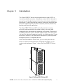


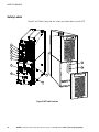

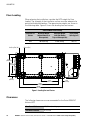
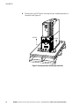
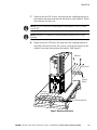
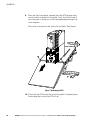
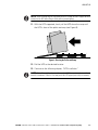

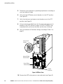
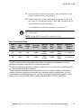
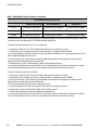
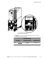
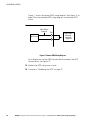
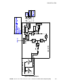

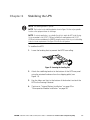
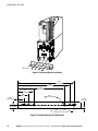
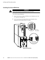
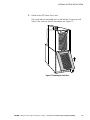
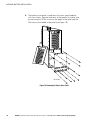
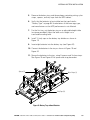
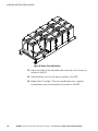
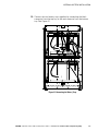
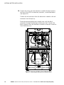


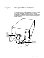

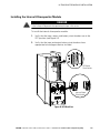
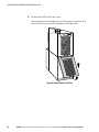
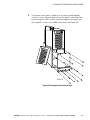
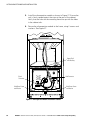

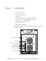
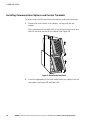
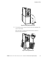
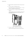

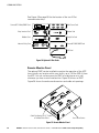
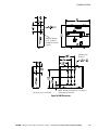
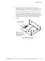
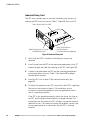
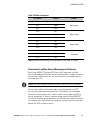
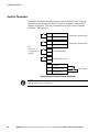
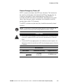


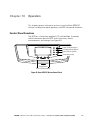
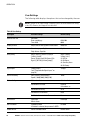
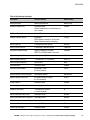

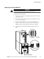
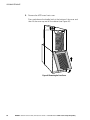
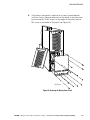
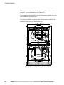
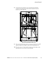
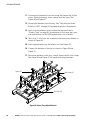
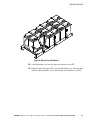
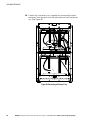
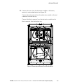
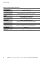
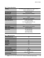
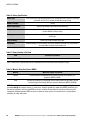

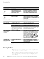
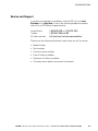


![E^YB?= ce``_bd VY\Uc V_b @QbQTYW] 4UReW BD](http://vs1.manualzilla.com/store/data/005839928_1-81490c34e940fa2480ecad1c81f1b8b0-150x150.png)