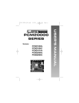
1
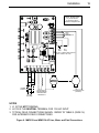
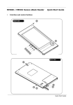
MODELS:
MM311U
MM301U
MM301A
User ’s Manual
MM300 Series
Isolated Input, Dual Voltage, Variable Speed SCR
Drives for Brush Motors
Copyright © 2013 by
Minarik Drives
All rights reserved. No part of this manual may be reproduced or transmitted in any form
without written permission from Minarik Drives. The information and technical data in this
manual are subject to change without notice. Minarik Drives and its Divisions make no
warranty of any kind with respect to this material, including, but not limited to, the implied
warranties of its merchantability and fitness for a given purpose. Minarik Drives and its
Divisions assume no responsibility for any errors that may appear in this manual and make
no commitment to update or to keep current the information in this manual.
Printed in the United States of America.
I
Safety Warnings
This symbol
denotes an important safety tip or warning. Please read these sec-
tions carefully prior to performing any of the instructions contained in that section.
• Have a qualified electrical maintenance technician install, adjust and service this
equipment. Follow the National Electrical Code and all other applicable electrical
and safety codes, including the provisions of the Occupational Safety
and Health Act (OSHA), when installing equipment.
• Reduce the chance of an electrical fire, shock, or explosion by proper grounding,
over-current protection, thermal protection, and enclosure. Follow sound maintenance procedures.
• It is possible for a drive to run at full speed as a result of a component failure.
Please ensure that a master switch has been placed in the AC line to stop the drive
in an emergency.
• This drive is isolated from earth ground. Circuit potentials are at 115 VAC or 230
VAC above earth ground. Avoid direct contact with the printed circuit board or with
circuit elements to prevent the risk of serious injury or fatality. Use a non-metallic
screwdriver for adjusting the calibration trimpots.
II
Contents
Safety Warnings . . . . . . . . . . . . . . . . . . . . . . . . . . . . . . . . . . . . . . . . . . . . . . . . . . . . . . .i
Specifications . . . . . . . . . . . . . . . . . . . . . . . . . . . . . . . . . . . . . . . . . . . . . . . . . . . . . . . . .1
Dimensions . . . . . . . . . . . . . . . . . . . . . . . . . . . . . . . . . . . . . . . . . . . . . . . . . . . . . . . . . .3
Installation . . . . . . . . . . . . . . . . . . . . . . . . . . . . . . . . . . . . . . . . . . . . . . . . . . . . . . . . . . .6
Wiring . . . . . . . . . . . . . . . . . . . . . . . . . . . . . . . . . . . . . . . . . . . . . . . . . . . . . . . . . . . . .6
Shielding Guidelines . . . . . . . . . . . . . . . . . . . . . . . . . . . . . . . . . . . . . . . . . . . . . . . . . .7
Chassis Drives (MM301U, MM311U) . . . . . . . . . . . . . . . . . . . . . . . . . . . . . . . . . . . .8
Mounting . . . . . . . . . . . . . . . . . . . . . . . . . . . . . . . . . . . . . . . . . . . . . . . . . . . . . . . . .8
Heatsinking . . . . . . . . . . . . . . . . . . . . . . . . . . . . . . . . . . . . . . . . . . . . . . . . . . . . . . .9
Line Fusing . . . . . . . . . . . . . . . . . . . . . . . . . . . . . . . . . . . . . . . . . . . . . . . . . . . . . . .9
Speed adjust potentiometer . . . . . . . . . . . . . . . . . . . . . . . . . . . . . . . . . . . . . . . . .10
Cage-clamp terminals . . . . . . . . . . . . . . . . . . . . . . . . . . . . . . . . . . . . . . . . . . . . . .11
Connections . . . . . . . . . . . . . . . . . . . . . . . . . . . . . . . . . . . . . . . . . . . . . . . . . . . . .12
Motor . . . . . . . . . . . . . . . . . . . . . . . . . . . . . . . . . . . . . . . . . . . . . . . . . . . . . . . . .12
Power Input . . . . . . . . . . . . . . . . . . . . . . . . . . . . . . . . . . . . . . . . . . . . . . . . . . .14
Field Output . . . . . . . . . . . . . . . . . . . . . . . . . . . . . . . . . . . . . . . . . . . . . . . . . . .14
START/STOP pushbuttons . . . . . . . . . . . . . . . . . . . . . . . . . . . . . . . . . . . . . . . .15
Tachometer feedback . . . . . . . . . . . . . . . . . . . . . . . . . . . . . . . . . . . . . . . . . . . .15
Voltage or current follower . . . . . . . . . . . . . . . . . . . . . . . . . . . . . . . . . . . . . . . .16
Slide switches . . . . . . . . . . . . . . . . . . . . . . . . . . . . . . . . . . . . . . . . . . . . . . . . .17
Enclosed Drives (MM301A) . . . . . . . . . . . . . . . . . . . . . . . . . . . . . . . . . . . . . . . . . .19
Mounting . . . . . . . . . . . . . . . . . . . . . . . . . . . . . . . . . . . . . . . . . . . . . . . . . . . . . . . .19
Heatsinking . . . . . . . . . . . . . . . . . . . . . . . . . . . . . . . . . . . . . . . . . . . . . . . . . . . . . .20
Line Fusing . . . . . . . . . . . . . . . . . . . . . . . . . . . . . . . . . . . . . . . . . . . . . . . . . . . . . .20
Connections . . . . . . . . . . . . . . . . . . . . . . . . . . . . . . . . . . . . . . . . . . . . . . . . . . . . .21
Motor . . . . . . . . . . . . . . . . . . . . . . . . . . . . . . . . . . . . . . . . . . . . . . . . . . . . . . . . .22
III
Operation . . . . . . . . . . . . . . . . . . . . . . . . . . . . . . . . . . . . . . . . . . . . . . . . . . . . . . . . . . .24
Before applying power (all models) . . . . . . . . . . . . . . . . . . . . . . . . . . . . . . . . . . . . .24
Chassis Drives (MM301U, MM311U) . . . . . . . . . . . . . . . . . . . . . . . . . . . . . . . . . . . .24
Speed adjust potentiometer input with START/STOP pushbuttons . . . . . . . . . . . .25
Diagnostic LEDs . . . . . . . . . . . . . . . . . . . . . . . . . . . . . . . . . . . . . . . . . . . . . . . . . . .26
Line starting and line stopping
. . . . . . . . . . . . . . . . . . . . . . . . . . . . . . . . . . . . . . . .27
Decelerating to minimum speed . . . . . . . . . . . . . . . . . . . . . . . . . . . . . . . . . . . . . . .27
Dynamic braking . . . . . . . . . . . . . . . . . . . . . . . . . . . . . . . . . . . . . . . . . . . . . . . . . . .28
Dynamic brake resistor value . . . . . . . . . . . . . . . . . . . . . . . . . . . . . . . . . . . . . . . . .28
Enclosed Drive Operating Modes (Manual / Auto) . . . . . . . . . . . . . . . . . . . . . . . . .30
Enclosed Drive Operation . . . . . . . . . . . . . . . . . . . . . . . . . . . . . . . . . . . . . . . . . . . .31
Calibration . . . . . . . . . . . . . . . . . . . . . . . . . . . . . . . . . . . . . . . . . . . . . . . . . . . . . . . . . .32
Drive Calibration Procedure . . . . . . . . . . . . . . . . . . . . . . . . . . . . . . . . . . . . . . . . . .34
MINIMUM SPEED (MIN SPD) . . . . . . . . . . . . . . . . . . . . . . . . . . . . . . . . . . . . . . . . .35
MAXIMUM SPEED (MAX SPD) . . . . . . . . . . . . . . . . . . . . . . . . . . . . . . . . . . . . . . . .35
CURRENT LIMIT . . . . . . . . . . . . . . . . . . . . . . . . . . . . . . . . . . . . . . . . . . . . . . . . . . .36
IR COMPENSATION (IR COMP) . . . . . . . . . . . . . . . . . . . . . . . . . . . . . . . . . . . . . .37
ACCELERATION (ACCEL) . . . . . . . . . . . . . . . . . . . . . . . . . . . . . . . . . . . . . . . . . . .39
DECELERATION (DECEL) . . . . . . . . . . . . . . . . . . . . . . . . . . . . . . . . . . . . . . . . . . .39
TACH VOLTS
. . . . . . . . . . . . . . . . . . . . . . . . . . . . . . . . . . . . . . . . . . . . . . . . . . . . .40
Application Notes . . . . . . . . . . . . . . . . . . . . . . . . . . . . . . . . . . . . . . . . . . . . . . . . . . . .42
Multiple fixed speeds . . . . . . . . . . . . . . . . . . . . . . . . . . . . . . . . . . . . . . . . . . . . . . . .42
Adjustable speeds using potentiometers in series . . . . . . . . . . . . . . . . . . . . . . . . .43
Independent adjustable speeds
Reversing
. . . . . . . . . . . . . . . . . . . . . . . . . . . . . . . . . . . . . . .44
. . . . . . . . . . . . . . . . . . . . . . . . . . . . . . . . . . . . . . . . . . . . . . . . . . . . . . . .45
RUN/JOG switch . . . . . . . . . . . . . . . . . . . . . . . . . . . . . . . . . . . . . . . . . . . . . . . . . . .46
Reversing with a DIGI=LOK Controller, Model DLC600 . . . . . . . . . . . . . . . . . . . . .47
IV
Troubleshooting . . . . . . . . . . . . . . . . . . . . . . . . . . . . . . . . . . . . . . . . . . . . . . . . . . . . . .48
Unconditional Warranty . . . . . . . . . . . . . . . . . . . . . . . . . . . . . . . . . . . . . . . . . . . . . . .54
V
Illustrations
Fig.
Description
1.
MM301U and MM311U Dimensions . . . . . . . . . . . . . . . . . . . . . . . . . . . . . . . . . .3
Page
2.
MM301A Dimensions . . . . . . . . . . . . . . . . . . . . . . . . . . . . . . . . . . . . . . . . . . . . . 4
3.
MM300 Series Layout . . . . . . . . . . . . . . . . . . . . . . . . . . . . . . . . . . . . . . . . . . . . .5
4.
Speed Adjust Potentiometer . . . . . . . . . . . . . . . . . . . . . . . . . . . . . . . . . . . . . . . .10
5.
Cage-Clamp Terminal . . . . . . . . . . . . . . . . . . . . . . . . . . . . . . . . . . . . . . . . . . . . .11
6.
MM301U and MM311U AC Line, Motor and Field Connections . . . . . . . . . . . . .13
7.
Signal Follower Connection . . . . . . . . . . . . . . . . . . . . . . . . . . . . . . . . . . . . . . . .16
8.
Slide Switches . . . . . . . . . . . . . . . . . . . . . . . . . . . . . . . . . . . . . . . . . . . . . . . . . .18
9.
MM301A Connections . . . . . . . . . . . . . . . . . . . . . . . . . . . . . . . . . . . . . . . . . . . .23
10.
Current Limit and Power LEDs . . . . . . . . . . . . . . . . . . . . . . . . . . . . . . . . . . . . . .26
11.
Run/Decelerate to Minimum Speed Switch . . . . . . . . . . . . . . . . . . . . . . . . . . . . .28
12.
Dynamic Brake Connection . . . . . . . . . . . . . . . . . . . . . . . . . . . . . . . . . . . . . . . .29
13.
Calibration Trimpot Layout . . . . . . . . . . . . . . . . . . . . . . . . . . . . . . . . . . . . . . . . .33
14.
Typical CURRENT LIMIT, and IR COMP Settings for MM300 Series
(actual settings may vary wtih each application) . . . . . . . . . . . . . . . . . . . . . . . .38
15.
Mutiple Fixed Speeds . . . . . . . . . . . . . . . . . . . . . . . . . . . . . . . . . . . . . . . . . . . . .42
16.
Adjustable Fixed Speeds Using Potentiometers in Series . . . . . . . . . . . . . . . . .43
17.
Independent Adjustable Speeds
18.
Reversing Circuit Connection . . . . . . . . . . . . . . . . . . . . . . . . . . . . . . . . . . . . . . .45
19.
RUN/JOG Switch Connection to Speed Adjust Potentiometer . . . . . . . . . . . . . .46
20.
Reversing with a DLC600 . . . . . . . . . . . . . . . . . . . . . . . . . . . . . . . . . . . . . . . . . .47
21.
MM300 Series Block Diagram . . . . . . . . . . . . . . . . . . . . . . . . . . . . . . . . . . . . . .52
. . . . . . . . . . . . . . . . . . . . . . . . . . . . . . . . . . . .44
VI
Tables
Fig.
Description
1.
Recommended Line Fuse Sizes . . . . . . . . . . . . . . . . . . . . . . . . . . . . . . . . . . . . .9
Page
2.
Field Output Connections for Chassis Drives . . . . . . . . . . . . . . . . . . . . . . . . . . .14
3.
Replacement Parts . . . . . . . . . . . . . . . . . . . . . . . . . . . . . . . . . . . . . . . . . . . . . . .53
1
Specifications
Model
Max.
Armature
Current
(Amps DC)
HP Range
with 115 VAC
Applied
HP Range
with 230 VAC
Applied
MM311U
3.0
1/20–1/8
1/10–1/4
MM301U
10.0
1/4–1
1/2–2
MM301A
10.0
1/4–1
1/2–2
AC Line Voltage
115 VAC or 230 V AC, 50 or 60 Hz, 1 Phase
Armature Voltage (115 VAC Input)
0–90 VDC
Armature Voltage (230 VAC Input)
0–180 VDC
Form Factor
1.37 at base speed
Field Voltage (115 VAC)
50 VDC (F1 to L1); 100 VDC (F1 to F2)
Field Voltage (230 VAC)
100 VDC (F1 to L1); 200 VDC (F1 to F2)
Maximum Field Current
1 ADC
Acceleration Time Range (with no load)
1-11 seconds
Deceleration Time Range (with no load)
1-11 seconds
Analog Input Voltage Range (S1 to S2)
Input Impedance (S1 to S2)
0-10 VDC or 4-20 mADC
>100K ohms
Load Regulation (% of base speed)
with Armature Feedback
with Tachogenerator Feedback
Vibration
1% or better
0.1%
0.5G max. (0-50 Hz); 0.1G max. (>50 Hz)
Specifications
2
Ambient Temperature Range
Open Chassis
10°C-55°C
Cased
10°C-45°C
Weight
Open Chassis
2.1 lbs (953 grams)
Cased
7.75 lbs (3.5 kilograms)
Tachogenerator Feedback Voltage Range
7-50 VDC per 1000RPM
Short-circuit current rating (SCCR) is the maximum short-circuit
current that the speed control can safely withstand when
protected by a specific over-current protective device(s).
The rating for models rated more than 1 HP is tabulated below:
Drive
Short Circuit
Model No. Current Rating
Types of Branch
Circuit Protection
Maximum
Rating of
Overcurrent
Protection
Maximum Maximum
Current,
Voltage,
kA
V
MM301U
10,000
240V
Non-time Inverse
Delay K5 Time
Circuit
Fuse
Breaker
30A
MM301A
10,000
240V
Non-time Inverse
Delay K5 Time
Fuse
Circuit
Breaker
30A
3
Dimensions
0.19 [5]
4.46 [113]
3.00 [76]
0.70 [18]
0.60 [15]
0.77 [19]
1.90 [48]
0.98 [25]
6.30 [160]
6.90 [175]
SIX (6) MOUNTING SLOTS
0.18 [5] WIDE x 0.30 [8] DEEP
ALL DIMENSIONS IN INCHES [MILLIMETERS]
Figure 1. MM301U and MM311U Dimensions
4
Dimensions
6.90 [175]
6.30 [160]
1.40
[36]
10.22
[260]
9.80
[249]
7.00
[178]
0.22
[6]
1.45 [37]
5.51
[140]
4.78
[121]
2.31
[59]
0.12
[3]
1.50 [38]
1.50 [38]
THREE 0.88 [22] KNOCKOUTS
ALL DIMENSIONS IN INCHES [MILLIMETERS]
Figure 2. MM301A Dimensions
Layout
5
ACCEL AND DECEL
TRIMMER POTENTIOMETERS
(P503, P504)
IR COMP
TRIMMER POTENTIOMETER
(P506)
FEEDBACK SELECTOR
SWITCH (SW505)
CURRENT LIMIT
TRIMMER POTENTIOMETER
(P505)
POWER LED
(IL502)
TACHOGENERATOR VOLTAGE
TRIMMER POTENTIOMETER
(P507)
CURRENT LIMIT
LED (IL501)
TACHOGENERATOR
TERMINAL BLOCKS
SPEED ADJUST POTENTIOMETER
TERMINAL BLOCKS
START/STOP
TERMINAL BLOCKS
LINE VOLTAGE
SELECTOR SWITCHES
(SW501, SW502)
10-TURN MAXIMUM
AND MINIMUM SPEED
TRIMMER POTENTIOMETERS
(P501, P502)
CURRENT/VOLTAGE
SIGNAL SELECTOR
SWITCH
(SW504)
AC LINE
FUSES
(FU501-FU502)
AC LINE VOLTAGE
TERMINAL BLOCKS
ARMATURE
TERMINAL BLOCKS
ARMATURE VOLTAGE
SELECTOR SWITCH
(SW503)
FIELD
TERMINAL BLOCKS
Figure 3. MM300 Series Layout
6
Installation
Wiring
Use 12 AWG wire for the AC line voltage (L1 and L2), motor armature (A1 and A2),
and dynamic brake resistor (if used). Use 18 AWG wire for logic (field output, speed
adjust potentiometer, tachogenerator, etc.)
Twist logic wires to avoid picking up unwanted electrical noise. Use shielded cable if
wires are longer than 12 inches (30 cm).
Do not bundle logic wires with power carrying wires. This can cause erratic operation.
Keep logic wires in a conduit separated by at least 2 inches from power carrying
wires. Do not allow logic wires to travel in parallel to power carrying wires for more
than 1 inch.
It may be necessary to earth ground the shielded cable. If noise is produced by
devices other than the drive, ground the shield at the drive end. If noise is generated
by a device on the drive, ground the shield at the end away from the drive. Do not
ground both ends of the shield.
Installation
7
Shielding guidelines
Warning
Under no circumstances should power and
logic leads be bundled together. Induced
voltage can cause unpredictable behavior in
any electronic device, including motor controls.
As a general rule, Minarik recommends shielding of all conductors. If it is not practical
to shield power conductors, Minarik recommends shielding all logic-level leads. If
shielding logic level leads is not practical, the user should twist all logic leads with
themselves to minimize induced noise.
It may be necessary to earth ground the shielded cable. If noise is produced by
devices other than the drive, ground the shield at the drive end. If noise is generated
by a device on the drive, ground the shield at the end away from the drive. Do not
ground both ends of the shield.
If the drive continues to pick up noise after grounding the shield, it may be necessary
to add AC line filtering devices, or to mount the drive in a less noisy environment.
Logic wires from other input devices, such as motion controllers and PLL velocity controllers, must be separated from power lines in the same manner as the logic I/O on
this drive.
8
Installation
Chassis Drives (MM301U, MM311U)
Mounting
Mount the drive with its board in either a horizontal or vertical plane. Four 0.188 inch (4.8
mm) wide slots in the chassis accept #8 pan head screws.
The chassis units do not have to be earth grounded. If you choose to ground the chassis, use a star washer beneath the head of at least one of the mounting screws to penetrate the anodized chassis surface and to reach bare metal.
Drive components are sensitive to electrostatic fields. Avoid contact with the circuit
board directly. Hold the drive by the chassis only.
Protect the drive from dirt, moisture, and accidental contact. Provide sufficient room for
access to the terminal block and calibration trimpots.
Mount the drive away from other heat sources. Operate the drive within the specified
ambient operating temperature range.
Prevent loose connections by avoiding excessive vibration of the drive.
Observe the following guidelines when installing an isolation transformer:
• A power disconnecting device must be installed between the power line and primary
of the transformer.
• If the power disconnecting device is a circuit breaker, the circuit breaker trip rating
must be coordinated with the in-rush current (10-12 times full load current) of the
transformer.
Installation
9
Heatsinking
The MM301U and MM311U contain sufficient heat sinking in its original configuration.
No additional heat sinking is necessary when installed in accordance with the guidelines specified in this instruction manual. The chassis plate acts as the thermal
heatsink.
Line fusing
MM300 Series drives have line fuses mounted on fuse holders 501 and 502 (FU501
and FU502). See the Replacement Parts section for preinstalled line fuse size. When
replacing the line fuses, use fast acting fuses rated for 250 VAC or higher, and at
least 200% of the armature current. See Figure 3 (page 5) for fuse holder location,
and Table 1 for recommended line fuse sizes.
Table 1. Recommended Line Fuse Sizes
90 VDC Motor
Horsepower
180 VDC Motor
Horsepower
Max. DC Armature
Current (amps)
AC Line Fuse
Size (amps)
1/20
1/10
0.5
1/15
1/8
0.8
3
3
1/8
1/4
1.5
5
1/6
1/3
1.7
5
1/4
1/2
2.6
8
1/3
3/4
3.5
8
1/2
1
5.0
10
7.6
15
3/4
1 1/2
Minarik Drives offers a 63 mA pico fuse (part number 050-0081) which protects the transformer
and logic.
10
Installation
Speed adjust potentiometer
Install the circular insulating disk between the mounting panel and the 10K ohm speed
adjust potentiometer (see Figure 4). Mount the speed adjust potentiometer through a
0.38 inch (10 mm) hole with the hardware provided. Twist the speed adjust potentiometer wire to avoid picking up unwanted electrical noise. If potentiometer leads are
longer than 18 inches (46 cm), use shielded cable.
Alternate speed adjust potentiometer connections may be found in the Application
Notes section of this user guide.
Note: The user may choose to install a 5K ohm speed adjust potentiometer; however, the MIN SPD and MAX SPD trimpots must be recalibrated if the 5K ohm potentiometer is used.
Figure 4. Speed Adjust Potentiometer
Installation
11
Cage-clamp terminals
Logic connections are made to a cage-clamp terminals. To insert a wire into the cageclamp terminal:
1. Press down on the lever arm using a
small screwdriver.
2. Insert wire into the wire clamp
3. Release the lever arm to clamp wire.
Figure 5. Cage-Clamp Terminal
12
Installation
Connections
Motor
Warning
Under no circumstances should power and
logic leads be bundled together. Induced
voltage can cause unpredictable behavior in
any electronic device, including motor controls.
Connect a motor to terminals A1 and A2 as shown in Figure 6 (page 13). Ensure that
the motor voltage rating is consistent with the drive’s output voltage.
Minarik drives supply motor voltage from A1 and A2 terminals (TB501). It is assumed
throughout this manual that when A1 is positive with respect to A2, the motor will
rotate clockwise (CW) while looking at the output shaft protruding from the front of the
motor. If this is opposite of the desired rotation, simply reverse the wiring of A1 and
A2 with each other.
Installation
NOTE: DO NOT make
any connections to
F1 and F2 if using a
permanent magnet motor.
SPEED
ADJUST
POTENTIOMETER
10K OHMS
N.O.
Start
N.C.
Stop
NOTE: IF PUSHBUTTONS ARE NOT
USED, CONNECT B1 TO B3.
115
VAC
230
VAC
POWER
SWITCH
AC LINE
VOLTAGE
FIELD OUTPUT
SHUNT-WOUND
MOTORS ONLY
SEE NOTE 4
TACHOGENERATOR
(OPTIONAL)
NOTES
1. L1 IS THE HOT TERMINAL.
2. L2/115 IS THE NEUTRAL TERMINAL FOR 115 VAC INPUT.
3. TYPICAL FIELD CONNECTIONS SHOWN. REFER TO TABLE 2 (PAGE 14)
FOR ALTERNATE FIELD CONNECTIONS.
Figure 6. MM301U and MM311U AC Line, Motor and Field Connections
13
Installation
14
Power Input
Connect the AC line power leads to terminals L1 and L2 and install a master power
switch in the voltage input line as shown in Figure 6 (page 13). The switch contacts
should be rated at a minimum of 250 volts and 200% of maximum drive current.
Field output
The field output is for shunt wound motors only. Do not make any connections to
F1 and F2 (TB501) when using a permanent magnet motor. See Table 2 for field
output connections.
Table 2. Field Output Connections for Chassis Drives
Line Voltage
Approximate
Connect Motor
(VAC)
Field Voltage (VDC)
Field To
115
50
F1 and L1
115
100
F1 and F2
230
100
F1 and L1
230
200
F1 and F2
Installation
15
START/STOP pushbuttons
Pushbutton operation of the MM300 Series requires a momentary normally open STOP
pushbutton be wired to terminals B2 and B3 and a momentary normally closed START
pushbutton wired to terminals B1 and B2. These switches must be used together and
are not included with the drive. The B1, B2 and B3 terminals are on terminal block
TB502.
If the START/STOP pushbuttons are not used, wire a jumper between terminals B1
and B3 to bypass the latching circuit. The drive will then operate in a power-up start
mode. See Figure 6 (page 13) for these switch connections.
Tachometer feedback
Using tachometer feedback improves speed regulation from approximately 1% of
motor base speed to approximately 0.1% of motor base speed. Use tachometers
rated from 7 VDC per 1000 RPM to 50 VDC per 1000 RPM. Connect the tachometer
to terminals T1 and T2 of terminal block 502 (TB502). Place SW504 in the TACH
position. See Figure 6 (page 13) for tachometer connections. The TACH trimpot trimpot must be adjusted prior to operating with tachometer feedback. Refer to the
Calibration section for instructions on calibrating the TACH trimpot.
16
Installation
Voltage or current follower
Instead of using a speed adjust potentiometer, MM300 Series drives may be wired to
follow an analog input signal (see Figure 6 for connections). This input signal can be
in the form of voltage (0-10 VDC) or current (4-20 mA). Because these drives have
built in isolation the input signal can be either grounded or ungrounded. The signal
slide switch must also be set for current or voltage input (see Slide switches section).
Figure 7. Signal Follower Connection
Installation
17
Slide switches
Warning
Change slide switch settings only when the
drive is disconnected from the AC line voltage. Make sure both line voltage and motor
switches are set to their correct position. If
the switches are improperly set to a lower
voltage position, the motor will not run at
full voltage and may cause transformer
damage. If the switches are improperly set
to a higher voltage position, the motor will
over speed, which may cause motor damage.
LINE VOLTAGE (SW501 and SW502)
Select the appropriate line voltage: 115 for 115 VAC line voltage, or 230 for 230 VAC
line voltage.
MOTOR (SW503)
Select the maximum armature voltage: 90V for 90 VDC motors, or 180V for 180 VDC
motors.
SIGNAL (SW504)
Select the input signal being used: CURR for current input signal, or VOLT for voltage
input signal or speed adjust potentiometer input.
18
Installation
FEEDBACK (SW505)
Select the appropriate feedback option: ARMATURE for armature feedback, or TACH
for tachometer feedback.
See Figure 8 for all slide switch locations.
VOLTAGE
SELECT
SWITCHES
(SW501,SW502)
FEEDBACK SELECT
SWITCH (SW505)
18
ARMATURE
A
VOLTAGE
SELECT
(SW503)
G
SIGNAL
SOURCE
SELECT
(SW504)
Figure 8. Slide Switches
Installation
19
Enclosed drive
Mounting
The NEMA 4X enclosed drive comes with 0.88 inch (22mm) conduit knockout holes at
the bottom of the enclosure. The units may be vertically wall mounted using the four
0.19 inch (5 mm) slotted holes on the attached heat sink. For motor loads less than
5 ADC, the drive may be bench mounted horizontally, or operated without mounting.
Mount the drive as follows:
1. Install the mounting screws.
2. For access to the terminal strip, turn the slotted screw on the front cover
counterclockwise until it is free from the enclosure. The right side of the
cover is hinged to the enclosure. Pull the slotted screw to open the enclosure.
3. Carefully remove the conduit knockouts by tapping them into the enclosure
and twisting them off with pliers.
4. Install conduit hardware through the 0.88 inch (22 mm) knockout holes.
Connect external wiring to the terminal block.
5. Grasp the slotted screw and tilt the front cover back into place. Avoid
pinching any wires between the front cover and the enclosure.
6. Turn the slotted screw clockwise until tight to secure the front cover.
7. Set the POWER switch to the OFF position before applying AC
line voltage.
20
Installation
Heat sinking
The enclosed MM300 Series drive contains sufficient heat sinking in its basic configuration.
No additional heat sinking is necessary when installed in accordance with the guidelines
specified in this manual.
Line fusing
WARNING: Most code requires that upstream
branch protection be provided to protect input
power wiring. Failure to observe this precaution
could result in severe bodily injury or loss of life.
This MM300U Series has 15-amp line fuses preinstalled on fuse holders 501 and 502
(FU501 and FU502). When replacing the line fuses, use fast acting fuses rated for
250 VAC or higher. See Figure 3 (page 5) for fuse holder location and Table 1
(page 9) for recommended line fuse sizes.
Installation
Connections
WARNING: A single fault like a power device
short may cause motor rotation when in the
stop mode. The user is responsible for assuring safe conditions for operating personal by
providing suitable guards, audio or visual alarms, or other devices. Failure to observe
these precautions could result in bodily injury.
WARNING: To provide the motor with overload protection, local, national, and international codes (e.g.,NEC/CEC) require that
a motor thermostat, internal to the motor, be
installed or an electronic thermal motor overload relay, sized to protect the motor, installed between the motor and the drives’ output terminals.
WARNING: Do not connect this equipment
with power applied. Failure to observe this
precaution may result in fire or serious injury.
21
22
Installation
Connections
Motor
Warning
Under no circumstances should power and
logic leads be bundled together. Induced
voltage can cause unpredictable behavior in
any electronic device, including motor controls.
Connect a motor to terminals A1 and A2 as shown in Figure 9 (page 23). Ensure that
the motor voltage rating is consistent with the drive’s output voltage.
Minarik Drives motor speed controls supply motor voltage from A1 and A2 terminals.
It is assumed throughout this manual that when A1 is positive with respect to A2, the
motor will rotate clockwise (CW) while looking at the output shaft protruding from the
front of the motor. If this is opposite of the desired rotation, simply reverse the wiring
of A1 and A2 with each other.
8
9
RE F
7
23
COM
6
A2
5
A1
4
F1
3
L2 (115)
2
L2 (230)
L1
1
F2
Installation
COM (–)
REF (+)
–
230 VAC
MOTOR
ARMATURE
SEE NOTES 1,
2, AND 3
+
115 VAC
EARTH GROUND
(GREEN SCREW)
115/230 VAC
LINE VOLTAGE INPUT
FIELD
COIL
SEE NOTE 4
1.
2.
3.
4.
5.
0 – 10 VDC OR
4 – 20 mADC
INPUT SIGNAL
L1 IS THE HOT TERMINAL.
L2/115 IS THE NEUTRAL TERMINAL FOR 115 VAC INPUT.
L2/230 IS THE NEUTRAL TERMINAL FOR 230 VAC INPUT.
TYPICAL FIELD CONNECTIONS SHOWN. REFER TO TABLE 2 (PAGE 14)
REMOVE THE 510 OHM INTERNAL RESISTOR CONNECTED BETWEEN
TERMINALS 8 & 9 IF YOU ARE USING A 0-10V REMOTE INPUT SIGNAL
Figure 9. MM301A AC Line, Motor and Field Connections
24
Operation
Before applying power
1. Set LINE VOLTAGE SELECT switches SW501 and SW502 to either 115V or 230V
to match the AC line voltage.
2. Set ARMATURE VOLTAGE SELECT switch SW503 to either 90V or 180V to
match the maximum armature voltage.
3. Set SIGNAL SELECT switch SW504 to CURR if using a 4-20 mADC current signal; set it to VOLT if using a 0-10VDC voltage signal or the speed adjust potentiometer.
4. Verify that no conductive material is present on the printed circuit board.
5. If using a 90 VDC or 130 VDC motor with 230 VAC line voltage, derate the nameplate motor torque by at least 30%. The form factor will increase beyond the typical value, causing increased motor heating. Contact the factory for details.
Chassis Drives (MM301U, MM311U)
Speed adjust potentiometer input, no START/STOP pushbutton:
It is necessary to wire a jumper between B1 and B3 if no START/STOP switches are
to be used.
1. Turn the speed adjust potentiometer full counterclockwise (CCW).
Operation
25
2. Apply AC line voltage.
3. Slowly advance the speed adjust potentiometer clockwise (CW). The motor slowly
accelerates as the potentiometer is turned CW. Continue until the desired speed is
reached.
4. Remove AC line voltage to coast the motor to a stop.
Speed adjust potentiometer input with START/STOP pushbuttons:
1. Turn the speed adjust potentiometer full counterclockwise
(CCW).
2. Apply AC line voltage.
3. Press the START pushbutton.
4. Slowly advance the speed adjust potentiometer clockwise (CW). The motor accelerates as the potentiometer is turned clockwise. Continue until desired speed is
reached.
5. Press STOP pushbutton to coast motor to a stop.
Analog signal input, no START/STOP pushbuttons:
It is necessary to wire a jumper between B1 and B3 if no START/STOP switches are
to be used.
1. Set the analog signal so that it is at its lowest level
(0V or 4mA).
2. Apply AC line voltage.
3. Slowly increase the analog signal. The motor accelerates as the signal is increased.
Continue increasing signal until desired speed is reached.
4. Remove AC line voltage to coast the motor to a stop.
26
Operation
Analog signal input with START/STOP pushbuttons:
1. Set the analog signal so that it is at its lowest level
(0V or 4mA).
2. Apply AC line voltage.
3. Press the START pushbutton.
4. Slowly increase the analog signal and press the start pushbutton. The motor accelerates as the signal is increased. Continue increasing signal until desired speed is
reached.
5. Press STOP pushbutton to coast motor to a stop.
Diagnostic LEDs
MM300 Series drives are equipped with two diagnostic LEDs (see Figure 10 for LED
location). The red current limit LED turns on whenever the drives reaches current limit
and stays off whenever the drive is not in current limit (normal operation). The green
power LED turns on whenever AC line voltage is applied to the drive and stays off
whenever there is no AC line voltage applied to the drive.
Figure 10. Current Limit and Power LEDs
Operation
27
Line starting and line stopping
Line starting and line stopping (applying and removing AC line voltage) is recommended for infrequent starting and stopping of a drive only. When AC line voltage is
applied to the drive and a START is commanded, the motor accelerates to the speed
set by the speed adjust potentiometer or analog input signal. When AC line voltage is
removed, the motor coasts to a stop.
Decelerating to minimum speed
The circuit shown in Figure 11 (page 28) may be used to decelerate a motor to a minimum speed. Closing the switch between S1 and S2 decelerates the motor from set
speed to a minimum speed determined by the MIN SPD trimpot setting. If the MIN SPD
trimpot is set full CCW, the motor decelerates to zero speed when the switch between
S1 and S2 is closed. The DECEL trimpot setting determines the rate at which the drive
decelerates. By opening the switch the motor accelerates to set speed at a rate determined by the ACCEL trimpot setting.
28
Operation
Figure 11. Run/Decelerate to Minimum Speed Switch
Dynamic Braking
Dynamic braking may be used to rapidly stop a motor (Figure 12, page 29). For the
RUN/BRAKE switch, use a three pole, double throw switch rated for at least the maximum DC armature voltage, 15 amps. For the dynamic brake resistor, use a 40 Watt
minimum, high power, wirewound resistor.
Dynamic Brake Resistor Value
Sizing the dynamic brake resistor depends on load inertia, motor voltage and braking
time. Use a lower-value, higher wattage dynamic brake resistor to stop a motor more
rapidly. A good starting point is a 40 Ohm, 40 Watt.
Operation
Warning
Wait for the motor to completely stop before
switching it back to RUN. This will prevent
high armature currents from damaging the
motor.
MM300 Series Drive
A1
A2
DYNAMIC
BRAKE
RESISTOR
RUN
BRAKE
MOTOR
Figure 12. Dynamic Brake Connection
B1
B3
29
30
Operation
Enclosed drive operating modes
WARNING: If you run the drive in AUTO mode, you
must recalibrate the MIN SPD trimpot to offset any
motor drift caused by the input signal. Refer to the
Calibration section (page 32) for more information.
The mode selector switch on the drive, mounted on its cover, provides the option of
operating in either MANUAL (mounted speed potentiometer) or AUTO (external
signal source) mode.
Manual mode
Set the mode selector switch to MANUAL if you wish to control the motor speed using
the speed adjust potentiometer mounted on the drive cover. In MANUAL mode, the
motor speed is controlled by the speed adjust knob located on the drive cover. Setting
the speed adjust knob to zero causes the motor to run at the minimum speed
dictated by the MIN SPD trimpot setting. Refer to the Calibration section (page 32) for
information on calibrating the MIN SPD trimpot. Set SIGNAL SELECT switch SW504
to VOLT when in manual mode.
Auto mode
IMPORTANT: When switching between MANUAL and AUTO modes, you must balance the
MIN SPD trimpot for both operating modes.
Set the mode selector switch to AUTO if you wish to follow an external signal, independent
of the speed adjust knob setting. In AUTO mode, the drive will control motor speed in
proportion to either a 0 – 10 VDC analog voltage or a 4 – 20 mADC current signal. You
must set select switch SW504 to either VOLT to follow a 0 -10 VDC analog voltage or
to CURR to follow a 4 - 20 mADC current signal.
Operation
31
Enclosed drive operation
WARNING: For frequent starts and stops, open
the B1 and B3, decelerate to a minimum speed, or
apply a dynamic brake to the motor. Do not use any of
these methods for emergency stopping. They may not
stop a drive that is malfunctioning. Removing AC line
power (both L1 and L2) is the only acceptable method
for emergency stopping.
WARNING: Frequent starting and stopping can
produce high torque. This may cause damage to
motors, especially gearmotors that are not properly
sized for the application.
To run the motor:
1.
Set the speed adjust potentiometer to “0” (full CCW).
2.
Apply AC line voltage.
3.
Set the POWER switch to the ON position.
4.
Slowly advance the speed adjust potentiometer clockwise (CW), or increase the
external reference signal. The motor will slowly accelerate to follow the speed
adjust potentiometer or external reference signal. Continue until the desired
speed is reached.
To stop the motor:
1.
Rotate the speed adjust potentiomter to zero (full
CCW), or set the external reference signal to zero.
The motor will slowly decelerate until minimum speed
is reached.
2.
Set the POWER switch on the front panel to OFF.
32
Calibration
WARNING: Dangerous voltages exist on the
drive when it is powered, and up to 30 seconds
after power is removed and the motor stops. When
possible, disconnect the voltage input from the
drive before adjusting the trimpots. If the trimpots
must be adjusted with power applied, use insulated
tools and the appropriate personal protection
equipment. BE ALERT. High voltages can cause
serious or fatal injury.
WARNING: The control circuit is at line potential
when the drive is energized. Exercise extreme
caution as hazardous voltage exists.
MM300 Series drives have seven user adjustable trimpots. Each drive is factory calibrated to its maximum current rating. Readjust the calibration trimpot settings to
accommodate lower current rated motors.
All adjustments increase with CW rotation, and decrease with CCW rotation. Use a
non-metallic screwdriver for calibration. Each trimpot is identified on the printed circuit
board. Refer to Figure 13 for trimpot layouts.
Calibration
IR COMP
33
CURRENT
LIMIT
TACH
VOLTS
DECELERATION
ACCELERATION
MINIMUM SPEED
MAXIMUM SPEED
13. Calibration Trimpot Layout
34
Calibration
Drive Calibration Procedure
Prepare the MM300 series drive for calibration as follows. This procedure applies to
both chassis and enclosed drives.
1. Ensure that no power is applied to the drive.
2. If you use an enclosed drive, you must open the drive cover to gain access to the
trimpots. Turn the slotted screw on the front cover counterclockwise until it is free
from the enclosure. The right side of the cover is hinged to the enclosure. Pull the
slotted screw to open the enclosure.
3. Set all trimpots except CURRENT LIMIT and TACH VOLTS full counterclockwise
(CCW).
4. Set the CURRENT LIMIT trimpot full clockwise (CW).
5. Make no adjustment to the TACH VOLTS trimpot unless tachometer feedback is
used. If you use tachometer feedback, set the TACH VOLTS trimpot to the center
of travel (12 o’clock position).
6. Adjust the trimpots in the following order:
a. MINIMUM SPEED (MIN SPD)
b. MAXIMUM SPEED (MAX SPD)
c. CURRENT LIMIT
d. IR COMPENSATION (IR COMP)
e. ACCELERATION (ACCEL)
f. DECELERATION (DECEL)
g. TACH VOLTS (if used)
Calibration
35
MINIMUM SPEED (MIN SPD)
The MIN SPD setting determines the motor speed when the speed adjust potentiometer or input signal is set for minimum speed. It is factory set to zero speed.
To calibrate MIN SPD:
1. Turn the speed adjust potentiometer full CCW or set the input signal for minimum
voltage or current.
2. Adjust the MIN SPD trimpot until the motor has stopped, or is running at the
desired minimum speed.
MAXIMUM SPEED (MAX SPD)
The MAX SPD setting determines the motor speed when the speed adjust potentiometer or input signal is set for maximum speed. It is factory set for maximum rated motor
speed.
To calibrate MAX SPD:
1. Set the MAX SPD trimpot full CCW.
2. Turn the speed adjust potentiometer full CW or set the input signal for maximum
speed.
3. Adjust the MAX SPD trimpot until the desired maximum motor speed is reached.
Note: Check the MIN SPD and MAX SPD settings after recalibrating to verify that the
motor runs at the desired minimum and maximum speeds.
36
Calibration
CURRENT LIMIT
The CURRENT LIMIT setting determines the maximum armature current output of the
drive. It is factory set at 120% of rated motor current.
To calibrate CURRENT LIMIT, refer to Figure 13 (page 33), or use the following procedure:
1. With the power disconnected from the drive, connect a DC ammeter in series with
the armature.
2. Set the CURRENT LIMIT trimpot to minimum (full CCW).
3. Lock the motor armature. Be sure that the motor is firmly mounted.
4. Connect power to the drive. The motor should remain stopped.
5. Set the speed adjust potentiometer or input signal for maximum speed.
6. Adjust the CURRENT LIMIT trimpot slowly CW until the armature current is 120%
of motor rated current.
7. Set the speed adjust potentiometer or input signal for zero speed.
8. Remove power from the drive.
9. Remove the stall from the motor.
Calibration
37
IR COMPENSATION (IR COMP)
The IR COMP setting determines the degree to which motor speed is held constant
as the motor load changes. It is factory set at optimum motor regulation for the highest motor horsepower.
To calibrate IR COMP, refer to Figure 13 (page 33), or use the following procedure:
1. Turn the IR COMP trimpot full CCW.
2. Set the speed adjust potentiometer or input signal until the motor runs at midspeed
without load (for example, 900 RPM for an 1800 RPM motor). A hand held
tachometer may be used to measure motor speed.
3. Load the motor armature to its full load armature current rating. The motor should
slow down.
4. While keeping the load on the motor, rotate the IR COMP trimpot until the motor
runs at the speed measured in step 2.
Approximate calibration:
If the motor does not maintain set speed as the load changes,
gradually rotate the IR COMP trimpot CW. If the motor oscillates (overcompensation),
the IR COMP trimpot may be set too high (CW). Turn the IR COMP trimpot CCW to
stabilize the motor speed.
38
Calibration
MM311U
CURRENT
LIMIT
CURRENT
LIMIT
IR
COMP
IR
COMP
1/8 HP
90 VDC
1750 RPM
1.3 ADC
CURRENT
LIMIT
1/4 HP
180 VDC
1750 RPM
1.4 ADC
CURRENT
LIMIT
IR
COMP
IR
COMP
1/8 HP
180 VDC
1750 RPM
0.8 ADC
1/10 HP
90 VDC
1750 RPM
5 ADC
CURRENT
LIMIT
IR
COMP
1/15 HP
90 VDC
1750 RPM
0.75 ADC
MM301U and MM301A
CURRENT
LIMIT
CURRENT
LIMIT
IR
COMP
IR
COMP
1 HP
90 VDC
1750 RPM
10 ADC
CURRENT
LIMIT
1 HP
180 VDC
1750 RPM
5 ADC
CURRENT
LIMIT
IR
COMP
IR
COMP
1/2 HP
90 VDC
1750 RPM
5 ADC
CURRENT
LIMIT
1/2 HP
180 VDC
1750 RPM
2.5 ADC
CURRENT
LIMIT
IR
COMP
1/4 HP
90 VDC
1750 RPM
1.4 ADC
IR
COMP
1/4 HP
90 VDC
1750 RPM
1.2 ADC
Figure 14. Typical CURRENT LIMIT, and IR COMP Settings for MM300 Series
(actual settings may vary with each application)
Calibration
39
ACCELERATION (ACCEL)
The ACCEL setting determines the time the motor takes to ramp to a higher speed,
within the limits of available torque. The ACCEL setting is factory set for its fastest
acceleration time (full CCW).
To calibrate ACCEL:
1. Set the speed adjust potentiometer or input signal for minimum speed. The motor
should run at minimum speed.
2. Set the speed adjust potentiometer or input signal to maximum speed, and measure the time it takes the motor to go from minimum to maximum speed.
3. If the time measured in step 2 is not the desired acceleration time, turn the ACCEL
trimpot CW for a slower acceleration time, or CCW for a faster acceleration time.
Repeat steps 1 through 3 until the acceleration time is correct.
DECELERATION (DECEL)
The DECEL setting determines the time the motor takes to ramp to lower speed, within the limits of available torque. The DECEL setting is factory set for its fastest deceleration time (full CCW).
40
Calibration
To calibrate DECEL:
1. Set the speed adjust potentiometer or input signal for maximum speed. The motor
should run at maximum speed.
2. Set the speed adjust potentiometer or input signal for minimum speed and measure
the time it takes the motor to go from maximum to minimum speed.
3. If the time measured in step 2 is not the desired deceleration time, turn the DECEL
trimpot CW for a slower deceleration time, or CCW for a faster deceleration time.
Repeat steps 1 through 3 until the deceleration time is correct.
TACH VOLTS
Calibrate the TACH VOLTS setting only when a tachometer is used. The TACH
VOLTS setting, like the IR COMP setting, determines the degree to which the motor
speed is held constant as the motor load changes.
To calibrate the TACH VOLTS trimpot:
1. Connect the tachometer to T1 and T2. The polarity is (+) for T1 and (–) for T2 when
the motor is running in forward direction.
2. Set switch SW505 to ARM for armature feedback.
3. Set the speed adjust potentiometer or input signal to maximum speed.
4. Measure the armature voltage across A1 and A2 using a voltmeter.
Calibration
41
5. Set the speed adjust potentiometer or input signal to minimum speed.
6. Remove power from the drive.
7. Set SW505 to TACH for tachometer feedback.
8. Connect power to the drive.
9. Set the IR COMP trimpot full CCW.
10. Set the TACH VOLTS trimpot full CW.
11. Set the speed adjust potentiometer or input signal to
maximum speed.
12. Adjust the TACH VOLTS trimpot until the armature voltage is the same value as
the voltage measured in step 3.
Check that the TACH VOLTS trimpot is properly calibrated. The motor should run at
the same set speed when SW503 is set to either armature or tachometer feedback.
42
Application Notes
Multiple fixed speeds
Replace the speed adjust potentiometer with series resistors with a total series resistance of 10K ohms (Figure 15). Add a single pole, multi-position switch with the correct
number of positions for the desired number of fixed speeds.
Figure 15. Multiple Fixed Speeds
Application Notes
43
Adjustable speeds using potentiometers in series
Replace the speed adjust potentiometer with a single pole, multi-position switch, and
two or more potentiometers in series, with a total series resistance of 10K ohms.
Figure 16 shows a connection for fixed high and low speed adjust potentiometers.
Figure 16. Adjustable Fixed Speeds Using Potentiometers in Series
Application Notes
44
Independent adjustable speeds
Replace the speed adjust potentiometer with a single pole, multi-position switch, and
two or more potentiometers in parallel, with a total parallel resistance of 10K ohms.
Figure 17 shows the connection of two independent speed adjust potentiometers that
can be mounted at two separate operating stations.
S3
SPEED 2
S2
SPEED 1
CW
20K
OHM
S1
Figure 17. Independent Adjustable Speeds
CW
20K
OHM
Application Notes
45
Reversing
A dynamic brake may be used when reversing the motor direction (Figure 18). Use a
two pole, three position switch rated for at least the maximum DC armature voltage
and maximum braking current. Wait for the motor to stop completely before switching
it to either the forward or reverse direction. See the Dynamic braking section, page
28, for sizing the dynamic brake resistor.
Figure 18. Reversing Circuit Connection
46
Application Notes
RUN/JOG switch
Using a RUN/JOG switch is recommended in applications where quick stopping is not
needed and frequent jogging is required. Use a single pole, two position switch for the
RUN/JOG switch, and a single pole, normally closed, momentary operated pushbutton for the JOG pushbutton.
Connect the RUN/JOG switch and the JOG pushbutton as shown in Figure 19. When
the RUN/JOG switch is set to JOG, the motor decelerates to minimum speed (minimum speed is determined by the MIN SPD trimpot setting). Press the JOG pushbutton to jog the motor. Return the RUN/JOG switch to RUN for normal operation.
Figure 19. RUN/JOG Switch Connection to Speed Adjust Potentiometer
Application Notes
47
Reversing with a DIGI-LOK Controller (DLC600)
A DIGI-LOK controller, model DLC600 can be used in a reversing application. The
DIGI-LOK must be inhibited while braking. Without the inhibit feature, the DIGI-LOK
will continue to regulate. This will cause overshoot when the DIGI-LOK is switched
back to the drive. Figure 20 shows the connection of the reversing circuit to a
MM300 series drive and to a DLC600. Note: Only one DLC option (Optical Encoder
or Magnetic Pickup) may be used at a time.
S3
MINARIK
DRIVE
A1
S2
S1
A2
Dynamic
Brake
Resistor
S1
S2
BRAKE
REV
DLC600
FWD
Inhibit
Leads
C
Motor
Common
Optical
Encoder
Signal
+5 VDC
Magnetic
Pickup
Figure 20. Reversing with a DLC600
IN
+
48
Troubleshooting
Warning
Dangerous voltages exist on the drive when it is
powered. When possible, disconnect the drive
while troubleshooting. High voltages can cause
serious or fatal injury.
Check the following steps before proceeding:
1. The AC line voltage must be balanced, and match the voltage on the drive nameplate.
2. On dual voltage drives, check that the slide switches are set to the correct position.
3. The motor must be rated for the drive’s rated armature (all motors) and field outputs (shunt wound motors only).
4. Do not make any connections to F1 and F2 when a permanent magnet motor is
used.
5. Terminal block connections should be consistent with the connections shown in
this manual.
6. Check that line fuses FU501 and F502 are properly sized and not blown.
For additional assistance, contact your local Minarik distributor, or the factory direct:
PHONE: (800) MINARIK or (800) 646-2745
FAX: (800) 624-6960
Troubleshooting
Problem
Possible
Causes
Suggested
Solutions
Line fuse blows
1. Line fuses are the wrong
size.
1. Check that line fuses are
correct for motor size (page
9).
2. Motor cable or armature
is shorted to ground.
2. Check motor cable and
armature for shorts.
3. Nuisance tripping caused
by a combination of ambient conditions and highcurrent spikes (i.e.
reversing).
3. Add a blower to cool the
drive components, or
decrease the duty cycle of
the system.
4. Field circuit is open.
4. Send drive to Minarik repair
department.
1. MIN SPD and MAX SPD
settings are too high.
1. Recalibrate MIN SPD and
MAX SPD.
2. Motor field connections
are loose (shunt wound
motors only).
2. Check motor field connections.
3. Motor is demagnetized.
3. Check for proper braking
technique and method by
which power is cycled.
4. Tachometer leads are
reversed.
4. Check tachometer connections.
Motor runs too fast at
maximum speed setting
49
50
Troubleshooting
Problem
Possible
Causes
Suggested
Solutions
Line fuse does not
blow, but the motor
does not run
1. Speed adjust pot, voltage
input signal, or current input
signal set to zero speed.
1. Increase the speed adjust
pot, voltage, or current setting.
2. Speed adjust pot, voltage
input signal, or current input
signal not connected to
drive input properly; connections are open.
2. Check connections
to input. Verify that connections are not open.
3. S2 is shorted to S1.
3. Remove short.
4. Drive is in current limit.
4. Verify that motor is not
jammed. Increase CURRENT LIMIT setting if it is
set too low.
5. Drive is not receiving AC
line voltage.
5. Apply AC line voltage to L1
and L2.
6. Motor is not connected.
6. Connect motor to A1 and
A2.
7. B1 not connected
to B3 (if START/STOP pushbuttons are not used).
7. Connect B1 to B3.
Troublshooting
51
Problem
Possible
Causes
Suggested
Solutions
Line fuse blows
1. Line fuses are the wrong size.
1. Check that line fuses are
correct for motor size (page
9).
2. Motor cable or armature is
shorted to ground.
2. Check motor cable and
armature for shorts.
3. Nuisance tripping caused by a
combination of ambient conditions and high-current spikes
(i.e. reversing).
3. Add a blower to cool the
drive components, or
decrease the duty cycle of
the system.
4. Field circuit is open.
4. Send drive to Minarik repair
department.
1. MIN SPD and MAX SPD settings are too high.
1. Recalibrate MIN SPD and
MAX SPD.
2. Motor field connections are
loose (shunt wound motors
only).
2. Check motor field connections.
3. Motor is demagnetized.
3. Check for proper braking
technique and method by
which power is cycled.
4. Tachometer leads are
reversed.
4. Check tachometer connections.
Motor runs too fast
at maximum speed
setting
S1
S2
S3
T2
T1
B1
B2
B3
Figure 21. MM300 Series Block Diagram
115 VAC/230 VAC
50/60 HZ
AC LINE VOLTAGE
L2
L1
* JUMPER B1 TO B3 TO
BYPASS START/STOP.
PUSHBUTTONS
(OPTIONAL)
START
STOP
*APPLY CURRENT SIGNAL
TO S1 AND S2
10KW
SPEED ADJUST
POTENTIOMETER
-
+
TACHOGENERATOR
(OPTIONAL)
FU501
40A
FU502
40A
VOLT
SIGNAL
CURR
SIGNAL
+15 VDC
510Ω/1W
4.7kΩ
START/STOP
CIRCUIT
SW505
SPDT
ISOLATION
AMPLIFIER
DECEL
230 - 115
SW502
P O W ER
SUPPLY
115 - 230
SW501
ACCEL
FU503
2A
-
+
CURRENT LIMIT
( TORQUE)
CIRCUIT
R A MP
GENERATOR
CIRCUIT
FIRING
C I R C U IT
+ 15 VDC
INTERNAL SUPPLY
P O WE R
DIAGNOSTICS
FEEDBACK
C IR C U IT
CURRENT LIMIT
DIAGNOSTICS
S CR
PO W E R
BRIDGE
IR COMP
IR COMPENSATION
CIRCUIT
VOLTAGE FEEDBACK
CIRCUIT
ARMATURE
SW504
90 - 180
MOTOR FIELD
(SHUNT WOUND CURRENT LIMIT
MOTORS ONLY )
SUMMING
CI RC U I T
FEEDBACK
SW503
TACH - ARM
+ 15 VDC
INTERNAL SUPPLY
F2
F1
ACCEL/DECEL ZERO SPEED
CIRCUIT NULLING CIRCUIT
FIELD
CIRCUIT
MIN SPD
MIN SPD
CIRCUIT
MAX SPD
CIRCUIT
MAX SPD
TACH FEEDBACK
CIRCUIT
TACH
A1
A2
+
-
MOTOR
ARMATURE
52
Troubleshooting
Block Diagram
Troubleshooting
53
Replacement Parts
Replacement parts are available from Minarik Corporation and its distributors for this
drive series.
Table 3. Replacement Parts
Model No.
Symbol
Description
MM301U
D501,502, 503
20 A, 800 V Diode, D8020L
071-0039
IC503
IS0122P IC
060-0106
R501
.01 Ohm, 5 W Resistor
032-0129
SCR501-502
800 V, 20 SCR, S8020L
072-0043
T501
DST-436 Transformer
230-0072
15 A Fuse, Normal Blow
050-0018
FU501, 502
MM311U
MM301A
Minarik P/N
Heat Sink
223-0252
10K Ohm Potentiometer Kit
202-0003
63mA Pico fuse
050-0081
Same as MM301U except:
R501
0.1 Ohm, 5 W Resistor
032-0100
FU501, 502
5 A , Fast Acting Fuse
050-0022
Same as MM301U except:
Knob
140-0013
240V Pilot Light
040-0043
DPST Power / Signal-Manual Switch
080-0037
Power / Signal-Manual Boot
155-0078
Potentiometer
10 kOhm, 5 W, 5% Tolerance
120-0009
54
Unconditional Warranty
A. Warranty
W
- Minarik Drives warrants that its products will be free from defects in workmanship
and material for twelve (12) months or 3,000 hours, whichever comes first, from date of manufacture
thereof. Within this warranty period, Minarik Drives will repair or replace, at its sole discretion, such
products that are returned to Minarik Drives, 14300 De La Tour Drive, South Beloit, IL 61080 USA.
This warranty applies only to standard catalog products, and does not apply to specials. Any
returns for special controls will be evaluated on a case-by-case basis. Minarik Drives is not
responsible for removal, installation, or any other incidental expenses incurred in shipping the
products to and from the repair point.
B. Disclaimer - The provisions of Paragraph A are Minarik Drives’s sole oblication and exlude
all other warranties of merchantability for use, express or implied. Minarik Drives further
disclaims any responsibility whatsoever to the customer or to any other person for injury to
the person or damage or loss of property of value caused by any product that has been subject
to misuse, negligence, or accident, or misapplied or modified by unauthorized persons or
improperly installed.
C. Limitations of Liability - In the event of any claim or breach of any of Minarik Drives’s
obligations, whether express or implied, and particularly of any other claim or breach of
warranty contained in Paragraph A, or of any other warranties, express or implied, or claim of
liability that might, despite Paragraph B, be decided against Minarik Drives by lawful authority,
Minarik Drives shall under no circumstances be liable for any consequantial damages, losses,
or expense arising in connection with the use of, or inability to use, Minarik Drives product for
any purpose whatsoever.
An adjustment made under warranty does not void the warranty, nor does it imply an extension
of the original 12-month warranty period. Products serviced and/or parts replaced on a no-charge
basis during the warranty period carry the unexpired portion of the original warranty only.
If for any reason any of the foregoing provisions shall be ineffective, Minarik Drives’s liability for
damages arising out of its manufacture or sale of equipment, or use thereof, whether such
liability is based on warranty, contract, negligence, stict liability in tort, or otherwise, shall not
in any event exceed the full purchase price of such equipment.
Any action against Minarik Drives based upon any liability or obligation arising hereunder or
under any lap applicable to the sale of equipment or the use thereof, must be commenced
within one ear after the cause of such action arises.
55
Notes
MINARIK DRIVES
www.minarikdrives.com
14300 De La Tour Drive, South Beloit, IL 61080
Phone: (800) 646-2745
Fax: (800) 624-6960
Document number 250–0175, Revision 10
Printed in the U.S.A - July 2013