1
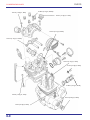
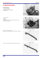
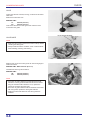
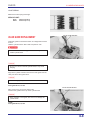
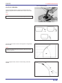
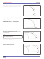
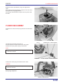
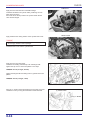
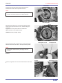
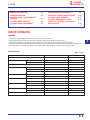
6.
XL200
SERVICE INFORMATION
TROUBLESHOOTING
CYLINDER HEAD COVER/CAMSHAFT
REMOVAL
CYLINDER HEAD REMOVAL
CYLINDER HEAD DISASSEMBLY
6-1
6-2
CYLINDER
HEAD/VALVES
VALVE GUIDE REPLACEMENT
VALVE SEAT INSPECTION/REFACING
CYLINDER HEAD ASSEMBLY
CYLINDER HEAD INSTALLATION
CAMSHAFT/CYLINDER HEAD COVER
INSTALLATION
6-3
6-6
6-7
6-9
6-10
6-13
6-14
6-15
SERVICE INFORMATION
GENERAL
• This section covers service procedure for the cylinder head and valves.
• The engine must be removed to service the camshaft, cylinder head, valves and rocker arms.
• Camshaft and rocker arm lubrication oil is fed through an oil passage. Be sure the passage is not clogged.
• Clean all disassembled parts with clean solvent and dry them by blowing them off with compressed air before inspection.
• Pour clean engine oil into the oil pockets in the cylinder head during assembly to lubricate the camshaft lobes.
SPECIFICATIONS
UNIT: mm (in)
ITEM
1.350 kPa (13.5 kg/cm ; 192 psi).
—
IN.
31.579 - 31.739 (1.243-1.249)
31.30 (1.232)
EX
31.419 - 31.579 (1.236-1.243)
31.20 (1.228)
—
0.10 (0.004)
I.D.
12.000 - 12.018 (0.4724 - 0.4731)
12.05 (0.474)
Shaft O.D.
11.977 - 11.995 (0.4715 - 0.4722)
11.93 (0.470)
Arm-to-shaft clearance
0,005 - 0,041 (0.0002 - 0.0016)
0.08 (0.003)
INNER
39.2 (1.543)
38.0 (1.50)
OUTER
44.85 (1.766)
43.5 (1.71)
Cylinder head warpage
Rocker arm
Valve spring free length
Valve stem O.D.
Valve guide I.D.
Stem-to-guide clearance
Valve seat width
SERVICE LIMIT
2
Cylinder compression
Cam lobe height
STANDARD
IN
5.450 - 5.465 (0.2146 - 0.2152)
5.44 (0.214)
EX
5.430 - 5.445 (0.2138 - 0.2144)
5.42 (0.213)
IN
5.475 - 5.485 (0.2156 - 0.2159)
5.50 (0.217)
EX
5.475 - 5.485 (0.2156 - 0.2159)
5.50 (0.217)
IN
0.010 - 0.035 (0.0004 - 0.0014)
0.06 (0.002)
EX
0.030 - 0.055 (0.0012 - 0.0022)
0.08 (0.003)
1.1 - 1.3 (0.043-0.051)
1.5 (0.06)
6–1
6
XL200
CYLINDER HEAD/VALVES
10 N.m (1.0 kg.m, 7ft-lb)
27 N.m (2.7 kg.m, 20ft-lb)
15 N.m (1.5 kg.m, 11ft-lb)
12 N.m (1.2 kg.m, 9ft-lb)
14 N.m (1.4 kg.m, 10ft-lb)
10 N.m (1.0 kg.m, 7ft-lb)
4 N.m (0.4 kg.m, 3ft-lb)
12 N.m (1.2 kg.m, 9ft-lb)
10 N.m (1.0 kg.m, 7ft-lb)
8 N.m (0.8 kg.m, 6ft-lb)
6 N.m (0.6 kg.m, 4ft-lb)
6-0
XL200
CYLINDER HEAD/VALVES
TORQUE VALUES
Valve adjusting hole cap
Valve adjusting screw lock nut
Cylinder head cover 8 mm cap nut
Cylinder head cover 6 mm socket bolt
Cam sprocket bolt
Cam chain tensioner lifter mounting bolt
Cam chain tensioner lifter sealing screw
Timing hole cap
Crankshaft hole cap
15 N.m (1,5 kg.m, 11 ft-lb)
14 N.m (1,4 kg.m, 10 ft-lb)
27 N.m (2,7 kg.m, 20 ft-lb)
10 N.m (1,0 kg.m, 7 ft-lb)
12 N.m (1,2 kg.m, 9 ft-lb)
12 N.m (1,2 kg.m, 9 ft-lb)
4 N.m (0,4 kg.m, 3 ft-lb)
6 N.m (0,6 kg.m. 4 ft-lb)
8 N.m (0,8 kg.m, 6 ft-lb)
TOOLS
Valve guide reamer, 5.485 mm
Valve guide driver, 5,5 mm
Valve spring compressor
07984-0980001
07742-0010100BR
07757-0010000BR
TROUBLESHOOTING
• Engine top-end problems usually affect engine performance. These can be diagnosed by a compression or leak down test,
or by tracing noises to the top-end with a sounding rod or stethoscope.
• If the performance is poor at low speeds, check for white smoke in the crankcase breather tube. If the tube is smoky, check
for a seized piston ring.
Compression too low, hard starting or poor performance at low speed
• Valves
– Incorrect valve adjustment
– Burned or bent valves
– Incorrect valve timing
– Broken valve spring
– Weak valve spring
• Cylinder head
– Leaking or damaged cylinder head gasket
– Warped or cracked cylinder head
• Faulty cylinder/piston (Section 7)
Compression too high, overheating or knocking
• Excessive carbon build-up in cylinder or on top of
piston
6-2
Excessive smoke
• Worn valve stem or valve guide
• Damaged stem seal
• Faulty cylinder or piston (Section 7)
Excessive noise
• Incorrect valve clearance
• Sticking valve or broken valve spring
• Worn or damaged push rod
• Loose or worn cam chain
• Worn or damaged cam chain tensioner
• Worn cam sprocket teeth
• Worn rocker arm and/or shaft
• Faulty cylinder or piston (Section 7)
Rough idle
• Low cylinder compression
• Intake air leak
XL200
CYLINDER HEAD/VALVES
BOLTS
CYLINDER HEAD COVER/CAMSHAFT
REMOVAL
Remove the following:
– starter motor
– crankshaft/timing hole caps
Remove the bolts, cam chain tensioner lifter and gasket.
CAM CHAIN TENSIONER
INDEX MARK
Align the “T” mark on the flywheel with the index mark on the left
crankcase cover by turning the crankshaft counterclockwise.
“T” MARK
CAM SPROCKET COVER
Remove the valve adjusting hole caps and make sure the piston
is at T.D.C. on the compression stroke by checking for clearance
at both rocker arms.
If the piston is not at T.D.C. on the compression stroke, rotate the
crankshaft 360 degrees counterclockwise and recheck.
Remove the cam sprocket cover.
Remove the cam sprocket bolts by holding the crankshaft.
BOLTS
Remove the cam sprocket from the camshaft flange, then remove
the cam chain from the sprocket.
NOTE
• Suspend the cam chain with a piece of wire to prevent it
from falling into the crankcase.
CAM SPROCKET
CAM CHAIN
6-3
XL200
CYLINDER HEAD/VALVES
CAP NUT/SEALING WASHER
Remove the engine hanger plate.
Remove the cylinder head cover cap nuts/sealing washers and
flange bolts in a gradual, crisscross pattern.
Remove the cylinder head cover.
HEAD COVER
CAMSHAFT
BOLTS
DOWEL PIN
Remove the camshaft.
Remove the dowel pins.
NOTE
• It is not necessary to force them out.
RUBBER PLUG
Remove the rubber plug; do not lose it.
Clean off any sealant material from the head cover and cylinder
head mating surface.
CAMSHAFT INSPECTION
Turn the outer races of camshaft bearings with your finger.
The bearings should turn smoothly and quietly.
Also check that the inner races fit tightly on the camshaft.
Measure the height of each cam lobe and inspect it for wear or
damage.
SERVICE LIMIT:
Intake:
Exhaust:
6-4
31.30 mm (1.232 in)
31.20 mm (1.228 in)
XL200
CYLINDER HEAD/VALVES
TENSIONER LIFTER
TENSIONER LIFTER INSPECTION
Remove the cam chain tensioner lifter sealing bolt and O-ring.
Check the lifter operation:
– the tensioner shaft should not go into the body unless it is
pushed.
– When it turned clockwise with a screwdriver, the tensioner
shaft shoud be pulled into the body. The shaft should spring
out of the body as soon as the screwdriver is released.
Make a tensioner shaft stopper tool out of a thin piece of steel
(0.8 mm thick) using the diagram.
PLATE
(0.8 mm thick)
CYLINDER HEAD COVER DISASSEMBLY
Remove the rocker arm shaft plate by removing the setting
screw.
SCREW
ROCKER ARM SHAFT
ROCKER ARM
Remove the rocker arm shafts by screwing a 6 mm bolt into the
threaded ends as shown.
Remove the rocker arms.
ROCKER ARM/SHAFT INSPECTION
Inspect the rocker arm slipper surfaces for excessive wear.
Inspect the rocker arms and shafts for wear or damage.
6 mm BOLT
ROCKER ARM
ROCKER ARM SHAFT
NOTE
• If the rocker arms require servicing or replacement, inspect
the cam lobes for scoring, chipping or flat spots.
Measure the I.D. of each rocker arm.
SERVICE LIMIT: 12.05 mm (0.474 in)
Measure the O.D. of each rocker arm shaft.
SERVICE LIMIT: 11.93 mm (0.470 in)
Calculate the rocker arm-to-shaft clearance.
SERVICE LIMIT: 0.08 mm (0.003 in)
6-5
XL200
CYLINDER HEAD/VALVES
CYLINDER HEAD
SOCKET BOLT/WASHER
CYLINDER HEAD REMOVAL
Remove the following:
– cylinder head cover
– engine from the frame
– cylinder head socket bolt/washer
– cylinder head
GASKET
DOWEL PIN
– cam chain guide
– gasket
– dowel pins
Clean off any gasket material from the cylinder head and
cylinder mating surfaces.
CAM CHAIN GUIDE
CAM CHAIN TENSIONER
Remove the cam chain tensioner.
Check the cam chain tensioner for excessive wear or damage.
CAM CHAIN GUIDE
Check the cam chain guide for excessive wear or damage.
6-6
XL200
CYLINDER HEAD/VALVES
PIVOT BOLT/WASHER
SOCKET BOLT
CYLINDER HEAD DISASSEMBLY
Remove the cam chain tensioner pivot bolt, washer and cam
chain tensioner.
Remove the socket bolts and carburetor insulator.
CAM CHAIN TENSIONER
INSULATOR
While compressing the valve spring with a valve spring
compressor, remove the valve cotters.
h
• To prevent loss of tension, do not compress the valve spring
more than necessary to remove the cotters.
TOOL:
Valve spring compressor
SPRING COMPRESSOR
VALVE
SPRING SEAT
INNER SPRING
Loosen the valve spring compressor and remove the following:
– spring retainers
– outer and inner valve springs
– spring seats
– inlet and exhaust valve
NOTE
• Mark all disassembled parts to ensure correct reassembly.
Remove the carbon deposits from the combustion chamber.
Clean off any gasket materials from the cylinder head surface.
STEM SEAL
OUTER SPRING
SPRING RETAINER
INSPECTION
CYLINDER HEAD
Check the spark plug hole and valve area for cracks.
Check the cylinder head for warpage with a straight edge and a
feeler gauge.
SERVICE LIMIT: 0.10 mm (0.004 in)
6-7
XL200
CYLINDER HEAD/VALVES
VALVE
Inspect the valve for trueness, burning, scratches or abnormal
stem wear.
Measure the valve stem O.D.
SERVICE LIMIT:
In:
5.44 mm (0.214 in)
Ex:
5.42 mm (0.213 in)
Insert each valve into the valve guide and check the valve
movement in the guide.
VALVE GUIDE REAMER
VALVE GUIDE
NOTE
• Ream the valve guide to remove the carbon build-up before
checking the valve guide.
• Always rotate the reamer clockwise, never couterclockwise
when installing, removing and reaming.
Measure and record each valve guide I.D. with a ball gauge or
inside micrometer.
SERVICE LIMIT: IN/EX: 5.50 mm (0.217 in)
Calculate the stem-to-guide clearance.
SERVICE LIMIT:
IN:
0.06 mm (0.002 in)
EX:
0.08 mm (0.003 in)
NOTE
• If the stem-to-guide clearance exceeds the service limit,
determine if a new guide with standard dimensions would
bring the clearance within tolerance. If so, replace the
guides as necessary and ream to fit.
• If the stem-to-guide clearance still exceeds the service limit
with new guides, replace the valve guide reamers
• Reface the valve seat whenever new valve guides are
installed.
6-8
XL200
CYLINDER HEAD/VALVES
VALVE SPRING
Measure the valve spring free length.
SERVICE LIMIT:
Inner:
Outer:
38.0 mm (1.50 in)
43.5 mm (1.71 in)
VALVE GUIDE DRIVER
VALVE GUIDE REPLACEMENT
Chill valve guides in the freezer section of a refrigerator for about
an hour.
Heat the cylinder head to 100°C with a hot plate or oven.
t
• To avoid burns, wear heavy gloves when handling the
heated cylinder head.
h
• Do not use a torch to heat the cylinder head; it may cause
warping.
Support the cylinder head and drive out the valve guide from the
valve port with a valve guide driver.
h
• Avoid damaging the cylinder head.
TOOL:
Valve guide driver, 5.5 mm
VALVE GUIDE DRIVER
Place a new O-ring on the new valve guide.
Install a valve guide from the top of the cylinder head.
h
• When installing a valve guide, take care not to damage the
cylinder head.
TOOL:
Valve guide driver, 5,5 mm
6-9
XL200
CYLINDER HEAD/VALVES
VALVE GUIDE REAMER
After driving in the valve guide, ream it with a valve guide
reamer.
NOTE
• Use cutting oil on the reamer during this operation.
• Always rotate the reamer clockwise, never
counterclockwise.
Clean the cylinder head thoroughly to remove any metal particles.
Reface the valve seat.
VALVE SEAT INSPECTION/REFACING
VALVE SEAT INSPECTION
Clean the intake and exhaust valves thoroughly to remove the
carbon deposits.
Apply light coating if Prussian Blue to the valve seats.
Lap the valves and seats using a rubber hose or other hand
lapping tool.
Remove the tool and inspect the width of each valve seat.
STANDARD: 1.1 - 1.3mm (0.04 - 0.05 in)
SERVICE LIMIT: 1.5 mm (0.06 in)
(1) SEAT WIDTH
If the valve seat is too wide, too narrow or has low spots, the seat
must be ground.
h
• The valve cannot be ground. If a valve face is burned or
badly worn or it contact the seat unevenly, replace the valve.
6-10
XL200
CYLINDER HEAD/VALVES
VALVE GUIDE REAMER
VALVE SEAT GRINDING
Honda Valve Seat Cutters, a grinder or equivalent valve seat
refacing equipament are recommended to correct a worn valve
seat.
NOTE
• Follow the refacer manufacturer’s operating instructions.
Use a 45 degree cutter to remove ant roughness or irregularities
from the seat.
NOTE
• Reface the valve seat with a 45 degree cutter when a valve
guide is replaced.
Using 32 degree cutter, remove 1/4 of the exiting valve seat
material.
6-11
CYLINDER HEAD/VALVES
Using 60 degree cutter, remove the bottom 1/4 of the oil seat.
Remove the cutter and inspect the area you have just removed.
Install a 45 degree finish cutter and cut the seat to proper width.
Make sure that all pitting and irregularities are removed.
Refinish if necessary.
STANDARD SEAT WIDTH: 1.1 - 1.3 mm (0.04-0.05 in)
Apply thin coat of Prussian Blue to the valve seat.
Press the valve through the valve guide and onto the seat to
make a clear pattern.
NOTE
• The location of the valve seat in relation to the valve face is
very important for good sealing.
If the contact area is too high on the valve, the seat must be
lowered using a 32 degree flat cutter.
If the contact area is too low on the valve, the seat must be
raised using a 60 degree inner cutter.
6-12
XL200
XL200
CYLINDER HEAD/VALVES
Refinish the seat to specifications, using a 45 degree finish
cutter.
After cutting the seat, apply lapping compound to the valve face,
and lap the valve using light pressure.
After lapping, wash all residual compound off the cylinder head
and valve.
STEM SEAL
CYLINDER HEAD ASSEMBLY
Install the inner and outer valve spring seats and new valve stem
seals.
VALVE
SPRING SEAT INNER SPRING
Lubricate each valve stem with engine oil.
Insert the intake and exhaust valve into the valve guides.
Install the valve spring seats, springs and retainers.
NOTE
• Install the valve springs with the narrow pitch end facing the
combustion chamber.
STEM SEAL
OUTER SPRING
SPRING RETAINER
Compress the valve spring and install the valve cotters.
h
• To prevent loss of tension, do not compress the valve spring
more than necessary.
TOOL:
Valve spring compressor
SPRING COMPRESSOR
6-13
XL200
CYLINDER HEAD/VALVES
Tap the stems gently with a plastic hammer to firmly seat the
cotters.
h
• Support the cylinder head above the work bench surface to
prevent valve damage.
O-RING
Check the insulator O-ring is in good condition, replace if
necessary.
Tighten the insulator socket bolt securely.
INSULATOR
PIVOT BOLT/WASHER
SOCKET BOLT
Install the cam chain tensioner, washer and pivot bolt.
Tighten the pivot bolt to the specified torque.
TORQUE: 10 N.m (1.0 kg.m, 7 ft-lb)
CAM CHAIN TENSIONER
CAM CHAIN GUIDE
CYLINDER HEAD INSTALLATION
Place the bottom end of the cam chain guide into the groove in
the left crankcase, and its bosses in the grooves in the cylinder
upper surface.
NOTE
• Make sure that the cam chain is properly installed on the
timing sprocket as shown.
ALIGN
6-14
XL200
CYLINDER HEAD/VALVES
DOWEL PIN
GASKET
Clean the cylinder head gasket surface of any gasket materials.
NOTE
• Do not allow dust and dirt to enter the engine.
Install the dowel pins, new O-ring and new cylinder head gasket.
CYLINDER HEAD
Install the cylinder head
Install a new sealing washer and the tensioner pivot bolt through
the tensioner hole.
Tighten the bolt to the specified torque.
TORQUE: 10 N.m (1.0 kg.m, 7 ft-lb)
SOCKET BOLT/WASHER
ROCKER ARM
ROCKER ARM SHAFT
CAMSHAFT/CYLINDER HEAD COVER
INSTALLATION
CYLINDER HEAD COVER ASSEMBLY
Apply oil to the rocker arm shafts.
Install the rocker arms and rocker arm shafts in the cylinder head
cover.
With the rocker arm shaft reliefs on the inside, install the rocker
arm shaft plate.
Tighten the setting screw securely.
SCREW
PLATE
CAMSHAFT/CYLINDER HEAD COVER INSTALLATION
Install the dowel pins and rubber plug.
RUBBER PLUG
DOWEL PINS
6-15
XL200
CYLINDER HEAD/VALVES
CAMSHAFT
Apply oil to the cam lobes and camshaft bearings.
Install the camshaft in the cylinder head, positioning the cam
lobes down as shown.
Pour fresh oil into the oil pocket in the cylinder head until the
cams are submerged.
HEAD COVER
Apply sealant to the mating surface of the cylinder head cover.
h
• Do not apply sealant to the oil passage.
Install the head cover onto the cylinder head.
SEALANT
Apply oil to the cap nut threads.
Install the new sealing washers/cap nuts and flange bolts.
Tighten the cap nut in a crisscross pattern in 2-3 steps.
CAP NUT/WASHER
TORQUE: 27 N.m (2.7 kg.m, 20 ft-lb)
Tighten the flange bolts and setting bolt in a gradual crisscross
pattern.
TORQUE: 10 N.m (1.0 kg.m, 7 ft-lb)
BOLT
Align the “T” mark on the flywheel with the index mark on the left
crankcase cover by turning the crankshaft counterclockwise.
(1) INDEX MARK
(2) “T” MARK
6-16
XL200
CYLINDER HEAD/VALVES
CAM CHAIN
Install the cam sprocket with its timing marks facing out.
Install the cam chain over the sprocket as shown.
NOTE
• If it is difficult to install the chain over the sprocket, make
sure the chain is set properly on the timing sprocket.
CAM SPROCKET
BOLTS
Align the timing marks on the cam sprocket with the mating
surface of the cylinder head and cover, without rotating the
crankshaft.
Apply oil to the cam sprocket bolts and install them.
Tighten the bolts to the specified torque.
TORQUE: 12 N.m (1.2 kg.m, 9 ft-lb)
TIMING MARKS
TENSIONER LIFTER
SCREWDRIVER
Turn the tensioner shaft clockwise with a small screwdriver to
retract the tensioner, and hold it in the fully retracted position.
NOTE
• The tensioner will forced out by the spring when it is
released.
Wedge the tensioner shaft with a piece of wire to hold the
tensioner.
GASKET
TENSIONER LIFTER
Install a new gasket on the cam chain tensioner lifter and install
it.
6-17
XL200
CYLINDER HEAD/VALVES
SOCKET BOLT
SCREW
Tighten the cam chain tensioner lifter mounting bolts.
TORQUE: 12 N.m (1.2 kg.m, 9 ft-lb)
Remove the wire holder piece from the tensioner lifter.
Install and tighten the screw with a new O-ring.
Tighten the screw to the specified torque.
TORQUE: 4 N.m (0.4 kg.m, 3 ft-lb)
Rotate the crankshaft counterclockwise a few times and recheck
the valve timing.
O-RING
Install a new gasket and O-ring onto the sprocket cover.
Install the sprocket cover with its oil pocket facing down as
shown.
Install and tighten the cover bolts securely.
Apply clean engine oil to the O-rings of the adjusting hole caps.
CAM SPROCKET COVER
BOLTS
Install and tighten the cap bolts.
TORQUE: 15 N.m (1.5 kg.m, 11 ft-lb)
TIMING HOLE CAP
Install and tighten the timing hole cap and crankshaft hole cap.
TORQUE:
Timing hole cap:
6 N.m (0.6 kg.m, 4 ft-lb)
Crankshaft hole cap: 8 N.m (0.8 kg.m, 6 ft-lb)
Install the following:
– starter motor
– engine
CRANKSHAFT HOLE CAP
6-18
XL200
CYLINDER HEAD/VALVES
NOTAS
6-19
GENERAL INFORMATION
HOW TO USE THIS MANUAL
CONTENTS
This service manual describes the service
procedure for the XL200.
• Throughout the manual, the following
abbreviations are used to identify individual
models.
Code
DK
2LA
Area (type)
General Type
Latin America
Follow the Maintenance Schedule (Section 3)
recommendations to ensure that the vehicle is in
peak operation condition.
Section 1 through 3 apply to the whole motorcycle,
while section 4 through 18 describe parts of the
motorcycle, grouped according to location.
ENGINE
Performing the first scheduled maintenance is very
important. It compensates for the initial wear that
occurs during the break-in period.
GENERAL INFORMATION
1
LUBRICATION
2
MAINTENANCE
3
FUEL SYSTEM
4
ENGINE REMOVAL/INSTALLATION
5
CYLINDER HEAD/VALVES
6
CYLINDER/PISTON
7
CLUTCH/GEARSHIFT LINKAGE
8
ALTERNATOR/STARTER CLUTCH
9
Find the section you want on this page, then turn to
the table of contents on page 1 of that section.
Most sections start with an assembly or system
illustration, service information and troubleshooting
for the section, the subsequent pages give detailed
procedures.
ELECTRIC STARTER
All information, illustrations, directions and
specifications included in this publication are
based on the latest product information available
at the time of approval for printing. MOTO
HONDA DA AMAZÔNIA LTDA. Reserves the
right to make changes at any time without notice
and without incurring any oblication whatever.
Not part of this publication may be reproduced
without written permission.
FRAME
If you don’t know the source of the trouble, go to
section 20 TROUBLESHOOTING.
CRANKSHAFT/KICKSTARTER/
TRANSMISSION
10
FRONT WHEEL/SUSPENSION/STEERING
11
REAR WHEEL/SUSPENSION
12
HYDRAULIC BRAKE
13
FAIRING/EXHAUST SYSTEM
14
CHARGING SYSTEM
15
IGNITION SYSTEM
16
ELECTRIC STARTER
17
LIGHTS/METERS/SWITCHES
18
WIRING DIAGRAM
19
TROUBLESHOOTING
20