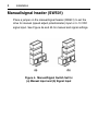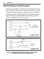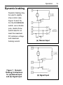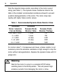
1
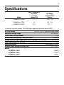
USER’S MANUAL
PCMXP Series
Isolated Input, Pulse-Width Modulated,
Adjustable Speed Drives
for DC Brush Motors
Models: PCMXP02–115AC
PCMXP05–115AC
PCMXP10–115AC
Copyright © 2013 by
Minarik Drives
All rights reserved. No part of this document may be reproduced or transmitted in
any form without written permission from Minarik Drives. The information and
technical data in this document are subject to change without notice. Minarik
Drives makes no warranty of any kind with respect to this material, including, but
not limited to, the implied warranties of its merchantability and fitness for a given
purpose. Minarik Drives assumes no responsibility for any errors that may appear in
this document and makes no commitment to update or to keep current the information
information in this document.
Printed in the United States of America.
i
Safety Warnings
•
This symbol
denotes an important safety tip or warning.
Please read these sections carefully prior to performing any of
the instructions contained in that section.
•
Have a qualified electrical maintenance technician install, adjust
and service this equipment. Follow the National Electrical Code
and all other applicable electrical and safety codes, including the
provisions of the Occupational Safety and Health Act (OSHA),
when installing equipment.
•
Reduce the chance of an electrical fire, shock, or explosion by
proper grounding, over-current protection, thermal protection,
and enclosure. Follow sound maintenance procedures.
It is possible for a drive to run at full speed as a result of
a component failure. Minarik strongly recommends the
installation of a master switch in the main power input to stop
the drive in an emergency.
Circuit potentials are at 115 VAC above earth ground.
Avoid direct contact with the printed circuit board or with
circuit elements to prevent the risk of serious injury or fatality.
Use a non-metallic screwdriver for adjusting the calibration
trimpots. Use approved personal protective equipment and
insulated tools if working on this drive with power applied.
ii
Contents
Safety Warnings . . . . . . . . . . . . . . . . . . . . . . . . . . . . . . . . . . . . . . . . .i
Specifications
. . . . . . . . . . . . . . . . . . . . . . . . . . . . . . . . . . . . . . . . .1
Dimensions . . . . . . . . . . . . . . . . . . . . . . . . . . . . . . . . . . . . . . . . . . . .2
Installation
Mounting
. . . . . . . . . . . . . . . . . . . . . . . . . . . . . . . . . . . . . . . . . . . .3
. . . . . . . . . . . . . . . . . . . . . . . . . . . . . . . . . . . . . . . . . . . . . . . . .3
Wiring . . . . . . . . . . . . . . . . . . . . . . . . . . . . . . . . . . . . . . . . . . . . . . . . . . . . .4
Heat sinking . . . . . . . . . . . . . . . . . . . . . . . . . . . . . . . . . . . . . . . . . . . . . . . .6
Line fusing . . . . . . . . . . . . . . . . . . . . . . . . . . . . . . . . . . . . . . . . . . . . . . . . .6
Speed adjust potentiometer . . . . . . . . . . . . . . . . . . . . . . . . . . . . . . . . . . . .7
Manual/signal header (SW501)
. . . . . . . . . . . . . . . . . . . . . . . . . . . . . . . . .8
Connections . . . . . . . . . . . . . . . . . . . . . . . . . . . . . . . . . . . . . . . . . . . . . . . .9
Operation . . . . . . . . . . . . . . . . . . . . . . . . . . . . . . . . . . . . . . . . . . . . .10
Before applying power:
. . . . . . . . . . . . . . . . . . . . . . . . . . . . . . . . . . . . . .10
Startup . . . . . . . . . . . . . . . . . . . . . . . . . . . . . . . . . . . . . . . . . . . . . . . . . . .10
Line starting and line stopping
. . . . . . . . . . . . . . . . . . . . . . . . . . . . . . . . .11
Automatic restart upon power restoration . . . . . . . . . . . . . . . . . . . . . . . . .11
Decelerating to minimum speed . . . . . . . . . . . . . . . . . . . . . . . . . . . . . . . .12
Dynamic braking
. . . . . . . . . . . . . . . . . . . . . . . . . . . . . . . . . . . . . . . . . . .13
Calibration . . . . . . . . . . . . . . . . . . . . . . . . . . . . . . . . . . . . . . . . . . . .15
MINIMUM SPEED (MIN SPD)
. . . . . . . . . . . . . . . . . . . . . . . . . . . . . . . . .16
MAXIMUM SPEED (MAX SPD) . . . . . . . . . . . . . . . . . . . . . . . . . . . . . . . .16
CURRENT LIMIT (CURR LIMIT) . . . . . . . . . . . . . . . . . . . . . . . . . . . . . . . .17
IR COMPENSATION (IR COMP) . . . . . . . . . . . . . . . . . . . . . . . . . . . . . . .18
SIGNAL ADJUST (SIG ADJ)
. . . . . . . . . . . . . . . . . . . . . . . . . . . . . . . . . .18
iii
Application Notes . . . . . . . . . . . . . . . . . . . . . . . . . . . . . . . . . . . . . .20
Multiple fixed speeds . . . . . . . . . . . . . . . . . . . . . . . . . . . . . . . . . . . . . . . .20
Adjustable speeds using potentiometers in series . . . . . . . . . . . . . . . . . . .21
Independent adjustable speeds . . . . . . . . . . . . . . . . . . . . . . . . . . . . . . . .22
RUN/JOG switch . . . . . . . . . . . . . . . . . . . . . . . . . . . . . . . . . . . . . . . . . . .22
Reversing
. . . . . . . . . . . . . . . . . . . . . . . . . . . . . . . . . . . . . . . . . . . . . . . .24
Reversing with a DIGI-LOK Controller
. . . . . . . . . . . . . . . . . . . . . . . . . . .26
Troubleshooting . . . . . . . . . . . . . . . . . . . . . . . . . . . . . . . . . . . . . . . .27
Before troubleshooting . . . . . . . . . . . . . . . . . . . . . . . . . . . . . . . . . . . . . . .27
Block Diagram . . . . . . . . . . . . . . . . . . . . . . . . . . . . . . . . . . . . . . . . .32
Replacement Parts . . . . . . . . . . . . . . . . . . . . . . . . . . . . . . . . . . . . .34
Unconditional Warranty . . . . . . . . . . . . . . . . . . . . .inside back cover
Tables
Table 1. Recommended Dynamic Brake Resistor Sizes . . . . . . . . . . . . . . . . . .14
Table 2. Replacement Parts . . . . . . . . . . . . . . . . . . . . . . . . . . . . . . . . . . . . . . .34
iv
Illustrations
Figure 1. PCMXP Series Dimensions . . . . . . . . . . . . . . . . . . . . . . . . . . . . . . . . .2
Figure 2. Earth Ground Screw . . . . . . . . . . . . . . . . . . . . . . . . . . . . . . . . . . . . . .4
Figure 3. Speed Adjust Potentiometer . . . . . . . . . . . . . . . . . . . . . . . . . . . . . . . . .7
Figure 4. Manual/Signal Switch Set for
(a) Manual Input and (b) Signal Input . . . . . . . . . . . . . . . . . . . . . . . . . .8
Figure 5. PCMXP Connections . . . . . . . . . . . . . . . . . . . . . . . . . . . . . . . . . . . . . .9
Figure 6. Decelerating to Minimum Speed Connections for
(a) Manual Input and (b) Signal Input . . . . . . . . . . . . . . . . . . . . . . . . .12
Figure 7. Dynamic Braking Connections for
(a) Manual Input and (b) Signal Input . . . . . . . . . . . . . . . . . . . . . . . . .13
Figure 8. Typical CURRENT LIMIT and IR COMP Settings
(actual settings may vary with each application) . . . . . . . . . . . . . . . . .19
Figure 9. Multiple Fixed Speeds . . . . . . . . . . . . . . . . . . . . . . . . . . . . . . . . . . . .20
Figure 10. Adjustable Speeds Using Potentiometers in Series . . . . . . . . . . . . . .21
Figure 11. Independent Adjustable Speeds . . . . . . . . . . . . . . . . . . . . . . . . . . . .22
Figure 12. RUN/JOG Switch for (a) Manual Input and (b) Signal Input . . . . . . . .23
Figure 13. Reversing with Manual Input . . . . . . . . . . . . . . . . . . . . . . . . . . . . . .24
Figure 14. Reversing with Signal Input . . . . . . . . . . . . . . . . . . . . . . . . . . . . . . .25
Figure 15. Reversing with a DLC600 . . . . . . . . . . . . . . . . . . . . . . . . . . . . . . . . .26
Figure 16. PCMXP Block Diagram . . . . . . . . . . . . . . . . . . . . . . . . . . . . . . . . . .32
1
Specifications
Model
Max. Continuous
Armature
Current
(Amps DC)
HP Range
with 130 VDC
Motors
PCMXP02–115AC
2
1/20 – 1/8
PCMXP05–115AC
5
1/4 – 1/2
PCMXP10–115AC
10 †
1/2 – 1
† Use heat sink part number 223–0159 when operating the drive above 5 ADC.
AC Line Voltage
115 VAC, ±10%, 50/60 Hz, single phase
Armature Voltage Range
0–130 VDC
Form Factor (at base speed)
1.05
Acceleration/Deceleration Time (with load)
1 second
Analog Input Voltage Range (input circuit isolated; POS to NEG)
Input Impedance (POS to NEG)
Speed Regulation
Ambient Temp. Range (chassis drive)
0–10 VDC
> 2 KΩ
1% base speed or better
10°C – 40°C
Weight
PCMXP02–115AC
0.68 lb
PCMXP05–115AC
0.75 lb
PCMXP10–115AC
0.82 lb
2
Dimensions
Model
PCMXP02–115AC
PCMXP05–115AC
PCMXP10–115AC
Dimension “A”
1.77 [45]
2.36 [60]
2.88 [73]
SIX MOUNTING SLOTS 0.19 [5] WIDE x 0.34 [9] DEEP
ALL DIMENSIONS IN INCHES [MILLIMETERS]
Figure 1. PCMXP Series Dimensions
3
Installation
Mounting
• Drive components are sensitive to electrostatic fields. Avoid
contact with the circuit board directly. Hold drive by the chassis
only.
• Protect the drive from dirt, moisture, and accidental contact.
Provide sufficient room for access to the terminal block and
calibration trimpots.
• Mount the drive away from other heat sources. Operate the drive
within the specified ambient operating temperature range.
• Prevent loose connections by avoiding excessive vibration of the
drive.
• Mount drive with its board in either a horizontal or vertical plane.
Six 0.19 in. (5 mm) wide slots in the chassis accept #8 pan head
screws. Fasten either the large base or the narrow flange of the
chassis to the subplate.
4
Installation
Wiring
Warning
Do not install, remove, or rewire this equipment with power
applied. Failure to heed this warning may result in fire,
explosion, or serious injury.
This drive is isolated from earth ground. Circuit potentials are at
at 115 above ground. To prevent the risk of injury or fatality, avoid
direct contact with the printed circuit board or with circuit elements.
Do not disconnect any of the motor leads from the drive
unless power is removed or the drive is disabled. Opening
any one motor lead mya destroy the drive.
This product does not have internal solid state motor overload
protection. It does not contain speed-sensitive overload protection,
thermal memory retention or provisions to receive and act upon
signals from remote devices for over temperature protection. If
motor overload protection is needed in the end-use product, it
needs to be provided by additional equipment in accordance with
NEC standards.
• Use 18 AWG wire for speed adjust potentiometer or voltage signal
input wiring. Use 16 AWG wire for motor and AC line voltage wiring.
• Connect earth ground to the earth ground screw attached to the PC
board. See Figure 2 for the earth ground screw location.
Earth
Ground
Screw
Figure 2.
Ground Screw
Installation
5
Shielding Guidelines
Warning
Under no circumstances should power and logic leads be
bundled together. Induced voltage can cause unpredictable
behavior any electronic device, including motor controls.
As a general rule, Minarik Drives recommends shielding of all conductors.
If it is not practical to shield power conductors, Minarik Drives
recommends shielding all logic-level leads. If shielding is not
practical, the user should twist all logic leads with themselves to
minimize induced noise.
It may be necessary to earth ground the shielded cable. If noise is
produced by devices other than the drive, ground the shield at the
drive end. If noise is generated by a device on the drive, ground
the shield at the end away from the drive. Do not ground both ends
of the shield.
If the drive continues to pick up noise after grounding the shield, it
may be necessary to add AC line
devices, or to mount the
drive in a less noisy environment.
Logic wires from other input devices, such as motion controllers
and PLL velocity controllers, must be separated from power lines in
the same manner as the logic I/O on this drive.
6
Installation
Heat sinking
Model PCMXP10-115AC requires an additional heat sink when the
continuous armature current is above 5 ADC. Use Minarik part
number 223-0159. All other chassis drives have sufficient heat
sinking in their basic configurations. Use a thermally conductive
heat sink compound (such as Dow Corning® 340 Heat Sink
Compound) between the drive chassis and heat sink surface for
optimum heat transfer.
Line fusing
Protect all PCMXP Series drives with AC line fuses. Use fast acting
AC line fuses rated for 250 volts, and approximately
150% to 200% of the maximum armature current. Fuse only the
“hot” side of the AC line (L1) if using 115 VAC line voltage.
See the chart below for recommended line fuse sizes:
Line Fuse Chart
Maximum Armature
AC Line Fuse
Current (DC Amps)
Rating (AC Amps)
0.5
1
0.8
1.5
1.5
3
2.6
5
3.5
8
5.0
10
7.6
15
10
15
Installation
Speed adjust potentiometer
Mount the speed adjust potentiometer through a 0.38 in. (10 mm)
hole with the hardware provided (Figure 3). Install the circular
insulating disk between the panel and the 10K ohm speed adjust
potentiometer. Twist the speed adjust potentiometer wire to avoid
picking up unwanted electrical noise. If potentiometer leads are
longer than 18 in. (457 mm), use shielded cable (see Wiring
section).
Warning
Be sure that the potentiometer tabs do not make contact with
the potentiometer enclosure. Grounding the input will cause
damage to the drive.
Figure 3. Speed Adjust Potentiometer
7
8
Installation
Manual/signal header (SW501)
Place a jumper on the manual/signal header (SW501) to set the
drive for manual (speed adjust potentiometer) input or 0–10 VDC
signal input. See Figure 4a and 4b for manual and signal settings.
(a)
(b)
Figure 4. Manual/Signal Switch Set for
(a) Manual Input and (b) Signal Input
Installation
9
Connections
The PCMXP Series drives supply motor voltage to terminals A1 and A2
(A1 is positive with respect to A2). It is assumed throughout this manual
that the driven motor will rotate clockwise (CW) while looking at the
output shaft protruding from the front of the motor. If the opposite is
desired, simply reverse the wiring of A1 and A2 with each other.
Figure 5. PCMXP Connections
10
Operation
Warning
Dangerous voltages exist on the drive when it is powered,
and up to 30 seconds after power is removed and the motor
stops. BE ALERT. High voltages can cause serious or fatal
injury. For your safety, use personal protective equipment
(PPE) when operating this drive.
Before applying power
1. Verify that no conductive material is present on the printed
circuit board.
2. Ensure that all jumpers are properly set.
Startup
1. Turn the speed adjust potentiometer full counterclockwise
(CCW). If the drive follows a voltage signal, set the voltage
signal to 0 VDC.
2. Apply AC line voltage.
3. Slowly advance the speed adjust potentiometer clockwise (CW).
If a voltage signal is used, slowly increase the voltage signal.
The motor slowly accelerates as either the potentiometer is
turned CW, or the voltage signal is increased. Continue until the
desired speed is reached.
Operation
11
4. Remove AC line voltage from the drive to coast the motor to a
stop.
If the motor or drive does not perform as described, disconnect the
AC line voltage immediately. Refer to the Troubleshooting section,
page 28, for further assistance.
Line starting and line stopping
Line starting and line stopping (applying and removing AC line
voltage) is recommended for infrequent starting and stopping of
a drive only. When AC line voltage is applied to the drive, the motor
accelerates to the speed set by the speed adjust potentiometer.
When AC line voltage is removed, the motor coasts to a stop.
Automatic restart upon power restoration
All drives automatically run to set speed when the AC line voltage
is applied. Wiring a latching relay into the AC line is one way to
prevent restarting following a power outage.
12
Operation
Decelerating to minimum speed
A switch may be added to the drive’s input to decelerate the motor
from set speed to minimum speed. See Figure 6a and 6b for switch
connections for both manual and signal input. Close the switch to
decelerate the motor from set speed to minimum speed (minimum
speed is determined by the MIN SPD trimpot setting). Open the
switch to accelerate the motor to set speed.
(a) Manual Input
(b) Signal Input
Figure 6. Decelerating to Minimum Speed Connections
for (a) Manual Input and (b) Signal Input
Operation
Dynamic braking
Dynamic braking may
be used to rapidly
stop a motor (see
Figure 7a and 7b).
For the RUN/BRAKE
switch, use a double
pole, double throw
switch rated for at
least the maximum
DC armature voltage
and maximum
braking current.
Figure 7. Dynamic
Braking Connections
for (a) Manual Input
and (b) Signal Input
(a) Manual Input
(b) Signal Input
13
14
Operation
Size the dynamic brake resistor according to the motor current
rating (see Table 1). The dynamic brake resistance listed in the
table is the smallest recommended resistance allowed to prevent
possible demagnetization of the motor. The motor stops less
rapidly with higher brake resistor values.
Table 1. Recommended Dynamic Brake Resistor Sizes
Minimum
Motor Armature
Current Rating
Less than 2 ADC
2–3 ADC
3–5 ADC
5–10 ADC
10–17 ADC
Minimum
Dynamic Brake
Resistor Value
1 ohm
5 ohm
10 ohm
20 ohm
40 ohm
Dynamic Brake
Resistor Wattage
1W
5W
10W
20W
50W
For motors rated 1/17 horsepower and lower, a brake resistor is not
necessary since the armature resistance is high enough to stop the
motor without demagnetization. Replace the dynamic brake with 12
gauge wire.
Warning
Wait for the motor to come to a complete STOP before
switching back to the RUN position. This will prevent high
armature currents from damaging the motor or drive.
15
Calibration
Warning
Dangerous voltages exist on the drive when it is powered.
When possible, disconnect the voltage input from the drive
before adjusting the trimpots. If the trimpots must be
adjusted with power applied, use insulated tools and the
appropriate personal protection equipment. BE ALERT.
High voltages can cause serious or fatal injury.
Each drive is factory calibrated to its maximum current rating.
Readjust the calibration trimpot settings to accommodate lower
current rated motors.
All adjustments increase with CW rotation, and decrease with CCW
rotation. Use a non-metallic screwdriver for calibration. Each
trimpot is identified on the printed circuit board.
16
Calibration
MINIMUM SPEED (MIN SPD)
The MIN SPD setting determines the motor speed when the speed
adjust potentiometer is turned full CCW. It is factory set to zero
speed, and can be calibrated with a MANUAL or SIGNAL input.
To calibrate, set the MIN SPD trimpot to full CCW. Turn the speed
adjust potentiometer full CCW, or set the signal input to 0 VDC.
Adjust the MIN SPD trimpot until the desired minimum motor speed
is reached.
MAXIMUM SPEED (MAX SPD)
The MAX SPD setting determines the motor speed when the speed
adjust potentiometer is turned full CW. It is factory set for maximum
rated speed, and can only be calibrated with a MANUAL (speed
adjust potentiometer) input.
To calibrate, set the MAX SPD trimpot full CCW. Turn the speed
adjust potentiometer full CW. Adjust the MAX SPD trimpot until the
desired maximum motor speed is reached.
Note: Check the MIN SPD and MAX SPD adjustments after
recalibrating to verify that the motor runs at the desired minimum
and maximum speed.
Calibration
17
CURRENT LIMIT (CURR LIMIT)
Warning
Although Current Limit can be set to 120% of motor
nameplate current rating, continuous operation beyond this
rating may damage the motor. If you intend to operate
beyond this rating, contact your Minarik representative for
assistance.
The CURR LIMIT setting determines the maximum armature current
output of the drive. It is factory set at 120% of rated motor current.
Recalibrate the CURR LIMIT setting when using a lower
horsepower motor. Refer to the recommended CURR LIMIT
settings in Figure 8, or recalibrate using the following procedure:
1. With the power disconnected from the drive, connect a DC
ammeter (0–15 A minimum scale) in series with the armature.
2. Set the CURR LIMIT trimpot to minimum (full CCW).
3. Lock the motor armature. Be sure that the motor is firmly mounted.
4. Connect power to the drive. The motor should remain stopped.
5. Set the speed adjust potentiometer to maximum (full CW).
6. Adjust the CURR LIMIT trimpot CW slowly until the armature
current is 120% of motor rated armature current.
7. Set the speed adjust potentiometer to minimum and remove the
stall from the motor.
8. Remove power from the drive.
9. Remove the stall and the ammeter.
18
Calibration
IR COMPENSATION (IR COMP)
The IR COMP setting determines the degree to which motor speed
is held constant as the motor load changes. It is factory set for
optimum motor regulation.
Recalibrate the IR COMP setting when using a lower horsepower
motor. Refer to the recommended IR COMP settings in Figure 8, or
recalibrate using the following procedure:
If the motor does not maintain set speed as the load changes,
gradually rotate the IR COMP trimpot CW. If the motor oscillates
(overcompensation), the IR COMP trimpot may be set too high
(CW). Turn the IR COMP trimpot CCW to stabilize the drive.
SIGNAL ADJUST (SIG ADJ)
The SIG ADJ setting determines the maximum motor speed when
the signal input is set to the maximum voltage. It is factory set for
maximum rated speed, and can only be calibrated with a SIGNAL
input.
To calibrate, set the signal input to maximum voltage. Adjust the
SIG ADJ trimpot until the motor runs at the desired maximum
motor speed.
Calibration
Figure 8. Typical CURRENT LIMIT and IR COMP Settings
(actual settings may vary with each application)
19
20
Application Notes
Multiple fixed speeds
Replace the speed adjust potentiometer with series resistors
with a total series resistance of 10K ohms (Figure 9). Add a single
pole, multi-position switch with the correct number of positions for
the desired number of fixed speeds.
Figure 9. Multiple Fixed Speeds
Application Notes
Adjustable speeds using potentiometers in
series
Replace the speed adjust potentiometer with a single pole,
multi-position switch, and two or more potentiometers in series,
with a total series resistance of 10K ohms. Figure 10 shows a
connection for fixed high and low speed adjust potentiometers.
Figure 10. Adjustable Speeds Using Potentiometers in Series
21
22
Application Notes
Independent adjustable speeds
Replace the speed adjust potentiometer with a single pole, multiposition switch, and two or more potentiometers in parallel, with a
total parallel resistance of 10K ohms. Figure 11 shows the
connection of two independent speed adjust potentiometers that
can be mounted at two separate operating stations.
Figure 11. Independent Adjustable Speeds
RUN/JOG switch
Using a RUN/JOG switch is recommended in applications where
quick stopping is not needed and frequent jogging is required. Use
a single pole, two position switch for the RUN/JOG switch, and a
single pole, momentary operated pushbutton for the JOG
pushbutton (see Figure 12a and 12b). When the RUN/JOG switch
is set to JOG, the motor decelerates to minimum speed. Press the
JOG pushbutton to jog the motor. Return the RUN/JOG switch to
RUN for normal operation.
Application Notes
23
(a) Manual Input
(b) Signal Input
Figure 12. RUN/JOG Switch for (a) Manual Input and (b) Signal Input
24
Application Notes
Reversing
A dynamic brake may be used when reversing the motor direction
(Figure 13 and 14). Use a three pole, three position switch rated for
at least the maximum DC armature voltage and maximum braking
current. Wait for the motor to stop completely before switching it to
either the forward or reverse direction. See the Dynamic braking
section, page 13, for sizing the dynamic brake resistor.
Figure 13. Reversing with Manual Input
Application Notes
Figure 14. Reversing with Signal Input
25
26
Application Notes
Reversing with a DIGI-LOK Controller
A DIGI-LOK controller, model DLC600 can be used in a reversing
application. The DIGI-LOK must be inhibited while braking.
Without the inhibit feature, the DIGI-LOK will continue to regulate.
This will cause overshoot when the DIGI-LOK is switched back to
the drive.
Figure 15 shows the connection of the reversing circuit to a
PCMXP series drive and a DLC600. Note: Only one DLC option
(Optical Encoder or Magnetic Pickup) may be used at a time.
Figure 15. Reversing with a DLC600
27
Troubleshooting
Warning
Dangerous voltages exist on the drive when it is powered
and up to 30 seconds after power is removed and the motor
stops. When possible, disconnect the AC line voltage from
the drive while troubleshooting. Be alert. High voltages can
cause serious or fatal injury.
Before troubleshooting
Perform the following steps before starting any procedure in this
section:
1. Disconnect AC line voltage from the drive.
2. Check the drive closely for damaged components.
3. Check that no conductive or other foreign material has become
lodged on the printed circuit board.
4. Verify that every connection is correct and in good condition.
5. Verify that there are no short circuits or grounded connections.
6. Check that the manual/signal switch is properly set.
7. Check that the drive’s rated armature outputs are consistent
with the motor ratings.
28
Troubleshooting
Problem
Line fuse blows
Motor runs too fast
at maximum speed
setting
Possible
Causes
Suggested
Solutions
1. Line fuses are the
wrong size.
1. Check that line
fuses are the
correct size.
2. Motor cable or
armature is shorted
to ground.
2. Check motor cable
and armature for
shorts.
3. Nuisance tripping
caused by a
combination of
ambient conditions
and high-current
spikes
(i.e. reversing).
3. Add a blower to
cool the drive
components;
increase FWD TQ
and REV TQ
settings.
1. MIN OUT and
MAX OUT
settings are too
high.
1. Recalibrate MIN
OUT and MAX
OUT.
Troubleshooting
29
Problem
Possible
Causes
Suggested
Solutions
Line fuse is not
blown, but the
motor does not run
1. Speed adjust
potentiometer, or
voltage input signal
is set to zero speed.
1. Increase the speed
adjust
potentiometer, or
voltage setting.
2. Speed adjust pot,
or voltage input
signal, is not
connected to drive
input properly;
connections are
open.
2. Check connections
to input. Verify that
connections are not
open.
3. S2 is shorted to S0.
3. Remove short.
4. Drive is in current
limit.
4. Verify that motor is
not jammed.
Increase the TQ
LIMIT setting. It
may be set too low.
5. Drive is not
receiving AC line
voltage.
5. Apply AC line
voltage to L1 and
L2.
6. Motor is not
connected.
6. Connect motor to
A1 and A2.
30
Troubleshooting
Problem
Possible
Causes
Suggested
Solutions
Motor runs too
slow or too fast
1. MIN OUT and
MAX OUT not
calibrated.
1. Calibrate MIN
OUT and MAX
OUT.
Motor will not
reach the desired
speed
1. MAX OUT setting
is too low.
1. Increase MAX
OUT setting.
2. INPUT ADJ
setting is too low.
2. Recalibrate
INPUT ADJ
setting.
3. IR COMP setting
is too low.
3. Increase the IR
COMP setting.
4. Motor is
overloaded.
4. Check motor load.
Resize the motor
and drive if
necessary.
Troubleshooting
Problem
Motor pulsates or
surges under load
Possible
Causes
31
Suggested
Solutions
1. IR COMP is set
too high.
1. Adjust the IR
COMP setting
slightly CCW until
the motor speed
stabilizes.
2. Motor “bouncing”
in and out of
torque limit.
2. Make sure motor
is not undersized
for load; adjust the
TQ LIMIT
trimpot.
32
33
Block Diagram
Figure 16. PCMXP Block Diagram
32
33
Block Diagram
Figure 16. PCMXP Block Diagram
34
Replacement Parts
Replacement parts are available form Minarik Drives and its
distributors for this drive series.
Table 2. Replacement Parts
Model No
PCMXP02–115AC
Symbol
C501
D501
Q502
R501
R502
TH501
C505
T501
BR601
Description
220 µF, 200 V Capacitor
16 A, 300 V Diode
Power MOSFET
0.2 Ω, 5 W Resistor
3.3K Ω, 10 W Resistor
10 Ω Thermistor
.01 µF, 125 V Capacitor
Transformer
25 A, 600 V Diode Bridge
2 Pin Jumper
10K Ω Potentiometer Kit
Minarik Drives P/N
011–0069
071-0044
070-0043
032-0093
032-0131
033-0005
010-0065
230-0077
073-0009
164-0292
202-0066
PCMXP05–115AC
C501
D501
Q501-502
R501
R502
TH501
C505
T501
BR601
1000 µF, 200 V Capacitor
16 A, 300 V Diode
Power MOSFET
.05 Ω, 5 W Resistor
3.3K Ω, 10 W Resistor
20 A Limiter
.01µF, 125 V Capacitor
Transformer
25 A, 600 V Diode Bridge
2 Pin Jumper
10K Ω Potentiometer Kit
011-0149
071-0050
070-0043
032-0146
032-0131
033-0007
010-0065
230-0077
073-0009
164-0292
202-0066
PCMXP10–115AC
C501
D501
Q501-502
R501
R502
TH501
C505
T501
BR601
1500 µF, 200 V Capacitor
16 A, 300 V Diode
Power MOSFET
.01K Ω, 5 W Resistor
3.3K Ω, 10 W Resistor
20 A Limiter
.01µF, 250 V Capacitor
Transformer
25 A, 600 V Diode Bridge
2 Pin Jumper
10K Ω Potentiometer Kit
011-0143
071-0054
070-0043
032-0129
032-0131
033-0007
010-0065
230-0077
073-0009
164-0181
202-0066
35
NOTES
36
NOTES
Unconditional Warranty
A. Warranty
W
- Minarik Drives warrants that its products will be free from defects in workmanship
and material for twelve (12) months or 3,000 hours, whichever comes first, from date of manufacture
thereof. Within this warranty period, Minarik Drives will repair or replace, at its sole discretion, such
products that are returned to Minarik Drives, 14300 De La Tour Drive, South Beloit, IL 61080 USA.
This warranty applies only to standard catalog products, and does not apply to specials. Any
returns for special controls will be evaluated on a case-by-case basis. Minarik Drives is not
responsible for removal, installation, or any other incidental expenses incurred in shipping the
products to and from the repair point.
B. Disclaimer - The provisions of Paragraph A are Minarik Drives’s sole oblication and exlude
all other warranties of merchantability for use, express or implied. Minarik Drives further
disclaims any responsibility whatsoever to the customer or to any other person for injury to
the person or damage or loss of property of value caused by any product that has been subject
to misuse, negligence, or accident, or misapplied or modified by unauthorized persons or
improperly installed.
C. Limitations of Liability - In the event of any claim or breach of any of Minarik Drives’s
obligations, whether express or implied, and particularly of any other claim or breach of
warranty contained in Paragraph A, or of any other warranties, express or implied, or claim of
liability that might, despite Paragraph B, be decided against Minarik Drives by lawful authority,
Minarik Drives shall under no circumstances be liable for any consequantial damages, losses,
or expense arising in connection with the use of, or inability to use, Minarik Drives product for
any purpose whatsoever.
An adjustment made under warranty does not void the warranty, nor does it imply an extension
of the original 12-month warranty period. Products serviced and/or parts replaced on a no-charge
basis during the warranty period carry the unexpired portion of the original warranty only.
If for any reason any of the foregoing provisions shall be ineffective, Minarik Drives’s liability for
damages arising out of its manufacture or sale of equipment, or use thereof, whether such
liability is based on warranty, contract, negligence, stict liability in tort, or otherwise, shall not
in any event exceed the full purchase price of such equipment.
Any action against Minarik Drives based upon any liability or obligation arising hereunder or
under any lap applicable to the sale of equipment or the use thereof, must be commenced
within one ear after the cause of such action arises.
14300 De La Tour Drive - South Beloit, IL 61080
Phone: (800) MINARIK - Fax: (800) 394-6334
www.minarikdrives.com
Document Number 250-0211, Revision 2
Printed in the U.S.A. - 08/13
$12.00 North America, $13.00 Outside North America