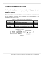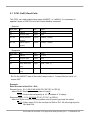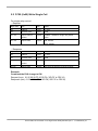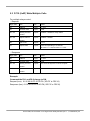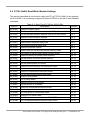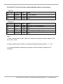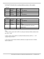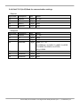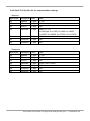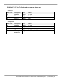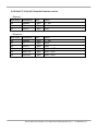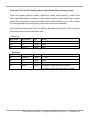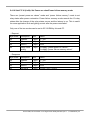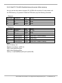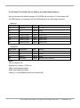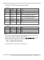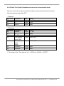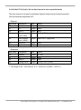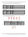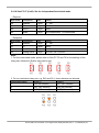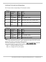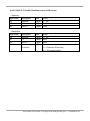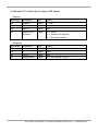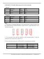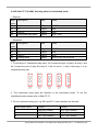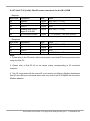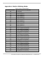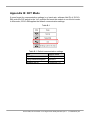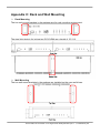
1
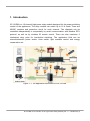
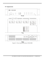
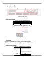
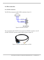
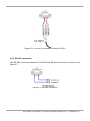
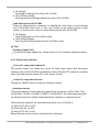
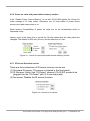
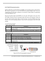
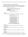
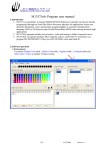
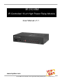
IR-310-RM IR Controlled 10-ch High Power Relay Module User Manual v1.1 www.icpdas.com IR-310-RM, IR Controlled 10-ch High Power Relay Module (Ver. 1.1, Jul/02/2013) 1 Warranty All products manufactured by ICP DAS are under warranty regarding defective materials for a period of one year from the date of delivery to the original purchaser. Warning ICP DAS assumes no liability for damages resulting from the use of this product. ICP DAS reserves the right to change this manual at any time without notice. The information furnished by ICP DAS is believed to be accurate and reliable. However, no responsibility is assumed by ICP DAS for its use, or for any infringements of patents or other rights of third parties resulting from its use. Copyright Copyright 2013 by ICP DAS. All rights are reserved. Trademark The names used for identification only may be registered trademarks of their respective companies. IR-310-RM, IR Controlled 10-ch High Power Relay Module (Ver. 1.1, Jul/02/2013) 2 Content 1. 2. INTRODUCTION ..........................................................................................................................................5 1.1 FEATURES ................................................................................................................................................... 6 1.2 APPLICATIONS .............................................................................................................................................. 6 HARDWARE ................................................................................................................................................7 2.1 SPECIFICATIONS ............................................................................................................................................ 7 2.2 APPEARANCE ............................................................................................................................................... 8 2.3 PIN ASSIGNMENTS ........................................................................................................................................ 9 2.4 WIRE CONNECTION ..................................................................................................................................... 10 2.4.1 RS-232 connection ............................................................................................................................ 10 2.4.2 RS-485 connection ............................................................................................................................ 11 2.4.3 Relay Terminal .................................................................................................................................. 12 2.4.4 IR Interface ........................................................................................................................................ 12 2.4.5 Power connection ............................................................................................................................. 12 2.5 WATCHDOG SETTING .................................................................................................................................. 13 2.6 JUMPER FOR FIRMWARE UPDATE................................................................................................................... 14 2.6.1 Update firmware mode..................................................................................................................... 14 2.6.2 Normal Operation Mode ................................................................................................................... 15 2.7 LED INDICATORS ........................................................................................................................................ 16 2.8 DIP SWITCH .............................................................................................................................................. 17 3. CONFIGURATION AND CONTROL ON IR-310-RM ...................................................................................... 19 4. CONFIGURATION UTILITY ......................................................................................................................... 20 5. 4.1 THE CONFIGURATION TOOL– IR UTILITY (WITH IR-310-RM UTILITY) ................................................................... 20 4.2 IR-310-RM UTILITY ................................................................................................................................... 21 4.2.1 Main Window of IR-310-RM Utility ................................................................................................... 21 4.2.2 Menu ................................................................................................................................................. 21 4.2.3 Relay Output Section......................................................................................................................... 23 4.2.4 Communication Settings Section ...................................................................................................... 24 4.2.5 Sequential Action for Relays Section ................................................................................................. 24 4.2.6 Power on value and power failure memory section .......................................................................... 25 4.2.7 IR Sensor Selection section ................................................................................................................ 25 4.2.8 Emit IR Commands section................................................................................................................ 26 4.2.9 Relay States Settings Corresponding to IR Cmds .............................................................................. 27 MODBUS COMMANDS FOR IR-310-RM ..................................................................................................... 29 5.1 FC01 (0X01) READ COILS ........................................................................................................................... 30 IR-310-RM, IR Controlled 10-ch High Power Relay Module (Ver. 1.1, Jul/02/2013) 3 5.2 FC05 (0X05) WRITE SINGLE COIL ................................................................................................................. 31 5.3 FC15 (0X0F) WRITE MULTIPLE COILS............................................................................................................ 32 5.4 FC100 (0X64) READ/WRITE MODULE SETTINGS............................................................................................. 33 5.4.1 Sub-FC 00 (0x00): Read module name ................................................................................................... 34 5.4.2 Sub-FC 03 (0x03): Get the software Modbus address of the module. .................................................... 35 5.4.3 Sub-FC 04 (0x04): Set the software Modbus address of the module. ..................................................... 36 5.4.4 Sub-FC 05 (0x05) Read the communication settings .............................................................................. 37 5.4.5 Sub-FC 06 (0x06): Set the communication settings ................................................................................ 38 5.4.6 Sub-FC 07 (0x07): Read module response delay time............................................................................. 39 5.4.7 Sub-FC 08 (0x08): Set module response delay time ................................................................................ 40 5.4.8 Sub-FC 32 (0x20): Read the firmware version ........................................................................................ 41 5.4.9 Sub-FC 35 (0x23): Read Power-on value/Power failure memory mode ................................................. 42 5.4.10 Sub-FC 36 (0x24): Set Power-on value/Power failure memory mode .................................................. 43 5.4.11 Sub-FC 37 (0x25): Read the latency for power failure memory ............................................................ 44 5.4.12 Sub-FC 38 (0x26): Set the latency for power failure memory ............................................................... 45 5.4.13 Sub-FC 39 (0x27): Read the preset power-on values ............................................................................ 46 5.4.14 Sub-FC 40 (0x28): Set the preset power-on values ............................................................................... 47 5.4.15 Sub-FC 64 (0x40): Read the time interval of the sequential mode ....................................................... 48 5.4.16 Sub-FC 65 (0x41): Set the time interval in the sequential mode ........................................................... 49 5.4.17 Sub-FC 66 (0x42): Read the independent/interlocked mode ................................................................ 50 5.4.18 Sub-FC 67 (0x43): Set the independent/interlocked mode ................................................................... 51 5.4.19 Sub-FC 68 (0x44): Read IR-relay-states ................................................................................................ 52 5.4.20 Sub-FC 69 (0x45): Set IR-Relay-States .................................................................................................. 53 5.4.21 Sub-FC 70 (0x46): Read the source of IR sensor ................................................................................... 54 5.4.22 Sub-FC 71 (0x47): Set the source of IR sensor....................................................................................... 55 5.4.23 Sub-FC 72 (0x48): Read Non-sequential/Sequential mode ................................................................... 56 5.4.24 Sub-FC 74 (0x4A): Read relay pairs for interlocked mode .................................................................... 57 5.4.25 Sub-FC 75 (0x4B): Set relay pairs for interlocked mode ....................................................................... 58 5.4.26 Sub-FC 76 (0x4C): Read the DIP switch state ........................................................................................ 59 5.4.27 Sub-FC 90 (0x5A): Emit IR remote commands for the IR-310-RM ........................................................ 60 5.4.28 Sub-FC 91 (0x5B) Set Forward/Backward sequential action ................................................................ 61 6. TECHNICAL SUPPORT ................................................................................................................................ 62 APPENDIX A: BUILT-IN IR-RELAY-STATES ............................................................................................................ 63 APPENDIX B: INIT MODE .................................................................................................................................... 64 APPENDIX C: RACK AND WALL MOUNTING ....................................................................................................... 65 IR-310-RM, IR Controlled 10-ch High Power Relay Module (Ver. 1.1, Jul/02/2013) 4 1. Introduction IR-310-RM is a 10-channel high power relay module designed for the power switching control of the appliances. The relay module can switch up to 10 A loads. There are NO/NC contacts and protection circuit for each channel. The channels can be controlled independently or sequentially by serial communication with Modbus RTU protocol, as well as by wireless IR remote control. There are also maximum 5 interlocked relay pairs for interlocked switching. The application field can be manual/automatic power switch, timer switch, light scenario control and energy conservation etc. Figure 1-1: The application architecture of IR-310-RM. IR-310-RM, IR Controlled 10-ch High Power Relay Module (Ver. 1.1, Jul/02/2013) 5 1.1 Features [IR-310-RM] 10 channels high power relays: 10A x 4, 5A x 6 Supports IR commands (custom:64, built-in:32) for relay control. NO and NC contacts for each channel. Protection circuit for each channel. Sequential relay control. Supports maximum 5 sets of interlocked relay pairs (e.g. CW/CCW motor control). RS-232 and RS-485 serial interface. Supports Modbus/RTU protocol. Modbus Network IDs: 1 ~ 15 (HW); 1 ~ 247 (SW). [IR Utility] IR utility is a configuration tool for the IR series modules of ICP DAS. IR-310-RM utility, as a part of the IR utility, has functions as follows: Can get/set separate or all settings from/to IR-310-RM. For relay test and relay states indication. Command IR-310-RM to emit IR signals corresponding to relay states for an IR learning remote. 1.2 Applications e-Classroom service Lighting Scenario Control Home and Building Automation IR-310-RM, IR Controlled 10-ch High Power Relay Module (Ver. 1.1, Jul/02/2013) 6 2. Hardware 2.1 Specifications Relay Output Number of Outputs Relay Types Contact Rating Operating Time(Max.) Release Time(Max.) Insulation Resistance Dielectric Strength Life TIme Serial Interface COM1 COM2 Format Baud Rate Protocol Modbus Net ID IR interface 10 Form C relay SPDT 5A@220VAC for RL0, RL1 & RL6~RL9 (Operating temperature: 25°C) 10A@220VAC for RL2 ~ RL5 (Operating temperature: 25°C) 10 ms for RL0, RL1 & RL6 ~ RL9, 15 ms for RL2 ~ RL5 5 ms for RL0, RL1 & RL6 ~ RL9 10 ms for RL2 ~ RL5 100 M Ohm min. at 500 VDC for RL0, RL1 & RL6~RL9 1000M Ohm min. at 500VDC for RL2~RL5 750VAC for RL0, RL1 & RL6~RL9 Open Contact 1000VAC for RL2 ~ RL5 1500VAC for RL0, RL1 & RL6~RL9 Contact & Coil 2500VAC for RL2 ~ RL5 Mechanical : 1 × 10^7 OPS Electrical : 1 × 10^5 OPS RS-232 (TxD, RxD, GND) RS-485 (DATA+, DATA-) Parity: None, Databits: 8, Stopbits: 1 9600 ~ 115200 bps Modbus/RTU (Slave) Hardware: 1 ~ 15; Software: 1 ~ 247 IR input IR Remote Commands Onboard IR receiver 3.5 mm audio jack for an IR receiver cable 64 IR commands (#0~#63) corresponding to self-defined relay states. 32 IR commands (#192~#223) corresponding to built-in relay states. LED Display 1 LED as power indication 10 LEDs as relay output indicators Power Po we r Con su mp t ion 6. 5 W ( ma x) Environment Operating Temperature -25 to +75°C Storage Temperature -30 to 80°C Humidity 10 to 90%, non-condensing Mechanism Dimensions(W x H x D) 220 mm x 48 mm x 113 mm IR-310-RM, IR Controlled 10-ch High Power Relay Module (Ver. 1.1, Jul/02/2013) 7 2.2 Appearance Front Top Rear Figure 2-1: Front, top and rear view of IR-310-RM. IR-310-RM, IR Controlled 10-ch High Power Relay Module (Ver. 1.1, Jul/02/2013) 8 2.3 Pin assignments Figure 2-2: Rear view 1. Relay output terminal Table 2-1: Pin assignments of relays Pin of Relay NO# NC# COM# Description Normally Open Normally Closed Common where # is the relay number (# = 0 ~ 9) Figure 2-2 2. IR interface IR Input: 3.5 mm audio jack for the IR receiver cable CA-IR-001. IR Output: 3.5 mm audio jack for the IR emitter cable CA-IR-SH2251-5. 3. Communication terminal Table 2-2: Pin assignments of serial port Serial port Pin DATA+ RS-485 GND DATATxD RS-232 RxD GND IR-310-RM, IR Controlled 10-ch High Power Relay Module (Ver. 1.1, Jul/02/2013) 9 2.4 Wire connection 2.4.1 RS-232 connection The RS-232 pin assignment of IR-310-RM is depicted as figure 2-4. Figure 2-4: RS-232 connection The accompanied cable CA-0910 can be used for the RS-232 connection to the IR310-RM. The RS-232 connection using CA-0910 is shown in Figure 2-6. Figure 2-5: RS-232 connection cable (CA-0910) IR-310-RM, IR Controlled 10-ch High Power Relay Module (Ver. 1.1, Jul/02/2013) 10 Figure 2-6: The RS-232 connection using CA-0910 2.4.2 RS-485 connection The RS-485 connection between IR-310-RM and RS-485 host device is shown in the figure 2-7. Figure 2-7: RS-485 connection IR-310-RM, IR Controlled 10-ch High Power Relay Module (Ver. 1.1, Jul/02/2013) 11 2.4.3 Relay Terminal Figure 2-8: Wire connection for relay output 2.4.4 IR Interface Please use IR receiver cable CA-IR-001 for IR input jack and IR emitter cable CA-IRSH2251-5 for IR output jack. Figure 2-9. 2.4.5 Power connection The IR-310-RM only supports +12 VDC. FRA05-S12-SU is a recommended power supply with a DC connector which supplys 12 VDC/max.0.58A. Figure 2-10: DC power jack for +12 VDC IR-310-RM, IR Controlled 10-ch High Power Relay Module (Ver. 1.1, Jul/02/2013) 12 2.5 Watchdog Setting The watchdog is a timer to reset the hung system due to some fault conditions. The watchdog of the IR-310-RM can be enabled or disabled by JP1 as shown in Figure 211. It is necessary to open the case to set JP1. The watchdog is enabled by default. Figure 2-11: JP1setting for Hardware WDT IR-310-RM, IR Controlled 10-ch High Power Relay Module (Ver. 1.1, Jul/02/2013) 13 2.6 Jumper for Firmware Update There is a jumper JP5 in the case of IR-310-RM for setting the operation mode (OP) or Firmware update mode (FW). Figure 2-12: JP5 setting for Firmware Update 2.6.1 Update firmware mode Set the JP5 to “FW” position and power cycle the IR-310-RM to enable the firmware update mode. At the same time the power LED blinks rapidly 4 times per second. In the FW mode, you have to use RS-232 port to update firmware by the Firmware Update Tool. Please click the menu of IR-310-RM utility [Tool] -> [Firmware Update Tool] to launch the firmware update tool. According to the following steps, you can finish the update firmware procedures in the Fig. 2-13. (1) Select “COM” and “COM Port” (2) Click “Browser” to select the firmware file (ir310rm_v#_#_#.fw). (3) Click “Firmware Update” to start the update procedure. 1 2 3 Fig. 2-13: Update firmware Tool for IR-310-RM IR-310-RM, IR Controlled 10-ch High Power Relay Module (Ver. 1.1, Jul/02/2013) 14 Note: 1. Use RS-232 port to update firmware. 2. After updating firmware, remember to change the JP5 to the “OP” position and power cycle the IR-310-RM to run in the operation mode. The firmware of IR-310-RM can be downloaded from: ftp://ftp.icpdas.com/pub/cd/usbcd/napdos/ir-310-rm/firmware/ Firmware_Update_Tool can be downloaded from: ftp://ftp.icpdas.com/pub/cd/usbcd/napdos/ir-310-rm/software/fw_update_tool/ 2.6.2 Normal Operation Mode Set the JP5 to the “OP” in figure 2-11 and power cycle the IR-310-RM to enable the Normal Operation Mode. IR-310-RM, IR Controlled 10-ch High Power Relay Module (Ver. 1.1, Jul/02/2013) 15 2.7 LED Indicators There are two kinds of LEDs for IR-310-RM to indicate several states. (1) Power LED : The PWR LED is ON to indicate the IR-310-RM is turned on. Figure 2-14: Power LED (2) Relay State LEDs These 10 LEDs indicate the states of the 10 relays(RL) where: Table 2-3 Relay LED and Contact Position Relay State Contact Position RL# ON Normally Open RL# OFF Normally Closed Figure 2-15: Relay States LEDs (3) List of LED State Table 2-4: The State List of LEDs for IR-310-RM LED State Comments PWR ON Power ON / Normal operation mode PWR OFF Power OFF PWR Blinking 4 times/s Firmware update mode PWR Blink 2 times/sec Receiving an IR command PWR Blink 1 time Emitting an IR command by the utility RL0 ~ RL9 ON Contact in Normally Open RL0 ~ RL9 ON Contact in Normally Closed IR-310-RM, IR Controlled 10-ch High Power Relay Module (Ver. 1.1, Jul/02/2013) 16 2.8 DIP Switch There four states of the 2-pin dip switch which represent four modes for IR-310-RM as shown in table 2-5. To take effect the setting, please power cycle the module after set the dip switch. Table 2-5: Four states of dip switch. (1) Normal Mode The mode except other three modes. (2) Sequential mode In this mode, the 10 relay can be switch forward to NO or backward to NC sequentially. (3) Init mode In this initialization mode, IR-310-RM always use the default communication settings. Table 2-5 Default communication settings Item Default value Baud Rate 9600 bps Parity/Databits/Stopbtis None/8/1 Modbus Net ID 1 (4) Emitting built-in IR commands mode (corresponding to built-in IR-Relay-States) Built-in IR commands are the IR commands corresponding to the built-in 10 relay states (Refer to appendix A). In this mode, IR-310-RM will emit IR commands #192 ~ #203 sequentially from the IR output channel. The flowchart of this process is depicted in figure 2-16. Users can set the IR learning remote control in the learning mode to learn these IR commands for test as shown in figure 2-17. IR-310-RM, IR Controlled 10-ch High Power Relay Module (Ver. 1.1, Jul/02/2013) 17 Figure 2-16: The flowchart of emitting built-in IR commands Figure 2-17: Use IR learning remote to learn IR commands. IR-310-RM, IR Controlled 10-ch High Power Relay Module (Ver. 1.1, Jul/02/2013) 18 3. Configuration and Control on IR-310-RM There are two ways to configure and control IR-310-RM. One is the easy IR-310-RM utility for test and settings and the other is the Modbus/RTU commands for the Modbus master. Please refer to chapter 4 and 5 to learn the IR-310-RM utility and the Modbus commands. IR-310-RM, IR Controlled 10-ch High Power Relay Module (Ver. 1.1, Jul/02/2013) 19 4.Configuration Utility 4.1 The configuration tool– IR Utility (with IR-310-RM Utility) The IR Utility is the integration utility for configuration of IR series modules. It needs the environment of the .NET Framework 4 client profile based on Microsoft Windows. Users can download the IR Utility from: ftp://ftp.icpdas.com/pub/cd/usbcd/napdos/ir-310-rm/software/Utility/ If the environment of .NET Framework 4 client profile is not available on the Microsoft OS, please download and install the redistributable packages as follows: Web Installer http://www.microsoft.com/download/en/details.aspx?id=17113 Standalone Installer http://www.microsoft.com/download/en/details.aspx?id=24872 IR-310-RM Utility is a part of the IR Utility. Please select the “IR-310-RM” item in the Module combobox and click the “Connect/Open Interface” button to get the IR-310-RM utility. Figure 4-1: The main window of IR Utility with the IR-310-RM selected. The default communication settings of IR-310-RM are listed in table 4-1. Table 4-1 Default communication settings Item Default value Baud Rate 9600 bps Parity/Databits/Stopbtis None/8/1 Modbus Net ID 1 IR-310-RM, IR Controlled 10-ch High Power Relay Module (Ver. 1.1, Jul/02/2013) 20 4.2 IR-310-RM Utility 4.2.1 Main Window of IR-310-RM Utility IR-310-RM Utility is a part of the IR Utility. IR-310-RM Utility gives an easy interface to configure IR-310-RM. Users can also refer to chapter 5 for the control and settings on IR-310-RM by the Modbus commands. Figure 4-2: The main window of IR-310-RM Utility connecting to an IR-310-RM. 4.2.2 Menu Table 4-2 explains the menu of the IR-310-RM Utility. Table 4-2: Items of the menu Item File Sub item Description Save Settings to File Save all settings to a file (for IR-310-RM). Load Settings from File Load all settings from a file (for IR-310-RM). IR-310-RM, IR Controlled 10-ch High Power Relay Module (Ver. 1.1, Jul/02/2013) 21 Close IR-310-RM Utility Close IR-310-RM Utility. Connect IR-310-RM Connection of serial port to IR-310-RM. Disconnect IR-310-RM Disconnection of serial port from IR-310-RM. Download Settings to IR-310-RM Download settings from utility to IR-310-RM. Load Settings from IR-310-RM Get settings from IR-310-RM to utility. Tool Firmware Update Tool Tool for updating firmware. About About IR-310-RM Utility Show version of the IR-310-RM utility. Connect Settings (1) File ‧Save Settings to File Save all settings buffered in the IR-310-RM utility to a file with the filename extension “.ird”. ‧Load Settings from File Load all settings from the ird file of IR-310-RM and put them in the IR-310-RM utility. ‧Close IR-310-RM Utility Close IR-310-RM utility and back to the main window of IR utility. (2) Connect ‧Connect IR-310-RM Open the dialog to connect IR-310-RM. Please refer to table 4-1 for default communication settings. After connection is established, the current states of the 10 relays are always displayed in the utility. Figure 4-3: Dialog of connecting IR-310-RM. ‧Disconnect IR-310-RM Disconnect the connection between the utility and IR-310-RM. (3) Setting ‧Download Settings to IR-310-RM IR-310-RM, IR Controlled 10-ch High Power Relay Module (Ver. 1.1, Jul/02/2013) 22 a. All Settings: Download all settings from utility to IR-310-RM. b. Only IR-Relay-States: Only download the IR-Relay-States from utility to IR-310-RM. ‧Load Settings from IR-310-RM When the communication connection is established, utility does not load settings from IR-310-RM. Users have to click “get” buttons to get setting values in each section or click this menu item to load all setting values from IR-310-RM. a. All Settings: Load all settings from IR-310-RM to utility. b. Only IR-Relay-States: Only load the IR-Relay-States from IR-310-RM to utility. (4) Tool ‧Firmware Update Tool Launch the firmware update tool. Please refer to 2.6 for firmware update procedure. “” 4.2.3 Relay Output Section ‧ Current 10 relay states indication This section (figure 3-8) shows the current 10 relay output states after connection between utility and IR-310-RM is established. Relay ON and OFF means the normally open (NO) and normally closed (NC) of the relay’s contact. ‧ Control 10 relay states for test Change the ON/OFF state of relays by clicking the circles. ‧Interlocked mode There are maximum 5 interlocked relay pairs which can be set on IR-310-RM. They are RL0/RL1, RL2/RL3, RL4/RL5, RL6/RL7, and RL8/RL9. The interlocked relay pairs are effective when the “Enable Interlocked Mode” checkbox is checked and set. There are three states for an interlocked relay pairs (e.g. for RL0/RL1): (1) RL0 is OFF; RL1 is OFF. (2) RL0 is ON; RL1 is OFF. (3) RL0 is OFF; RL1 is ON. Being ON state of both relays is not allowed in a relay pair. IR-310-RM, IR Controlled 10-ch High Power Relay Module (Ver. 1.1, Jul/02/2013) 23 Figure 4-4: Relay output section 4.2.4 Communication Settings Section This section can set the software Modbus Net ID and baud rate of the COM port. Please reset the module to make the change effective. The “Curr. ID” and “Curr. Baud” represent the current Modbus Net ID and current baud rate of the IR-310-RM. Figure 4-5: Communication settings section 4.2.5 Sequential Action for Relays Section To enable/disable the sequential mode, please refer to previous section 2.8 to adjust the DIP switch. This section shows current state of the sequential mode and time interval (ms) for sequential action of relays after clicking the get buttons. The range of the time interval is 0 to 65535 ms. Figure 4-6: Settings of sequential relay action. IR-310-RM, IR Controlled 10-ch High Power Relay Module (Ver. 1.1, Jul/02/2013) 24 4.2.6 Power on value and power failure memory section If the “Enable Power Failure Memory” is not set, IR-310-RM applies the Power On Value settings of 10 relay states. Otherwise, the 10 relay states of power failure memory are used when power is on. Radio buttons Forward/Stop of power on value are for the forward/stop action in sequential mode. Latency (sec) is the delay time to record the 10 relay states after the relay states are changed. The default is 1800 sec (30 min) and the minimum is 5 sec. Figure 4-7: Power on value and power failure memory section. 4.2.7 IR Sensor Selection section There are three selections of IR sensor sources can be set. (1) On-board IR sensor: The sensor is located in the front panel. (2) IR Receiver Cable: Use “IR Output” channel. CA-IR-001 needs to be plugged into the “IR Output” jack (3.5 mm audio jack). (3) No sensor: Disable the IR remote function. Figure 4-8: Source of IR sensor. IR-310-RM, IR Controlled 10-ch High Power Relay Module (Ver. 1.1, Jul/02/2013) 25 4.2.8 Emit IR Commands section Custom and built-in IR commands are available for IR remote control on the IR-310RM. Each IR command is for an IR-310-RM with specific Modbus Net ID and the corresponding IR-relay-state configured in the section of Relay States Corresponding to IR cmds (Section 4.2.9). Plug the IR emitter cable CA-IR-SH2251-5 in the jack of IR Output at the rear of the IR-310-RM. Click the “Emit IR Command” button will emit an IR command. Users can aim the head of the IR emitter cable to the IR receiver of the IR-310-RM for test. This function is for the IR learning remote to learn the IR commands for the IR-310-RM module. (1) Custom IR commands ‧Nons equential mode IR cmd # 0 ~ 63 Description The IR commands corresponding to customizable 10 relays states. (Refer to 4.2.9) 192 ~ 223 32 IR commands corresponding to the built-in relay states. (Appendix A) ‧Sequential mode IR cmd # Description 0 Stop the forward/backward sequential action. 1 Have 10 relays move forward to NO sequentially. 2 Have10 relays move backward to NC sequentially. 3 ~ 63 IR commands corresponding to customizable 10 relays states. (Refer to 4.2.9) 192 ~ 223 IR commands corresponding to the built-in relay states. (Appendix A) Figure 4-9: Emit IR commands for learning.. IR-310-RM, IR Controlled 10-ch High Power Relay Module (Ver. 1.1, Jul/02/2013) 26 4.2.9 Relay States Settings Corresponding to IR Cmds IR-relay-state can be buffered in each item (#=0~63) of the “IR Cmd No.” combobox by clicking the circles representing the 10 relays RL0 ~ RL9. Click a circle ON means the relay ON (Normally open). The circle OFF means the relay OFF (Normally closed). Figure 4-10: Source of IR sensor. ‧ List button List all IR-relay-states of IR command# 0 ~ 63 buffered in the utility by a sheet. Figure 4-11: List of IR-relay-states in the utility. ‧ Clear button Change 10 relay states to OFF state for the item of the IR cmd No combobox. ‧ Clear All button Change 10 relay states to OFF state for all the items (0 ~ 63) of the IR cmd No combobox.. ‧ Set button Set the IR-relay-state for the item of the IR cmd No combobox to the connected IR310-RM. ‧ Get button Get the IR-relay-state for the item of the IR cmd No combobox from the connected IR-310-RM. IR-310-RM, IR Controlled 10-ch High Power Relay Module (Ver. 1.1, Jul/02/2013) 27 ‧ Set All button Equivalent to Menu [Settings] => [Download Settings to IR-310-RM]=>[Only IRRelay-States]. ‧ Get All button Equivalent to Menu [Settings] => [Load Settings from IR-310-RM]=>[Only IR-RelayStates]. IR-310-RM, IR Controlled 10-ch High Power Relay Module (Ver. 1.1, Jul/02/2013) 28 5. Modbus Commands for IR-310-RM The following Function Code commands are provided for a Modbus master to control and configure IR-310-RM. It is necessary to append 2 bytes of CRC16 to the tail of each Modbus command. FC01, 05, and 15 are the standard Modbus commands for Modbus masters to access the relay outputs of IR-310-RM. Sub-FC commands of FC100 are specific to the settings and control on IR-310-RM. Table 5-1: Modbus Function Calls for IR-310-RM Function Code Description Section 01 (0x01) Read coils (relay output states) 5.1 05 (0x05) Write single coil (single relay output) 5.2 15 (0x0F) Write multiple coils (multiple relay outputs) 5.3 100 (0x64) Commands for the settings of the IR-310-RM. 5.4 Figure 5-1 IR-310-RM, IR Controlled 10-ch High Power Relay Module (Ver. 1.1, Jul/02/2013) 29 5.1 FC01 (0x01) Read Coils This FC01 can read multiple relay states (ON/OFF, i.e. NO/NC). It is necessary to append 2 bytes of CRC16 to the tail of each Modbus command. ‧Request Byte order Item Size Value 00 Address 1 Byte 1 ~ 247 01 Function code 1 Byte 0x01 02 ~ 03 Starting channel 2 Bytes 0x0000 ~ 0x000A 2 Bytes 0x0000 ~ 0x000A numbers 04 ~ 05 Output channel quantity ‧Response Byte order Item Size Value 00 Address 1 Byte 1 ~ 247 01 Function code 1 Byte 0x01 02 Byte count 1 Bytes 1 or 2 03 Relay status (low 1 Byte 0x00 ~ 0xFF. (*) 1 Byte 0x00 ~ 0x03. (*) byte) 04 Relay status (high byte) * It depends on start channel number and output channel quantity. Bit 0 is the ON/OFF state of the relay 0 where value = 1 means ON and value = 0 means OFF. Example: Read the state of the RL0 ~ RL9. Request (hex): 01 01 00 00 00 0A BC 0D (“BC 0D” is CRC16) where 00 00: Starting channel number is relay 0. 00 0A: Output channel quantity is 10. Get states of 10 relays. Response (hex): 01 01 02 D5 00 E7 6C (“E7 6C” is CRC16) where 02: Byte count is 2. 10 relay states need 2 bytes to get back the states. D5 00: Relay status. D5 is the low byte for RL0 to RL7. 00 is the high byte for RL8 and RL9. IR-310-RM, IR Controlled 10-ch High Power Relay Module (Ver. 1.1, Jul/02/2013) 30 5.2 FC05 (0x05) Write Single Coil For single relay control. ‧Request Byte order Item Size Value 00 Address 1 Byte 1 ~ 247 01 Function code 1 Byte 0x05 02 ~ 03 Output channel 2 Bytes 0x0000 ~ 0x0009 for single relay status number 04 ~ 05 Output value value. 2 Bytes ON: 0xFF00 OFF: 0x0000 ‧Response Byte order Item Size Value 00 Address 1 Byte 1 ~ 247 01 Function code 1 Byte 0x05 02 ~ 03 Output channel 2 Bytes The same as byte 02~03 of the request. 2 Bytes The same as byte 04~05 of the request. number 04~05 Output value Example: Command the RL8 change to ON. Request (hex): 01 05 00 08 FF 00 0D F8 (“0D F8” is CRC16) Response (hex): 01 05 00 08 FF 00 0D F8 (“0D F8” is CRC16) IR-310-RM, IR Controlled 10-ch High Power Relay Module (Ver. 1.1, Jul/02/2013) 31 5.3 FC15 (0x0F) Write Multiple Coils For multiple relays control. ‧Request Byte order Item Size Value 00 Address 1 Byte 1 ~ 247 01 Function code 1 Byte 0x0F 02 ~ 03 Starting channel 2 Bytes 0x0000 ~ 0x0009 for relay status. 2 Bytes 0x0000 ~ 0x000A number 04 ~ 05 Output channel number 06 Byte count 1 Bytes 1 or 2 07 Output value 1 Bytes A bit corresponding to a channel. Bit value 1 => ON; Bit value 0 => OFF. ‧Response Byte order Item Size Value 00 Address 1 Byte 1 ~ 247 01 Function code 1 Byte 0x0F 02 ~ 03 Starting channel 2 Bytes The same as byte 02~03 of the request. 2 Bytes The same as byte 04~05 of the request. number 04~05 Input channel number Example: Command the RL1 and RL8 change to ON. Request (hex): 01 05 00 08 FF 00 0D F8 (“0D F8” is CRC16) Response (hex): 01 05 00 08 FF 00 0D F8 (“0D F8” is CRC16) IR-310-RM, IR Controlled 10-ch High Power Relay Module (Ver. 1.1, Jul/02/2013) 32 5.4 FC100 (0x64) Read/Write Module Settings This section describes all sub function calls (sub-FC) of FC100 (0x64) for the settings on IR-310-RM. It is necessary to append 2 bytes of CRC16 to the tail of each Modbus command. Table 5-2: Sub-FCs of FC100 for IR-310-RM Sub-FC Description Section 00 (0x00) Read the module name. 5.4.1 03 (0x04) Read the software Modbus address (Net ID) of the module. 5.4.2 04 (0x04) Set the software Modbus address (Net ID) of the module. 5.4.3 05 (0x05) Read the communication settings. 5.4.4 06 (0x06) Set the communication settings. 5.4.5 07 (0x07) Read module response delay time. 5.4.6 08 (0x08) Set module response delay time. 5.4.7 32 (0x20) Read the firmware version. 5.4.8 35 (0x23) Read Power-on value/Power failure memory mode. 5.4.9 36 (0x24) Set Power-on value/Power failure memory mode. 5.4.10 37 (0x25) Read the latency for power failure memory. 5.4.11 38 (0x26) Set the latency for power failure memory. 5.4.12 39 (0x27) Read the preset power-on values. 5.4.13 40 (0x28) Set the preset power-on values. 5.4.14 64 (0x40) Read the time interval of the sequential mode. 5.4.15 65 (0x41) Set the time interval of the sequential mode. 5.4.16 66 (0x42) Read the independent/interlocked mode. 5.4.17 67 (0x43) Set the independent/interlocked mode. 5.4.18 68 (0x44) Read IR-relay-states. 5.4.19 69 (0x45) Set IR-relay-states. 5.4.20 70 (0x46) Read the source of IR sensor. 5.4.21 71 (0x47) Set the source of IR sensor. 5.4.22 72 (0x48) Read Non-sequential/Sequential mode. 5.4.23 74 (0x4A) Read relay pairs for interlocked mode. 5.4.24 75 (0x4B) Set relay pairs for interlocked mode. 5.4.25 76 (0x4C) Read the DIP switch state 5.4.26 90 (0x5A) Emit IR remote commands for the IR-310-RM. 5.4.27 91 (0x5B) Set Forward/Backward sequential relay action. 5.4.28 IR-310-RM, IR Controlled 10-ch High Power Relay Module (Ver. 1.1, Jul/02/2013) 33 5.4.1 Sub-FC 00 (0x00): Read module name ‧Request Byte order Description Size Value 00 Address 1 Byte 1 ~ 247 01 FC 1 Byte 0x64 02 Sub-FC 1 Byte 0x00 ‧Response Byte order Description Size Value 00 Address 1 Byte 1 ~ 247 01 FC 1 Byte 0x64 02 Sub-FC 1 Byte 0x00 12 Bytes Hex ASCII code of characters. 0x00 is none. “IR310RM”=> 0x49,0x52,0x33,0x31,0x30,0x52,0x4D 03~14 Module name IR-310-RM, IR Controlled 10-ch High Power Relay Module (Ver. 1.1, Jul/02/2013) 34 5.4.2 Sub-FC 03 (0x03): Get the software Modbus address of the module. ‧Request Byte order Description Size Value 00 Address 1 Byte 1 ~ 247 (Net ID) 01 FC 1 Byte 0x64 02 Sub-FC 1 Byte 0x03 ‧Response Byte order Description Size Value 00 Address 1 Byte 0x0 ~ 0xF7 (1 ~ 247) (Net ID) 01 FC 1 Byte 0x64 02 Sub-FC 1 Byte 0x03 03 SW Net ID 1 Byte 0x0 ~ 0xF7 (1 ~ 247) (Net ID) 04 Reserved 1 Byte 0x00 Note: 1. Rotary switch position 0x01~0x0F is for setting the hardware Modbus address (Net ID) = 0x01 ~ 0x0F. 2. Rotary switch position 0x00 is for software Modbus address (Net ID) = 1 ~ 247. 3. If hardware Modbus addresses are applied, software Modbus addresses are ineffective. IR-310-RM, IR Controlled 10-ch High Power Relay Module (Ver. 1.1, Jul/02/2013) 35 5.4.3 Sub-FC 04 (0x04): Set the software Modbus address of the module. ‧Request Byte order Description Size Value 00 Address 1 Byte 1 ~ 247 (Net ID) 01 FC 1 Byte 0x64 02 Sub-FC 1 Byte 0x04 03 New addr. 1 Byte 1 ~ 247(Net ID) 04 reserved 1 Byte 0x00 Byte order Description Size Value 00 Address 1 Byte 1 ~ 247 (Net ID) 01 FC 1 Byte 0x64 02 Sub-FC 1 Byte 0x04 03 Set result 1 Byte 0=>OK; 1=>OK, but HW Net ID is used now; others=>error. 04 Reserved 1 Byte 0x00 ‧Response Note: 1. Rotary switch position 0x01~0x0F is for setting the hardware Modbus address (Net ID) = 0x01 ~ 0x0F. 2. Rotary switch position 0x00 is for software Modbus address (Net ID) = 1 ~ 247 configured by this Sub-FC. 3. The priority of the hardware Modbus addresses are higher than that of software Modbus addresses. IR-310-RM, IR Controlled 10-ch High Power Relay Module (Ver. 1.1, Jul/02/2013) 36 5.4.4 Sub-FC 05 (0x05) Read the communication settings ‧Request Byte order Description Size Value 00 Address 1 Byte 1 ~ 247 01 FC 1 Byte 0x64 02 Sub-FC 1 Byte 0x05 03 reserved 1 Byte 0x00 Byte order Description Size Value 00 Address 1 Byte 1 ~ 247 01 FC 1 Byte 0x64 02 Sub-FC 1 Byte 0x05 03 Baud rate 1 Byte Index = 3 ~ 10 3=>1200 bps, 4=>2400, 5=>4800, 6=>9600, 7=>19200, 8=>38400, 9=>57600, 10=>115200 04 Reserved 1 Byte 0x00 05 Reserved 1 Byte 0x00 06 Reserved 1 Byte 0x00 ‧Response IR-310-RM, IR Controlled 10-ch High Power Relay Module (Ver. 1.1, Jul/02/2013) 37 5.4.5 Sub-FC 06 (0x06): Set the communication settings ‧Request Byte order Description Size Value 00 Address 1 Byte 1 ~ 247 01 FC 1 Byte 0x64 02 Sub-FC 1 Byte 0x06 03 Baud rate 1 Byte Index = 3 ~ 10 3=>1200 bps, 4=>2400, 5=>4800, 6=>9600, 7=>19200, 8=>38400, 9=>57600, 10=>115200 04 Reserved 1 Byte 0x00 05 Reserved 1 Byte 0x00 06 Reserved 1 Byte 0x00 ‧Response Byte order Description Size Value 00 Address 1 Byte 1 ~ 247 01 FC 1 Byte 0x64 02 Sub-FC 1 Byte 0x06 03 Baud rate 1 Byte 0=>OK, 0xFF=>error 04 Reserved 1 Byte 0x00 05 Reserved 1 Byte 0x00 06 Reserved 1 Byte 0x00 IR-310-RM, IR Controlled 10-ch High Power Relay Module (Ver. 1.1, Jul/02/2013) 38 5.4.6 Sub-FC 07 (0x07): Read module response delay time ‧Request Byte order Description Size Value 00 Address 1 Byte 1 ~ 247 01 FC 1 Byte 0x64 02 Sub-FC 1 Byte 0x07 Byte order Description Size Value 00 Address 1 Byte 1 ~ 247 01 FC 1 Byte 0x64 02 Sub-FC 1 Byte 0x07 03 MB resp. 1 Byte 0 ~ 60 ms, default: 1ms ‧Response delay time IR-310-RM, IR Controlled 10-ch High Power Relay Module (Ver. 1.1, Jul/02/2013) 39 5.4.7 Sub-FC 08 (0x08): Set module response delay time ‧Request Byte order Description Size Value 00 Address 1 Byte 1 ~ 247 01 FC 1 Byte 0x64 02 Sub-FC 1 Byte 0x08 03 MB resp. delay time 1 Byte 0x00~0x3C(0 ~ 60 ms), default: 1ms Byte order Description Size Value 00 Address 1 Byte 1 ~ 247 01 FC 1 Byte 0x64 02 Sub-FC 1 Byte 0x08 03 MB resp. delay time 1 Byte 0=>OK, 0xFF=>error ‧Response IR-310-RM, IR Controlled 10-ch High Power Relay Module (Ver. 1.1, Jul/02/2013) 40 5.4.8 Sub-FC 32 (0x20): Read the firmware version ‧Request Byte order Description Size Value 00 Address 1 Byte 1 ~ 247 01 FC 1 Byte 0x64 02 Sub-FC 1 Byte 0x20 Byte order Description Size Value 00 Address 1 Byte 1 ~ 247 01 FC 1 Byte 0x64 02 Sub-FC 1 Byte 0x20 03 Major Ver. 1 Byte 0x00 ~ 0xFF 04 Minor Ver. 1 Byte 0x00 ~ 0xFF 05 Build Ver. 1 Byte 0x00 ~ 0xFF ‧Response IR-310-RM, IR Controlled 10-ch High Power Relay Module (Ver. 1.1, Jul/02/2013) 41 5.4.9 Sub-FC 35 (0x23): Read Power-on value/Power failure memory mode There are “preset power-on values” mode and “power failure memory” mode to set relay states after power restoration. Power failure memory mode records the 10 relay states after the change of the relay states occurs and the latency is up. This is useful for some application such as lighting control after the power restoration. One of the two modes used by IR-310-RM can be read by this sub-FC. Only one of the two modes can be used at the same time. ‧Request Byte order Description Size Value 00 Address 1 Byte 1 ~ 247 01 FC 1 Byte 0x64 02 Sub-FC 1 Byte 0x23 Byte order Description Size Value 00 Address 1 Byte 1 ~ 247 01 FC 1 Byte 0x64 02 Sub-FC 1 Byte 0x23 03 Mode 1 Byte 0=>Apply “preset power-on values”. 1=>Apply “power failure memory values”. ‧Response IR-310-RM, IR Controlled 10-ch High Power Relay Module (Ver. 1.1, Jul/02/2013) 42 5.4.10 Sub-FC 36 (0x24): Set Power-on value/Power failure memory mode There are “preset power-on values” mode and “power failure memory” mode to set relay states after power restoration. Power failure memory mode records the 10 relay states after the change of the relay states occurs and the latency is up. This is useful for some application such as lighting control after the power restoration. Only one of the two modes can be set to IR-310-RM by this sub-FC. ‧Request Byte order Description Size Value 00 Address 1 Byte 1 ~ 247 01 FC 1 Byte 0x64 02 Sub-FC 1 Byte 0x24 03 Relay value setting 1 Byte 0=>Apply “preset power-on values”. 1=>Apply “power failure memory values”. Byte order Description Size Value 00 Address 1 Byte 1 ~ 247 01 FC 1 Byte 0x64 02 Sub-FC 1 Byte 0x24 03 Set result 1 Byte 0=>OK, 0xFF=>Error. ‧Response IR-310-RM, IR Controlled 10-ch High Power Relay Module (Ver. 1.1, Jul/02/2013) 43 5.4.11 Sub-FC 37 (0x25): Read the latency for power failure memory As soon as the relay states changed, IR-310-RM will record the 10 relay states until the PFM latency (ms) passed. Read the PFM latency by the following command. ‧Request Byte order Description Size Value 00 Address 1 Byte 1 ~ 247 01 FC 1 Byte 0x64 02 Sub-FC 1 Byte 0x25 Byte order Description Size Value 00 Address 1 Byte 1 ~ 247 01 FC 1 Byte 0x64 02 Sub-FC 1 Byte 0x25 03 Latency byte0 1 Byte 0x00~0xFF. LSB of Latency. 04 Latency byte1 1 Byte 0x00~0xFF 05 Latency byte2 1 Byte 0x00~0xFF 06 Latency byte3 1 Byte 0x00~0xFF. MSB of Latency. ‧Response Note: Unit of Latency: ms Minimum of Latency = 5000 ms LSB: Least Significant Byte MSB: Most Significant Byte Latency => byte3(MSB) byte2 byte1 byte0(LSB) IR-310-RM, IR Controlled 10-ch High Power Relay Module (Ver. 1.1, Jul/02/2013) 44 5.4.12 Sub-FC 38 (0x26): Set the latency for power failure memory As soon as the relay states changed, IR-310-RM will record the 10 relay states until the PFM latency (ms) passed. Set the PFM latency by the following command. ‧Request Byte order Description Size Value 00 Address 1 Byte 1 ~ 247 01 FC 1 Byte 0x64 02 Sub-FC 1 Byte 0x26 03 Latency byte0 1 Byte 0x00~0xFF 04 Latency byte1 1 Byte 0x00~0xFF 05 Latency byte2 1 Byte 0x00~0xFF 06 Latency byte3 1 Byte 0x00~0xFF Byte order Description Size Value 00 Address 1 Byte 1 ~ 247 01 FC 1 Byte 0x64 02 Sub-FC 1 Byte 0x26 03 Set result 1 Byte 0=>OK, 0xFF=>Error ‧Response Note: Unit of Latency: ms Minimum of Latency = 5000 ms LSB: Least Significant Byte MSB: Most Significant Byte Latency => byte3(MSB) byte2 byte1 byte0(LSB) IR-310-RM, IR Controlled 10-ch High Power Relay Module (Ver. 1.1, Jul/02/2013) 45 5.4.13 Sub-FC 39 (0x27): Read the preset power-on values ‧Request Byte order Description Size Value 00 Address 1 Byte 1 ~ 247 01 FC 1 Byte 0x64 02 Sub-FC 1 Byte 0x27 Byte order Description Size Value 00 Address 1 Byte 1 ~ 247 01 FC 1 Byte 0x64 02 Sub-FC 1 Byte 0x27 03 Power-on 1 Byte 0x00~0xFF. Bit 0 ~ bit 7 => RL0 ~ RL7 ‧Response value byte0 Bit# = 1 / 0 means RL# ON / OFF. 04 Power-on value byte1 1 Byte 0x00~0x03. Bit 0 & bit 1 => RL8 & RL9 Bit# = 1 / 0 means RL# ON / OFF. 05 Reserved 1 Byte 0x00 06 Reserved 1 Byte 0x00 07 Sequential action 1 Byte 0=>stop, 1=>forward Note: 1. For “Power-on value byte0 and byte1”, byte0 represents the state of RL0~RL7 and the least two bits of byte 1 are the state of RL8 and RL9. The binary representation of the byte1 and byte 0 is 0000 00## #### #### where the least significant bit# (the rightest) is RL0 and the most significant bit# is RL9. Bit# = 1 => Relay# is ON (at NO contact) Bit# = 0 => Relay# is OFF (at NC contact) 2. Sequential action” is only effective in sequential mode. IR-310-RM, IR Controlled 10-ch High Power Relay Module (Ver. 1.1, Jul/02/2013) 46 5.4.14 Sub-FC 40 (0x28): Set the preset power-on values ‧Request Byte order Description Size Value 00 Address 1 Byte 1 ~ 247 01 FC 1 Byte 0x64 02 Sub-FC 1 Byte 0x28 03 Power-on value byte0 1 Byte 0x00~0xFF. Bit 0 ~ bit 7 => RL0 ~ RL7 Bit# = 1 / 0 means RL# ON / OFF. 04 Power-on value byte1 1 Byte 0x00~0x03. Bit 0 & bit 1 => RL8 & RL9 Bit# = 1 / 0 means RL# ON / OFF. 05 Reserved 1 Byte 0x00 06 Reserved 1 Byte 0x00 07 Sequential 1 Byte 0=>stop, 1=>forward action ‧Response Byte order Description Size Value 00 Address 1 Byte 1 ~ 247 01 FC 1 Byte 0x64 02 Sub-FC 1 Byte 0x28 03 Setting result 1 Byte 0x00 => OK, 0xFF=>Error. Note: 1. For “Power-on value byte0 and byte1”, byte0 represents the state of RL0~RL7 and the least two bits of byte 1 are the state of RL8 and RL9. The binary representation of the byte1 and byte 0 is 0000 00## #### #### where the least significant bit# (the rightest) is RL0 and the most significant bit# is RL9. Bit# = 1 => Relay# is ON (at NO contact) Bit# = 0 => Relay# is OFF (at NC contact) 2. Sequential action” is only effective in sequential mode. IR-310-RM, IR Controlled 10-ch High Power Relay Module (Ver. 1.1, Jul/02/2013) 47 5.4.15 Sub-FC 64 (0x40): Read the time interval of the sequential mode The time interval is the gap time between adjacent relays during forward sequential ON and backward sequential OFF. ‧Request Byte order Description Size Value 00 Address 1 Byte 1 ~ 247 01 FC 1 Byte 0x64 02 Sub-FC 1 Byte 0x40 Byte order Description Size Value 00 Address 1 Byte 1 ~ 247 01 FC 1 Byte 0x64 02 Sub-FC 1 Byte 0x40 03 Time interval byte0 (LSB) 1 Byte 0x00~0xFF. 04 Time interval byte1 (MSB) 1 Byte 0x00~0xFF. 05 Reserved 1 Byte 0x00 06 Reserved 1 Byte 0x00 ‧Response Note: 1. The range of the “Time interval” is 0 ~ 65535 ms. (0x0000 ~ 0xFFFF) IR-310-RM, IR Controlled 10-ch High Power Relay Module (Ver. 1.1, Jul/02/2013) 48 5.4.16 Sub-FC 65 (0x41): Set the time interval in the sequential mode The time interval is the gap time between adjacent relays during forward sequential ON and backward sequential OFF. ‧Request Byte order Description Size Value 00 Address 1 Byte 1 ~ 247 01 FC 1 Byte 0x64 02 Sub-FC 1 Byte 0x41 03 Time interval byte0 (LSB) 1 Byte 0x00~0xFF. (low byte) 04 Time interval byte1 (MSB) 1 Byte 0x00~0xFF. (high byte) 05 Reserved 1 Byte 0x00 06 Reserved 1 Byte 0x00 Byte order Description Size Value 00 Address 1 Byte 1 ~ 247 01 FC 1 Byte 0x64 02 Sub-FC 1 Byte 0x41 03 Setting result 1 Byte 0=>OK, 0xFF=>error ‧Response Note: 1. The range of the “Time interval” is 0 ~ 65535 ms. (0x0000 ~ 0xFFFF) IR-310-RM, IR Controlled 10-ch High Power Relay Module (Ver. 1.1, Jul/02/2013) 49 5.4.17 Sub-FC 66 (0x42): Read the independent/interlocked mode ‧Request Byte order Description Size Value 00 Address 1 Byte 1 ~ 247 01 FC 1 Byte 0x64 02 Sub-FC 1 Byte 0x42 Byte order Description Size Value 00 Address 1 Byte 1 ~ 247 01 FC 1 Byte 0x64 02 Sub-FC 1 Byte 0x42 03 Mode 1 Byte 0=>independent, 1=>interlocked. ‧Response Note: 1. For the interlocked mode, please refer to Sub-FC 75 and 76 for the settings of the relay pairs. Maximum 5 relay pairs can be set. 2. For an interlocked relay pair, e.g. RL0 and RL1, three statuses are allowed: Interlocked Status Relay 0 Relay 1 1 ON (NO contact) OFF (NC contact) 2 OFF (NC contact) ON (NO contact) 3 OFF (NC contact) OFF (NC contact) IR-310-RM, IR Controlled 10-ch High Power Relay Module (Ver. 1.1, Jul/02/2013) 50 5.4.18 Sub-FC 67 (0x43): Set the independent/interlocked mode ‧Request Byte order Description Size Value 00 Address 1 Byte 1 ~ 247 01 FC 1 Byte 0x64 02 Sub-FC 1 Byte 0x43 03 Mode 1 Byte 0=>independent, 1=>interlocked. Byte order Description Size Value 00 Address 1 Byte 1 ~ 247 01 FC 1 Byte 0x64 02 Sub-FC 1 Byte 0x43 03 Setting result 1 Byte 0=>OK, 0xFF=>Error. ‧Response Note: 1. For the interlocked mode, please refer to Sub-FC 75 and 76 for the settings of the relay pairs. Maximum 5 relay pairs can be set. 2. For an interlocked relay pair, e.g. RL0 and RL1, three statuses are allowed: Interlocked Status Relay 0 Relay 1 1 ON (NO contact) OFF (NC contact) 2 OFF (NC contact) ON (NO contact) 3 OFF (NC contact) OFF (NC contact) IR-310-RM, IR Controlled 10-ch High Power Relay Module (Ver. 1.1, Jul/02/2013) 51 5.4.19 Sub-FC 68 (0x44): Read IR-relay-states Read 10 relays’ states corresponding to IR command numbers. ‧Request Byte order Description Size Value 00 Address 1 Byte 1 ~ 247 01 FC 1 Byte 0x64 02 Sub-FC 1 Byte 0x44 03 IR command number 1 Byte 0 ~ 63 (0x00 ~ 0x3F) for custom. 192 ~ 223 (0xC0 ~ 0xDF) for built-in. 04 Reserved 1 Byte 0x00 Byte order Description Size Value 00 Address 1 Byte 1 ~ 247 01 FC 1 Byte 0x64 02 Sub-FC 1 Byte 0x44 03 IR command number 1 Byte 0 ~ 63 (0x00 ~ 0x3F) for custom. 192 ~ 223 (0xC0 ~ 0xDF) for built-in. 04 Relay status 1 Byte byte0 0x00~0xFF. Bit 0 ~ Bit 7 => RL0 ~ RL7 05 Relay status 1 Byte byte1 0x00~0x03. Bit 0 & Bit 1 => RL8 & RL9 06~07 reserved 0x00, 0x00 ‧Response 2 Bytes Note: 1. For “Relay status byte0 and byte1”, byte0 represents the state of RL0~RL7 and the least two bits of byte 1 are the state of RL8 and RL9. The binary representation of the byte1 and byte 0 is 0000 00## #### #### where the least significant bit# (the rightest) is RL0 and the most significant bit# is RL9. Bit# = 1 => Relay# is ON (at NO contact) Bit# = 0 => Relay# is OFF (at NC contact) IR-310-RM, IR Controlled 10-ch High Power Relay Module (Ver. 1.1, Jul/02/2013) 52 5.4.20 Sub-FC 69 (0x45): Set IR-Relay-States Set 10 relays’ states corresponding to IR command numbers. ‧Request Byte order Description Size Value 00 Address 1 Byte 1 ~ 247 01 FC 1 Byte 0x64 02 Sub-FC 1 Byte 0x45 03 IR command number 1 Byte 0 ~ 63 (0x00 ~ 0x3F) 04 Relays status byte0 1 Byte 0x00~0xFF. Bit 0 ~ bit 7 => RL0 ~ RL7 05 Relays status 1 Byte 0x00~0x03. Bit 0 & bit 1 => RL8 & RL9 reserved 2 Bytes 0x00, 0x00 Byte order Description Size Value 00 Address 1 Byte 1 ~ 247 01 FC 1 Byte 0x64 02 Sub-FC 1 Byte 0x45 03 IR command number 1 Byte 0 ~ 63 (0x00 ~ 0x3F) 04 Setting result 1 Byte 0x00=>OK, 0xFF=>Error byte1 06~07 ‧Response Note: 1. For “Relay status byte0 and byte1”, byte0 represents the state of RL0~RL7 and the least two bits of byte 1 are the state of RL8 and RL9. The binary representation of the byte1 and byte 0 is 0000 00## #### #### where the least significant bit# (the rightest) is RL0 and the most significant bit# is RL9. Bit# = 1 => Relay# is ON (at NO contact) Bit# = 0 => Relay# is OFF (at NC contact) IR-310-RM, IR Controlled 10-ch High Power Relay Module (Ver. 1.1, Jul/02/2013) 53 5.4.21 Sub-FC 70 (0x46): Read the source of IR sensor ‧Request Byte order Description Size Value 00 Address 1 Byte 1 ~ 247 01 FC 1 Byte 0x64 02 Sub-FC 1 Byte 0x46 Byte order Description Size Value 00 Address 1 Byte 1 ~ 247 01 FC 1 Byte 0x64 02 Sub-FC 1 Byte 0x46 03 Source of the 1 Byte 0 => None, ‧Response IR sensor 1 => Onboard IR receiver, 2 => IR receiver cable. IR-310-RM, IR Controlled 10-ch High Power Relay Module (Ver. 1.1, Jul/02/2013) 54 5.4.22 Sub-FC 71 (0x47): Set the source of IR sensor ‧Request Byte order Description Size Value 00 Address 1 Byte 1 ~ 247 01 FC 1 Byte 0x64 02 Sub-FC 1 Byte 0x47 03 Source of the IR sensor 1 Byte 0 => None, 1 => Onboard IR receiver, 2 => IR receiver cable. ‧Response Byte order Description Size Value 00 Address 1 Byte 1 ~ 247 01 FC 1 Byte 0x64 02 Sub-FC 1 Byte 0x47 03 Setting result 1 Byte 0 => OK, Others => Error IR-310-RM, IR Controlled 10-ch High Power Relay Module (Ver. 1.1, Jul/02/2013) 55 5.4.23 Sub-FC 72 (0x48): Read Non-sequential/Sequential mode ‧Request Byte order Description Size Value 00 Address 1 Byte 1 ~ 247 01 FC 1 Byte 0x64 02 Sub-FC 1 Byte 0x48 Byte order Description Size Value 00 Address 1 Byte 1 ~ 247 01 FC 1 Byte 0x64 02 Sub-FC 1 Byte 0x48 03 Mode 1 Byte 0=>Non-sequential, 1=>Sequential. ‧Response IR-310-RM, IR Controlled 10-ch High Power Relay Module (Ver. 1.1, Jul/02/2013) 56 5.4.24 Sub-FC 74 (0x4A): Read relay pairs for interlocked mode ‧Request Byte order Description Size Value 00 Address 1 Byte 1 ~ 247 01 FC 1 Byte 0x64 02 Sub-FC 1 Byte 0x4A Byte order Description Size Value 00 Address 1 Byte 1 ~ 247 01 FC 1 Byte 0x64 02 Sub-FC 1 Byte 0x4A 03 Interlocked relay pairs 1 Byte 0x00 ~ 0x1F. ‧Response Note: 1. For the byte of “Interlocked relay pairs”, bit 0 means the pair of relay 0 & relay 1 and bit 4 means the pair of relay 8 & relay 9. If bit 0 is set to 1, relay 0 and relay 1 is an interlocked relay pair. 2. The interlocked relay pairs are effective in the interlocked mode. To set the interlocked mode, please refer to Sub-FC 67. 3. For an interlocked relay pair, e.g. RL0 and RL1, three statuses are allowed: Interlocked Status Relay 0 Relay 1 1 ON (NO contact) OFF (NC contact) 2 OFF (NC contact) ON (NO contact) 3 OFF (NC contact) OFF (NC contact) IR-310-RM, IR Controlled 10-ch High Power Relay Module (Ver. 1.1, Jul/02/2013) 57 5.4.25 Sub-FC 75 (0x4B): Set relay pairs for interlocked mode ‧Request Byte order Description Size Value 00 Address 1 Byte 1 ~ 247 01 FC 1 Byte 0x64 02 Sub-FC 1 Byte 0x4B 03 Interlocked relay pairs 1 Byte 0x00 ~ 0x1F. ‧Response Byte order Description Size Value 00 Address 1 Byte 1 ~ 247 01 FC 1 Byte 0x64 02 Sub-FC 1 Byte 0x4B 03 Setting result 1 Byte 0x00 => OK, 0xFF=>Error. Note: 1. For the byte of “Interlocked relay pairs”, bit 0 means the pair of relay 0 & relay 1 and bit 4 means the pair of relay 8 & relay 9. If bit 0 is set to 1, relay 0 and relay 1 is an interlocked relay pair. 2. The interlocked relay pairs are effective in the interlocked mode. To set the interlocked mode, please refer to Sub-FC 67. 3. For an interlocked relay pair, e.g. RL0 and RL1, three statuses are allowed: Interlocked Status Relay 0 Relay 1 1 ON (NO contact) OFF (NC contact) 2 OFF (NC contact) ON (NO contact) 3 OFF (NC contact) OFF (NC contact) IR-310-RM, IR Controlled 10-ch High Power Relay Module (Ver. 1.1, Jul/02/2013) 58 5.4.26 Sub-FC 76 (0x4C): Read the DIP switch state ‧Request Byte order Description Size Value 00 Address 1 Byte 1 ~ 247 01 FC 1 Byte 0x64 02 Sub-FC 1 Byte 0x4C ‧Response Byte order Description Size Value 00 Address 1 Byte 1 ~ 247 01 FC 1 Byte 0x64 02 Sub-FC 1 Byte 0x4C 03 Dip switch state 1 Byte 0x00 ~ 0x03. Note: 1. DIP switch state values: DIP switch state values Mode 0 Normal 1 Sequential 2 Init 3 Auto-emitting 12 built-in IR commands (IR cmd# 192 ~ 203) IR-310-RM, IR Controlled 10-ch High Power Relay Module (Ver. 1.1, Jul/02/2013) 59 5.4.27 Sub-FC 90 (0x5A): Emit IR remote commands for the IR-310-RM ‧Request Byte order Description Size Value 00 Address 1 Byte 0x01~0xF7 (1 ~ 247) 01 FC 1 Byte 0x64 02 Sub-FC 1 Byte 0x5A 03 Modbus Addr. of the target IR-310-RM 1 Byte 0x01~0xF7 (1 ~ 247) 04 IR command number 1 Byte 0 ~ 63 (custom); 192~223 (built-in) Byte order Description Size Value 00 Address 1 Byte 0x01~0xF7 (1 ~ 247) 01 FC 1 Byte 0x64 02 Sub-FC 1 Byte 0x5A 03 Setting result 1 Byte 0=>OK, Others=>Error ‧Response Note: 1. Please plug in the IR emitter cable and prepare a universal IR learning remote when using this Sub-FC. 2. Please refer to Sub-FC 69 to set relays’ states corresponding to IR command numbers. 3. Two IR commands with the same IR cmd number but different Modbus Addresses (Net ID) are different commands which can only control the IR-310pRM with the same Modbus address. IR-310-RM, IR Controlled 10-ch High Power Relay Module (Ver. 1.1, Jul/02/2013) 60 5.4.28 Sub-FC 91 (0x5B) Set Forward/Backward sequential action ‧Request Byte order Description Size Value 00 Address 1 Byte 1 ~ 247 01 FC 1 Byte 0x64 02 Sub-FC 1 Byte 0x5B 03 Sequential action 1 Byte 0=>Stop, 1=>forward (turn ON sequentially), 2=>backward (turn OFF sequentially). ‧Response Byte order Description Size Value 00 Address 1 Byte 1 ~ 247 01 FC 1 Byte 0x64 02 Sub-FC 1 Byte 0x5B 03 Setting result 1 Byte 0x00 => OK, 0xFF=>Error. Note: 1. This sub-FC is only effective in the sequential mode. IR-310-RM, IR Controlled 10-ch High Power Relay Module (Ver. 1.1, Jul/02/2013) 61 6. Technical support Please contact us if you have any questions about products. ICP DAS website: http://www.icpdas.com Email: [email protected] IR-310-RM, IR Controlled 10-ch High Power Relay Module (Ver. 1.1, Jul/02/2013) 62 Appendix A: Built-in IR-Relay-States Table A-1 Built-in IR-Relay-States IR command number Corresponding built-in IR-relay-state 192 10 relays ON 193 10 relays OFF 194 RL0 ON, others OFF 195 RL1 ON, others OFF 196 RL2 ON, others OFF 197 RL3 ON, others OFF 198 RL4 ON, others OFF 199 RL5 ON, others OFF 200 RL6 ON, others OFF 201 RL7 ON, others OFF 202 RL8 ON, others OFF 203 RL9 ON, others OFF 204 RL0 ON (others not influenced) 205 RL0 OFF (others not influenced) 206 RL1 ON (others not influenced) 207 RL1 OFF (others not influenced) 208 RL2 ON (others not influenced) 209 RL2 OFF (others not influenced) 210 RL3 ON (others not influenced) 211 RL3 OFF (others not influenced) 212 RL4 ON (others not influenced) 213 RL4 OFF (others not influenced) 214 RL5 ON (others not influenced) 215 RL5 OFF (others not influenced) 216 RL6 ON (others not influenced) 217 RL6 OFF (others not influenced) 218 RL7 ON (others not influenced) 219 RL7 OFF (others not influenced) 220 RL8 ON (others not influenced) 221 RL8 OFF (others not influenced) 222 RL9 ON (others not influenced) 223 RL9 OFF (others not influenced) IR-310-RM, IR Controlled 10-ch High Power Relay Module (Ver. 1.1, Jul/02/2013) 63 Appendix B: INIT Mode If users forget the communication settings (e.g. baud rate, software Net ID) of IR-310RM, push the DIP switch to the “Init” position and reset the module to run the Init mode. In this mode, IR-310-RM applies the default communication settings. Table B-1 Table B-1: Default communication settings Item Default value Baud Rate 9600 bps Parity/Databits/Stopbtis None/8/1 Modbus Net ID 1 (RSW ID = 1) IR-310-RM, IR Controlled 10-ch High Power Relay Module (Ver. 1.1, Jul/02/2013) 64 Appendix C: Rack and Wall Mounting Rack Mounting The two rack mount brackets in the package are for rack mounting environment. The steel joint plate is for joining two IR-310-RMs as a length of 19“ (1U). Wall Mounting The two wall mount brackets in the package are installed on the case as follows. IR-310-RM, IR Controlled 10-ch High Power Relay Module (Ver. 1.1, Jul/02/2013) 65