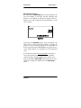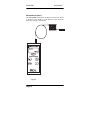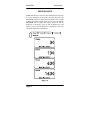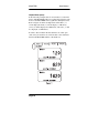
1
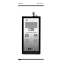
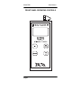
MicrOTDR
™
Optical Fault Locator
User Manual
Datacom Textron
11001 31st Place West
Everett, WA 98204
TEL: 425-355-0590
Toll Free: 800-468-5557
FAX: 425-290-1600
Internet: www.datacom.textron.com
Warranty
The MicrOTDR™ Optical Fault Locator is warranted against defects in
materials and workmanship within a period of two (2) years following the
date of purchase of the tester. Any instrument claimed to be defective during
the warranty period should be returned to Datacom Textron’s Factory
Service Center. (Call Datacom Textron for an RMA number prior to
shipment.)
ANY IMPLIED WARRANTIES ARISING OUT OF THE SALE OF THE
MicrOTDR, INCLUDING BUT NOT LIMITED TO IMPLIED
WARRANTIES OF MERCHANTABILITY AND FITNESS FOR A
PARTICULAR PURPOSE, ARE LIMITED IN DURATION TO THE
ABOVE STATED TWO (2) YEAR PERIOD. DATACOM TEXTRON
SHALL NOT BE LIABLE FOR LOSS OF USE OF THE TESTER OR
OTHER INCIDENTAL OR CONSEQUENTIAL DAMAGES, EXPENSES,
OR ECONOMIC LOSS.
Some states and countries do not allow limitations on how long implied
warranties last or the exclusions or limitation of incidental or consequential
damages, so the above limitations or exclusions may not apply to you. This
warranty gives you specific legal rights, and you may also have other rights
which vary from state to state.
Datacom Textron certifies that this instrument was thoroughly tested and
found to meet its published specifications when shipped from the factory.
MicrOTDR™ Optical Fault Locator User Manual. Copyright 2000 by
Datacom Textron. All rights reserved. Printed in USA. No part of this
document may be used or reproduced in any manner whatsoever, without
written consent of Datacom Textron. Information contained in this document
is believed to be accurate and reliable. However, Datacom Textron may from
time to time make changes to this documentation without notice. Datacom
Textron is not liable for technical or editorial errors or omissions contained
herein. Datacom Textron reserves the right to change the product
specifications at any time without notice.
MicrOTDR™ is a trademark of Datacom Textron. All other product names,
brand names, and services identified in this documentation are the property
of their respective companies.
Printed in USA
P/N 14099 Rev A
MicrOTDR
User Manual
CONTENTS
Page
General ...............................................................4
Safety..................................................................5
Precautions .........................................................6
Front Panel Operating Controls .........................7
Operating Controls .............................................8
Operation............................................................9
Power On............................................................9
Feet/Meters.........................................................9
IOR Selection ...................................................10
Measure ............................................................10
Maintenance .....................................................14
Repair & Calibration........................................14
Battery Replacement ........................................14
Optical Connector Port Maintenance...............15
Optical Connector Maintenance.......................16
Helpful Hints....................................................17
Customer Support ............................................19
Repair ...............................................................19
Technical Assistance........................................19
Specifications ...................................................20
Page 1
MicrOTDR
User Manual
FIGURES
1.
2.
3.
4.
5.
6.
7.
8.
9.
10.
11.
Page
Front Panel Operating Controls...................7
Power On .....................................................9
IOR Selection ............................................10
Laser Active...............................................10
Single Event Measure................................11
Multiple Event Measure ............................11
Multiple Event Measure ............................12
Measuring Length......................................13
Low Battery ...............................................14
Helpful Hints .............................................17
Helpful Hints .............................................18
Page 2
MicrOTDR
Page 3
User Manual
MicrOTDR
User Manual
GENERAL
The MicrOTDR Optical Fault Locator is a rugged, lightweight,
hand-held test instrument for locating faults in multimode and
singlemode optical fiber cable. MicrOTDR utilizes patent pending
OTDR (Optical Time Domain Reflectometer) technology to make
fault location measurements to distances up to 20 kilometers, with
pinpoint accuracy. The unit operates at the industry standard
wavelength of 1310 nm, and displays the distance to a fault in
meters or feet.
The MicrOTDR is designed to measure the distance to fiber
events along fiber cables in optical fiber systems. Useful
applications for the MicrOTDR include testing: Wide Area
Networks (WANs), telecommunication spans of up to 20
kilometers, Fiber-to-the-Curb applications, installation of
multimode and singlemode fiber cabling, and military systems.
The unit is an excellent tool for locating faulty connectors,
damaged components, bad splices and breaks in singlemode and
multimode cable sections. It is also much easier to use than an
OTDR for checking reels of fiber optic cable for length and
defects.
The MicrOTDR has been designed with the technician in mind
with many easy to use features. It has a large LCD display for
viewing ease, and can be used on multimode or singlemode
cables. Its' easy "one button" operation is used for activating the
unit's measure function, and the Index of Refraction (IOR) setting
can be field selected with the use of a single button. The
MicrOTDR is designed to record up to seven events, displaying
the distance to each event.
The MicrOTDR is powered by four AA Alkaline batteries that can
provide greater than 13,000 operations. An advanced power
supply circuit ensures maximum battery life. Sensing circuitry
alerts the operator of "low battery" conditions. The auto power-off
circuit turns the unit off 5 minutes after the last reading to
preserve battery power.
Page 4
MicrOTDR
User Manual
SAFETY
The MicrOTDR Optical Fault Locator is a Class I laser
product under the requirements of both the U.S. Center for
Devices and Radiological Health, and the American National
Standards Institute1. As such, it presents no hazard to users
who view the output when using proper operating procedures.
However, it is recommended that users should not stare
directly into the beam.
Use of controls or adjustments of procedures other than those
specified herein may result in hazardous LASER light
exposure.
It is important to keep all optical connections and surfaces free
from oils, dirt, and other contaminants to ensure proper
operation. Proper cleaning procedures must be performed on
fiber connectors, connector adapters, etc., before conducting
any measurement tests outlined in this manual.
1
American National Standard for Safe Use of Lasers, Publication: ANSI
Z136.I-1993, American National Standards Institute, 11 West 42nd Street,
New York, NY 110036.
Page 5
MicrOTDR
User Manual
PRECAUTIONS
Use care when working with any optical transmission
equipment. It is good practice to avoid looking directly at any
optical fibers or optical sources. The MicrOTDR emits a
pulsed laser light for a short period of time, and the user should
not look directly into the connector port. It is best to refer to
your company's safety procedures when working with optical
fibers or laser based systems.
It is important to keep all optical connections and surfaces free
from dirt, oils or other contamination to ensure proper
operation. This applies to all connectors that are connected to
the optical port on the MicrOTDR, as well as the optical port
on the MicrOTDR itself. Scratched or contaminated
connectors can reduce system performance. Refer to your
company practices for cleaning optical connectors. Always
replace the protective dust cap on the MicrOTDR after use.
Note: This equipment has been tested and found to comply with the
limits for a Class A digital device, pursuant to part 15 of the FCC rules.
These limits are designed to provide reasonable protection against
harmful interference when the equipment is operated in a commercial
environment. This equipment generates, uses, and can radiate radio
frequency energy and, if not installed and used in accordance with the
instruction manual, may cause harmful interference to radio
communications. Operation of this equipment in a residential area is
likely to cause harmful interference in which case the user will be
required to correct the interference at his own expense.
Page 6
MicrOTDR
User Manual
FRONT PANEL OPERATING CONTROLS
Page 7
MicrOTDR
User Manual
OPERATING CONTROLS
Optical Port Connector - The port is equipped with
an ST style connector. The wavelength for this port is 1310nm
and can be used for multimode or singlemode applications.
Liquid Crystal Display (LCD) - When the
MicrOTDR is first powered ON, the unit goes through a selftest, and all display segments, and annunciators are illuminated
on power up.
NOTE: Some of the annuciators illuminated (LINK, and VFL)
on power up are currently not a function used in the
MicrOTDR.
IOR Button - This button selects the Index of
Refraction (IOR) of the optical fiber cable under test. Its range
can be selected from 1.40 to 1.69.
Measure Button
- This button when pressed
activates the MicrOTDR's laser, and digital measuring circuits.
Feet/Meter Button - This button will select either
feet or meters as the unit of measure.
ON Button - This button when depressed turns the
MicrOTDR ON and OFF.
Page 8
MicrOTDR
User Manual
OPERATION
Cable length measurement with the MicrOTDR is simple; just
plug your optical fiber or cable into the MicrOTDR's optical
port connector on top of the unit, press and hold the
MEASURE button, and read the distance in feet or meters.
Power On
To turn the MicrOTDR on, press the ON/OFF button once.
The unit will go through a display test while displaying all
segments and annunciators, after which the MicrOTDR's
software version will display. Figure 2 is the MicrOTDR’s
display after the self-test has been completed, and the
MicrOTDR is ready to be used for measurement.
SELECTING UNIT OF MEASURE
Feet or Meters can be selected as the unit of measure. This
must be done before an actual distance measurement is made.
Press the FEET METERS button to select the desired unit.
Page 9
MicrOTDR
User Manual
IOR
The Index of Refraction of the optical cable under test can be
selected on the MicrOTDR. Refer to Figure 3. Momentarily
depressing the IOR button will display the existing setting.
Depressing and holding the IOR button will cause the setting
to increment. When the desired setting is reached, release the
IOR button, and the setting will remain.
Select the IOR for the fiber optic cable you will be testing for a
wavelength of 1300 nm (multimode) or 1310 nm (singlemode).
Measurements
Attach the fiber optic cable to the MicrOTDR's connector port.
Depress and hold the MEASURE button until the Laser Active
annunciator displays (typically 1.5 seconds), and then release
the MEASURE button. Refer to the Figure 4 below.
Page 10
MicrOTDR
User Manual
Measurements (cont.)
The resulting measurement for a single event will be displayed
as shown in Figure 5. This example shows that the distance to
the EVENT is 31 meters.
When the MicrOTDR detects multiple events, event number
(1) will flash, and the MULTIPLE EVENT annunciator will be
displayed. The distance to event number (1) will then be
displayed, and the event number (1) will extinguish. Refer to
figure 6 below. This example shows that the distance to event
number (1) is 31 meters.
Page 11
MicrOTDR
User Manual
Measurements (cont.)
By depressing the MEASURE button again momentarily, the
next event number (2) will flash, and then extinguish. The
distance to event number (2) will then be displayed. Refer to
Figure 7 below. This example shows that the distance to event
(2) is 72 meters.
Depressing the MEASURE button again momentarily will
show if there is another event. If event number (3) flashes, the
distance to event (3) would be displayed. If event number (1)
flashes, this means that the MicrOTDR has measured only two
events, and the distance to event number (1) will be displayed
again.
If it is desired to initiate a new measurement, for instance, to
verify cable lengths prior to installation, connect the fiber
cable in question to the MicrOTDR's optical connector port.
Depress and hold the MEASURE button until the Active Laser
annunciator is displayed, and then release the MEASURE
button.
Page 12
MicrOTDR
User Manual
Measurements (cont.)
The MicrOTDR will measure the distance to the event. Refer
to Figure 8 below. In this case, the distance to the end of the
fiber cable (event) is 2242 meters.
Figure 8
Page 13
MicrOTDR
User Manual
MAINTENANCE
Repair and Calibration
Repair of the MicrOTDR in the field is NOT recommended. If
the unit is not working, make sure the batteries are good, and
that all connectors, and connector port are clean. If the unit
still will not operate, contact the Customer Service Department
at Datacom Textron at 800/468-5557 or 425/355-0590.
Battery Replacement
The MicrOTDR Optical Fault Locator requires no periodic
maintenance other than cleaning the optical connector port,
and replacing the batteries. Battery life is approximately
13,000 operations. The MicrOTDR will display the Low
Battery annunciator as shown in Figure 9 below when the
batteries require replacement. The battery compartment,
located on the back of the unit, holds four ( 4 ) AA Alkaline
batteries. Four Phillips screws hold the battery compartment
cover in place.
Page 14
MicrOTDR
User Manual
Optical Connector Port Maintenance
All optical connections should be kept thoroughly cleaned. Do
not force any connectors together. Scratches on the optical
connector port will severely affect the performance of the
MicrOTDR. A supply of industry approved optical cleaning
pads, and adapter cleaning wands would be helpful in
maintaining optical connectors, and the MicrOTDR optical
connector port. Also, a can of filtered compressed air is useful
for blowing out any contaminates in the MicrOTDR's optical
connector port, and any connector adapters being used.
The following procedure is recommended to clean the
MicrOTDR's ST optical connector port:
1. Blow out any contaminates in the optical connector port
using a can of filtered compressed air.
2. Carefully clean the optical connector port using a 2.5mm
swab (Datacom Textron Adapter Cleaning Wands).
3. Always replace the dust cap.
Page 15
MicrOTDR
User Manual
Optical Connector Maintenance
It is very important to clean any fiber optic cable connector
that is connected to the MicrOTDR's optical connector port.
The following procedure is recommended to clean the fiber
optic connector:
1. Carefully wipe ferrule with lint-free tissue (Datacom
Textron ReelCleaner™ Connector Cleaning System)
2. Always replace the dust cap.
Page 16
MicrOTDR
User Manual
HELPFUL HINTS
NOTE: The distance to the first event and between events must
be at least 30 meters. If any event is less than 30 meters, the
MicrOTDR will not recognize that event. Refer to the example
in Figure 10. In this example, there are four (4) events that the
MicrOTDR will recognize and display. Event (1) will be
displayed as 30 meters, event (2) will be displayed as 130
meters, event (3) will be displayed as 630 meters, and event
(4) will be displayed as 1630 meters.
Page 17
MicrOTDR
User Manual
Helpful Hints (cont.)
In the following example, there is an event that is less than 30
meters. The MicrOTDR will not recognize this particular event
however; the MicrOTDR will recognize the subsequent events.
Refer to Figure 11. In this example there will be three ( 3 )
events displayed. Event ( 1 ) will be display as 120 meters,
event ( 2 ) will be displayed as 620 meters, and event ( 3 ) will
be displayed as 1620 meters.
In order to detect faults in the first 30 meters of a fiber optic
cable, it may be useful to use a launch cable at least 30 meters
between the MicrOTDR and the cable under test.
Page 18
MicrOTDR
User Manual
CUSTOMER SUPPORT
Repair
If repairs for your Datacom Textron Model MicrOTDR are
necessary, contact Datacom Textron Technical Support at:
Datacom Textron
11001 31st Place West
Everett, WA 98204
TEL (800) 468-5557 or (425) 355-0590
FAX (425) 290-1600
WEB: www.datacom.textron.com
Technical Assistance
Should you need technical assistance with the Model
MicrOTDR, contact Datacom Technical Support at the
following numbers:
(800) 468-5557 or
(425) 355-0590
Page 19
MicrOTDR
User Manual
SPECIFICATIONS
Optical:
Optical Connection
Emitter type
Emitter Classification
Wavelength
Pulse Width
Pulse Rate
Emitter Fiber Type
Index of Refraction
End Measurement Accuracy
Minimum Distance Measured
Dead Zone
Maximum Distance Measured
Minimum detectable signal
@ 10Km
Number of events detected
Operating temp
Storage temp
Single Port
Laser
Class I
1310 nm
200 ns Typical.
500 kHz.
Multimode & Singlemode
1.40 - 1.69
± 2m + IOR Variation
(IOR Variation = 0.67 m/Km
per .001 IOR error)
30m
30m
20 Km
-49 dB
7
-10 to +50°C
-20 to +60°C
Power:
Internal
4 AA Alkaline batteries,
auto power off after 5 minutes
Battery life (Alkaline)
>13,000 operations
Physical:
Dimension
Weight (w/ battery)
Connector Type
Patent Pending
Page 20
7.7 x 4.0 x 1.7 in.
(195 x 100 x 45 mm)
0.9 lbs, (440 g)
ST