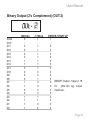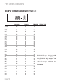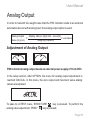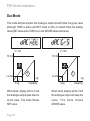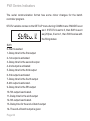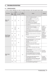
1
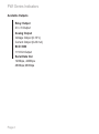
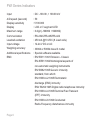
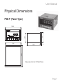
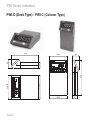
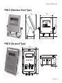
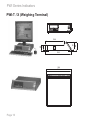
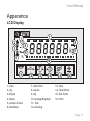
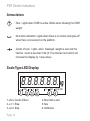
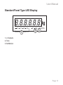
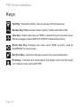
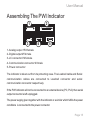
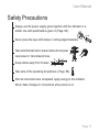
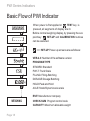
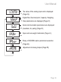
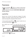
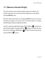
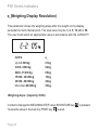
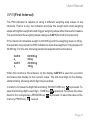
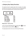
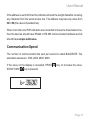
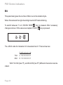
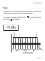
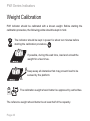
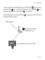
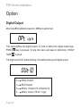
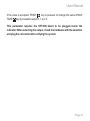
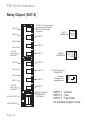
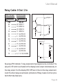
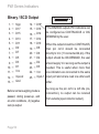
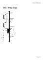
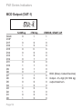
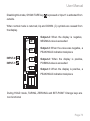
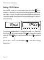
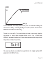
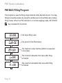
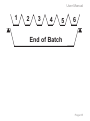
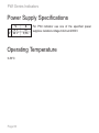
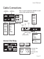
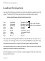
PWI Series Indicators
User Manual
PWI Series
Indicators
User Manual
!
IMPORTANT NOTICE!
In case the indicator you are using is a part of a
scale system that is used for trade, it should be
protected with an official seal and be controlled
every two years.
Contents
Intruduction
Specifications
Technical Specifications
Operation Specifications
Display Specifications
Control Specifications (Option)
Physical Dimensions
Apperance
Displays
Keys
Assembling the PWI Indicator
Safety Precautions
Basic Flow of the PWI Indicator
Parameters
Loadcell Test (LCTEST)
Parameter Entry (SETUP)
Digital Filter
Decimal Point
Scale Type
CAP-E2 (Max. Allowable Weight)
1
3
3
4
5
5
7
11
11
14
15
17
18
20
20
21
21
23
24
25
e2 (Weighing Steps Display Resolution)
CAP-1 (First Interval)
e1 (Weighing Steps Display Resolution)
DRIFT (Zero Drift Correction)
Communication
Adressed Commmunication
Communication Speed
Bit
Parity
Weight Calibration
Gain Adjustment
Zero Calibration
Load Calibration
Option
Digital Output
Relay output (OUT-0
Binary / BCD Output
BCD Output (OUT-1)
Binary Output (2's complement) (OUT-2)
Analog Output
Adjustment Of Analog Output
DAC Mode
Analog Output Adjustment (DACCAL)
26
27
28
29
31
36
37
38
39
40
42
43
44
46
46
48
50
52
53
55
55
56
58
PWI Program Selection
Weight Measurement
Resetting Display Value To Zero
Activating Tare
Showing Tare Value
Disabling Tare Value
Level Control
Transmitting Weight Value From Serial Line
PWI Peak-Hold Indicator Program
PWI Bag Filling Program
PWI Batch Controller Program
Power Supply Controller Program
Operating Temperature
Cable Connections
Loadcell Connection
Communication Cables
Error Codes
64
65
65
66
66
67
67
71
71
76
80
86
86
87
88
90
91
User Manual
Intruduction
PWI Indicator is designed for fast, accurate and high sensitive weight, force and
pressure indication. The indicator can be used with every kind of resistive bridge
sensors.
The indicator was designed for industrial applications and standard weight
measurement fields. The communication with commonly used PLC's has been
taken into account, where they are widely used almost in all the automation
systems. Besides the computer and PLC communication features, the indicator
is also suitable for tank weighing, platform scales and batching systems.
PWI possesses custom designed Liquid Crystal Display for easy operator
dialogue. With the red light LED option of the display, weight can easily be seen
even in the dark environment. The special characters on the display enables the
user to be familiar with the keypad and universal weight and measure icons. The
analogue bar graph makes the weight to be easily understandable by showing
the weight in percentage of the full scale. It possesses a water and dust proof
membrane keypad. All calibration values can be set via this keypad (calibration,
span adjustment, communication mode, parameters, etc.). Designed with SMD
technology.
Page 1
PWI Series Indicators
Available Outputs
Relay Output
4 In / 8 Output
Analog Output
Voltage Output (0-10 V)
Current Output (0-20 mA)
BCD / BIN
1+18 bit Output
Serial Data Out
1200bps, 2400bps
4800bps,9600bps
Page 2
User Manual
Specifications
Technical Specifications
Easily achieved menu steps
Parameter and calibration changes easily done via keypad
Connectable upto ±10 mV/V input (±100 mV)
Sense-Gain adjustment according to sensor output
Tare function enabling zeroing within whole weighing range
250mA at 10 VDC loadcell excitation voltage
90/384 EEC EURO directives and CE approved
Test of all functions during power up
Page 3
PWI Series Indicators
Operating Specifications
Following functions can be fulfilled via keypad
Calibration
Gain adjustment
Communication format and speed
Digital signal filter
Taring
Displaying tare
Zeroing
Displaying excitation and output signals of the sensor
No-motion detection
Center of zero detection (1/4 d)
Warning above maximum allowable weight
Page 4
User Manual
Display Specifications
Specially designed wide viewing-angle LCD or LED display
Analogue bar-graph (LCD display)
7 digital output symbol
2 digital input symbol
Tare indication
Center-of-zero symbol
No-motion detection symbol
Up-down and equal symbols (LCD display)
Showing weight with decimal point (236.910 kg)
Control Specifications (Options)
18+1 Bit BCD or Binary
0-10 V or 4-20 mA analogue output
Control. Formed of 8 outputs, 4 inputs
Page 5
PWI Series Indicators
Input
A/D speed (/second)
Display sensitivity
Display
Maximum range
Communication
Loadcell excitation
Input voltage
Weighing accuracy
Additional specifications
EMC
Page 6
: DC: -100.00 ,+ 100.00 mV
: 50
:1/100.000
: LCD or 7-segment LED
: 6 digit (-199999 +999999)
: RS-232C/RS-485/RS-422
: 250 mA @10 VDC (8 Load cells)
: 12-24 V DC or AC
: 3000d or 5000d class III model
: Special software available
: EN 55011:1991 Emission - Class A
EN 45501:1992 Metrological aspects of
non-automatic weighing instruments
EN 50082:1995 Generic immunity
standard, from which:
EN 61000-4-2:1995 Electrostatic
discharge (ESD) immunity
ENV 50204:1995 Digital radio telephones immunity
EN 61000-4-4:1995 Electrical Fast Transient
(EFT) immunity
EN 61000-4-6:1996 Conducted
Radio-Frequency disturbances immunity
User Manual
Physical Dimensions
PWI-P (Panel Type)
74
65.7
145.8
8.3
136
142.5
142.5
Dimension-Cut Out:137.5x67.5mm
Page 7
PWI Series Indicators
PWI-D (Desk Type) - PWI-C (Column Type)
145.8
56
142.8
145.8
214
35
56
214
142.8
Page 8
35
User Manual
PWI-S (Stainless Steel Type)
170
200
245
200
28
222.5
110
PWI-E (Ex-proof Type)
143
98
10
320
35
237
Page 9
PWI Series Indicators
PWI-T / X (Weighing Terminal)
87
60
55
344
359
349
Page 10
92
244
User Manual
Apperance
LCD Display
1
2
Up
3
EQ
PWI
SP3
SP4
SP5
SP6
SP7
IN1
IN2
0 5
Dn
4
7
SP2
SP1
TT
%
kg9
6
5
8
10 15 20 25 30 35 40 45 50 55 60 65 70 75 80 85 90 95
10
TEST
11
1- Tare
2- Up
3- Equal
4- Down
5- Center of Zero
6- No Motion
0
T
T
SP
12
13
14
15
7- Set-Point
8- Inputs
9- Kg
10- Analog Bargraph
11- Test
12- Zeroing
16
13- Tare
14- Tare Show
15- Set-Point
16- Print
Page 11
PWI Series Indicators
Annuciators
T
Tare : Lights when TARE is active. Blinks when showing the TARE
weight.
No motion indication: Lights when there is no motion and goes off
when there is movement on the platform.
Center of zero: Lights when displayed weight is zero and the
internal count is less than 1/4d (d: The internal count which can
increase the display by 1 step value).
Scale Type LED Display
8.8.8.8.8.8. kg
ZERO
1
2
1- Zero: Center of Zero
2- e1: 1. Step
3- e2: 2. Step
Page 12
e1
e2
3
max
4
P2
TARE
5
NO MOTION
6
4- Max: Max. Load
5-Tare
6- No Motion
User Manual
Standard Panel Type LED Display
8.8.8.8.8.8. kg
SP1
SP2
1
SP3
SP4
P2
TARE
2
NO MOTION
3
1- 4 Outputs
2- Tare
3- No Motion
Page 13
PWI Series Indicators
Keys
Test Key: Tests all functions. Device acts as if first powered-up.
0
Zeroise Key: Makes screen value 0 (zero) if within allowable limits.
Tare Key: Used to set value as TARE or disable the previous tare value.
Works as toggle uses as MOVE CURSOR in parameter entires.
Show Tare Key: Displays tare value when TARE is active, used as
INCREMENT in setup mode.
Set-Point Key: Used for entering menus for set-up and calibration.
Print Key: Transmits the serial data of the weight value from the serial
out. In setup mode used as ENTER.
Page 14
User Manual
Assembling The PWI Indicator
2
1
3
4
5
1- Analog output 15'd female
2- Digital output 25'd male
3- LC connector 9'd female
4- Communication connector 9'd male
5- Power connector
The indicator is taken out from its protecting case. The Loadcell cable and Serial
communication cables are connected to Loadcell connector and serial
communication connector respectively.
If the PWI indicator will not be connected to an external device (PC, PLC) then serial
output connector is left unplugged.
The power supply given together with the indicator or a similar which fulfills the power
conditions is connected to the power connector.
Page 15
PWI Series Indicators
When energy is applied from the power connector, the device starts working with the
TEST procedure ( Page: 18).
Since analog output, 0(4)-20mA or 0-10V; digital output are optional, they do not exist
on a standard device. The user must state the necessary options before demanding
the device. The user needs an external power supply of 18-24 VDC for 0(4)-20
mA or 0-10 V analog output option.
If cable connections will be done by your side see Page: 88 for connections.
Page 16
User Manual
Safety Precautions
Always use the power supply given together with the indicator or a
similar one with specifications given in (Page: 86).
TES
T
Never press the keys with sharp or cutting edged materials.
Take care that load cell or power cables do not pass
near power or transmission lines.
Keep cables away from bruises.
Take care of the operating temperature ( Page: 86).
After all connections are completed, apply energy to the indicator.
Never make changes in connections when power is on.
Page 17
PWI Series Indicators
Basic Flow of PWI Indicator
When power is first applied or
TEST key is
pressed, all segments of display are lit.
Before normal weighing display, by pressing the setpoint key
SET-UP and CALIBRATION routines
can be executed.
?
?
.3
>>> SET-UP Power-up screens are as follows:
?
?
?
kg
?
WEIGHING
Page 18
VER-4.3: Number of the software version
PROGRAM TYPE
STNDRD: Standard
PWI-T: Truck Scale
FILLNG: Filling-Batching
DOSAGE:Dosage Batching
HOLD:Peak and Hold
AXLE: Static/Dynamic axle scale
ESIT: Manufacturer company
CHECK-SUM Program control code
CAPACITY: Maximum allowable weight
User Manual
The value of the analog input and is displayed
(Page:18)
Digital filter, Decimal point, Capacity, Weighing
Step parameters are displayed (Page:21)
Serial communication parameters are displayed
(baudrate, bit, parity) (Page:31)
Span and real weight Calibration (Page:41)
Relay or BCD/BIN option parameters selection
(Page:46)
Adjustment of Analog Output (Page:55)
Page 19
PWI Series Indicators
Parameters
After power is first applied or
TEST key is pressed, by simply pressing
the
SET-POINT key , the PARAMETER menus can be executed. These
menus are formed in six main groups: LCTEST, SETUP, COMM, CALIBR,
OPTION and DACCAL.
Load Cell Test
Within this menu, the value of the analog input is displayed. The millivolt
calibration of the indicator is factory set and cannot be changed later. The
maximum input range of the analog input is ±100mV (±10mV/V).
In order to enter this routine PRINT key
is pressed. To switch to the next
menu, SETUP, SHOW-TARE key
is pressed.
When LCTEST menu is entered, on the right hand side of the screen
appears.
kg
IN1
SP1
To exit the menu TEST
Page 20
key is pressed.
SP2
SP3
SP4
P2
TARE
NO MOTION
User Manual
Parameter Entry (Setup)
In this menu, Digital Filter, Decimal Point, Weighing Capacity, Weighing Steps
and Drift parameters are displayed and can be changed.
In order to enter this routine, PRINT
key is pressed. To switch to next menu
(COMM) SHOW TARE
key is pressed.
The mechanical vibration and electrical noise
can be filtered out by this parameter
The decimal point used when displaying the weight
MULRNG,MULINT SINGLE
Maximum allowable
weighing range
The weighing
resolution
First weighing range
value
Weighing resolution
until first weighing
range
Zero drift correction
0: Tare disabled. 1: Pushbutton Tare
Page 21
PWI Series Indicators
FILTER MODE:
FILTR.0 : Speedy measurement. (Recommended for Hold Programme)
FILTR.1 : Normal measurement. (Recommended for Standard Programme)
FILTR.2 : Slow measurement. (Recommended for PWI-T Programme)
FILTR.3 : Coarse filling. (Recommended for Filling Programme)
FILTR.4 : Fine filling. (Recommended for Filling and Batching Programs)
FILTR.5 : Custom set. User can adjust the filter parameters.
FILTER SPAN: Acceptable maximum changing value of screen.
VB.TM: Vibration time. (0.0-9.9 sec)
BUFFER SIZE: Average.
BUFFR.0: Averaged 2 sample.
BUFFR.1: Averaged 4 sample.
BUFFR.2: Averaged 8 sample.
BUFFR.3: Averaged 16 sample.
BUFFR.4: Averaged 32 sample.
CERTF: (1) shows whether the indicator is dependent on the regulation of
weighing authorities.
If CERTF=1, do not allowed DRIFT and zeroing if over %2 of the capacity.
BG.ZRO: (1) If the screen value less than %20 of the capacity, can be
automatically zeroed at the power up. (beginning of the weighing)
Page 22
User Manual
Decimal Point
When the display resolution needs decimal point for fractional values, it is
possible to show it on the display.
The value next to DOT is the number of digits on the right of decimal point. It
blinks to show it is being edited.
If the value on the display is accepted, PRINT
key; to increase the value,
SHOW TARE
key is pressed. The allowable values are: 0, 1, 2, 3.
CAP-2+9e2
CAP-2
e=e2
CAP-1+9e1
CAP-1
e=e1
0.000 kg
Page 23
PWI Series Indicators
Scale Type
The indicator may be configured with two weighing ranges with two different
weighing resolutions to enable higher accuracy readings in lower values.
There are three different modes to select from:
Single interval
Multi-interval
Multi-range
In single interval mode, there is only one range and one resolution; in the
others there are two ranges and resolutions.
Page 24
User Manual
CAP-2 (Maximum Allowable Weight)
This value determines the maximum weighing range of the indicator. The
indicator will produce an error code when the weight value on the platform
exceeds CAP2+9e2 value.
When this routine is first entered, on the display CAP2 text is seen for a second
and leaves the display to its numeric value. The left-most digit on the display
starts blinking showing which digit may be edited.
In order to increase the digit that is blinking, SHOW TARE key
is pressed. To
pass the blinking digit to next digit, TARE key
is pressed. To reduce the value
down to 0 in a single step, ZEROISE key 0 is pressed. To save the value in the
memory, PRINT key
is used.
Page 25
PWI Series Indicators
e2 (Weighing Display Resolution)
This parameter shows the weighing steps after the weight on the display
exceeds the multi-interval point. The step value may be 1, 2, 5, 10, 20 or 50.
The user must select an appropriate value in accordance with the CAPACITY.
CAP-2
e2
Up to 3 000 kg
3 000 - 6000 kg
6000 - 15 000 kg
15 000 - 30 000 kg
30 000 - 60 000 kg
More than 60 000 kg
01 kg
02 kg
05 kg
10 kg
20 kg
50 kg
Weighing steps ³
(Capacity / 3000)
In order to change the WEIGHING STEP value; SHOW TARE key
To save the value in the memory, PRINT key
is used.
Page 26
is pressed.
User Manual
CAP-E1 (First Interval)
The PWI indicator is capable of using 2 different weighing step values in two
intervals. That is to say, the indicator will show the weight with small weighing
steps with lighter weight and with bigger weighing steps when the load increases.
The point where the weighing steps change is CAP1(the multi interval point).
If the maximum allowable weight is 60.000 kg and the weighing steps is 20 kg,
the operator may adjust the PWI indicator to show the weights in 10 kg steps until
30.000 kg. For this, the following parameter adjustment must be done
CAP-2
e2
CAP-1
e1
60 000 kg
20 kg
30 000 kg
10 kg
When this routine is first entered, on the display CAP-E1 is seen for a second
and leaves the display to the numeric value. The left-most digit on the display
starts blinking, showing which digit may be edited.
In order to increase the digit that is blinking; SHOW TARE key
is pressed. To
pass the blinking digit to next digit, TARE key
is pressed. To reduce the value
down to 0 in a single step, ZEROISE key 0 is pressed. To save the value in the
memory, PRINT key
is used.
Page 27
PWI Series Indicators
e1 (Weighing Steps Display Resolution)
This parameter shows the weighing steps before the weight on the display
exceeds the multi-interval point. The step value may be 1, 2, 5, 10, 20 and 50. The
user must select an appropriate value in accordance with the CAPACITY.
(CAP-1)
Up to 3000 kg
3000 - 6000 kg
6000 - 15 000 kg
15 000 - 30 000 kg
30 000 - 60 000 kg
Above 60 000 kg
(e1)
01 kg
02 kg
05 kg
10 kg
20 kg
50 kg
Weighing steps ³
(Capacity / 3000)
In order to change the WEIGHING STEP value; SHOW TARE key
To save the value in the memory, PRINT key
is used.
is pressed.
The weighing step resolution can be seen on SCALE type PWI indicators.
Page 28
User Manual
8.8.8.8.8.8. kg
ZERO
e1
e2
max
P2
TARE
NO MOTION
DRIFT (Zero Drift Correction)
Zero drift correction parameter is designed to counter the effects of rain, snow or
dirt collecting on the platform, which would otherwise cause cumulative errors.
When enabled, the zero condition is maintained for very slow, small changes
occurring in the measured weight of the platform, as long as the changes are
within the usual half of the weighing steps deviating from the true zero value.
Note: This mode may be in contravention of some Weight & Measures
Authorities Regulations, therefore should be set to 0.
Since this zeroing is not stored in the non-volatile memory like the calibration
zero or the user zero, unplugging the indicator or pressing the TEST key
will
bring back the last key-pressed zero value. If the operator wishes to enable this
feature, then DRIFT variable should be set as 1 otherwise as 0.
During the time TARE is active, DRIFT feature is disabled.
Page 29
In order to toggle the DRIFT value, SHOW TARE
value in the memory, PRINT
key is used.
key is pressed. To save the
e1
1/2e1
0 kg
-1/2e1
-e1
Drift automatically readjusts the scale to zero for compensating selected small
deviation per 2 second around center of zero.
1=0,5e
2=2e
3=3e
4=4e
5=5e
6=6e
7=7e
8=8e
9=9e
User Manual
Communication Parameters (COMM)
0: 5 digits 1: 6 digits weight value is sent.
The weight data is sent in 5 or 6 digits following
the user defined prefix character. The character
is entered decimal.
Page 31
PWI Series Indicators
¨
RS-232
¨
RS-485
¨
RS-422
The value next to MODE shows the communication mode. If the value on the
display is accepted, PRINT
key; to increase the value, SHOW TARE
key is
pressed. The allowable values are: 0, 1, 2, 3, 4.
MODE 0
MODE 1
MODE 2
MODE 3
MODE 4
MODE 5
MODE 6
MODE 7
MODE 8
No communication
Continuous transmission of 6-digit weight value
Continuous transmission of weight, tare and status
Addressed communication mode 6 digit weight value
For axle scale
MODBUS
Hold mode
Transferred barcode (read from serial barcode reader) with weight value.
Designed for Esit FIXUM indicator communication format.
MODE 0: Disables communication feature. In this mode PRINT
enabled and protocol bits are not edited.
key is not
MODE1: The indicator transmits the weight value in continuous mode with the
following format. The data consists of 8 bytes.
Page 32
User Manual
Display
31249 kg '+'
HEX 2B
'0'
30
'3'
33
'1'
31
'2'
32
'4'
34
'9'
39
CR
0D
-5780 kg '-'
HEX 2D
'0'
30
'0'
30
'5'
35
'7'
37
'8'
38
'0'
30
CR
0D
1.600 kg '+'
HEX 2B
'0'
30
'0'
30
'1.'
B1
'6'
36
'0'
30
'0'
30
CR
OD
Character
0.
1.
2.
3.
4.
CDot:
0
HEX
B0 (30+80)
B1 (31+80)
B2 (32+80)
B3 (33+80)
B4 (34+80)
Character
5.
6.
7.
8.
9.
HEX
B5
B6
B7
B8
B9
(35+80)
(36+80)
(37+80)
(38+80)
(39+80)
If there is a decimal point on the display, then the corresponding digit
is sent with hex80 added to the ASCII value.
1 Sent "." 2E (HEX)
Page 33
PWI Series Indicators
MODE- 2 : For a more detailed data this communication mode is selected. Within
the data, STATUS, DISPLAY value and TARE value are sent. The data consist of 18
bytes.
TARE
WEIGHT
STX SW1 SW2 SW3 0 1 2 9 6 5 0 0 0 0 0 0 CR CHX
02 2D 30 20
30 31 32 39 36 35 30 30 30 30 30 30 0D XX
bits 7
0
6 5 4 3 2 1 0
0 1 0 0 0 0 0
this byte is fixed, always same data
bits
bits
Page 34
7
0
7 6 5 4
0 0 1 1
6 5
0 1
3
motion
yes (0)
4 3 2
Weighing steps
(1 kg) 0 1 1
(2 Kg) 1 1 0
(5 kg) 0 1 1
(10 kg) 1 0 0
(20 kg) 1 0 1
(50 kg) 1 1 0
2
err
(0)
1
neg
(1)
0
tare
yes (1)
1 0
Decimal point
(0) 0 0
(1) 0 1
(2) 1 0
(3) 1 1
User Manual
This is a standard format used in most of the weighing indicators. The DATA for a
system with Tare value is 1250 kg, Weighing Steps is 1, Decimal point 0 is as
follows: (7 bits)
Display
31249 kg
WEIGHT
TARE
0, 3, 1, 2, 4, 9, 0, 0, 1, 2, 5, 0, CR, CHX
HEX 02, 3D,20,30,33,31,32,34,39,30,30,31,32,35,30,0D,BB
MODE 3: The communication of weight value is performed when the indicator
realizes the code from the other side. By this way; more than one indicator can be
connected to the, same communication line. The data format is same as
MODE1, the only difference is that the data is transmitted only when demanded
from serial line or by pressing PRINT
key.
In this mode, when pressing the PRINT
if the code was received.( Page: 29 )
key, the same data is transmitted as
Up
EQ
SP1
TT
SP2
SP3
SP4
SP5
SP6
SP7
%
kg
5
Up
10 15 20 25 30 35 40 45 50 55 60 65 70 75 80 85 90 95
0
TEST
EQ
SP1
TT
T
SP2
SP3
SP
T
SP4
SP5
SP6
SP7
kg
5
Up
10 15 20 25 30 35 40 45 50 55 60 65 70 75 80 85 90 95
0
TEST
EQ
SP1
TT
T
SP2
SP3
SP
T
SP4
SP5
SP6
SP7
kg
5
Up
10 15 20 25 30 35 40 45 50 55 60 65 70 75 80 85 90 95
0
TEST
EQ
SP1
TT
T
SP2
SP3
SP
T
SP4
SP5
SP6
%
SP7
IN1
IN2
0
kg
Dn
TEST
IN1
IN2
0
Dn
%
IN1
IN2
0
Dn
%
IN1
IN2
0
Dn
5
10 15 20 25 30 35 40 45 50 55 60 65 70 75 80 85 90 95
0
T
T
SP
For a PC to communicate with more than one indicator, this parameter should be
set to MODE 3, and the communication hardware should be RS-422 or RS-485.
Page 35
PWI Series Indicators
Addressed Communication
After MODE 3-MODE 5 is selected and PRINT
will be waiting for its address.
key is pressed, the indicator
When first entered the right-hand digit next to Adr starts blinking.
increase the digit value of the blinking digit, SHOW TARE
key; to pass to next
digit, TARE
key; to set the blinking value to zero, ZEROISE 0 key; to accept
the whole value, PRINT
key should be pressed.
In order to communicate with a PWI indicator, the PC or the PLC should first
transmit a WAKE-UP code (HEX FF), followed by the address given with this
parameter.
Example: If Adr is set as 31 the indicator will send the weight data after receiving
HEX
Page 36
(Wake up)
(FF)h
'1'
(31)h
User Manual
If the address is set to 00 then the indicator will send the weight data after receiving
any character from the serial receive line. The Address may take any value from
00 to 99 (the value is hexadecimal).
When more than one PWI indicators are connected to the same transmission line,
then the devices should have RS422 or RS 485 communication hardware and all
should have unique addresses.
Communication Speed
The number of communication bits sent per second is called BAUDRATE. The
selectable values are: 1200, 2400, 4800, 9600.
If the value on the display is accepted, PRINT
SHOW TARE
key is pressed.
key; to increase the value,
Page 37
PWI Series Indicators
Bit
This parameter gives the number of bits in a communication byte.
When first entered the right-hand digit next to BIT starts blinking.
To switch between 7 to 8, SHOW TARE
key is pressed. After necessary
change is done or if the value is accepted, PRINT
key is pressed.
The ASCII code for character 'A' is hexadecimal 41. This is shown as:
7 bit
8 bit
7 6 5 4 3 2 1 0
x 1 0 0 0 0 0 1
0 1 0 0 0 0 0 1
With 7 bit 128 (hex 7F), and 8 bit 256 (hex FF) different characters can be
coded.
Page 38
User Manual
Parity
This parameter is used for transmission data control purposes. This is in fact a
control bit within a character. It can be set as NO, ODD or EVEN
key; to change the value,
Start bit
Parity bit
If the value on the display is accepted, PRINT
SHOW TARE
key is pressed.
+3V
Stop bit
Stop bit
-3V
LSB
©
tª
MSB
t(s)=1/baudrate
Page 39
PWI Series Indicators
Weight Calibration
PWI indicator should be calibrated with a known weight. Before starting the
calibration procedure, the following points should be kept in mind.
The indicator should be kept in power for about ten minutes before
starting the calibration procedure.
If possible, during this wait time, load and unload the
weight for a few times.
Keep away all obstacles that may prevent load to be
sensed by the platform.
The calibration weight should better be approved by authorities.
The reference weight should better be at least half of the capacity.
Page 40
User Manual
RATE Conversion speed.
(6, 12, 25 and 50 sample/sec).
SPAN value is adjusted
When there is no load on the platform it is
introduced to the indicator
When load is placed, it is entered to the indicator
Page 41
PWI Series Indicators
Gain Adjustment
When CALIBR is seen on the display by pressing the PRINT
key, Gain
Adjustment step can be performed. This adjustment should be done according to
the output of the analogue signal. When it is set correctly, the indicator will have
better performance.
When first entered the right-hand digit next to LC starts blinking.
If the value on the display is accepted, PRINT
SHOW TARE
key is pressed.
Analog Input (mV/V)
between 0.1 - 1.1
between 1.1 - 2.2
between 2.2 - 4.5
between 4.5 - 9.9
key; to increase the value,
Gain
1.25
2.50
5.00
10.0
When GAIN selection is done, the value should be set as the nearest higher
output value given in the above table.
Page 42
User Manual
Zero Calibration
In order to introduce the empty platform value to the device, Zero Calibration
should be performed. For a short time ZERO is seen on the display.
Then it leaves to the internal count value.
After the platform is emptied, ZEROISE 0 key is pressed. The internal count
value will be reduced to a value around zero. If the previously entered “Zero
Calibration” is not to be changed, the operator should press PRINT
key to
pass to the next step, the CALIBRATION.
Page 43
PWI Series Indicators
Load Calibration
To introduce the value of the known weight LOAD CALIBRATION should be
performed. After Zero calibration routine is exited, for a short time LOAD is
displayed.
This message will leave the display to the internal count value.
26354ı
If needed, during this time ZEROISE 0 key can be pressed again. The weight
is placed on the platform. When the no-movement state is achieved,that is to
say, the internal count value reaches stability, SETPOINT
key is pressed to
enter the section where the weight of the load is written to the indicator.
Page 44
User Manual
In order to increase the blinking digit by one, SHOW TARE
key; to pass to
next digit, TARE
key ; to make the blinking value zero, ZEROISE 0 key;
finally to accept the written value, PRINT
key is pressed.
After the weight value is written and PRINT
will start the TEST procedure.
key is pressed, the PWI indicator
GAIN is selected.
0
When platform is empty,
ZEROING is done.
Load is placed and its value is written.
Page 45
PWI Series Indicators
Option
Digital Output
After CALIBR (calibration) section, MENU is performed.
This value defines the digital output. In order to define the digital output type,
PRINT
key is pressed. To skip this menu and pass to (DACCAL), SHOW
TARE
is used.
The digit next to OUT starts blinking. This defines the type of digital output.
0
1
2
3
Page 46
Relay Output.
BCD Output
Binary Output (2's complement)
Binary Output (18 bit + sign)
User Manual
If the value is accepted, PRINT
key is pressed. to change the value SHOW
TARE
key is pressed to select 0, 1, 2 or 3.
This parameter requires the OPTION board to be plugged inside the
indicator. When selecting the output, check the hardware with the selection
and plug the connector after verifying the system.
Page 47
PWI Series Indicators
Relay Output (OUT-0)
INPUT 8
INPUT 7
OUTPUT 8: Activates during
normal weighing. Disables
when error or start up is
performed.
OUTPUT 7
+24
INPUT
CONNECTOR Signal
GND
INPUT 6
OUTPUT 6
INPUT 5
24 V DC
16-20 V AC
10W INPUT
INPUT 4
INPUT 3
OUTPUT 5
24 V DC
16-20 V AC
10W INPUT
18 V AC OUTPUT
220 V AC INPUT
Page 48
24 V DC
16-20 V AC
10 W
OUTPUT 4
OUTPUT 3
INPUT 2
INPUT 1
POWER
CONNECTOR
OUTPUT 2
OUTPUT (250 V 10 A)
CONNECTOR
Common
Normally open
Normally closed
Com.
N.O.
N.C.
OUTPUT 1
RELAY CONTROL
CONNECTOR
(25'D MALE)
INPUT 1 : Zeroise
INPUT 2 : Tare
INPUT 3 : Tare Show
for standard program mode.
User Manual
Relay Cable: 8 Out / 2 In
25 Pin Female
25 Pin Female
23
PWI
25.
12.
2.
14.
23.
10.
22.
9.
21.
8.
20.
7.
13.
RELAY
22 INPUT-1
10 INPUT-2
23 INPUT-3
11 INPUT-4
17 OUTPUT-1
4 OUTPUT-2
16 OUTPUT-3
3 OUTPUT-4
15 OUTPUT-5
2 OUTPUT-6
14 OUTPUT-7
1 OUTPUT-8
6, 7, 8, 19, 20 GND
10
13
Output-1
Output-2
Gnd
INPUT-1
25
10 K
Gnd
13
By using a PWI indicator, 7 relay output and 2 input signal can be controlled. The
set-point, SP, which is activated on the display is also output simultaneously on
the relay output. If on the display SP2, SP5 are lit, then on the relay output card,
2 and 5 number relays are activated. (Activation of Relay means Common pin is
tied to Normally Open pin).
Page 49
PWI Series Indicators
Binary / BCD Output
1. "
Sign
2. "
D17
D15
3. "
D13
4. "
D11
5. "
D9
6. "
D7
7. "
D5
8. "
D3
9. "
D1
10. "
Vcc
11. "
Input-2
12. "
Gnd
13. "
14. "
D18*
* The BIN/BCD outputs PWI indicators can
15. "
D16
be configured as CONTINUOUS or OND14
16. "
DEMAND by the user.
D12
17. "
D10
18. "
When the output should be CONTINUOS,
D8
19. "
then pin no14 should be connected
D6
20. "
directly to Vcc (11 connected 24 pin). If the
D4
21. "
output should be ON-DEMAND, the user
D2
22. "
should supply Vcc as long as the output is
D0
needed. This is useful when more than
23. "
Vcc
one indicators are connected to the same
24. "
Input-1 input port and all are read one after each
25. "
Before normal weighing mode is
passed, during power-up, and
on error conditions, -0 (negative
zero) is output.
Page 50
other.
As long as the pin no14 is left idle (noconnection), no output can be received
from outside (open collector output).
User Manual
BCD / Binary Output
Vcc
Output-1
D0
23
10K
Output-2
D1
10
13
Gnd
Page 51
PWI Series Indicators
BCD Output (OUT-1)
SIGN
D18*
D17
D16
D15
D14
D13
D12
D11
D10
D9
D8
D7
D6
D5
D4
D3
D2
D1
D0
Page 52
12495 kg
0
0
1
0
0
1
0
0
1
0
0
1
0
0
1
0
1
0
1
-1780 kg
1
0
0
0
0
0
1
0
1
1
1
1
0
0
0
0
0
0
0
ERROR, START-UP
1
0
0
0
0
0
0
0
0
0
0
0 BCD (Binary Coded Decimal)
0 Output. 4½ digit (39 999 kg)
0 output maximum.
0
0
0
0
0
User Manual
Binary Output (2's Complement) (OUT-2)
2
SIGN
D18*
D17
D16
D15
D14
D13
D12
D11
D10
D9
D8
D7
D6
D5
D4
D3
D2
D1
D0
12495 kg
0
0
0
0
0
1
1
0
0
0
0
1
1
0
0
1
1
1
1
-1780 kg
1
1
1
1
1
1
1
1
0
0
1
0
0
0
0
1
1
0
0
ERROR, START UP
1
0
0
0
0
0
0
0
0
0
0
0 BINARY Output. 1(sign) + 18
(262.143 kg) output
0 bit
0 maximum.
0
0
0
0
0
Page 53
PWI Series Indicators
Binary Output (Absolute) (OUT-3)
3
SIGN
D18*
D17
D16
D15
D14
D13
D12
D11
D10
D9
D8
D7
D6
D5
D4
D3
D2
D1
D0
Page 54
12495 kg
0
0
0
0
0
1
1
0
0
0
0
1
1
0
0
1
1
1
1
-1780 kg
1
0
0
0
0
0
0
0
1
1
0
1
1
1
1
0
1
0
0
ERROR, START-UP
1
0
0
0
0
0
0
0
0
0
0
BINARY Output. 1(sign) + 18
0
bit
(262.143 kg) output.The
0
value
is output without the
0
0
dot value.
0
0
0
0
User Manual
Analog Output
In order to transmit the weight value that the PWI indicator reads to an external
automation device with analog input, the analog output option is used.
Analog Output
Display Value x (High Val. - Low Val.)
=
+ Low Value
Weighing Capacity
Value (V) (mA)
Adjustment of Analog Output
V
A
PWI indicator analog output needs an external power supply of 18-24 VDC.
In the setup section, after OPTION, the menu for analog output adjustment is
reached: DACCAL. In this menu, the zero output and maximum value analog
values are adjusted.
To pass to LCTEST menu, SHOW TARE
key is pressed. To perform the
analog value adjustment, PRINT
key is pressed.
Page 55
PWI Series Indicators
Dac Mode
This mode defines whether the Analogue output should follow the gross value
(although TARE is active and NET mode is ON), or should follow the display
value (NET value when TARE is on, and GROSS value otherwise)
V / mA
V / mA
Hi-Val
Hi-Val
TT
Lo-Val
kg
0 kg
Capacity
When tared, display will be 0 and
the analogue output goes down to
Lo-Val value. This mode follows
NET value.
Page 56
TT
Lo-Val
kg
0 kg
Capacity
When tared, display will be 0 but
the analogue output will keep the
value. This mode follows
GROSS value.
User Manual
The difference can be seen on LCD displays as follows:
kg
%
5
When tared,
10 15 20 25 30 35 40 45 50
TT
TT
0
0
kg
%
%
DAC.NET
DAC Mode change is done by SHOW TARE
key is pressed
0.000 kg
5
10 15 20 25 30 35 40 45 50
DAC.GRS
key . To store the value, PRINT
Page 57
PWI Series Indicators
Analog Output Adjustment (DACCAL)
Dn
This value determines the analogue output when the platform is empty.
Dn
To increase the value by 1, SHOW TARE
key is used when the right hand
digit is blinking. To decrease by 1, SET-POINT
key is used. To switch
between 1 by 1 and 10 by 10, TARE
key is used. Then SHOW TARE
and
TARE
keys will change the values by 10. The ZEROISE 0 key will set the
whole value down to 0. When the value is adjusted correctly, PRINT
key is
used to save the value.
The value that is seen on the screen of the meter is the value that the indicator
will produce when there is no load on the platform. If the user wants to use 4-20
mA, then this value should be set to 4mA (the device can output 0 to 20 mA).
Up
Page 58
User Manual
Then, the upper value is adjusted. This value is the value that is produced when
the weight on the platform reaches the CAPACITY value.
Up
Just like adjusting the lower value, the same keys are used for adjusting the
upper value. To increase the value by 1, SHOW TARE
key is used when the
right hand digit is blinking. To decrease by 1, SET-POINT
key is used. To
switch between 1 by 1 and 10 by 10, TARE
key is used. Then SHOW TARE
and TARE
keys will change the values by 10. The ZEROISE 0 key
will set 4095. When the value is adjusted correctly, PRINT
key is used to
save the value.
The value that is seen on the screen of the meter is the output that the indicator
will produce when the load is equal to the MAXIMUM CAPACITY value.
Page 59
PWI Series Indicators
Analog Output (V)
If the CAPACITY is set to 1000 kg, the signal
from analog output is 10V, when 500 kg is
seen, the value is 6V and with no load 2V is
read.
10
6
2
0
-250
0
500
1000 Capacity (kg)
Analog Output (mA)
If the CAPACITY is set to 5000 kg, the output
from analog output is 20mA, when 1250 kg is
seen, the value is 8mA and with no load 4mA
is read
20
8
4
0
-1250
0
1250
5000
Capacity (kg)
In order to get the desired output, either voltage or current, the following
short circuits must be done.
Page 60
User Manual
0-10V analogue output;
8. + Power 18-24Vdc
6. - Power 18-24Vdc
(GND)
10-11. + (0-10)V Output
13-14. - (0-10)V Output
(GND)
0-10V
Between pins 10 and 11, should be shorted to each other
Between pins 13 and 14, should be shorted to each other
The 0-10V output is read between these two short circuited pins.
18-24V power supply is connected to 8 pin on positive pole, and to 6 pin
on the negative pole.
Page 61
PWI Series Indicators
4-20mA analogue output (Source mode);
8. + Power 18-24Vdc
6. - Power 18-24Vdc (GND)
1-3. Short Circuit
2-10-14. Short Circuit
10. +(4-20)mA Output
13. -(4-20)mA Output
4-20mA
P
W
I
8
+Vdd (18-24Vdc)
1
3
2
10
14
+4-20mA
13
6
-4-20mA
+Ain
-Ain
-Vdd
Between pins 1 and 3, should be shorted to each other
Between pins 2-10 and 14, should be shorted to each other
18-24V power supply is connected to 8 pin on positive pole, and to 6 pin on
the negative pole.
The 0-20mA output is read between 10 (+4-20mA) and 13 (-4-20mA).
If the device is to be connected has no internal resistance (0 W
), then4-20mA
output is taken from pin no 12 not 13.
Page 62
User Manual
4-20mA analogue output (Sink mode);
4-20mA
8
P
W
I
+Vdd (18-24Vdc)
1
3
2
10
14
13
6
8. + Power 18-24Vdc
6. - Power 18-24Vdc (GND)
2-10-13-14. Short Circuit
1. + (4-20)mA Output
3. - (4-20)mA Output
+Ain
-Ain
-Vdd
Between pins 2-10-13 and 14, should be shorted to each other
The 0-20mA output is read between 1 (+output) and 3 (-output).
18-24V power supply is connected to 8 pin on positive pole, and to 6 pin on
the negative pole.
If the device is to be connected has no internal resistance (0 W
), then 2-1014. must be short circuit. 12-13. should be short circuit.
Page 63
PWI Series Indicators
PWI Program Selection
PWI indicator may be configured to run software that is relevant to the
application. Only the usage is different, no calibration change or correction is
needed, therefore the user may change the user software without breaking the
calibration seal (if exists). During order, if the usage is stated, then the program
comes with the desired usage, otherwise STANDARD Program is set. Besides,
during order, necessary option outputs must also be stated.
The various program selection is as follows:
Standard
Truck scale
Bag filling scale
Batching (up to 6 materials)
Peak-Hold indication
Axle scale
The change of the program can be learned from technical service.
Page 64
User Manual
Weight Measurement
If during TEST procedure, no key is pressed, the indicator will start showing the
weight on the platform. In this mode, Zeroing, Tare activating, setpoint control
and weight value transfer can be performed.
5.385 kg
%
5
5.385
10 15 20 25 30 35 40 45 50
SP1
SP2
SP3
SP4
P2
TARE
kg
NO MOTION
Resetting Display Value To Zero
To reset the weight value to zero, ZEROISE 0 key is pressed. In order to
perform this function, the indicator should be in no-movement state which can
be realized with the
symbol is lit and TARE should be not active.
0
0.000 kg
0.000 kg
%
SP1
SP2
SP3
SP4
P2
TARE
NO MOTION
After ZEROISE 0 key is pressed, the value turns to zero and center-of-zero
0 (LCD) - o (LED) symbol is lit.This may happen only if the value is within
user resetable value.
Page 65
PWI Series Indicators
Activating Tare
If the NET mode is desired, TARE function should be activated by pressing the
TARE
key. When there is movement, i.e. the
symbol is not on, this key
is ignored.
TT
0
0.000 kg
0.000 kg
%
SP1
SP2
SP3
P2
SP4
TARE
NO MOTION
When tare is activated, the display will be zero and Tare symbol is lit. In order to
TARE a value, the weight on the platform must be positive. When TARE is active,
ZEROISE 0 key and function are disabled.
Showing Tare Value
When TARE is active, the operator can see the Tare value as long as the SHOW
TARE
key is pressed.
TT
5.385 kg
5.385
SP1
SP2
SP3
SP4
P2
TARE
kg
NO MOTION
To show that the value displayed is the tare value the TARE symbol blinks.
Page 66
User Manual
Disabling Tare Value
When tare is active, pressing the TARE
key again, will disable the TARE
function and the gross weight on the platform is displayed, that is to say, the
device is in the GROSS mode. The TARE symbol goes off.
Level Control
PWI Indicator possesses 7 digital set-point indication on the display. These are
used to warn the operator whether the value is under or over the desired set
values. In order to enter these set values SET-POINT
key is pressed for 3
seconds.
ı-0
ı-0
SP1
SP2
SP3
SP4
P2
TARE
kg
NO MOTION
On the display
symbol and SET1 is displayed. The 0 or 1 on the right hand
side can be changed by pressing SHOW TARE
key. The symbols UP and
DOWN are lit according to this value. If the value is 0 and the DOWN symbol is
lit, during weight measurement, the related set-point indicator will be active if the
value is less than the set point. If the value is 1 and the UP symbol is lit, during
weight measurement, the related set-point indicator will be active if the value is
more than the set point.
Page 67
PWI Series Indicators
When the UP or DOWN is set PRINT
key is pressed to pass to value
display/edit section. The rightmost digit starts blinking. To increase the digit
value of the blinking digit, SHOW TARE
key; to pass to next digit, TARE
key; to set the blinking value to zero, ZEROISE 0 key; to accept the whole
value, PRINT
key should be pressed.
000.000 kg
After all set-points are defined, SET-POINT
key is pressed, all values stored
in the memory and weight display mode is returned.
EXAMPLE:
Setting the set-point values with the following values:
Active when weight is more than 1.000 kg
Active when weight is less than 1.700 kg
All others (
) are not lit.
Press SET-POINT
Page 68
key during weight measurement routine, for three seconds.
User Manual
kg
SP1
SP2
SP3
SP4
P2
TARE
NO MOTION
By pressing SHOW TARE
key, set the blinking value to 1. Press the PRINT
key to pass to value entry part. Pressing the TARE
key come to the third digit.
Press the SHOW TARE
key to make the value 1. When the value is set to the
desired value, here 1.000, press the PRINT
key to accept it. At this point on the
screen
symbol and SET2- are seen. In order to come to the setpoint-7, press
the TARE
key five more times.
-0
SP1
SP2
SP3
SP4
P2
TARE
kg
NO MOTION
Set the SET-3-value to 0 with the help of TARE
key. After pressing the PRINT
key set the value to 1.700 kg as explained above. The other values should
be set as below.
SET-2-0 000.000 kg
SET-4-0 000.000 kg
SET-5-0 000.000 kg
SET-6-0 000.000 kg
SET-7-0 000.000 kg
Page 69
PWI Series Indicators
After setting all set-point variables press SET-POINT
key . When weight is
on the display you will see that above 1.000 kg
, below 1.700 kg
will lit.
0.790 kg
0.790
SP3
%
10
5
SP1
OFF 1st relay out is passive,
ı.450
SP1
%
5
P2
TARE
ı.450
kg
kg
SP2
SP3
SP4
P2
TARE
NO MOTION
ON 3rd relay out is active.
3.060 kg
3.060
10 15 20 25 30
SP1
ON 1st relay out is active,
kg
NO MOTION
10 15
SP1
Page 70
SP4
SP3
ON 1st relay out is active,
5
SP3
ON 3rd relay out is active.
SP1
%
SP2
SP2
SP3
SP4
P2
TARE
kg
NO MOTION
OFF 3rd relay out is passive.
User Manual
Transmitting Weight Value From Serial Line
If in the SET-UP part, the parameter MODE 3 was set, the weight value can be
transmitted by pressing the PRINT
key from the serial line. In order to
transmit the data, no-movement state must be achieved (On the display,
symbol
must be ON)
ý.200 kg
%
TEST
5
PWI
1.200
10 15 20 25 30 35 40 45
0
T
T
SP
PWI Peak Hold Indicator Program
The program which determines the weight at the breaking point of a material
under stress or strain is called the PEAK/HOLD indicator program. When this
program is used, the operator must state the value for sensing the real break
point. The peak point can be found by the sudden fall of the weight value coming
from the load cell. Normally, there may be a small drift where the material is not
broken but is loosened. In order the device to understand that the weight
decrease is due to material break but not the loosening, the operator should enter
the SPHOLD value
Page 71
PWI Series Indicators
SP1
HOLD
kg
Up
kg
%
kg
SP1
SP2
SP3
SP4
P2
TARE
NO MOTION
sn
Using this feature (after the program is set as HOLD, SHOW-TARE key
is
pressed. On the display HOLD is seen for a second to show that the mode is
changed from normal weighing mode to Peak/Hold mode. When the weight
value that has been displayed
SP1
Up
Dn
%
5
3.450 kg
3.450
10 15 20 25 30 35
SP1
SP2
SP3
SP4
P2
TARE
kg
NO MOTION
drops more than the value stated by the operator, DOWN (ò
)symbol is lit and the
maximum value is kept on the display (although the weight is reduced).
The value on the display may change if the weight value exceeds this value or
PRINT
key is pressed or Input 2 is activated from outside.
Page 72
User Manual
Disabling this mode, SHOW-TARE key
outside.
is pressed or Input 1 is activated from
When normal mode is returned, Up and DOWN (ò
) symbols are ceased from
the display.
Output-4: When the display is negative,
NEGMAX value is exceeded
Output-3: When the value was negative, a
PEAK/HOLD indication took place
INPUT-2:
INPUT-1:
Output-2: When the display is positive,
POSMAX value is exceeded
Output-1: When the display is positive, a
PEAK/HOLD indication took place
During HOLD mode, TARING, ZEROING and SET-POINT Change keys are
non-functional
Page 73
PWI Series Indicators
Setting SPHOLD Value
When the PWI indicator is in normal weighing mode, SET-POINT
key is
pressed for 3 seconds. The value which shows that the material under test has
been broken, is entered. The system works by taking the difference between two
consecutive readings and the Peak/Hold indication takes place if the difference
exceeds this value.
kg
SP1
SP2
SP3
SP4
P2
TARE
NO MOTION
The rightmost digit starts blinking. To increase the digit value of the blinking digit,
SHOW TARE
key; to pass to next digit, TARE
key; to set the blinking value
0
to zero, ZEROISE
key; to accept the whole value, PRINT
key should be
pressed.
After the value is stored, press SET-POINT key
display mode.
Page 74
to return back to weighing
User Manual
LOAD
kg
?>SPHOLD
time (s)
To show this with an example, If the break point of a material is 500kg and
around about 300kg a loosening of 15kg is seen, the operator should enter a
SPHOLD value a little above this 15kg.
To keep the system safe, if the material does not break or some other situation
may cause the weight value increase without control, then POSMAX and
NEGMAX values are checked and if these values are exceeded, Output-4 and
Output-2 are activated respectively.
The user may disable or enable the kg symbol on the display by the UNIT
parameter in the SET-UP menu.
Page 75
PWI Series Indicators
PWI BAG-Filling Program
This program is used for filling single material at the desired amount. The bagfilling process takes place by using the variables set such as filling value, delays,
filling modes. When the PWI indicator is in normal weighing mode, SET-POINT
key is pressed for 3 seconds.
The target filling value
The amount to be filled slowly
The maximum value that the platform is assumed
to be empty
The minimum allowable final value after filling
is finished
The maximum allowable final value after filling
is finished
Page 76
User Manual
fast
mod
1.dlay
2.dlay
chute
batch
total
If set as 1.2 the relays 1 and 2 are activated together,
otherwise during fast filling output #1, and during slow
filling output #2 is activated alone.
If set as NET, then when filling is started, the platform
value is set as TARE value, if set as GROSS, the
filling is done without taring the display
After start filling input is seen, this delay is waited
before the output is given.
After filling is finished, the indicator waits for this time
to give the filling is finished output
If set as 0, no chute correction is done during filling
processes.
If set as 1, after filling process is finished, the value
for the next filling is corrected according to the
deviation from the target value.
If set as 1, CHU value is set as 12,25,37,50,62,75,
or 100% correction
If set as 1, MAXCHU is stated for the maximum
allowable chute value.
CHUTEV. The last calculated chute value, also can
be set by the user
Shows the number of bags filled. Can be set to zero.
Total material value filled. Can be set to zero.
Page 77
PWI Series Indicators
Output 4: End of filling
Output 3: Hold the bag
Output 2: Slow (fine) filling
INPUT 2: STOP filling
Output 1: Fast (Coarse) filling
INPUT 1: START filling
kg
Setval
kg
Setval
Setval-Coarse
Setval-Coarse
^
delay2_
^
delay2_
Zerobn
Zerobn
INPUT-1
INPUT-1
^
delay1_
^
delay1_
(s)
(s)
FAST:1
Page 78
MOD.GRS
FAST:1.2
MOD.GRS
User Manual
kg
Setval
Setval-Coarse
^
delay2_
INPUT-1
TT
Zerobn
^
delay1_TT
In order to use relay outputs,
OPTION should be set OUT-0 in
the set-up menu
TT
TT
(s)
0.000 kg
FAST:1
MOD.NET
The communication format is different for filling program
STATU variable comes to the set-up menu
during COMM menu if MODE is set as 2. If
STATU is set to 0, then SW3 is sent as
(20)hex, if set to 1, then SW3 varies with the filling status:
SW3:
0: Start is waited
1:1st delay time is being wait.
2: Fast filling
3: Slow filling
4: Filling is finished
5: Erroneous filling. Target exceeded Lo-VAL or Hi-VAL
6. Emptying process is finished
Page 79
PWI Series Indicators
PWI Batch Controller Program
With this program, PWI can batch up to 6 different material into the weighing bin.
How to set the batching values
When the PWI indicator is in normal weighing mode, SET-POINT
key is
pressed for 3 seconds. In this menu, 6 different batching values can be set. The
outputs which are not wanted should be set as SETx-0.
Example: We want to activate the first material for 100.0kg, third material for
50.0kg and sixth material for 200.0kg and all others (2nd, 4th, and 5th) not
activated at all, and give an emptying signal (from 7th relay output) until the
platform weight value drops below 10.0 kg (because some material may stuck in
the platform and cannot be emptied totally), and also set the delays between
activating the relays one after each other with a 3 seconds delay.
Relay no Function Value
SET1
100.0
Ç
XXX
SET2
È
50.0
SET3
Ç
XXX
SET4
È
XXX
SET5
È
200.0
SET6
Ç
10.0
SET7
X
3
DELAY
-
Page 80
Using the SHOW TARE
key, relay can be set
as 1 (ñ
) for “will be activated” ( 0 (ò
) for “will not
be activated). Storing is done with the PRINT
key to accept. If the relay is set as 1, then the
value for that relay to stay activated can be
entered. Then the following adjustments should be
done for the above mentioned example:
User Manual
XXX: If the value is set as 0 È
then there is no need to define this value.
End-of-batch: After all selected relays are activated one after each other, and
delays are executed, the 7th relay is activated. This output is used for
emptying the platform.
Delays: The time needed to be waited between de-activating a relay and
activating the consecutive one. Can be set from 0 to 9. It is better to set it nonzero.
Start and Stop commands: Input-1 gives the START signal, Input-2 works as
the STOP signal.
Theory of Operation:
When the PWI is in normal weighing mode, Input-1 will start the batching
process. The weight on the display is set as TARE value temporarily. According to
the above example, the first relay is activated until 100.0 kg is reached. At this
point, relay #1 is de-activated and a delay is waited for 3 seconds. Later, the
display value is again set as TARE temporarily and relay #3 is activated. Until the
screen value is reached 50.0kg, the current situation is kept. At this point, relay #3
is de-activated and a delay is waited for 3 seconds. Next, the display value is
again set as TARE temporarily and relay #6 is activated until the screen value is
reached 200.0kg. Finally after the 3 seconds delay, the indicator activates the 7th
relay for emptying purposes and the screen value turns to GROSS mode
showing total material weight. The 7th relay is kept activated until the weight
Page 81
PWI Series Indicators
value drops below 10.0kg, which is assumed to be the empty platform.
The indicator, now, is ready for receiving a new START input from input1.
During the above mentioned steps, if Input2 is seen, the indicator stops every
process and starts showing the real platform value (TARE is disabled) and waits
the Input1 for a new process.
Page 82
User Manual
Output 8: Normal weighing mode
(no errors)
Output-7: End of batch
Output-6:
Output-5:
Output-4:
Output-3:
INPUT 2: STOP filling
INPUT 1: START filling
Output-2:
Output-1:
Page 83
PWI Series Indicators
The serial communication format has some minor changes for the batch
controller program.
STATU variable comes to the SET-UP menu during COMM menu if MODE is set
as 2. If STATU is set to 0, then SW3 is sent
as (20)hex, if set to 1, then SW3 varies with
the filling status:
SW3
0- Start is waited
1- Delay time for the first output
2- 1st output is activated
3- Delay time for the second output
4- 2nd output is activated
5- Delay time for the third output
6- 3rd output is activated
7- Delay time for the fourth output
8- 4th output is activated.
9- Delay time for the fifth output
10- 5th output is activated.
11- Delay time for the sixth output
12- 6th output is activated.
13- Delay time for the end-of-batch output
14- The end-of-batch output is given
Page 84
User Manual
1
2
3
4
5
6
End of Batch
Page 85
PWI Series Indicators
Power Supply Specifications
1
2
V
12 V
24 V
A
1A
0,5A
For PWI indicator use one of the specified power
supplies. Isolation voltage minimum 2000 V.
Operating Temperature
0-50°C
Page 86
User Manual
Cable Connections
ANALOG OUT
15'D female connector
Pins 1,2 and 6 should be shorted to each
other, on the Load cell connector.
DIGITAL OUT
25'D male connector
LOAD CELL
1. Ground
2.
3. +Out (LC1)
4. -Excitation
5. +Excitation
6.
7. -Out(LC1)
8. -Sense
9. +Sense
9'D female
connector
1
2,3
4
1. AC/DC
2. Ground
3. Ground
4. AC/DC
PWI-T
123 4
LOAD CELL
1. Ground
2.
3. +Out (LC1)
4. -Excitation
5. +Excitation
6.
7. -Out(LC1)
8. -Sense
9. +Sense
9'D female
connector
COMMUNICATION
1. Ground
2. Rx B
3. Tx B
4. SP1
5. Ground
6. IN
7. Tx A
8. Rx A
9. SP2
9'D male
connector
(MSTB 2.5/4)
USB
Printer
220 V AC
Monitör PC-COMM
Mouse
and Keyboard Ethernet
Internal 2 Set Relay
SP2
-
COMMUNICATION
2. Rx B
3. Tx B
5. Gnd
9'D male
connector
REMOTE DISPLAY / COM1
9.Collector
1.Emitter
(1200,8,n)
4 3 2 1
4 3 2 1
NA.O.NK.-IN
PWI-X
+IN.NA.O.NK.
+
SP1
NA: Normally Open
O: Comman
NK: Normally Close
IN: Input
Page 87
PWI Series Indicators
Loadcell Connection
In a Load Cell cable there exist minimum 2 internal cables for excitation and 2 for
output. The colors for ESIT load cells and their meanings are given below:
6 internal cable type Load cell cable connection
1 pin
2 pin
6 pin
7 pin
3 pin
4 pin
5 pin
8 pin
9 pin
Blendage
Blendage
Blendage
Red
White
Black
Green
Orange
Blue
Blendage (Shield)
Blendage (Shield) Short circuit to each
Blendage (Shield) other on the connector
- Output
+ Output
- Excitation, (Input)
+ Excitation, (Input)
- Sense
+ Sense
The cables for connecting to the indicator can be either 6 or 4 wire cables. In a 4wire cable, since Orange and blue do not exist, the SENSE pins should be shortcircuited on the connector to the EXCITATION pins with respect to polarity.
If the system consists of more than one load cell, then a junction box is used for
gathering the load cell outputs to the indicator.
After checking the correct connection is supplied, plug the load cell connector to
the back of the indicator.
Page 88
User Manual
4 wire cables;
1 pin
2 pin
6 pin
7 pin
3 pin
4,8 pin
5,9 pin
Blendage
Blendage
Blendage
Red
White
Black
Green
Blendage (Shield)
Blendage (Shield) Short circuit to each other on
Blendage (Shield) the connector
- Out
+ Out
- Excitation, - Input
+ Excitation, + Input
Page 89
PWI Series Indicators
Communication Cables
PWI Communication connector (RS-232 standard);
2 pin (Rx)
3 pin (Tx)
5 pin (Gnd)
Rx (Receive)
Tx (Transmit)
Gnd
PWI Communication connector (RS-485 standard);
3 pin (Rx-B/Tx-B)
Rx/Tx
7 pin (Rx-A/Tx-A)
Rx/Tx
PWI Communication connector (RS-422 standard);
3 pin (Tx-B)
Rx-B
7 pin (Tx-A)
Rx-A
2 pin (Rx-B)
Tx-B
8 pin (Rx-A)
Tx-A
Page 90
User Manual
Error Codes
During weight measurement, the PWI indicator produces some error codes in
some cases. These codes and their probable reasons are as follows:
Err-00 No Load-cell.
Check analogue signal connection. Short circuit pins 1-2-6.
Err-01 Over range.
10e2 more than the capacity.
Err-02 Under range.
Negative value 10e2 less than the capacity.
Err-03 Weight too much to reset to zero in this mode.
Use Zero Calibration to reset the value.
Err-05 Internal count overflow.
Check the GAIN value.
Err-19 Calibration Error.
Calibration value should not be '000000'.
Page 91
PWI Series Indicators
Err-22 Non-volatile memory error
Call service
Err-50 CALIBRATION not allowed.
Calibration plug is needed.
Err-90 Analogue value cannot be read.
Call Service.
Page 92
A Nisantepe Mh. Fabrikalar Sk. No:8 Alemdag Umraniye 34794 Istanbul TURKEY P +90(216) 585 1818 F +90(216) 585 1819 W esitscale.com
MDK-PWIEN-R05-0409