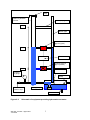
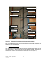
1
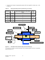
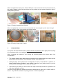
UHRIG KANALTECHNIK
ASSESSMENT OF THE UHRIG KANALTECHNIK
QUICK LOCK LOCAL REPAIR SYSTEM
WRc Ref: UC7982
June 2009
ASSESSMENT OF THE UHRIG KANALTECHNIK QUICK LOCK
LOCAL REPAIR SYSTEM
Report:
UC7982
Date:
June 2009
Authors:
K Adams and A T Russell
Contract Manager: A T Russell
Contract No.:
15042-0
RESTRICTION: This report has the following limited distribution:
External: Client
Internal: Authors
Any enquiries relating to this report should be referred to the authors at the following
address:
WRc Swindon, Frankland Road, Blagrove, Swindon, Wiltshire, SN5 8YF.
Telephone: + 44 (0) 1793 865000
Fax: + 44 (0) 1793 865001
Website: www.wrcplc.co.uk
The contents of this document are subject to copyright and all rights are reserved. No part of
this document may be reproduced, stored in a retrieval system or transmitted, in any form or
by any means electronic, mechanical, photocopying, recording or otherwise, without the prior
written consent of the copyright owner.
This document has been produced by WRc plc.
CONTENTS
1.
INTRODUCTION
1
1.1
1.2
Outline of system
The WRc Approved™ Scheme
1
1
2.
SUPPLIED THIRD PARTY AUDIT AND TESTING REPORTS
3
3.
MATERIAL PROPERTIES
5
3.1
3.2
3.3
Introduction
EPDM Rubber gasket
Steel Sleeve
5
5
5
4.
STRUCTURAL DESIGN
7
4.1
Structural design of the Quick Lock System
7
5.
FACTORY AUDIT
9
5.1
5.2
5.3
5.4
5.5
Background
Quality Assurance system
Rubber Gasket production
Steel Sleeve production
UHRIG Kanaltechnik checking of finished components
9
9
9
11
12
6.
LONG TERM HYDROSTATIC TESTING
15
7.
JETTING RESISTANCE TESTING
17
8.
INSTALLATION MANUAL
19
9.
SITE INSTALLATION AUDITS
21
9.1
9.2
9.3
Scope of audit
Audit criteria
Site audit Albbruck
21
21
22
10.
CONCLUSIONS
25
APPENDICES
APPENDIX A
APPENDIX B
APPENDIX C
QUICK LOCK ASSESSMENT SCHEDULE
QUICK LOCK LONG TERM HYDROSTATIC PERFORMANCE
TEST
QUICK LOCK LONG HIGH PRESSURE WATER JETTING
PERFORMANCE TEST
LIST OF FIGURES
Figure 5.1
Figure 5.2
Work station with table of tolerance requirement and examples of
gaskets defects
Finished goods storage at UHRIG Kanaltechnik
12
13
LIST OF TABLES
Table 2.1
Table 3.1
Daily hydrostatic pressure profile during ‘wet’ testing
Installation summary
4
11
1.
INTRODUCTION
1.1
Outline of system
The “Quick Lock” is a local repair system supplied by Uhrig Kanaltechnik GmbH of Geisingen
Germany. The system consists of two components that are assembled on site prior to
installation. An EPDM rubber gasket is pulled over a coiled steel sleeve which contains a unidirectional locking mechanism to form the Quick Lock Repair. The Quick Lock repair is
positioned in the pipe over the defect by using CCTV and an inflatable packer. Once in
position the packer is inflated thereby uncoiling the steel sleeve and engaging the locking
mechanism. The expansion of the steel sleeve compresses the rubber gasket between the
walls of the steel sleeve and host pipe. When the packer is deflated, the repair remains in
position as the locking mechanism is uni-directional.
The Quick Lock can be installed either as a single stand alone repair or in series when the
Quick Lock repairs are overlapped to form a continuous repair. The Quick Lock repair is
available in a range of diameters:
•
Diameter 150 mm-700 m in length of 400 mm lengths
•
Diameter 500 mm-800 m in length of 500 mm lengths
The Quick Lock is Approval is at present for use in foul and surface water drainage.
1.2
The WRc Approved™ Scheme
WRc Approved™ assesses the performance of a product as it relates to the application
defined by the manufacturer or supplier. The evaluation of the product is based upon an
Assessment Schedule that is prepared by WRc in conjunction with the manufacturer or
supplier of the product. Once a product has been approved and the certificate is issued, the
Assessment Schedule becomes a publicly available document.
The requirements of an Assessment Schedule typically include:
•
the description of the product/service and scope of the approval;
•
the tests used to assess the performance of the product/service;
•
an evaluation of the installation instructions including witnessing the use of the product onsite at two locations, and;
•
an audit of the quality control procedures used in the manufacture/operation of the system.
The Assessment Schedule for the Quick Lock System is included in Appendix A of this report.
WRc Ref: UC7982
June 2009
1
WRc Ref: UC7982
June 2009
2
2.
SUPPLIED THIRD PARTY AUDIT AND TESTING REPORTS
UHRIG Kanaltechnik GmbH supplied translated copies of third party audits and testing
undertaken of the Quick Lock system as a whole and its components. The documents
supplied were:
•
Deutches Insititut fur Bautechnik (DIBT): General Approval by the building authority’s
approval number Z-42.3.374 (Issue April 2005 valid until April 2010).
•
Fachhochschule Münster University of Applied Sciences; External pressure test on Quick
Lock Sleeves DN200 to DN600. (31 October 2008).
•
IRO Oldenburg GmbH: Jetting resistance test according to draft DIN Standard 19523
August 2007.
•
MPA Darmstadt Staatliche Materalprufungsanstalt Darmstadt- records of previous audits
undertaken by Winfred Lobig of Technische Universaitate Darmstadt.
WRc Ref: UC7982
June 2009
3
WRc Ref: UC7982
June 2009
4
3.
MATERIAL PROPERTIES
3.1
Introduction
The installed system consists of two the EPDM Rubber gasket and Steel Sleeve. As the
system is installation by mechanical bracing there are no additional chemicals products (e.g.
resins, glues).
3.2
EPDM Rubber gasket
The rubber gaskets are manufactures for materials that compile the German DIN Standards
listed below:
•
DIN 53504: Tensile strength, Elongation, modulus.
•
DIN 53505: Hardness.
•
DIN 53519: Compression.
•
DIN ISO 1183: Specific gravity.
•
DIN ISO 815: Compression set, stress relaxation.
DIN 53529 Rheometer Monsanto 200
3.3
Steel Sleeve
The Quick Lock system utilises V4A stainless steel which is suitable for use in wastewater
applications.
There are no structural requirements for the steel sleeve, refer to Section 4.1.
WRc Ref: UC7982
June 2009
5
WRc Ref: UC7982
June 2009
6
4.
STRUCTURAL DESIGN
4.1
Structural design of the Quick Lock System
Research undertaken by WRc in collaboration with a number of UK Water and Sewerage
Companies and manufacturers and suppliers of sewer repair systems has been undertaken in
our Underground Testing Facility. Loading trials have demonstrated that patch (local) repairs
do not have to be structurally designed. They do though have to be leaktight to ensure that
infiltration of groundwater will not occur as infiltrating water could potentially erode the ground
supporting the sewer and hence lead to collapse.
A suite of collaborative research projects have been undertaken which have resulted in a long
term (i.e. 6 month duration) hydrostatic test procedure which demonstrates the leak tightness
potential of sewer repairs to simulated variations in groundwater level. This procedure is
included within the following documents:
•
WIS 4-34-06 “Specification for localised sewer repairs using cured-in-place systems with
or without re-rounding”, November 2008: Issue 1.
•
Drain repair manual, 2nd Edition, WRc, 2005.
The Quick Lock system is currently undergoing WRc long term hydrostatic testing and the
results of this testing will be available during May 2009.
WRc Ref: UC7982
June 2009
7
WRc Ref: UC7982
June 2009
8
5.
FACTORY AUDIT
5.1
Background
Kevin Adams of WRc audited the manufacturing process of the Quick Lock system on 27th
and 28th January 2009. The production of the Quick Lock is undertaken in three stages by
three separate local companies under the control of Uhrig Kanaltechnik GmbH. The Uhrig
Kanaltechnik GmbH premises are primarily used for the storage of finished goods. For the
factory audit, four premises were visited for different stages of the manufacture and assembly
of the Quick Lock repair
•
Südbadische Gummiwerke GmbH : Manufacture of EPDM rubber gasket.
•
Gerstmaier Blechverabeitung GmbH: Cutting of tooth slot and preparation of steel sleeve
uncoiled.
•
Graf Feinmechanik GmbH: Fitting of locking mechanism and coiling of steel sleeve.
•
Uhrig Kanaltechnik GmbH : Storage of finished components.
5.2
Quality Assurance system
Uhrig Kanaltechnik GmbH operate an in-house Quality Assurance systems that monitors the
production procedure for the receipt of raw components to the finished lining ready for
despatch, inclusive of when the components are transferred between companies.
Uhrig Kanaltechnik GmbH does not hold ISO9001 certification.
The factory audit was undertaken concurrently with a quality audit undertaken by Technische
Universaitate Darmstadt. This external audit is undertaken twice every year and covers the
manufacturing process of Quick Lock Repair components. The audit for Staatliche
Materialprüfungsanstalt Darmstadt was undertaken by Winfred Löbig.
5.3
Rubber Gasket production
5.3.1
Specification requirement of rubber
The rubber gaskets are manufactured by Südbadische Gummiwerke GmbH to Uhrig
Kanaltechnik material and dimensional specifications.
The technical data sheet of the required material properties of the raw rubber material for the
manufacture of the gaskets was presented to WRc. This listed required vulcanised condition
of the rubber against current German standards, these include:
•
DIN 53504: Tensile strength, Elongation, modulus.
•
DIN 53505: Hardness.
WRc Ref: UC7982
June 2009
9
•
DIN 53519: Compression.
•
DIN ISO 1183: Specific gravity.
•
DIN ISO 815: Compression set, stress relaxation.
•
DIN 53529 Rheometer Monsanto 200 E.
5.3.2
Quality checks on receipt of rubber
Kraiburg GmbH & Co KG, Waldkraiburg are the suppliers to Südbadische Gummiwerke
GmbH of the rubber that is delivered in sheet format. Each batch delivery is accompanied by
a certificate of compliance from Kraiburg GmbH & Co KG as a requirement of the supplier
agreement. The certificate lists the tolerance of each parameter and the declared value of the
batch.
The batch is held in storage in a pending area until the declared material properties of the
batch are confirmed by in house testing. In house property checks include: hardness, density
and elasticity. Südbadische Gummiwerke GmbH provided historic records of the past in-house
testing of received goods. Deliveries passing the in-house checks are then brought into the
stock; any deliveries failing are rejected.
5.3.3
Production of gasket
The rubber sheets are cut into pieces and allocated by weight for each sleeve. The weight
required for the sleeve is dependent upon the diameters of the finished gasket. The shape
and size of the rubber pieces is not important to the manufacturing process other than all
pieces fitting in the gasket mould. The key factor is the total weight of the rubber pieces.
It was noted that the parameters of the weight of rubber for each of the gasket diameter sizes
was available to the machine operators.
The mould process is automated with the time and temperature set. When the gasket has
been produced it is removed from the mould and visually inspected of defects. The gasket is
allowed to cool and then manual stamped with a birth tag, for point and date of manufacture.
Südbadische Gummiwerke GmbH undertaken final in house quality checks a sample of
gasket’s properties for hardness, tensile strength, elongation and compression; physical
dimensions are also checked. Any gasket’s failing to meet the specification will be rejected
and further testing is undertaken on the appropriate production batch.
The gaskets are then transferred to Uhrig Kanaltechnik’s storage facilities.
WRc Ref: UC7982
June 2009
10
5.4
Steel Sleeve production
5.4.1
Purchase of steel
Uhrig Kanaltechnik GmbH Purchase the V4A steel sheets cut to shape from Outo Kumpu
(Finland). Visual inspection and dimensional checks are undertaken on the sheets before they
are transferred to Gerstmaier Blechverabeitung GmbH for the cutting of the toothed slot.
Uhrig Kanaltechnik GmbH has a customer agreement and quality specification for the steel
with Outo Kumpu.
5.4.2
Cutting of toothed slots
The steel sheets are received by Gerstmaier Blechverabeitung GmbH from Uhrig
Kanaltechnik GmbH storage and visually inspected prior to cutting. The cutting process is fully
automated and parameters are dependent upon the diameter of the Quick Lock repair.
Once the toothed slot has been cut, the sheet is cleared of burs and shavings and visually
inspected. A physical check on the cut slot is undertaken on the first, last and intermediate
(typically every 75) sheets from any batch to ensure the locking mechanism will fit and
function.
Gerstmaier Blechverabeitung GmbH have a “free standing” version of the 3 cog locking
mechanism which is used to physically ensure the toothed slots are cut within tolerance and
the lock will function as designed. As the locking mechanism used is free standing, it can
simply be disassembled and removed from the slot and reused in subsequent quality checks.
It was noted that the factory was tidy, goods clearly labelled and records of production
maintained
5.4.3
Fitting locks and coiling of cut steel sheets
The coiling of the sheets, manufacture and the fitting of the locks is undertaken by Graf
Feinmechanik GmbH at their workshop.
The technique of coiling the cut steel sheet is a guarded process. The process is semiautomated so that the coiled sleeve is less than the diameter of the intended pipe.
The cogs for the locking mechanism are manufactured by Graf Feinmechanik GmbH on site
by an automated cutting process from solid per cut cores of steel.
The fitting of the lock is a precise, intricate manual process. The cut slot is checked with a free
standing locking mechanism prior to the lock being fitted. The coiled sleeves with fitted locks
are then transferred to Uhrig Kanaltechnik for finished component storage.
It was noted for each of the machines used for the process, a method statement and the
product allowable parameters were readily available. The workshop was clean and tidy.
WRc Ref: UC7982
June 2009
11
5.5
Uhrig Kanaltechnik GmbH checking of finished components
5.5.1
Rubber gasket
The gaskets undergo testing for dimensional properties before becoming finished goods ready
for despatch to the installer.
The gasket is visually inspected; dimensions of the gaskets are checked to ensure that they
are within the tolerance of the specification. Measurements taken are:
•
Wall thickness.
•
Total length.
•
Height of circumferential sealing ribs/knobs.
•
Distance between the end of the gasket and circumferential sealing ribs/knobs.
•
Distance between the circumferential sealing ribs/knobs.
It was noted that a schematic with the tolerance was on display at the work station in the
finished good store. The work station also contained a display of cut outs for rejected seals as
an aid to what is not acceptable.
Staatliche Materialprüfungsanstalt Darmstadt conducted a visual inspection and dimensions
check on a randomly select gasket from storage. The gasket had no visible defects and all
measurements were found to be within tolerance of the specification for the diameter.
Figure 5.1
Work station with table of tolerance requirement and examples of gaskets
defects
WRc Ref: UC7982
June 2009
12
5.5.2
Steel sleeve
The sleeves entering Uhrig Kanaltechnik final goods store are subject to a visual inspection
and dimensional check. It is not possible to test the performance of the locking mechanism
with out sacrificing the sleeve since it is not possible to reverse the expanding action of the
lock.
Staatliche Materialprüfungsanstalt Darmstadt conducted a visual inspection and dimensions
check on a randomly select sleeve from storage. A 150 mm diameter steel sleeve was fully
expanded to check that the tolerances of the expanded sleeve were met. A 150 mm sleeve is
chosen as the sleeve is not usable once the lock has been fully open. The steel sleeve had no
visible defects and all measurements were found to be within tolerance of the specification for
the diameter. The locking mechanism performed within the specified tolerances.
5.5.3
Storage of finished components
WRc inspected the storage facilities and the following observations were made:
•
The storage area was tidy, laid out in an orderly manner with allotted storage space for
each component, based on diameter of the gasket or steel sleeve, to enable items to be
easily located.
•
All goods were clearly labelled.
Figure 5.2
Finished goods storage at Uhrig Kanaltechnik GmbH
WRc Ref: UC7982
June 2009
13
WRc Ref: UC7982
June 2009
14
6.
LONG TERM HYDROSTATIC TESTING
The objective of this project was to conduct the long-term external hydrostatic pressure test
on the Quick Lock localised repair system and determine whether the installed repair can
achieve an acceptable level of leak tightness.
All three Uhrig Quick Lock patch repairs passed the long-term external hydrostatic water
pressure (leaktightness) test carried out in accordance with the revised Appendix B of the
Specification for Local Sewer Repairs, Issue 2, 2005.
For all three installed repairs in was noted that there was evidence of infiltration approximately
2 hours after the pressure cycle had reached 5m head. However it was common occurrence
for the infiltration not to be sufficient to reach the each of the pipe before the applied pressure
was reduced from 5 m. There the measured infiltration is seen as minimal and only when 5 m
of external pressure applied.
Detail report has been included in Appendix B.
WRc Ref: UC7982
June 2009
15
WRc Ref: UC7982
June 2009
16
7.
JETTING RESISTANCE TESTING
The system has demonstrated that it passes the WIS requirement when high pressure jetting
is in accordance with your installation manual.
When reviewing the results of the testing the following points have been taken into
consideration:
•
The system passes when high pressure is applied to the tapered end of the repair (as the
jetting head is pulled back). The installation manual clearly states this.
•
Although jetting water passed the non-tapered end seal it was difficult to position our
jetting nozzle and we consider it very unlikely in practice for a jetting nozzle to get into
such a position and apply a force under the steel lip.
•
Please confirm that when the repairs are installed in series a non-tapered end and
tapered end abut. Is it possible that both ends of the assembly have a tapered end?
•
Also, would it be possible to modify the design for a 'single' repair so that it has tapered at
both ends? UHRIG may wish to consider this in future product development?
•
It should also be taken into account that the repair used had passed the hydrostatic test
with minor infiltration at 5 bar.
•
At present no other localised repairs have undertaken testing in accordance with WIS 435-0 and therefore WRc does not consider the above result means the Quick Lock
product cannot be WRc Approved - as the jetting operation which passed water was
undertaken in a manner that is not recommended in your installation manual.
The tapered site of the sleeve is always installed against the flow direction (see
installation manual). Since at least 95% of all cases the channels are cleaned in flow
direction, the tapered side is always against the water-jet.
Pressure testing undertaken to DIN 19523 (is existent), where the sleeves were tested on
high pressure jetting. The leak-test after the high pressure test has clearly shown, that
the Quick-Lock System was tight leaktight.
The Quick Lock was tested and met the requirement in clause 6.10 of WIS 4-35-01: Issue 1:
July 2000 for resistance to jetting pressure of 180 bar (2610 PSI).
A detailed report has been included in Appendix C.
WRc Ref: UC7982
June 2009
17
WRc Ref: UC7982
June 2009
18
8.
INSTALLATION MANUAL
A User Manual was submitted to WRc for a desk review. The manual had no version number
but was dated July 01 2008.
WRc forwarded a number of comments regarding the installation procedure; however it was
thought that most of the queries related to the translation of the instruction to English rather
than the process of installation and would become clearer upon witnessing an installation.
On 27th January 2009, WRc received an amended user manual (revision 1) dated
11/2008.This issue was used for the site audit in January 2009 in Albbruck Germany.
The User Manual was reviewed after the witnessed installation. It was concluded that most of
the issues relating the user manual related to terminology and translation. WRc would review
the English version based upon the witnessed installation and subsequent discussions. Key
points of the revisions were:
1. Format and control referencing of the document (version number, reference, issue date,
page numbering).
2. Translation and consistent terminology.
3. That only Uhrig Kanaltechnik GmbH own designed packer‘s should only be used for the
installation.
4. Concise details on when the repair is first placed over the defect and inflated to 2 bar; the
locking mechanism starting to engage so that the repair is tight in the host pipe without the
gasket being fully compressed. The packer is deflated and pulled back so that the packer
is centred in the Quick Lock repair. The packer is then inflated a second time to 2.5 to 3.5
bar to fully engage the lock and compress the gasket between the expanded steel sleeve
and host pipe This process would benefit from a schematic of the process rather than just
text.
WRc have assisted with the drafting of the installation instructions to address points 1 and 2.
The current manual is: Quick Log installation manual version 1 04/2009
WRc Ref: UC7982
June 2009
19
WRc Ref: UC7982
June 2009
20
9.
SITE INSTALLATION AUDITS
9.1
Scope of audit
The aim of the site audits is to ensure that the procedures within the Quick Lock User Manual
are comprehensive and that they can be followed throughout the witnessed installation
process. The approval requires two successful audited installations against the installation
manual.
Three Quick Lock repairs had been installed at WRc’s Underground Test Facility at Swindon
in November 2008 to be used for the long term hydrostatic testing of the repairs to ground
water resistance. These were witnessed against the July 2008 user manual and the
observations from these installations were included in the desk review comments.
It should be noted that installers of the Quick Lock system will have attended an Uhrig
Kanaltechnik GmbH training course on the installation of the Quick Lock System.
9.2
Audit criteria
All general safety aspects - such as working on highways, confined spaces, etc. - have been
excluded from the audit as the installer’s corporate safety policies should be in compliance
with national, local authority and additional client requirements. A brief statement to this effect
should be included in the installation manual to show that H & S has not been overlooked.
The assessment covers Quick Lock local repair system with or without the crimped upstream
edge installed either as a stand alone repair or in series to form a continuous repair length.
Variations to the system, including the use of hydrophilic seals or grouting of the gasket are
contained within the User Manual but not covered by the WRc Approval.
The use of hydrophilic seals and grouting the gasket is contained within the installation
manual to ensure that when installed they are done so in a consistent manner specified by
Uhrig Kanaltechnik GmbH by all of the trained contractors. However, the long term
performance of these variations is beyond the remit of the WRc Approval as neither variation
has yet been tested with regards to long term leaktightness and durability. Therefore these
variations of the system are not included the assessment and subsequent WRc Approval.
It should be noted that the Quick Lock repairs installed for the long term hydrostatic testing do
not contain hydrophilic seals and that the resistance to infiltration via the hydrostatic head is
solely for the compressed circumferential knobs/ribs of the gasket between the steel sleeve
and host pipe. The use of a hydrophilic seal is viewed as an additional means of infiltration
prevention to the circumferential knobs/ribs on the gasket
WRc did not witness the original data collection process undertaken to determine the defects
within the pipe or any of the enabling work on the host pipe such as high pressure jetting,
milling of intruding laterals. The audits focused on the installation of the lining, starting from
the delivery of the lining on site.
WRc Ref: UC7982
June 2009
21
9.3
Site audit Albbruck
9.3.1
Site details
On 28th January 2009 Kevin Adams (WRc) witnessed the installation of four Quick Lock local
repairs at Albbruck Germany. The installations were undertaken by Uhrig Kanaltechnik
GmbH’s own installation team.
The repairs were installed in a 500 mm diameter concrete pipe which took waste water from a
paper production factory. The pipe was located in a surfaced area that would be subject to
road loadings and was approximately 3 m in depth. Four defects had been identified:
•
At 3 m circumferential crack;
•
At 6 m circumferential crack;
•
At 33 m calcium deposits / corrosion of pipe wall;
•
At 35 m displaced joint.
9.3.2
Pre-installation activities
WRc did not witness the prerequisite activity of clearing the host pipe by high pressure jetting;
however WRc did witness the pre-installation CCTV to confirm the type and position of the
defects.
WRc would recommend the installation manual is updated to state that the entire length the
host pipe is clear of any debris or substance which could impact on the performance of the
repair. This not only includes any within the vicinity of the defect but also sound sections of
pipe which the repair / packer will travel through as well as up-stream to the next access point.
9.3.3
Installation manual section 2: Equipment/ Materials
WRc would recommend revision of the user manual with a breakdown of:
•
Quick Lock components and variations (items that remain in the pipe);
•
Equipment and consumables for installation.
9.3.4
Installation of the Quick Log Repair
All the installations witnessed were completed following the Installation Manual. The
installations witnessed were all single Quick Lock repairs. WRc was supplied with a copy of
the installation report which contains details of the position of the repairs as well photographs
of the defects and installed repair.
It is seen as good practice when more than one “single” installation is to be installed in a pipe
section that the furthest from the access point is repaired first, working back towards the
access point. Whilst this is regarded as good practice, it was demonstrated that it is possible
WRc Ref: UC7982
June 2009
22
for a semi inflated packer (loaded with a Quick Lock Repair) to pass through a previously
installed repair. This ability should be included in the report.
The installation instructions have been broken down into stages, however the translation
needs to be refined:
•
Preparation of the Quick Lock sleeve.
•
Position of the Quick Lock sleeve on the packer.
•
Setting the packer for the host pipe diameter.
•
Positioning and installing the repair over the defect.
•
Installing Quick Lock repairs in series.
•
Removal of installed Quick Lock repairs.
•
Variations.
WRc Ref: UC7982
June 2009
23
WRc Ref: UC7982
June 2009
24
10.
CONCLUSIONS
Uhrig Kanaltechnik GmbH Quick Lock local repair system has successfully undertaken all
aspects specified within the Assessment Schedule and has been awarded WRc Approved ™
certification detailed below.
PT/283/0609: Uhrig Kanaltechnik GmbH Quick Lock local repair system for diameter range
150 mm -700 mm diameter in 400 mm or 500 mm lengths; Assessment schedule
AS/283/0609
All certificates are valid for 5 years from the issue date.
WRc Ref: UC7982
June 2009
25
WRc Ref: UC7982
June 2009
26
APPENDIX A
QUICK LOCK ASSESSMENT SCHEDULE
WRc Ref: UC7982 – Appendix A
June 2009
WRc Ref: UC7982 – Appendix A
June 2009
WRc Ref: UC7982 – Appendix A
June 2009
WRc Ref: UC7982 – Appendix A
June 2009
WRc Ref: UC7982 – Appendix A
June 2009
WRc Ref: UC7982 – Appendix A
June 2009
APPENDIX B
QUICK LOCK LONG TERM HYDROSTATIC
PERFORMANCE TEST
WRc Ref: UC7982 – Appendix B
June 2009
WRc Ref: UC7982 – Appendix B
June 2009
CONTENTS
1.
INTRODUCTION
1
1.1
1.2
1.3
Background
Objective
Resume of Contents
1
1
1
2.
TEST PROCEDURE
3
2.1
2.2
2.3
2.4
Long term testing of localised repairs
Long-term hydrostatic test regime
Infiltration measurement
Pass/fail criteria
3
3
8
9
3.
REPAIR INSTALLATION
11
3.1
3.2
Quick Lock local repair installations
Setting up the repairs for hydrostatic testing
11
12
4.
TEST RESULTS
13
4.1
4.2
4.3
4.4
Test observations
First wet cycle infiltration graphs
Second wet cycle infiltration graphs
Third wet cycle infiltration graphs
13
13
15
16
5.
CONCLUSIONS
19
WRc Ref: UC7982 – Appendix B
June 2009
LIST OF TABLES
Table 2.1
Daily hydrostatic pressure profile during ‘wet’ testing
4
LIST OF FIGURES
Figure 2.1
Figure 2.2
Figure 2.3
Figure 3.1
Figure 4.1
Figure 4.2
Figure 4.3
Figure 4.4
Figure 4.5
Figure 4.6
Figure 4.7
Figure 4.8
Figure 4.9
Schematic of the localised repair pressure testing rig
Schematic of equipment providing hydrostatic test water
Photograph of equipment providing hydrostatic test water
Installation summary
Infiltration rate for repair 1 - first wet cycle
Infiltration rate for repair 2 - first wet cycle
Infiltration rate for repair 3 - first wet cycle
Infiltration rate for repair 1 - second wet cycle
Infiltration rate for repair 2 - second wet cycle
Infiltration rate for repair 3 - second wet cycle
Infiltration rate for repair 1 - third wet cycle
Infiltration rate for repair 2 - third wet cycle
Infiltration rate for repair 3 - third wet cycle
WRc Ref: UC7982 – Appendix B
June 2009
4
7
8
12
13
14
14
15
15
16
16
17
17
1.
INTRODUCTION
1.1
Background
WRc’s Portfolio project CP167 “long term testing of sewer repair and sealing techniques”
(2004) developed a long-term external hydrostatic test and the hydrostatic test specified in
Appendix C of the Specification for Local Sewer Repairs has been updated to include this
test.
The revised Specification for Local Sewer Repairs has been submitted to Water UK for
consideration to become a full Water Industry Specification (WIS).
1.2
Objective
The objective of this project was to conduct the long-term external hydrostatic pressure test
on the Quick Lock localised repair system and determine whether the installed repair can
achieve an acceptable level of leak tightness.
1.3
Resume of Contents
•
Section 2 presents details of the long-term hydrostatic testing procedure.
•
Section 3 describes the repairs that were conducted for subsequent testing.
•
Section 4 presents the long-term hydrostatic testing results.
•
Section 5 lists the conclusions from the tests.
WRc Ref: UC7982 – Appendix B
June 2009
1
WRc Ref: UC7982 – Appendix B
June 2009
2
2.
TEST PROCEDURE
2.1
Long term testing of localised repairs
2.1.1
Objective
Three localised repairs were exposed to a cyclic varying hydrostatic pressure and the extent
of infiltration was measured.
2.1.2
Test rigs
The ‘Specification for Local Sewer Repairs’ states:
•
repairs will be undertaken in DN 300 clay pipes;
•
each pipe will have a defect (100x100 mm hole) cut at the centre of the pipe;
•
the defect will be positioned at the springing during repair (a ‘resin pool’ may form if the
defect is positioned at or near the crown during repair);
•
each hydrostatic test rig consists of a fabricated steel tube with adaptors bolted to each
end that form a seal on the host pipe when tightened. Figure 2.1 depicts a schematic of a
localised repair pressure testing rig;
•
inlet and outlet valves on the hydrostatic test rigs enables water to be pumped into the
annulus between the pipe and steel tube;
•
each patch repair will be 1 m long, and;
•
two repairs will be undertaken with no hydrostatic head of water and one will be
undertaken against a 2 m hydrostatic head of water.
2.2
Long-term hydrostatic test regime
2.2.1
Testing requirements
The ‘Specification for Local Sewer Repairs’ states that:
•
long term pressure testing will be at a maximum hydrostatic pressure of 5 m;
•
the hydrostatic testing will be undertaken over a 6 month period. This will consist of
1 month under cyclic pressure (i.e. ‘wet’), 1 month with no hydrostatic pressure and all
valves left open (i.e. ‘damp’), 1 month ‘wet’, 2 months ‘damp’ and 1 month ‘wet’. This
wet/damp cycle is intended to simulate the seasonal changes in ground water level, and;
WRc Ref: UC7982 – Appendix B
June 2009
3
•
during the ‘wet’ testing, the hydrostatic pressure will be the applied in a daily cycle – refer
to Table 2.1.
Table 2.1
Daily hydrostatic pressure profile during ‘wet’ testing
Start time
To
Approximate duration to reach head
(mins)
Head
(m)
00.00
9.00
-
1
9.00
9.02
2
2.5
9.58
10.00
5
5
16.00
16.01
1
2.5
17.00
17.01
1
1
Pressure gauge
100 X 100mm defect
Air vent
Local repair
Gasket
Max adaptor
Infiltration route
Rain gauge &
logger
Clay pipe
Pressure source from hydrostatic
Figure 2.1
Schematic of the localised repair pressure testing rig
The equipment needed to provide test water at the required pressure and time is described
below in section 2.2.2.
WRc Ref: UC7982 – Appendix B
June 2009
4
2.2.2
Hydrostatic test column
The test column consists of a submersible pump, two motorised valves (T1 and T2 in
Figure 2.2); a two channel, 24 hour, seven day timer, two 125l header tanks and a 6 m vertical
length of 6” (150 mm) PVC pipe with tappings at 1 m, 2.5 m and 5 m.
2.2.3
Water reservoir
The two header tanks are coupled together to form a 250l water reservoir (when the column is
drained down or on the lower 1 m setting).
2.2.4
Submersible pump
The submersible pump pumps water through a 1” (25.4 mm) ‘L’ port drain down / diverter
valve from the reservoir to the bottom of the test column. The water returns to the reservoir
from various heights on the column controlled by the timer.
2.2.5
Timer
The timer controls two 1” (25.4 mm) motorised ball valves mounted on the column to give a
hydrostatic pressure to the test samples of 1 m, 2.5 m and 5 m.
The timer is programmed to alter the hydrostatic pressure daily as shown in Table 2.1.
2.2.6
Hydrostatic column
The vertical 6 m hydrostatic column has the following connections:
•
a 1/4” (6.35 mm) connection at the bottom for the test samples, complete with isolating
valve and pressure gauge.
•
a 1” (25.4 mm) ‘L’ port valve just above the test sample connection, which is
connected to the submersible pump.
•
The first 1” (25.4 mm) ball valve is mounted at 1 m, the outlet of which is connected to
a 1” (25.4 mm) common reservoir return pipe.
•
the other 1” (25.4 mm) ball valve is mounted at 2.5 m; this is also connected to the
return pipe.
•
at 5 m an overflow connection is connected to the return pipe.
•
the top of the 6 m column is left open to the atmosphere.
•
if the first ball valve is open, the water is maintained at 1 m within the column.
•
if the first ball valve is closed and the second one open, the water is maintained at
2.5 m within the column.
WRc Ref: UC7982 – Appendix B
June 2009
5
•
if both ball valves are closed, the water is maintained at 5 m within the column.
•
there is a calibrated pressure gauge at the bottom of the hydrostatic column, at a
similar level to the outlet, which provides a visual readout of the water level within the
column.
•
the outlet has an isolation valve fitted.
WRc Ref: UC7982 – Appendix B
June 2009
6
Cap
150mm hydrostatic
column
Return pipe @ 5m
5m
Return pipe
Control valve T1
@2.5m (open)
2.5m
Timer
Control valve T2
@1m (closed)
1m
Reservoir
Pressur
e gauge
Water
Pressure
outlet to rigs
Sump pump
Drain valve
Figure 2.2
Schematic of equipment providing hydrostatic test water
WRc Ref: UC7982 – Appendix B
June 2009
7
Hydrostatic column to vent
Hydrostatic column
5m cross connection
Return pipe to reservoir
2.5m cross connection
pipe and control valve
1m cross connection
pipe and control valve
Pumped water
supply to column
Timer
Reservoir containing
sump pump
Pressure gauge
Pressure outlet to
sample
Test samples
Figure 2.3
Photograph of equipment providing hydrostatic test water
Note: the rain gauges at the lower end of the test pieces are not shown; the test samples are
not the Quick Lock test installations
2.3
Infiltration measurement
After the repairs had been installed and were ready for hydrostatic testing, all the test rigs
were tipped forward so that the lower pipe ends were adjacent and at the same level. Any
infiltrating water could then be collected from the lowest pipe ends (see Figure 2.3).
WRc Ref: UC7982 – Appendix B
June 2009
8
A tipping bucket rain gauge was placed under each of the repaired pipes so that any
infiltrating water would be collected and logged by the rain gauge and data logger.
Periodically, 100 ml of water was tipped into the rain gauges so that a ‘calibration spike’
appeared on the infiltration graphs. This was particularly useful for repairs where little or no
infiltration occurred as it showed that the logger was still working. Note: The reported
infiltration units are ml per hour; therefore 100 ml in a 30 minute time period would be
displayed as 200 ml per hour on the result graphs.
2.4
Pass/fail criteria
The ‘Specification for Local Sewer Repairs’ states that the infiltration limit rate is taken as that
detailed in Sewers for Adoption 5th Edition (WRc, 2001) (i.e. 500 ml/m diameter/m length at
5 m hydrostatic pressure over a 30 minute period), which is based upon BS EN 1610.
For localised repair testing, the internal diameter of the clay pipe is 0.3 m and Section 13 of
BS EN 1610 states that the repair length should be taken as 1 m. The infiltration limit is
therefore 150 ml per 30 minute period, hence 300 ml/hour.
WRc Ref: UC7982 – Appendix B
June 2009
9
WRc Ref: UC7982 – Appendix B
June 2009
10
3.
REPAIR INSTALLATION
3.1
Quick Lock local repair installations
Three Quick Lock local repairs where installed in the 300mm diameter clay pipes containing a
100 mm by 100 mm defect that had been installed in the hydro static rigs at WRc on Tuesday
18th November 2008 at WRc’s Underground Testing Facility. The installed Quick Lock
localised repairs were for long term hydro static testing as a part of the WRc Approval of the
system.
The installations were undertaken by Andrea Schulz (UHRIG) and Brian Hickland (McAllister
Brothers). The installation where witnessed by Andy Russell and Kevin Adams, both of WRc.
Repairs 1 and 2 were completed dry with no hydrostatic head of water applied to the test
pieces. The 100 mm by 100 mm defect located at the 3 o’clock position.
Repair 3 was conducted under pressure. The defect was located at the pipe springing as with
repairs 1 and 2. The rig was connected to the hydrostatic column which was set at 2.5 m/h via
the inlet valve on the underside of the hydrostatic test rig. Water from the column entered the
bottom of the hydrostatic rig via a valve with the valve located at the top of the rig open. The
lower valve was throttled back so a flow rate of approximately 1l per minute was infiltrating
into the clay pipe via the defect. When the repair was installed, the water was forced out of the
top vent valve. When water flowed from the vent pipe the valve on the pipe was closed by
placing the packer and sleeve under 2.5 m external water pressure.
The installation where undertaken in accordance with the Quick Lock User Manual version
July 01 2005 with the following exception:
•
No glue was used between the EPDM rubber sleeve and steel sleeve due to the short
distance between the installation point and defect.
Table 3.1
Installation summary
Ref
Installation
condition
(mh)
Time
taken (m)
Packer
pressure
(b)
1
0
20
3.5
2
0
15
3.5
3
2.5
25
3.6
Observations
All three rigs were subject to the maximum test pressure of 5m within one hour of installation
in the presence of Andrea Schulz (UHRIG) and Brian Hickland (McAllister Brothers).
WRc were satisfied that the installations completed for the test were representative of the
product. Figures 3.1 to 3.5 show the key stages in the installation process.
WRc Ref: UC7982 – Appendix B
June 2009
11
1. Insertion of repair on
packer
2. Positioning of repair over
defect
3. Pressuring of repair to
engage locking mechanism
4.
5. Infiltration before
installation of Quick Lock
6
Checking position of
repair in non-pressurised
installation
Figure 3.1
3.2
Sealing of infiltration when
the packer is inflated and
engaging locking
mechanism
Installation summary
Setting up the repairs for hydrostatic testing
On 23rd November 2008, the repaired pipes were filled with water via a 12 mm plastic pipe
from the hydrostatic column to the test rigs. Each test rig was supplied a spur off this main
supply pipe fed each test rig via an isolation valve. The column pressure was set manually at
1m. Each test rig was filled via a valve at the invert of each rig, there by displacing all air
within the test rig. When all the air had been displaced and water spilled from the top valve,
the top valve was closed thereby pressurising the test rig.
The hydrostatic column was kept at a 1 m head to allow the test pieces to stabilise. The cyclic
pressure regime was programmed to start at 00.00 on 24th November 2008, with the first
pressure change at 9:00 (refer to Table 2.1).
WRc Ref: UC7982 – Appendix B
June 2009
12
4.
TEST RESULTS
4.1
Test observations
For all three wet cycles, no infiltration was measured or observed at any of the tests.
Any infiltration is measured by the rain gauge as a tip of the bucket and the data logger
records each tip of the bucket as an event. With a bucket of known volume, the numbers of
events and time of each event allowed an infiltration rate to be calculated. There had been no
infiltration during the test cycle, there logger had no events to log. As proof that the logger was
recording throughout the test period WRc triggered events with known volumes (100 ml)
which appear as spikes on the graphs are accountable.
The infiltration and ‘calibration spike’ volumes were measured and logged in 30 minute time
periods. The infiltration graph below shows the volume of infiltration in ml/hour and hence
infiltration rates and ‘calibration spike’ columns have been doubled to 200 ml and 300 ml per
hour.
For all the wet cycles, all three repairs showed no sign of any infiltration. The plots for each rig
for each wet cycle can be seen in Figures 4.1 to 4.9.
4.2
First wet cycle infiltration graphs
Uhrig Repair 1 First Wet Cycle 23th November to 22nd December 2008
350
300
Inflitration mm/hour
250
200
Volume (ml/hour)
BS EN 1610 limit
150
100
50
24
/1
25 1/2
/1 00
8
26 1/2
/1 00
8
1
/
27 2
/1 00
8
28 1/2
/1 00
8
29 1/2
/1 00
8
1
30 /2
/1 00
8
01 1/2
/1 00
8
2
02 /20
/1 0
8
2
03 /2
/1 00
8
04 2/2
/1 008
2
/
05 2
/1 00
8
06 2/2
/1 00
8
07 2/20
/1 0
8
08 2/2
/1 00
8
09 2/2
/1 008
2
10 /2
/1 00
8
11 2/2
/1 00
8
2
12 /2
/1 00
8
2
13 /2
/1 00
8
14 2/2
/1 008
15 2/2
/1 00
8
16 2/2
/1 00
8
2
17 /2
/1 00
8
2
18 /2
/1 00
8
19 2/2
/1 00
8
2
20 /2
/1 00
8
21 2/2
/1 00
8
2
22 /2
/1 00
2/ 8
20
08
0
Time
Figure 4.1
Infiltration rate for repair 1 - first wet cycle
WRc Ref: UC7982 – Appendix B
June 2009
13
24
/1
25 1/2
/1 00
8
26 1/2
/1 00
8
1
/
27 2
/1 00
8
28 1/2
/1 00
8
29 1/2
/1 00
8
1
30 /2
/1 00
8
01 1/2
/1 00
8
2
02 /20
/1 0
8
2
03 /2
/1 00
8
04 2/2
/1 008
2
/
05 2
/1 00
8
06 2/2
/1 00
8
07 2/20
/1 0
8
08 2/2
/1 00
8
09 2/2
/1 008
2
10 /2
/1 00
8
11 2/2
/1 00
8
2
12 /2
/1 00
8
2
13 /2
/1 00
8
14 2/2
/1 008
15 2/2
/1 00
8
16 2/2
/1 00
8
2
17 /2
/1 00
8
2
18 /2
/1 00
8
19 2/2
/1 00
8
2
20 /2
/1 00
8
21 2/2
/1 00
8
2
22 /2
/1 00
2/ 8
20
08
Inflitration mm/hour
Uhrig Repair 2 First Wet Cycle 23rd November to 22nd December 2008
350
300
250
200
Volume (ml/hour)
BS EN 1610 limit
150
100
50
0
Time
Figure 4.2
Figure 4.3
Infiltration rate for repair 2 - first wet cycle
Uhrig Repair 3 First Wet Cycle 23rd November to 22nd December 2008
350
300
250
200
Volume (ml/hour)
BS EN 1610 limit
150
100
50
0
Time
Infiltration rate for repair 3 - first wet cycle
WRc Ref: UC7982 – Appendix B
June 2009
14
Figure 4.5
WRc Ref: UC7982 – Appendix B
June 2009
15
Time
Infiltration rate for repair 2 - second wet cycle
19/02/2009
18/02/2009
17/02/2009
16/02/2009
15/02/2009
14/02/2009
13/02/2009
12/02/2009
11/02/2009
10/02/2009
09/02/2009
08/02/2009
07/02/2009
06/02/2009
05/02/2009
04/02/2009
03/02/2009
02/02/2009
01/02/2009
31/01/2009
30/01/2009
29/01/2009
28/01/2009
27/01/2009
26/01/2009
25/01/2009
24/01/2009
23/01/2009
22/01/2009
Figure 4.4
21/01/2009
20/01/2009
19/01/2009
Infiltration mm/hour
150
100
50
0
19/02/2009
18/02/2009
17/02/2009
16/02/2009
15/02/2009
14/02/2009
13/02/2009
12/02/2009
11/02/2009
10/02/2009
09/02/2009
08/02/2009
07/02/2009
06/02/2009
05/02/2009
04/02/2009
03/02/2009
02/02/2009
01/02/2009
31/01/2009
30/01/2009
29/01/2009
28/01/2009
27/01/2009
26/01/2009
25/01/2009
24/01/2009
23/01/2009
22/01/2009
21/01/2009
20/01/2009
19/01/2009
Infiltration ml/hour
4.3
Second wet cycle infiltration graphs
Uhrig Quick Lock repair 1 Second Wet Cycle 19th January to 17th February 2009
350
300
250
200
Volume (ml/hour)
BS EN 1610 limit
150
100
50
0
Time
Infiltration rate for repair 1 - second wet cycle
Uhrig Quick Lock repair 2 Second Wet Cycle 19th January to 17th February 2009
350
300
250
200
Volume (ml/hour)
BS EN 1610 limit
16
/0
4
17 /09
/0
4/
18 09
/0
4
19 /09
/0
4
20 /09
/0
4
21 /09
/0
4
22 /09
/0
4
23 /09
/0
4
24 /09
/0
4
25 /09
/0
4/
26 09
/0
4
27 /09
/0
4/
28 09
/0
4
29 /09
/0
4
30 /09
/0
4/
01 09
/0
5
02 /09
/0
5/
03 09
/0
5
04 /09
/0
5
05 /09
/0
5
06 /09
/0
5
07 /09
/0
5
08 /09
/0
5/
09 09
/0
5
10 /09
/0
5/
11 09
/0
5
12 /09
/0
5/
13 09
/0
5
14 /09
/0
5/
09
Infiltration ml per hour
Figure 4.6
4.4
Figure 4.7
WRc Ref: UC7982 – Appendix B
June 2009
16
Date
Infiltration rate for repair 1 - third wet cycle
150
100
50
0
19/02/2009
18/02/2009
17/02/2009
16/02/2009
15/02/2009
14/02/2009
13/02/2009
12/02/2009
11/02/2009
10/02/2009
09/02/2009
08/02/2009
07/02/2009
06/02/2009
05/02/2009
04/02/2009
03/02/2009
02/02/2009
01/02/2009
31/01/2009
30/01/2009
29/01/2009
28/01/2009
27/01/2009
26/01/2009
25/01/2009
24/01/2009
23/01/2009
22/01/2009
21/01/2009
20/01/2009
19/01/2009
Infiltration mm/hour
Uhrig Quick Lock repair 3 Second Wet Cycle 19th January to 17th February 2009
350
300
250
200
Volume (ml/hour)
BS EN 1610 limit
150
100
50
0
Time
Infiltration rate for repair 3 - second wet cycle
Third wet cycle infiltration graphs
Repair 1 third wet cycle (16 April to 15 May 2009)
350
300
250
200
Volume (ml/hour)
BS EN 1610 limit
Repair 2 third wet cycle (16 April to 15 May 2009)
350
300
Infiltration ml per hour
250
200
Volume (ml/hour)
BS EN 1610 limit
150
100
50
16
/0
4
17 /09
/0
4/
18 09
/0
4
19 /09
/0
4
20 /09
/0
4
21 /09
/0
4
22 /09
/0
4
23 /09
/0
4
24 /09
/0
4
25 /09
/0
4/
26 09
/0
4
27 /09
/0
4/
28 09
/0
4
29 /09
/0
4
30 /09
/0
4/
01 09
/0
5
02 /09
/0
5/
03 09
/0
5
04 /09
/0
5
05 /09
/0
5
06 /09
/0
5
07 /09
/0
5
08 /09
/0
5/
09 09
/0
5
10 /09
/0
5/
11 09
/0
5
12 /09
/0
5/
13 09
/0
5
14 /09
/0
5/
09
0
Date
Figure 4.8
Infiltration rate for repair 2 - third wet cycle
Repair 3 third wet cycle (16 April to 15 May 2009)
350
300
Infiltration ml per hour
250
200
Volume (ml/hour)
BS EN 1610 limit
150
100
50
0
09 09 09 09 09 09 09 09 09 09 09 09 09 09 09 09 09 09 09 09 09 09 09 09 09 09 09 09 09
4/ 4/ 4/ 4/ 4 / 4 / 4 / 4/ 4/ 4/ 4/ 4/ 4/ 4/ 4/ 5/ 5/ 5/ 5/ 5/ 5/ 5/ 5/ 5/ 5 / 5 / 5 / 5/ 5/
/0 /0 /0 /0 /0 /0 /0 /0 /0 /0 /0 /0 /0 /0 /0 /0 /0 /0 /0 /0 /0 /0 /0 /0 /0 /0 /0 /0 /0
16 17 18 19 20 21 22 23 24 25 26 27 28 29 30 01 02 03 04 05 06 07 08 09 10 11 12 13 14
Date
Figure 4.9
Infiltration rate for repair 3 - third wet cycle
WRc Ref: UC7982 – Appendix B
June 2009
17
WRc Ref: UC7982 – Appendix B
June 2009
18
5.
CONCLUSIONS
All three Uhrig Quick Lock patch repairs passed the long-term external hydrostatic water
pressure (leaktightness) test carried out in accordance with the revised Appendix B of the
Specification for Local Sewer Repairs, Issue 2, 2005.
For all three installed repairs in was noted that there was evidence of infiltration approximately
2 hours after the pressure cycle had reached 5 m head. However it was common occurrence
for the infiltration not to be sufficient to reach the each of the pipe before the applied pressure
was reduced down from 5m. Therefore not infiltration was measured.
WRc Ref: UC7982 – Appendix B
June 2009
19
WRc Ref: UC7982 – Appendix B
June 2009
20
APPENDIX C
QUICK LOCK LONG HIGH PRESSURE WATER
JETTING PERFORMANCE TEST
WRc Ref: UC7982 – Appendix C
June 2009
WRc Ref: UC7982 – Appendix C
June 2009
Test Report
CUSTOMER:
Uhrig Kanaltechnik GmbH.
PRODUCT
Quick Lock localised repair
TEST DATE:
May 2009
SPECIFICATION:
WIS 4-35-01: July 2000
REQUIREMENT:
The jetting resistance of the installed repair is to be established.
Resistance is the pressure that can be applied without damage as
defined in clause 6.10 of WIS 4-35-01: July 2000.
TEST METHOD:
As detailed in WIS 4-35-01 Appendix C
1.
INTRODUCTION
As a requirement for the WRc Approval™ of Uhrig Kanaltechnik GmbH. Quick Lock localised
repair system the system was tested for its resistance capability to withstand high-pressure
water jetting test in accordance with WIS 4-35-01: July 2000.
The testing was undertaken on repair 3 that had completed the long term hydrostatic testing
as reported in Appendix B. The test would determine whether the jetting nozzle could be
directly applied to the perceived weakness point of the rubber gasket underneath
The repair was tested to check it meets the requirements of WIS 4-35-01 and also to
determine the maximum pressure at which the pipe will pass the WIS 4-35-01 test procedure.
Clause 6.10 of WIS 4-35-01: July 2000 states that the “pipe” shall withstand a jetting pressure
of 180 bar (2600 psi) without defined unacceptable damage. It is therefore reasonable to
expect any repair to meet the jetting resistance of a new pipe. Appendix C of WIS 4-35-01
provides the test method and requirement for assessing the resistance of structured wall
pipes to pressure jetting. The jetting resistance of a material is defined as the maximum
pressure at which five consecutive successful 120 second duration tests are achieved.
Unacceptable damage is defined in WIS 4-35-01: July 2000 Clause B4.7 Note B as a
puncture or crack of the wall for a solid wall or multi-layer pipe where all the layers are of a
solid construction. Ductile bending or “whitening” is not considered to be damage.
WRc Ref: UC7982 – Appendix C
June 2009
2.
EQUIPMENT
The following equipment was used:
3.
•
A single jet nozzle (marked WRc 06) manufactured to the dimensions given in Figure
C.1 of WIS 4-35-01: July 2000.
•
Calibrated pressure gauge (PG1/PG56.)
•
A commercial Flexian Hawk trailer-jetting unit, fitted with a Spec piston pump capable
of a maximum pressure of 414 bar (6000 psi) pressure and capable of a flow rate of 36
litres per minute.
•
Test rig capable of operating at a maximum pressure of 350 bar (5000 psi).
TEST PIECES
Uhrig Kanaltechnik GmbH had undertaken three Quick lock Installations to supply test
samples for the long term hydrostatic tests. On completion of the hydrostatic test repair three
was selected for the high pressure jetting testing. The host clay pipe was cut back to provide
access to the interface of the host pipe and repairs.
The repair was tested at both end of the repair reference as the tapered end where the steel
sleeve tapers to the host pipe wall and the open end where the rubber seal is located under a
25mm overlap of the steel sleeve. The open cut from the defect was placed at the 12 o’clock
position and the annulus between repair and host pipe filled with water. Therefore any water
entering the annulus via the seal would displace the water in the annulus.
4.
RESULTS
Testing was undertaken by Kevin Adams and Huw William of WRc. The water temperature for
the test was 12.5oC and the ambient air temperature was 11.5oC. A summary of the test
pressures for 5 consecutive successful tests for each pipe diameter can be found in the table
below.
Test piece /
segment no.
Test piece /
segment no.
Test pressure
(bar / psi)
Repair 3/1
Tapered end
180 / 2600
No evidence of water passing the seal
Repair 3/2
Tapered end
180 / 2600
No evidence of water passing the seal
Repair 3/3
Tapered end
180 / 2600
No evidence of water passing the seal
Repair 3/4
Tapered end
180 / 2600
No evidence of water passing the seal
Repair 3/5
Tapered end
180 / 2600
No evidence of water passing the seal
Repair 3/1
Open end
180 / 2600
Water in annulus displaced after 20
seconds
WRc Ref: UC7982 – Appendix C
June 2009
Comments/type of failure
When we applied the water jet at 180 bar/2600 psi on the end of the Quick Lock sleeve where
the steel is tapered to the host pipe there was no problem as the system showed no sign of
water passing the seal
Figure 1 Testing of tapered end of repair
When we applied the same test to the non-tapered end we managed to push water through
the seal so that it exited via the defect see photos below:
Figure 2 Testing of open end of repair
5.
CONCLUSIONS
The system has demonstrated that it passes the WIS requirement when high pressure jetting
is in accordance with your installation manual.
When reviewing the results of the testing the following points have been taken into
consideration:
•
The system passes when high pressure is applied to the tapered end of the repair (as the
jetting head is pulled back). The installation manual clearly states this.
•
Although jetting water passed the non-tapered end seal it was difficult to position our
jetting nozzle and we consider it very unlikely in practice for a jetting nozzle to get into
such a position and apply a force under the steel lip.
•
It should also be taken into account that the repair used had passed the hydrostatic test
with minor infiltration at 5 bar.
The Quick Lock repair was tested and met the requirement in clause 6.10 of WIS 4-35-01:
Issue 1: July 2000 for resistance to jetting pressure of 180 bar (2600 psi).
WRc Ref: UC7982 – Appendix C
June 2009


![[Manual Makeup] - inverter & Plc](http://vs1.manualzilla.com/store/data/005906079_1-ccf407c70ed6dc9ae9bfcbd31676317c-150x150.png)