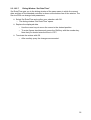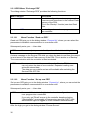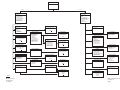
1
Industrial Automation
System HIMatrix
Service-PDA
User Manual
HIMA Paul Hildebrandt GmbH + Co KG
Industrial Automation
HI 800 049 CEA
Important Notes
All HIMA products mentioned in this manual are protected under the HIMA trademark. Unless not explicitly noted, this may apply for other referenced manufacturers
and their respective products.
All technical statements and data in this manual have been written with great care
and effective quality measures have been taken to ensure their validity; however this
manual may contain flaws or typesetting errors.
For this reason, HIMA does not offer any warranties nor assume legal responsibility
nor any liability for possible consequences of any errors in this manual. HIMA appreciates any correspondence noting potential errors.
Technical modifications reserved.
For more information see the documentation on CD-ROM and on our
web site www.hima.com .
More information can be requested from:
HIMA Paul Hildebrandt GmbH + Co KG
Postfach 1261
68777 Brühl
Tel: +49(6202)709 0
Fax: +49(6202)709 107
e-mail: [email protected]
Table of Contents
Description
1
1.1
Introduction
1
1.2
Technical Data
2
1.3
Scope of Delivery
2
1
1.4 The Service-PDA’s MultiMedia Card (MMC)
1.4.1 Memory card
1.4.2 Storing Configurations on the MultiMedia Card (MMC)
3
3
4
1.5 Functions for Controller Operation
1.5.1 Establishing Connection to a Controller
1.5.2 Starting and Stopping a Controller
1.5.3 Reading out Data from a Resource
1.5.4 Send a Configuration to a Resource
1.5.5 Load Resource configuration from Flash memory
1.5.6 Boot Resource
5
5
5
5
6
6
6
1.6
Basic Functions of the Service-PDA
7
1.7 Controller Status Messages
1.7.1 CPU and COM Messages
1.7.2 User Program Status Messages
1.7.3 I/O Module Status Messages
1.7.4 Environment Data Status Messages
1.7.5 Displaying and setting Date and Time
1.7.6 Displaying CPU and COM OS Version
8
8
8
8
9
9
9
1.8 Connection between Service-PDA and ELOP II Factory (V 7.56.x and newer) 10
1.8.1 Manage Service-PDA Resource Data
11
1.8.2 Display and change Service-PDA Communication Parameters
11
1.8.3 Service-PDA Settings
11
1.8.4 Service-PDA Login
11
2
Operation
13
2.1 Prepare Service-PDA for Operation
2.1.1 Insert Batteries
2.1.2 Charge Batteries
2.1.3 Switching the Service-PDA ON/OFF
13
13
13
14
2.2 Indicators
2.2.1 Status Bar
2.2.2 Dialog Window
2.2.3 Messages
2.2.4 Safety Queries
2.2.5 Entry Fields
2.2.6 Inserting the MultiMedia Card (MMC)
2.2.7 The PDA displays following messages, if the MMC is inserted
2.2.8 Formatting the MultiMedia Cards
14
15
16
16
16
17
18
19
19
2.3
20
Prompting
2.3.1 Main Menu
2.3.2 PES Menu
2.3.3 Dialog Window “Connect by”
2.3.4 Menu Function “PADT Data”
2.3.5 Dialog Window “Connect to PES”
2.3.6 Dialog Window “Connect by”
2.3.7 Dialog Window “Found PES”
2.3.8 Menu Function “Default Setting”
2.3.9 Dialog Window ”Read Parameters by“
2.3.10 PES Menu “Settings”
2.3.11 Dialog Window “Network Settings”
2.3.12 Dialog Window “Display Settings”
2.3.13 Dialog Window “Language”
2.3.14 Dialog Window “Reset”
2.3.15 Dialog Window “Software Versions”
2.3.16 Dialog Window “Login”
2.3.17 Reading Communication Parameters via MAC Address
2.3.17.1
Manually entering User Data
2.3.17.2
Select stored User Data
2.3.18 Dialog Window “PES Actions”
2.3.18.1
Dialog Window “Read States”
2.3.18.2
Dialog Window “Write States”
2.3.18.2.1
Dialog Window “Start/Stop PES”
2.3.18.2.2
Dialog Window “Safety Parameters”
2.3.18.2.3
Dialog Window “Reboot Resource”
2.3.18.2.4
Dialog Window “Load Res.-Config.”
2.3.18.2.5
Dialog Window “Change System ID”
2.3.18.2.6
Dialog Window “Network Settings”
2.3.18.2.7
Dialog Window “Set Date/Time”
2.3.19 PES Menu “Exchange PES”
2.3.19.1
Menu Function “Read out PES”
2.3.19.2
Menu Function “Set up new PES”
2.3.19.3
Dialog Window “Choose source”
2.3.20 Communication with ELOP II Factory
20
20
21
21
22
22
23
23
24
24
25
25
25
26
26
26
27
27
28
28
29
30
31
31
33
33
34
34
35
36
36
36
37
37
1 Description
This user manual describes the Service-PDA 01 with Firmware V2.18 operation and
handling. The menu functions and displays as well as connecting the Service-PDA with
controllers and the programming tool are explained, in detail.
1.1 Introduction
The Service-PDA (PDA = Personal Digital Assistant) is a portable, battery-operated device for the use with HIMatrix systems. With the Service-PDA, the user can locally read
out the status of a controller and change the controller configuration via Ethernet without
a PC or laptop and ELOP II Factory. For safety reasons, user programs in a controller
cannot be changed with the Service-PDA.
After switching on, the Service-PDA is immediately ready for use. Functions with which
data or states/modes in a controller can be changed are accessible only with
“Read/Write” or “Administrator” rights and can be protected by a password.
The Service-PDA is operated by menu functions, whereby the user can select the menu
languages German and English.
The Service-PDA provides 2 MB of internal Flash memory which is used to read data
out of a controller. The configuration is created and administered in the Hardware Management of ELOP II Factory and can be transferred from the Programming and Debugging Tool (PADT) to the Service-PDA over Ethernet. The PADT configuration is stored
on the MultiMedia Card (MMC) inserted into the corresponding slot.
Communication between the Programming terminal and the Service-PDA is initiated by
the Programming terminal. If the Programming terminal establishes connection while
the Service-PDA is connected to a controller with “Read/Write” or “Administrator” rights,
the Programming terminal only gets “Read” rights. By use of the menu function “Set
Admin Login” in the ELOP II Factory Control Panel higher rights can be assigned. However this terminates the communication between the Service-PDA and the controller.
If the Programming terminal is connected to a Service-PDA with “Read/Write” or “Administrator” rights, communication between the Service-PDA and a controller can only
get “Read” rights.
1
1.2 Technical Data
Body
Rugged plastic case
Dimensions (L, W, H) in cm
approx. 16,5 x 9 x 3
Weight (without batteries)
approx. 300 g
Supply voltage
2,4 ... 3,0 VDC
Operates on 2 x Mignon (AA) rechargeable batteries, NiMH 2000 mAh, or standard batteries
Current consumption
approx. 360 mA, display illumination OFF
approx. 560 mA, display illumination max.
Minimum operating time
(with NiMH 2000 mAh)
approx. 3 h
Operating temperature
0 °C to +50 °C
Storage temperature
-20 °C to +60 °C
Protection
IP 20
Humidity
max. 90 % relative humidity, non condensing
Display and indicators
-
Keys
-
Connections
-
Multiline graphical LC display with backlight
LED “Link/Activity“ (green) to indicate Ethernet
communication
LED “Charge“ (red) to indicate battery charge
1 x push button actuator ON/OFF
Keyboard with 16 keys
1 x network socket (RJ-45) on the top side
1 x MultiMedia Card (MMC) slot on the top
side
1 x charging socket on the bottom side
Internal battery charger
Operation with batteries
Supply voltage
Current input
Charging current
Trickle charge
Reverse polarity protection
Protection diode 20
12 V
≤ 0,83 A
approx. 1 A
25 mA
1.3 Scope of Delivery
The Service-PDA is supplied ready for use.
Scope of supply:
1x
1x
1x
1x
1x
1x
2
Service-PDA
Rechargeable batteries (2 pcs) NiMH 2000 mAh, size AA
AC Adapter 12 V/0,83 A
Data storage medium with instruction manual
Patchcable grey 3 m
MultiMedia Card 256 MB, HIMA Part-No. 98 0000 080
1.4 The Service-PDA’s MultiMedia Card (MMC)
Beginning with ELOP II Factory version 7.56.x, resource configurations and user programs can be stored onto the PDA’s MultiMedia Card (MMC). In this case, the MMC
must be inserted into the corresponding memory card slot. One MMC should be used
individually for each project.
Storing data on the MMC via the PDA is supported by firmware (FW) version 2.8 and
newer. Firmware versions prior to 2.8 only store configurations in the PDA’s internal
flash memory.
NOTE:
A firmware upgrade is recommended for Service-PDA using firmware older than 2.8. The current firmware is available upon request.
1.4.1 Memory card
A MultiMedia Card is included in the scope of delivery for use with the Service-PDA.
HIMA recommends using the memory card delivered with the package, which is formatted with a FAT16 file format.
Commercially available memory cards may also function with the PDA; however, HIMA does not guarantee their function. If memory cards other than those delivered with the package are used, they must be
formatted with a FAT16 file format.
The usable memory size of a MMC cannot exceed 2 GB.
Attention:
Secure Digital (SD) memory cards can not be used.
3
1.4.2 Storing Configurations on the MultiMedia Card (MMC)
The PADT transfers resource configurations and user programs to the MMC inserted in
the PDA. To transfer data from the PADT to the Service-PDA, a PDA must be added
and parameterized in the project "configuration" in ELOP II Factory’s Hardware Management. For more details on this subject, refer to ELOP II Factory’s Online Help.
NOTE:
If the MultiMedia Card (MMC) has not been inserted into the PDA
correctly, the following error message appears on the error status
display: "No MMC available".
Using "Load New PES", resource configurations are written to a controller (refer to
2.3.19.2). If a controller is replaced, no previous controller readout is required because
the PADT data are accessible with "PADT Data".
This may also be done using "Write States / Download Config".
Configurations can no longer be stored in the internal flash memory of PDA’s with firmware version 2.8 and newer. Files read out from a controller can always be stored in the
PDA’s flash memory.
NOTE:
4
Data can not be exchanged between flash memory and MMC.
1.5
Functions for Controller Operation
The Service-PDA incorporates the most important functions of the Control Panel of
ELOP II Factory, so that one can access controllers locally if necessary without the
need for a personal computer, software and hard lock (Dongle).
1.5.1 Establishing Connection to a Controller
Establishing connection between the Service-PDA and a controller is done either by
manually entering the MAC address or the IP address + SRS, or by selecting a resource from the resources data stored in the Service-PDA.
In order to be able to also communicate with controllers with unknown connecting parameters, the Service-PDA can provide a list of all HIMatrix controllers available in the
network, from which the user selects the desired controller. For this the HIMatrix controllers must have a COM operating system starting from version 4.0.
The Service-PDA can read out and display the following communication parameters
from a resource (see also chapter 1.5.3):
-
IP address
Subnet mask
Standard gateway and
SRS (system & rack ID)
The communication parameters can be edited and written back into the controller using
the MAC address. This allows the communication parameters to be changed in case of
an IP address conflict.
1.5.2 Starting and Stopping a Controller
With the Service-PDA the user can stop a controller and carry out a Cold start or Warm
start.
1.5.3 Reading out Data from a Resource
The Service-PDA can read out the configuration plus user program of one controller and
store the data in its internal Flash memory. The data remain in the Flash memory until
the Flash memory is overwritten.
The data can be read from the Flash memory and be sent to another controller. This
function is needed if an erroneous controller is exchanged at site and the new controller
has to get the configuration and user program of the erroneous controller.
5
1.5.4 Send a Configuration to a Resource
Controllers are configured as part of a project in the Hardware Management of ELOP II
Factory. The configuration contains the network settings and the user names for login if
users have been created in the access management.
A configuration for one of the available resources can be selected and the network settings be used to establish communication to the controller.
1.5.5 Load Resource configuration from Flash memory
The Service-PDA can initiate loading the resource configuration from the Flash memory
of the controller.
1.5.6 Boot Resource
The Service-PDA can be used to reboot a controller if the controller is in ERROR STOP,
or if an operating system download was aborted.
6
1.6 Basic Functions of the Service-PDA
Apart from the functions to access a controller by the Service-PDA, there are further
functions for displaying and changing settings, which concern the Service-PDA.
Function
Description
Display the connection status The status (Online, Offline) and the used access
rights (Read, Read/Write, Administrator) for the conbetween Service-PDA and
nection.
controller
Firmware version
Service-PDA firmware version including CRC
Display and change communication parameters
The Service-PDA communication parameters (IP address, Subnet mask, Standard gateway, SRS) can be
displayed and edited. The Service-PDA provides a
built-in default configuration, which can be activated
at any time.
Reset
Resets the communication parameters and the settings for display and language. All stored resource
data are lost.
Display illumination
The display illumination can be set in steps.
Display contrast
The display contrast can be set in steps.
Battery charge status display
The battery charge status is represented by four bars
in the first line of the display.
7
1.7 Controller Status Messages
1.7.1 CPU and COM Messages
The Service-PDA can display the current states of the CPU and COM of a controller.
These are:
CPU States
COM States
STOP/VALID CONFIGURATION
STOP/VALID CONFIGURATION
STOP/INVALID CONFIGURATION
STOP/INVALID CONFIGURATION
STOP/OS LOADING
STOP/OS LOADING
STOP/LOADING
RUN
RUN
ERROR STOP
ERROR STOP/OS LOADING (Emergency loader)
1.7.2 User Program Status Messages
The Service-PDA can display the current status and name of the user program.
The following states are possible:
User Program States
RUN
STOP
--FREEZE
1.7.3 I/O Module Status Messages
The Service-PDA can display the number of erroneous I/O modules of a controller.
8
1.7.4 Environment Data Status Messages
The Service-PDA can display the states for the following environment data of a controller:
Environment Data
Temperature
Power supply
Fan
Relay
1.7.5 Displaying and setting Date and Time
Date and time of a controller can be displayed and changed on the Service-PDA.
Because the Service-PDA does not have a clock and time zone of its own, the time is
displayed in UTC (Universal Time Coordinated).
1.7.6 Displaying CPU and COM OS Version
The CPU and COM OS version including CRC can be displayed for the following software components:
Software Component
Description
CPU OS
CPU operating system
CPU OS Loader
Emergency Loader for CPU OS
CPU Boot loader
Boot loader
COM OS
COM operating system
COM OS Loader
Emergency Loader for COM OS
COM Boot loader
Boot loader
9
1.8 Connection between Service-PDA and ELOP II Factory (V 7.56.x
and newer)
The physical connection between the Service-PDA and the Programming terminal is
done via Ethernet. Therefore the Service-PDA is equipped with an eight pin RJ-45
socket on the top.
A crossed patch cable must be used to connect the PDA directly with the Programming
terminal. Alternatively, a normal CAT 5 cable can be used in conjunction with an external switch or a HIMatrix controller.
The connection is initiated by the Programming terminal and is also possible if the Service-PDA is already connected to a controller. ELOP II Factory provides a tab in the
Control Panel with functions to operate and configure the Service-PDA.
The Service-PDA supports the following functions of the ELOP II Factory Control Panel:
Control Panel Tab
Function
Resource State
CPU/COM State
Program Name
Program State
Faulty I/O Modules
Force State
Remaining Force Time [s]
Serial Number
CPU OS/COM OS Version
OS
IP Settings
Global Settings
Interface Settings
Routing Settings
Ethernet switch
Extra
Change System ID
Update OS
Clear Resource Configuration
Set Admin Login
Furthermore the firmware of the Service-PDA can be updated via the Hardware Management.
10
1.8.1 Manage Service-PDA Resource Data
Resource data contain the configuration and the user identifications for a resource.
These data are created in the Hardware Management as part of the project and can be
transferred to the Service-PDA and stored onto the MMC. The resource data expedite
the login to controllers on site (see chapter 1.5.3).
1.8.2 Display and change Service-PDA Communication Parameters
The communication parameters IP address, Subnet mask, Standard gateway and SRS
(System & Rack ID) of the Service-PDA can be read out, edited and written back into
the Service-PDA with ELOP II Factory.
It is also possible to set the communication parameters directly in the Service-PDA.
1.8.3 Service-PDA Settings
The Service-PDA is delivered with factory settings, which can be adapted by the user
with exception of the MAC address. The settings are summarized in the following table.
Factory Settings
User Settings
MAC address
IP address
Subnet mask
Standard gateway
System-, Rack-ID
Language
Display brightness
Display contrast
1.8.4 Service-PDA Login
So that ELOP II Factory can communicate with the Service-PDA, a registration (login) to
the Service-PDA is necessary.
The factory default for the user name is “Administrator“ and the password is not
used. The user cannot change these settings.
11
12
2 Operation
2.1 Prepare Service-PDA for Operation
The Service-PDA is supplied with rechargeable batteries, battery charger and MMC.
Prior to the first use the batteries must be inserted in the Service-PDA and charged.
NOTE:
The operation of the Service-PDA requires knowledge
about the HIMatrix devices and about ELOP II Factory.
It is not the task of this manual to convey this knowledge!
2.1.1 Insert Batteries
Press the two latches on the lower side of the body and pull off the bottom lid.
Open the battery case by pressing against the right side of the cover and fold the
cover to the left.
Pull the battery holder out of the battery case (consider the length of the leads)
and insert the provided rechargeable batteries. Alternatively you can use standard batteries (size of Mignon, AA).
NOTE:
Pay attention to the correct polarity!
Temporarily inserting the batteries the wrong way does not
result in the destruction of the Service-PDA, however the
batteries become rapidly depleted.
Carefully push the battery holder back in the battery case and close the cover.
Remount the bottom lid.
2.1.2 Charge Batteries
Plug the provided plug power pack in the charging socket of the Service-PDA.
Connect the plug power pack to the mains voltage.
Charge the batteries for at least one hour ("Charge" LED lights up). After approx.
2 h the batteries are completely charged ("Charge" LED flashes) and trickle
charge is activated. Overcharging the batteries is not possible.
The batteries warm up while being charged. This is normal and does not impair
their function.
It is possible to switch on the Service-PDA during charging. This however can
lead to the premature switch-off of the charging circuit. After switching off the
Service-PDA briefly unplug the power pack from the Service-PDA to start a new
charging cycle.
13
CAUTION:
-
-
NEVER attach the Service-PDA to an external voltage
supply, if you operate the equipment with primary batteries (not rechargeable)!
NEVER attach the Service-PDA to an external voltage
supply without rechargeable batteries inserted!
Rechargeable batteries discharge themselves with approx. 1 % per day. If you do
not use the Service-PDA for a longer time, remove the batteries from the device.
Recharge the batteries before the next use.
NiMH batteries are not affected by the so-called “memory effect”, so that you can
charge the batteries at any time. However it is recommended to not recharge the
equipment after only a short use.
2.1.3 Switching the Service-PDA ON/OFF
For switching the Service-PDA on press and hold the ON/OFF switch until the
HIMA Logo appears in the display. After switching the Service-PDA on it is in the
Main menu.
For switching the Service-PDA off press the ON/OFF switch briefly.
You can switch the Service-PDA off at any time. If you do this while you are in an
input window, the settings are not stored.
2.2 Indicators
The Service-PDA is operated via menu functions, which are selected by cursor keys.
Groups of menu functions are summarized in dialog windows (screens). In each dialog
window a → Status Bar is displayed.
Commands, whose execution affect the function of the attached controller, are protected by safety queries from faulty operation. Furthermore the Service-PDA also displays notes and error messages.
14
2.2.1 Status Bar
The status bar is the first line in the display and is shown in all dialog windows. The
status bar gives information about the connection status of the Service-PDA and the
condition of the controller.
Status Bar left
Status Bar middle
Status Bar right
Offline (displayed as an empty
---
---
PADT
---
rectangle)
The Service-PDA neither
communicates with a controller, nor with a Programming
terminal.
Online (displayed as a full rectangle)
The Service-PDA communicates either with a controller
or with a Programming terminal.
A Programming terminal
communicates with the Service-PDA.
ADMIN
The Service-PDA has “Administrator” access on the
connected controller.
Read
The Service-PDA has only
“Read” access to an attached
controller.
Write
The Service-PDA has
“Read/Write” access to the
attached controller.
Emerg.
The CPU operating system of
the controller is faulty. The
Emergency loader is active.
Error
The controller is in ERROR
STOP.
Init
The controller is initialized after switching on or a reboot.
OSDownl
A new CPU operating system
is loaded into the controller.
RUN
The controller is executing an
user program.
STOP/IC
STOP/INVALID
CONFIGURATION
The controller is in STOP. No
valid configuration is loaded.
STOP/OS
The controller is in STOP. A
new operating system was
loaded.
15
Status Bar left
Status Bar middle
Status Bar right
STOP/VC
STOP/VALID
CONFIGURATION
The controller is in STOP and
can be started with Warm
start or Cold start.
2.2.2 Dialog Window
A dialog window consists of a heading and the menu functions. By selecting a menu
function an action is triggered or another dialog window is opened.
NOTE:
You find an overview of all dialog windows integrated in the
Service-PDA in → Appendix A.
Use the cursor keys Up/Down of the keyboard to select a menu function. The selected
menu function is displayed inversely. If a menu contains more text than can be shown
on the display, small arrows on the screen margins indicate protruding text. Use the
cursor keys right/left to roll long names of menu functions. If the number of menu functions is larger than the available lines, a small arrow appears on the left in the bottom
line.
By pressing the OK button the selection is confirmed. The Cancel button gets you back
to the parent menu.
2.2.3 Messages
Messages are started with "Info" or “Error” and provide information about whether an
action was carried out successfully. OK closes the message box.
2.2.4 Safety Queries
Safety queries help to avoid faults in actions that cannot be undone. An action is only
carried out if the user answers the safety query with Yes and confirms it with OK. With
Cancel the action is aborted.
16
2.2.5 Entry Fields
Entry fields are used to enter user specific data. A dialog window can contain several
entry fields.
Use the cursor keys Left/Right to move the cursor within the entry field. Use Backspace
(key "7") to delete the last entered character.
IMPORTANT:
-
For entering numbers press the Shift key with the numeric key simultaneously.
-
For entering characters press the Alpha key with the
character key simultaneously. Several letters are assigned to one key on the Service-PDA. If necessary,
press a button repeatedly until the desired letter is
shown. When releasing the Alpha key, the cursor automatically moves to the next position.
If there are two or more entry fields on a screen, use the cursor keys Up/Down to navigate between the entry fields.
Entries are confirmed with OK. Cancel aborts the operation and opens the parent dialog
window.
17
2.2.6
Inserting the MultiMedia Card (MMC)
The MultiMedia Card (MMC) can be inserted in the PDA’s memory card slot at any time.
Insert the MMC in the PDA with the bevelled edge to the lower left (see photo).
Please be careful to avoid damage to the PDA and MMC.
To remove the MMC, extract it from the corresponding slot. Do not re-move the
MMC during read or write operations!
18
2.2.7 The PDA displays following messages, if the MMC is inserted
Message
Message
Reading out Card. Please
wait.
Note
MMC is automatically
read out
Loading completed.
Resources are listed with
Name, IP, SRS and CRC
Config. could not be
loaded.
MMC is empty
Card format is not supported. Continue with Ok.
MMC not formatted.
In this case, this card must be
formatted (Refer to 2.2.8)
2.2.8 Formatting the MultiMedia Cards
MultiMedia Cards must be formatted with the FAT16. If the MMC is not formatted with
FAT16, the MMC must be formatted using a card reader (not supplied by HIMA) and a
PC. The PC recognizes the card reader as a removable medium.
In Windows Explorer, right click on the drive letter corresponding to the removable medium.
Select the function Format… from the context menu and the file system FAT or
FAT16 from the dialog box "File system".
Click the Start button to start the formatting process. Wait for the message "Format Complete" prior to removing the card from the card reader.
19
2.3 Prompting
After switching the Service-PDA on the Main screen is opened, where the functions of
the Service-PDA can be selected.
You find an overview of all dialog windows in → Appendix A.
2.3.1 Main Menu
The main screen contains the following menu functions:
Menu Function
Description
Exchange PES
Prepare a new controller in exchange for an
old device.
Connect to PES
Prepare communication with a controller (see
PES menu).
Settings
Display and change the Service-PDA settings.
2.3.2 PES Menu
The dialog window "PES menu" contains the following menu functions:
Menu Function
Description
Open Connection
Establish communication with a controller (see
menu Connect by).
Change IP
Read and change IP settings of a controller
via its MAC address.
20
2.3.3 Dialog Window “Connect by”
Establishing communication between the Service-PDA and a controller can be carried
out the following ways:
Menu Function
Description
PADT Data
Select a controller whose communication parameters are stored on the MMC.
IP & SRS
Enter a known IP address and SRS
(→Connect to PES).
MAC Address
Enter a MAC address. Then the unknown parameters IP address and SRS are read from
the controller.
Search
Automatic identification of HIMatrix controllers
(as of COM operating system V4.x). Identified
controllers are listed and can be selected by
the user.
Default Setting
Prepare communication with the factory defaults of a controller.
2.3.4 Menu Function “PADT Data”
The dialog window "PADT Data" lists the resource configurations, which were transferred to the Service-PDA from the Programming terminal (PADT). It displays Resource
name, IP address, SRS and CRC (Cyclic redundancy check).
This allows the Service-PDA to connect to a controller without knowing the network parameters of the controller.
Select a resource from the list and confirm your selection with the OK key.
If a users list was created in the Access management of ELOP II Factory, select
a user from the list.
In the dialog window → “Login“ enter the password of the user.
Note that the access rights are automatically adapted to the privileges of the
user.
21
2.3.5 Dialog Window “Connect to PES”
The dialog window "Connect to PES" contains the following entry fields:
Entry Field
Description
IP Address
IP address of the controller with which connection is to be established.
SRS
System ID and Rack ID of the controller with
which connection is to be established.
In the entry fields enter the communication parameters of the controller.
o Use the cursor keys to move the cursor to the desired position.
o To enter figures simultaneously press the Shift key with the number key.
o Push Backspace (key "7") to delete the character left of the cursor.
Confirm your entries with OK.
o If a controller with the entered communication parameters exists in the attached network, the → Dialog Window “Login” opens (see also chapter
2.3.16) .
o If a connection to the controller could not be made because of wrong communication parameters, you get an error message. Confirm the error message with OK and correct your settings.
2.3.6 Dialog Window “Connect by”
In the dialog window "Connect by" enter the MAC address of the controller that you
want to connect the Service-PDA to.
Enter the controller MAC address. The MAC address is on a sticker near the
network connections or on the CPU/COM assembly (only F60).
o Use the cursor keys to move the cursor to the desired position.
o To enter figures simultaneously press the Shift key with the number key.
o To enter characters simultaneously press the Alpha key with the character
key. Press a key repeatedly to switch between upper case and lower case
letters. Release the Alpha key to move the cursor further.
o Push Backspace (key "7") to delete the character left of the cursor.
Confirm your entry with OK.
o If a controller with the entered MAC address exists in the attached network,
the → Dialog Window “Connect to PES” opens.
Push OK in the Dialog Window “Connect to PES” without changing the shown
parameters. You get to the dialog window "Login", where you can manually enter
the → User data.
The user "Administrator" is preset after switching on the Service-PDA. Otherwise
the latest user name is shown. Push OK, if you don't want to change the setting.
You get to the → Dialog Window “PES Actions (see also chapter 2.3.18).
22
2.3.7 Dialog Window “Found PES”
The dialog window "Found PES" lists all HIMatrix controllers found in the network together with their MAC address, IP address and System.Rack ID.
Use the cursor keys Left/Right to navigate between the columns "MAC address",
"IP address" and "SRS".
Use the cursor keys Up/Down to select a controller.
Press OK to establish communication with the selected controller.
The dialog window “Login” is opened where you can manually enter the → User
data (see also chapter ).
The user "Administrator" is preset after switching on the Service-PDA. Otherwise
the latest user name is shown. Push OK, if you don't want to change this setting.
You get to the → Dialog Window “PES Actions” (see also chapter 2.3.18)..
2.3.8 Menu Function “Default Setting”
The menu function Default Setting opens the dialog window "Connect to PES" in which
the factory defaults for the IP address and SRS are already preset.
If you want to connect the Service-PDA with a factory-new controller, it suffices to confirm the settings with OK.
You can, however, overwrite the shown parameters and establish communication to a
controller already configured.
23
2.3.9 Dialog Window ”Read Parameters by“
The dialog window "Read Parameters by" serves for entering the MAC address of a
controller, whose communication parameters are to be determined.
Enter the controller MAC address by overwriting the shown MAC address.
NOTE:
The MAC address can be taken from a sticker, which is
located on the CPU/COM assembly of a modular controller
(HIMatrix F60). For compact controllers you find the sticker
on the underside of the case near the Ethernet socket.
o Use the cursor keys Left/Right to move the cursor to the desired position.
o To enter figures simultaneously press the Shift key with the number key.
o To enter characters simultaneously press the Alpha key with the character
key. Press a key repeatedly to change between the letters. Release the Alpha key to move the cursor further.
Enter the password belonging to the user name. The password must be created
in the Access management and stored in the controller!
Terminate the entries with OK.
o If the Service-PDA could detect a controller with the given MAC address, you
get to the dialog window "IP Settings" (see also chapter 1.5.1, → Establishing
Connection to a Controller).
2.3.10 PES Menu “Settings”
The following settings for the Service-PDA can be carried out in the dialog window "Settings":
Menu Function
Description
Network
Display the MAC address of the Service-PDA
and display and change IP address, Subnet
mask, Standard gateway and System ID.
Display
Display and change brightness and contrast
Language
Select the menu language German/English
Reset
Restore the factory defaults
Software Versions
Show the software versions and check sums
24
2.3.11 Dialog Window “Network Settings”
You can read the MAC address of the Service-PDA in the dialog window "Network Settings". In addition, you can view and change the communication parameters IP address,
Subnet mask, Standard gateway and System.Rack ID.
Enter the communication parameters of the Service-PDA.
o Use the cursor keys to move the cursor to the desired position.
o To enter figures simultaneously press the Shift key with the number key.
o Push Backspace (key "7") to delete the character left of the cursor.
Confirm your entries with OK.
2.3.12 Dialog Window “Display Settings”
To improve the readability, the display of the Service-PDA is equipped with a backlighting which the user can adjust in steps. In addition, the contrast is adjustable.
The settings for brightness and contrast are shown graphically.
Change brightness and contrast according to your desires.
o Use the cursor keys Up/Down to change between brightness and contrast.
o Use the cursor keys Left/Right to change the chosen setting.
Confirm your entry with OK.
NOTE:
Alterations of the brightness and contrast settings become
immediately effective. However, if you leave the dialog
window with Cancel, the current settings remain valid only
until the device is turned off.
2.3.13 Dialog Window “Language”
For prompting the user can choose between the languages "English" and "German".
Select the desired language.
o Use the cursor keys Up/Down to mark German or English.
Confirm your selection with OK.
25
2.3.14 Dialog Window “Reset”
With Reset the factory defaults of the Service-PDA are activated again. These are:
-
-
Deleting all resource configurations stored on the Service-PDA.
Activating the default communication parameters
IP address:
192.168.0.22
Subnet mask:
255.255.252.0
SRS:
60000.000.001
Standard gateway:
0.0.0.0
Resetting display brightness and contrast.
The factory defaults are activated after a warning note and the confirmation of a safety
query.
2.3.15 Dialog Window “Software Versions”
The dialog window "Software Versions" shows the version numbers and check sums
(CRC) of the CPU operating system and the CPU boot loader of the Service-PDA.
2.3.16 Dialog Window “Login”
So that the Service-PDA can establish communication with a controller, a user registration (Login) is required. The → User data (user name, password) can either be
-
26
entered manually or
selected from the resource list saved in the Service-PDA (if an Access management
has been created).
2.3.17 Reading Communication Parameters via MAC Address
The procedure for reading the communication parameters via the MAC address is described in chapter 2.3.6, → Dialog Window “Connect by”.
The communication parameters shouldn't be changed manually any more.
2.3.17.1
Manually entering User Data
The dialog window "Login" contains the following selection and input fields:
Selection/Input Field
Description
Encryption [Yes/No]
Determines whether the login process between the Service-PDA and the controller is
scrambled
User name
After switching on the Service-PDA the user
name is set to "Administrator" and can be
changed
Password
By default the password is empty and can be
completed
Access Type [ Administrator
Read
Read/Write]
Selection of the user rights. The standard setting is "Administrator"
Select whether encryption has to be switched on or off (starting from COM operating system V.6.x)
Particularly in networks with unknown participants encryption aggravates spying
on login data by unauthorized persons.
Correct the user name if required. The user name must already be stored in the
controller!
o Use the cursor keys to move the cursor to the desired position.
o To enter figures simultaneously press the Shift key with the number key.
o To enter characters simultaneously press the Alpha key with the character
key. Press a key repeatedly to switch between upper case and lower case
letters. Release the Alpha key to move the cursor further.
o Push Backspace (key "7") to delete the character left of the cursor.
Enter the password belonging to the user name. The password must be created
in the Access management and stored in the controller!
Select the access type.
o Use the cursor keys Left/Right for selection.
o Note that this user probably has restricted rights only (e.g. not Administrator).
27
Terminate your entries with OK.
o If the entered user data are correct, the → Status Bar shows Online status,
(full rectangle) followed by the user rights and the CPU status of the controller.
Note that the assigned rights can differ from the requested rights.
2.3.17.2
Select stored User Data
Resources stored in the internal flash memory or on the MMC are listed with their
names. After the selection of a resource the user list is shown, if the configuration of the
resource contains a user administration. The login is carried out after the manual input
of the password.
Note that you only have restricted rights on the controller with “Read” access!
2.3.18 Dialog Window “PES Actions”
The dialog window “PES-Actions“ contains the following menu functions:
Menu Function
Description
Read states
Read and show different states of the attached controller
Write States
Display and change states of the attached
controller, e.g. starting/stopping the user program.
The functions of this menu aren't accessible
with “Read-only” rights!
28
2.3.18.1
Dialog Window “Read States”
For executing the functions in the dialog window "Read states" read-only access is sufficient. The following functions are available:
Menu Function
Description
CPU & COM
Display the CPU and COM states of the PES
(e.g. RUN, STOP etc.
Program & I/O
Display the name and the state of the user
program as well as the number of faulty I/O
modules
Safety
Displays the status of the safety parameters
Main Enable, Autostart, Start/Restart, Loading
allowed, Test Mode allowed, Change var.
OLT, Forcing allowed, Stop on F.Timeout.
The parameters correspond to those in ELOP
II Factory Control Panel.
Environment Data
Display the temperature status, power supply,
fan status and relay status.
The meaning of the values can be found in the
data sheet of the respective controller
CPU & COM Versions
Display the version numbers and check sums
(CRC) of the CPU and COM operating systems
Network Settings
Display MAC address, IP address, Subnet
mask, Standard gateway, system ID and Rack
ID of the controller
Configuration CRC
Display the controller’s check sum (CRC)
Date/Time
Display Date and Time of the PES in UTC
(Universal Time Coordinated)
Upload Config.
Read the configuration from a resource and
store the data in the internal Flash memory of
the Service-PDA
29
2.3.18.2
Dialog Window “Write States”
The commands summarized in the dialog window "Set PES States" influence the function of the attached controller and can therefore only be executed by users who have at
least “Read/Write” access.
NOTE:
The functions in the dialog window "Set PES States" can
also be found in the "Extra" menu of the Control Panel of
the ELOP II Factory Hardware Management.
In the following only the operation of the Service-PDA is
dealt with. You find details about the menu functions in the
Online help for the ELOP II Factory Hardware Management
in the table of contents under Hardware Management | The
Control Panel | Control Panel menu.
The following functions are available:
Menu Function
Description
Start/Stop
Starts and stops the user program in a controller and display the states of CPU, COM and
user program
SafetyT
Main Enable permits or inhibits changing the
safety parameters.
Reboot Resource
Reboots the resource after an ERRORSTOP
Load Res.-Config.
Reloads the configuration of the controller
from its Flash memory
Change System ID
Changes the System ID and/or Rack ID of the
controller (requires “Administrator” access)
Network Settings
Displays and changes IP address, Subnet
mask and Standard gateway (requires “Administrator” access)
Set Date/Time
Displays and changes controller date and time
Download Config
Writes a configuration stored in the Flash of
the Service-PDA into a controller (see also
Upload Config.)
30
2.3.18.2.1
Dialog Window “Start/Stop PES”
For starting the user program there are the options Warm start and Cold start.
Select Warm start or Cold start.
o Use the cursor keys Up/Down for this.
Confirm the selection with OK.
o After a safety query the selected function is executed.
NOTE:
If the resource could not be started, probably the CPU
switch "Start/Restart allowed" is deactivated.
1.1.1.1.1. Dialog Window “Safety Parameters” The dialog window
“Safety parameters” lists the status of safety parameters. Change Safety opens the dialog window with the same name. Where you can change the status of the parameters.
Please note that the following functions require at least Read/Write access.
NOTE:
Main Enable must be activated in order to change safety
parameters.
Menu Function
Description
Set Main Enable
Changing the safety parameters is permitted
Reset Main Enable
Changing the safety parameters is inhibited
Change Safety
Changing the status of the safety parameters
(ENABLED / DISABLED).
Main Enable
Display
Status of Main Enable
Autostart
Display
Status of Autostart
Start/Restart
Display
Status of Start/Restart allowed
Loading allowed
Display
Status of Loading allowed
Test mode allowed
Display
Status of Test Mode allowed
Change var. OLT
Display
Status of Change variables in OLT allowed
Forcing allowed
Display
Status of Forcing allowed
Stop on F.Timeout
Display
Status of Stop on Force Timeout
31
Dialog Window “Change Safety”
In the dialog window “Change Safety” you can change the safety parameters by using
the courser keys Right/Left (ENABLED, DISABLED).
Select a safety parameter with the courser keys Up/Down.
Set the safety parameter.
o Use the courser keys Right/Left.
Repeat the above steps for the other safety parameters.
Confirm your settings with OK.
Note that if Main Enable is deactivated, an error message is output.
Note:
32
With OK all settings of the safety parameters are transferred, including the parameter, that not changed.
2.3.18.2.3
Dialog Window “Reboot Resource”
The controller only accepts the menu command Reboot Resource, if it is in the state
ERROR STOP or STOP/OS LOADING.
Action
Resource State
Command
Result
The CPU is in STOP.
An operating system
download is started.
The OS download is
aborted.
The CPU is in the state
OS Download
Reboot
The CPU goes to
OS DOWNLOAD
The CPU is in STOP.
The CPU is in the state
An operating system
OS Download
download is started with
a wrong operating system.
Reboot
The CPU goes to STOP
None
The CPU is in the state
FAILURESTOP
Reboot
The CPU boots
None
The CPU is in the state
STOP
Reboot
Error message, a reboot
is not permitted in this
state.
None
The CPU is in the state
RUN
Reboot
Error message, a reboot
is not permitted in this
state.
NOTE:
A factory-new controller always is in the state ERROR
STOP and must be reset first with Reboot Resource prior
to the first download of an user program.
Select Reboot Resource and confirm your selection with OK.
o The function is executed after a safety query.
2.3.18.2.4
Dialog Window “Load Res.-Config.”
The configuration of a controller is read from its COM flash file system with Load Res.Config. and written back into the CPU and COM. This is similar to a "Restore".
Select Load Res.-Config. and confirm the selection with OK.
o The function is executed after a safety query.
33
2.3.18.2.5
Dialog Window “Change System ID”
Change System ID gets you to the window with the same name where you can change
the System ID and the Rack ID of the attached controller.
Select Change System ID and confirm the selection with OK.
o The dialog window "Change system ID" opens.
Replace the shown system ID and Rack ID.
o Use the cursor keys to move the cursor to the desired position.
o To enter figures simultaneously press the Shift key with the number key.
o Push Backspace (key "7") to delete the character left of the cursor.
Terminate the entries with OK.
o After a safety query the changes are executed.
2.3.18.2.6
Dialog Window “Network Settings”
Network Setting gets you to the dialog window of the same name in which the MAC address and the current communication parameters IP address, Subnet mask and Standard gateway are shown. The communication parameters of the controller can be
changed by the Service-PDA.
Select Network settings and confirm the selection with OK.
o You get to the dialog window “Network settings“.
Replace the communication parameters shown.
o Use the cursor keys to move the cursor to the desired position.
o To enter figures simultaneously press the Shift key with the number key.
o To enter characters simultaneously press the Alpha key with the character
key. Press a key repeatedly to switch between upper case and lower case letters. Release the Alpha key to move the cursor further.
o Push Backspace (key "7") to delete the character left of the cursor.
Terminate the entries with OK.
o After a safety query the changes are executed.
34
2.3.18.2.7
Dialog Window “Set Date/Time”
Set Date/Time gets you to the dialog window of the same name in which the current
date and time of the attached controller is shown at the bottom line of the window. The
Service-PDA can change both parameters.
Select Set Date/Time and confirm your selection with OK.
o The dialog window “Set Date/Time” opens.
Replace the displayed data.
o Use the cursor keys to move the cursor to the desired position.
o To enter figures simultaneously press the Shift key with the number key.
Note that you should enter the time in UTC!
Terminate the entries with OK.
o After a safety query the changes are executed.
35
2.3.19 PES Menu “Exchange PES”
The dialog window “Exchange PES” provides the following functions:
Menu Function
Description
Read out PES
Read out configuration and user program from
a resource and store them in the internal Flash
memory of the PDA.
This is the “Backup” function (see also Read
Data.
Set up new PES
Load configuration and user program into a
new controller.
2.3.19.1
Menu Function “Read out PES”
Read out PES gets you to the dialog window “Connect by“, where you can select the
parameters to establish communication to a controller with.
Subsequently enter your → User data.
NOTE:
You can only stop a controller if you have “Administrator” rights!
A status message on the Service-PDA tells you when the data is read from the controller and saved in the internal Flash memory of the PDA. This is similar to a “Backup”.
The communication with the controller is then terminated.
NOTE:
You can read a controller several times; the Service-PDA however
can only store the data of one controller. Repeated reading overwrites the stored data.
The data are non-volatile and are still available after switching the
Service-PDA OFF/ON.
2.3.19.2
Menu Function “Set up new PES”
Set up new PES gets you to the dialog window “Connect by“, where you can select the
parameters to establish communication to a controller with.
Subsequently enter your → User data.
NOTE:
You need “Administrator” rights to download a configuration and
user program into a controller!
If you only get "Read" access to the controller despite selecting
"Administrator", presumably a Programming terminal (PADT) with
administrator rights is logged in on the controller simultaneously.
After the login you get to the dialog window “Choose Source”.
36
2.3.19.3
Dialog Window “Choose source”
The dialog window “Choose Source“ provides the following functions:
Menu Function
Description
Read Data
Writes a configuration and user program (if
available) back into a controller that was
backed up in the internal Flash memory of
PDA with Read out.
This is the “Restore” function.
PADT Data
Writes data into a controller that were transferred from the Programming terminal to the
Service-PDA earlier.
For safety reasons it is not possible to stop a controller in this dialog window. If a controller is in RUN it must be stopped via → Write States.
2.3.20 Communication with ELOP II Factory
ELOP II Factory initiates communication between ELOP II Factory and the ServicePDA. The Service-PDA cannot connect with ELOP II Factory by itself (→ Introduction).
Cancel aborts establishing communication.
37
Appendix A
Overview of the Menu Structure
Main Menu
6 Exchange PES
6 Connect to PES
6 Settings
Exchange a PES
Connect to PES
C Page 3
PES Menu
Settings
6 Network
6 Display
6 Language
6 Reset
6 Software Versions
6 Open Connection
6 Change IP
Connect by
Network Settings
6 PADT Data
6 IP & SRS
6 MAC Address
6 Search
6 Default Settings
Open Connection
6 IP Address
6 Subnet Mask
6 Default Gateway
6 SRS
A MAC Address
Connect by
Connect to PES
Z MAC Address
Display Settings
6 Brightness
6 Contrast
Z IP Address
Z SRS
PES Actions
Login
Found PES
C Page 2
Z Encryption
Z User Name
Z Password
Z Access Type
6 MAC, IP, SRS
Language
6 German
6 English
Factory Settings
PADT Data
6 Name, IP, SRS, CRC
Restoring factory
settings?
Yes/No
Read Parameters by
Z MAC Address
Legend
6 Menu function
Z User entry
A Display
IP Settings
Z IP Address
Z Subnet Mask
Z Default Gateway
Z SRS
Set IP & SRS
Do you really want to
change the parameters?
Yes/No
Software Versions
A CPU OS
Version, CRC
A CPU Bootloader
Version, CRC
Menu structure Service PDA
Version 2.18
Page 1
PES Actions
8 Read States
8 Set States
Set States
Read States
Set PES States
Read States
6 CPU & COM
6 Program & I/O
6 Safety
6 Environment Data
6 CPU & COM Versions
6 Network Settings
6 Configuration CRC
6 Date/Time
6 Upload Config
6 Start/Stop
6 Safety
6 Reboot Resource
6 Load Res.Config.
6 Change System ID
6 Network Settings
6 Set Date/Time
6 Download Config
6 Warm Start
6 Cold Start
6 Stop
A CPU State
A COM State
A Program State
Reboot Resource
Do you really want to
excecute this action?
Yes/No
A CPU State
A COM State
Do you really want to
excecute this action?
Yes/No
Safety Parameters
6 Set Main Enable
6 Reset Main Enable
6 Change Safety
A Main Enable
A Autostart
A Start/Restart
A Loading allowed
A Test Mode allowed
A Change var. OLT
A Forcing allowed
A Stop on F.Timeout
Load Res. Config.
Do you really want to
excecute this action?
Yes/No
CPU & COM State
Start/Stop Resource
PES Start/Stop
Yes/No
Change Safety
Z Autostart
Z Start/Restart
Z Loading allowed
Z Test Mode allowed
Z Change var. OLT
Z Forcing allowed
Z Stop on F.Timeout
Change Safety
Change Safety
Parameters?
Do you really want to
excecute this action?
Yes/No
Set network params.
Environment Data
Versions
A CPU Operating System
A CPU OS Loader
A CPU Bootloader
A COM Operating System
A COM OS Loader
A COM Bootloader
Yes/No
Set Date/Time
Z Date
Z Time (UTC)
A Date, Time
6 Read Out Data
6 PADT Data
A Main Enable
A Autostart
A Start/Restart
A Loading allowed
A Test Mode allowed
A Change var. OLT
A Forcing allowed
A Stop on F.Timeout
Do you really want to
excecute this action?
Set Date/Time
Chooce source
Safety Parameters
Yes/No
Set System ID
Z SRS
Z IP Address
Z Subnet Mask
Z Default Gateway
A MAC Address
A Program Name
A Program State
A Faulty I/O Modules
Allow/Disable
changing the Safety
Parameters?
Change System ID
Network Settings
Program & I/O
Main Enable
Set date & time?
Configuration CRC
A Conficuration CRC
A Temperature State
A Power Supply State
A Fan State
A Relay State
Network Settings
A IP Address
A Subnet Maske
A Default Gateway
A System ID
A Rack ID
A MAC Address
Yes/No
PADT Data
Date/Time (UTC)
A Name, IP, SRS, CRC
A Date/Time (UTC)
Download Config
Load configuration to
resource?
Yes/No
Legend
6 Menu function
Z User entry
A Display
Upload Config
Read out and store
configuration of
resource?
Yes/No
Menu structure Service PDA
Version 2.18
Page 2
Exchange
6 Read out PES
6 Set up new PES
Read out PES
Set up new PES
Connect by
Connect by
6 Default Setting
6 Search
6 MAC Address
6 IP & SRS
6 PADT Data
6 IP & SRS
6 MAC Address
6 Search
6 Default Setting
PADT Data
Found PES
Connect by
Z MAC Address
Z Name, IP, SRS, CRC
6 MAC, IP, SRS
Connect to PES
A IP Address:
Connect by
Found PES
Connect to PES
Z MAC Address
6 MAC, IP, SRS
Z IP Address
Z SRS
192.168.000.099
A SRS:
60000.000.001
Connect to PES
Connect to PES
Z IP Address
Z SRS
A IP Address:
192.168.000.099
A SRS:
60000.000.001
Login
Login
Z Encryption
Z User Name
Z Password
Z Access Type
Z Encryption
Z User Name
Z Password
Z Access Type
Choose source
Stop Resource
8 Read Out Data
8 PADT Data
Stop PES?
Yes/No
Info
PES is in STOP. PES
configuration will be
backed up.
Continue with OK.
PADT Data
Z Name, IP, SRS, CRC
Network Settings
A IP Address
A Subnet Maske
A Default Gateway
A SRS
A MAC Address
Network Settings
Legend
6 Menu function
Z User entry
A Display
Z IP Address
Z Subnet Maske
Z Standard Gateway
Z SRS
Z MAC Address
Info
The selected settings will
now be configured.
Continue with OK.
Menu structure Service PDA
Version 2.18
Page 3
(0611)
Postfach 1261 • D - 68777 Brühl
Phone: (+49) 6202 709-0 • Telefax: (+49) 6202 709-107
Email: [email protected] • Internet: www.hima.com
96 9918055
HIMA Paul Hildebrandt GmbH + Co KG
Industrial Automation
© by HIMA Paul Hildebrandt GmbH + Co KG
HIMA
...the safe decision.