1
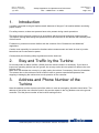
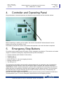
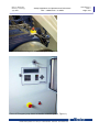
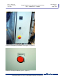
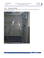
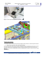
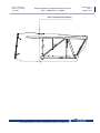
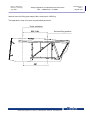
William Cundiff
From:
Sent:
To:
Cc:
Subject:
Attachments:
Chad Pepin [[email protected]]
Monday, November 01, 2010 2:44 PM
William Cundiff
Patricia Gates
Wind Turbine Safety Setbacks and concerns
Info - Vestas V90 Safety Manual.pdf; ATT00031.htm
Mr. Cundiff,
I've read through the Nordex Safety Manual, as well as the Vestas Safety Manual. I consider the Vestas manual
also a credible source of information since Vestas is the leading Wind Turbine manufacturer, with approx. 70%
market share worldwide.
In the Nordex Safety Manual on Page 52 it states:
DANGER! FALLING TURBINE PARTS In case of a fire in the nacelle or on the rotor, parts may fall off the wind turbine. In case of a fire,
nobody is permitted within a radius of 500 m (1640 ft) from the turbine.
In the Vestas (V90) Safety
Manual on Page 8 it states:
Do not stay within a radius of 400m (1300ft) from the turbine unless it is necessary.
From an engineering point of view, I'd consider these absolute minimum parameters, since they are related to safety and hazard zones.
Both manufacturers seem to agree that there is a real hazard zone where parts can "fall off" between 400m to 500m. Our research also
concurs with this. However, the setbacks established by the Developer and the ZBA in the variance are 305m (1000' ft) from dwellings,
(not property line). This is well within this hazard zone, which is a direct contradiction to the manufacturers recommendations. In most
cases, this will waive any liability from the manufacturer if an accident occurred.
If I take this data at face value, I'd strongly advise the ZBA and the Planning Board to reconsider the 1000 ft setback in light of this
information. At absolute minimum, the setbacks should be changed to 500m (1640) feet from all property lines (not dwellings) to assure
safety of anyone at any point on their property in the event of a fire or other turbine failure. Anything closer is clearly within the
manufacturer's hazard zone.
It is stated in the Variance Decision of May 13 2009 that:
" Although the Site Plan Review decision may dictate more extensive setbacks, in no event shall such decision decrease the number of
turbines below 13 or decrease the aggregate wind efficiency of the project as presented by by the applicant and analyzed by the Board
during the site plan review process."
The ZBA meeting of May 6, 2009 spent a lot of time on this specific language. It was agreed not to reduce the efficiency of the project,
but the verbal discussion also said that a health or safety issue would likely take some priority over a "project efficiency" issue.
The Douglas Wind Bylaw also speaks from the position health and safety and not about "project efficiency".
We have submitted quite a lot of information stating turbine failure can result in flying debris over 1500 ft, in some cases up to 3000 ft.
The Nordex safety manual validates all the information we've submitted.
I only see one way to interpret this:
1.) Keep the turbines a minimum of 500m (1640 feet)* from all properly lines, not just dwellings. Any area of property where a person
can stand, walk, play.... etc. should be out of the manufacturer's hazard zone. This includes state forest land where hikers and hunters
can be found.
2.) Fence in the entire hazard zone to assure no one can wander into the hazard zone unknowingly. The current plan is to fence in only
an area around the turbines. This doesn't protect hunters and hikers from wandering into the hazard zone.
* This is bare minimum. There should also be a "caution" buffer added to further assure safety. If the hazard (red) zone is 1640 feet,
this doesn't mean safety (green) zone is at 1641 feet. There should be a caution (yellow) zone, (for instance 20% or 300 feet) to be
established by the planning board or ZBA which will further ensure safety of nearby residents and wildlife.
A few words about the "Industry Standard" of 1000 feet: This is not an industry standard. This is a default the developers are using in
the absence of a standard. USA has not established a comprehensive wind siting code yet. This is similar to the construction industry
before 1974, when the BOCA code was first implemented. Plenty of structures were built prior to 1974, but construction is undoubtedly
better and safer today. This has not yet happened with wind turbines.
1
The safety zone should not be reduced or compensated by any fire suppression or automatic failure reducing gadgetry. This equipment
can fail. The hazard zone is established by the manufacturer as a passive safety measure in the event of total catastrophic failure.
Suppression methods and damage control methods (such as on site water supply) should be added to this passive safety measure. If
your car is equipped with an airbag, it doesn't mean you should drive faster and more recklessly. The goal is to reduce overall injuries to
ZERO - not to have one safety measure substitute for another.
"Fires and accidents rarely happen" is not an acceptable way of thinking. Most of us drive airbag equipped cars. The reason we have
airbags is because they are proven to reduce injury and they are there if we need them.
Allowing a wind project within the hazard zone of a residential area would be no different than ordering a new car with no airbags and
hoping for the best.
I don't see how this can be interpreted in any other way. This is clearly safety/hazard issue, not simply a nuisance issue. Further, this
Nordex manual does not take into consideration the heavily wooded site in Douglas. A burning turbine projectile flying 1640 feet could
likely start a forest fire wherever it lands.
Attached is the Vestas Safety Manual for your reference. You already have the Nordex manual.
Best regards,
Chad Pepin
--
2
APPENDIX O
OPERATION AND MAINTENANCE PLAN
630464 (5)
Class II
Item no.: 964106.R00
2007-06-29
Mechanical Operating and
Maintenance Manual
V90 – 3.0 MW, VCRS 60 Hz
Onshore/Offshore (Mk 7)
Vestas Wind Systems A/S · Alsvej 21 · 8900 Randers · Denmark · www.vestas.com
Item no.: 964106.R00
Issued by: Technology
Type: MAN
Mechanical Operating and Maintenance Manual
History of this Document
Date: 2007-06-29
Class: II
Page 2 of 4
History of this Document
Rev. no.
Date
Description of changes
00
2007-06-29
First edition
Table of Contents
1
2
3
4
Preface ..................................................................................................................................3
Updating of the Manual........................................................................................................3
The Header............................................................................................................................3
Contents................................................................................................................................4
Please see Mechanical Drawings & Parts List
Vestas Wind Systems A/S · Alsvej 21 · 8900 Randers · Denmark · www.vestas.com
Item no.: 964106.R00
Issued by: Technology
Type: MAN
Mechanical Operating and Maintenance Manual
Preface
1
Date: 2007-06-29
Class: II
Page 3 of 4
Preface
This manual applies to the wind turbine V90 - 3.0MW, VCRS 60 Hz, Mk-7.
It is the turbine owner’s responsibility that only qualified persons operate the
turbine.
Do not operate the turbine before, as a minimum, having studied the following
carefully:
960314
Safety Regulations for Operators and Technicians
950173
User Guide
Do not hesitate to contact your plant manager or Vestas’ Service Department if
you need more detailed explanations.
Vestas Wind Systems A/S
Alsvej 21
DK-8900 Randers
Telephone: +45 9730 0000
2
Updating of the Manual
The manual will continuously be brought up to date. Corrections to each specific
chapter are listed for the past year under the heading of “History of this
Document”.
3
The Header
The latest revision date of a specific chapter is stated in the header of the
chapter. Class II indicates that the document is only handed out according to
agreement with Vestas’ Technology Department.
Each specific chapter has its own item number followed by a revision number
(Rx).
First editions have revision number R0.
Vestas Wind Systems A/S · Alsvej 21 · 8900 Randers · Denmark · www.vestas.com
Item no.: 964106.R00
Issued by: Technology
Type: MAN
Mechanical Operating and Maintenance Manual
Contents
Date: 2007-06-29
Class: II
Page 4 of 4
4
Contents
Item no.
Title
Chapter
960314
Safety Regulations for Operators and Technicians
1
958627
Manual Rotor Lock
2
959055
Rescue Equipment RED Pro
3
946812
Conversion Tables
4
958640
Blades
5
963233
Blade Bearing
6
961109
Pitch System
7
958638
Gearbox
8
958630
Brake System
9
950270
Composite Coupling
10
963244
Gear Oil Lubrication System
11
958534
Generator and Transformer
12
958612
Yaw Gear
13
960304
Yaw Bearing System
14
958614
Hydraulic System
15
958636
Wind Sensor and Anemometer
16
958532
Air Conditioning System
17
950263
Tubular Tower
18
958637
Surface Treatment
19
958639
Lightning Current Transfer Unit
20
962638
Rotating Contact ND-end, Generator
21
962649
Rotating Contact in D-end
22
960301
Cooling System
23
958658
Rotating Transfer
24
963560
Mechanical Drawings & Parts List
25
Supplier Drawings
Item no.
Title
Chapter
963243
Gearbox Drawings
26
943674
Parking Brake Drawings
27
958610
Yaw Gear Drawings
28
963504
Generator Drawings
29
Vestas Wind Systems A/S · Alsvej 21 · 8900 Randers · Denmark · www.vestas.com
Item no.: 960314.R5
Issued by: Technology
Type: MAN
Safety Regulations for Operators and Technicians
V90 – 3.0MW/V100 – 2.75MW
Date 2006-09-11
Class: II
Page 1 of 32
Safety Regulations for Operators
and Technicians,
V90-3MW/V100-2.75MW
History of this Document
Rev. no.:
0
1
Date:
2005-06-23
2005-09-19
2
3
4
2006-01-17
2006-03-03
2006-05-08
5
2006-09-11
Description of change
First edition
947554 replaced by 959055;
Chap. 9: “However, the capacitors in the converter and AGO2
section might be energized.” inserted
Chapter 10 Converter and AGO2 Sections
Figure numbers updated
Reference to 947554 added again page 12
Chapter 18.1.1. New wind speed limit 23m/s
Language revision.
Inserted: section 14.2 Access to roof, text and picture.
Reference to V100 added
Section 19 updated with new pictures and new text.
Vestas Wind Systems A/S · Alsvej 21 · 8900 Randers · Denmark · www.vestas.com
Item no.: 960314.R5
Issued by: Technology
Type: MAN
Safety Regulations for Operators and Technicians
V90 – 3.0MW/V100 – 2.75MW
Date 2006-09-11
Class: II
Page 2 of 32
Contents ......................................................................................................Page
1.
2.
3.
4.
5.
5.1
5.2
5.3
6.
7.
8.
9.
10.
11.
12.
13.
14.
14.1
14.2
15.
16.
17.
18.
18.2
19.
Introduction ................................................................................................................................... 3
Stay and Traffic by the Turbine..................................................................................................... 3
Address and Phone Number of the Turbine ................................................................................. 3
Controller and Operating Panel .................................................................................................... 4
Emergency Stop Buttons .............................................................................................................. 4
Trip F60 ............................................................................................................................... 8
Lift (Optional)....................................................................................................................... 8
Internal Crane...................................................................................................................... 8
Practical Advice at Inspection....................................................................................................... 8
Influence by Lubricants................................................................................................................. 8
High Voltage Installations ............................................................................................................. 8
Grid Drop-Out ............................................................................................................................... 9
Converter and AGO2 Sections ..................................................................................................... 9
Turbine Standstill .......................................................................................................................... 9
Overspeed Guard ....................................................................................................................... 10
Inspection of the Turbine ............................................................................................................ 10
Safety Equipment ....................................................................................................................... 12
ResQ Emergency Rescue Equipment............................................................................... 13
Access to Roof .................................................................................................................. 14
Hooking Points and Safety Chains ............................................................................................. 15
Precautions in Case of Fire ........................................................................................................ 17
Directions for Use of Rotor Lock................................................................................................. 17
Operating the Rotor Locking System.......................................................................................... 19
Operating the Manual Rotor Locking System with Bolts ................................................... 21
Operating the Internal Crane ...................................................................................................... 25
Vestas Wind Systems A/S · Alsvej 21 · 8900 Randers · Denmark · www.vestas.com
Item no.: 960314.R5
Issued by: Technology
Type: MAN
1.
Safety Regulations for Operators and Technicians
V90 – 3.0MW/V100 – 2.75MW
Date 2006-09-11
Class: II
Page 3 of 32
Introduction
A turbine connected to the grid implies certain elements of danger if it is handled without exercising
proper caution.
For safety reasons, at least two persons have to be present during a work procedure.
The work must be properly carried out in accordance with this manual and other related manuals.
This implies, among other things that personnel must be instructed in and familiar with relevant parts
of this manual.
Furthermore, personnel must be familiar with the contents of the “Substances and Materials”
regulations.
Caution must especially be exerted in situations where measurement and work is done in junction
boxes that can be connected to power.
Consequently the following safety regulations must be observed.
2.
Stay and Traffic by the Turbine
Do not stay within a radius of 400m (1300ft) from the turbine unless it is necessary. If you have to
inspect an operating turbine from the ground, do not stay under the rotor plane but observe the rotor
from the front.
Make sure that children do not stay by or play nearby the turbine. If necessary, fence the foundation.
The access door to the turbine must be locked in order to prevent unauthorised persons from
stopping or damaging the turbine due to mal-operation of the controller.
3.
Address and Phone Number of the
Turbine
Note the address and the access road of the turbine in case an emergency situation should arise. The
address of the turbine can often be found in the service reports in the ring binders next to the ground
controller. Find the phone number of the local life-saving service.
Vestas Wind Systems A/S · Alsvej 21 · 8900 Randers · Denmark · www.vestas.com
Item no.: 960314.R5
Issued by: Technology
Type: MAN
4.
Safety Regulations for Operators and Technicians
V90 – 3.0MW/V100 – 2.75MW
Date 2006-09-11
Class: II
Page 4 of 32
Controller and Operating Panel
Only authorised or instructed persons are allowed to open the doors of the controller cabinet.
Picture 1
Before inspecting or working on the turbine, the remote control MUST be deactivated. Use the
breaker-key and set it in position “local”.
Remember to activate the remote control when the inspection or the work has been completed.
5.
Emergency Stop Buttons
For safety reasons please note the location of the 4 emergency stop buttons. The buttons are located
(Figure 1 Locations of emergency stop buttons and trip F60 in nacelle) at:
•
•
•
•
•
•
Ground controller (at the bottom of the turbine).
Gearbox (pos. 1).
Yaw ring (pos. 2).
Nose cone (pos. 3, only local stopping function)
Nacelle controller (pos. 4).
Trip F60 (pos. 5).
The emergency stop buttons are red with a yellow background. An emergency stop is activated by
pressing one of the red buttons. When an emergency stop is activated, the controller switches to
“EMERGENCY STOP” mode meaning that no power will be supplied to the contactor solenoids, the
blades will pitch (full feathering), the brake will be applied and the turbine will stop. The yaw system,
the hydraulic pump, the gear oil pump and the nacelle ventilator will also stop. Consequently, all
moving parts will be brought to a standstill.
However, the power supply to the light, the nacelle, the hub and the ground controllers will still be on.
The stop button in pos. 3 is not an emergency stop button but a local stopping function.
Vestas Wind Systems A/S · Alsvej 21 · 8900 Randers · Denmark · www.vestas.com
Item no.: 960314.R5
Issued by: Technology
Type: MAN
Safety Regulations for Operators and Technicians
V90 – 3.0MW/V100 – 2.75MW
Date 2006-09-11
Class: II
Page 5 of 32
Remember: The hydraulic system is still under pressure. Due to the accumulators, up to 6
litres of hot oil will pour out, if the hydraulic system is intervened.
Please note: When the emergency stop buttons are activated, the brake is activated.
Figure 1 Locations of emergency stop buttons and trip F60 in nacelle
Picture 2 Yaw ring emergency stop button (pos. 2, Figure 1)
Vestas Wind Systems A/S · Alsvej 21 · 8900 Randers · Denmark · www.vestas.com
Item no.: 960314.R5
Issued by: Technology
Type: MAN
Safety Regulations for Operators and Technicians
V90 – 3.0MW/V100 – 2.75MW
Picture 3 Gearbox emergency stop button (pos. 1, Figure 1)
Picture 4 Emergency stop button at nacelle controller (pos. 4, Figure 1)
Vestas Wind Systems A/S · Alsvej 21 · 8900 Randers · Denmark · www.vestas.com
Date 2006-09-11
Class: II
Page 6 of 32
Item no.: 960314.R5
Issued by: Technology
Type: MAN
Safety Regulations for Operators and Technicians
V90 – 3.0MW/V100 – 2.75MW
Picture 5 Emergency stop button in hub (pos. 3, Figure 1)
Picture 6 The trip F60 button (pos. 5, Figure 1)
Vestas Wind Systems A/S · Alsvej 21 · 8900 Randers · Denmark · www.vestas.com
Date 2006-09-11
Class: II
Page 7 of 32
Item no.: 960314.R5
Issued by: Technology
Type: MAN
5.1
Safety Regulations for Operators and Technicians
V90 – 3.0MW/V100 – 2.75MW
Date 2006-09-11
Class: II
Page 8 of 32
Trip F60
Trip F60 is situated on the nacelle controller (pos. 4). Trip F60 disconnects the high voltage supply for
the turbine. When disconnected, only the control system in the turbine is supplied from the UPS for
approx. 6 hours. Usually, the local power station must take part when the turbine is connected to the
grid.
5.2
Lift (Optional)
If a lift is installed, it has several emergency stop buttons.
Note: These buttons only stop the lift; emergency stop buttons for turbine do not apply to the lift.
5.3
Internal Crane
The crane is equipped with an emergency stop button. This only applies to the crane and otherwise
the emergency stop buttons in the turbine do not apply to the crane.
6.
Practical Advice at Inspection
When inspecting the machinery, always look very closely for oil spills and loose bolts. Dirt must be
wiped off, otherwise it can be difficult to determine whether there is a significant leak.
Loose bolts in the structure mean danger. They must be tightened immediately. If it is a matter of
several bolts or repetitions, please contact Vestas Wind Systems A/S service department.
7.
Influence by Lubricants
The lubricants used in the turbine can be aggressive. Lubricants must not
get in contact with skin or clothes.
At inspection of a gearbox if removing a cap while the oil is still hot, be
careful not to breathe in the hot oil vapours.
8.
High Voltage Installations
As a basic rule it is not allowed to dismount cover or open locked doors to the high voltage
installations.
An operator/service technician is only allowed to move around behind the covering when the high
voltage is disconnected, locked and visibly earthed. The work must be carried out and approved by
authorised personnel only (power station or selected coupling leader). One of these persons must
give permission to access the HV installation.
Work done on high voltage installations must be carried out in accordance with national regulations
and related Vestas Wind Systems A/S manuals.
Vestas Wind Systems A/S · Alsvej 21 · 8900 Randers · Denmark · www.vestas.com
Item no.: 960314.R5
Issued by: Technology
Type: MAN
9.
Safety Regulations for Operators and Technicians
V90 – 3.0MW/V100 – 2.75MW
Date 2006-09-11
Class: II
Page 9 of 32
Grid Drop-Out
A grid drop-out causes an EMERGENCY STOP. The blades pitch out of the wind (full feathering); the
yaw system, the hydraulic pump and the nacelle ventilator stop. Consequently, all moving parts will be
brought to a standstill except for emergency lubrication system for the gearbox. The power supply for
the light and the nacelle, hub and ground controllers is partly off. However, the capacitors in the
converter and AGO2 section might be energized.
10. Converter and AGO2 Sections
WARNING:
If working on the converter section or AGO2 section, note that the capacitors inside can be
charged to 800 V and those in the filters can be charged to 690 V. The capacitors are discharged
to below 50 V in 5 minutes after disconnection from the grid. Switch Q7 and Q8 must be turned
off.
Before opening the cabinet, check the DC-link-voltage in picture 17.
Before working on the converter/AGO2, check the DC-link-voltage with a Fluke multimeter.
11. Turbine Standstill
After a period of maximum 14 days without grid connection, necessary equipment for humidity- and
temperature control must be installed in the turbine in order to fulfil the following requirements:
•
•
•
•
For 90 % of the shutdown period, the relative humidity (RH) must not exceed 45 %.
The RH must be between 45% and 60% for max. 10% of the shutdown period only.
Within a period of 12 hours, the temperature in the turbine must not drop more than 10° C.
The temperature and humidity must be logged.
During a period without grid connection, the following inspections must be carried out on a monthly
basis:
•
•
•
•
•
•
Check the functionality of the equipment as regards humidity and temperature.
Check the RH and temperature logging in accordance with the requirements mentioned
above.
Check the emergency lubrication.
Recharge emergency lubrication batteries (only every 3 months).
Check the blade locking system.
Check that the brake is released and without pressure.
Vestas Wind Systems A/S · Alsvej 21 · 8900 Randers · Denmark · www.vestas.com
Item no.: 960314.R5
Issued by: Technology
Type: MAN
Safety Regulations for Operators and Technicians
V90 – 3.0MW/V100 – 2.75MW
Date 2006-09-11
Class: II
Page 10 of 32
12. Overspeed Guard
If the turbine rotation exceeds its limit, the overspeed guard (VOG) is activated, and the turbine will go
into EMERGENCY STOP mode. The state of failure cannot be reset until the VOG has been deenergized.
13. Inspection of the Turbine
At inspection of the turbine, the following procedure must be followed.
When inspecting the turbine there must always be at least two persons present.
Full feathering of the blades is done by pressing <PAUSE>. When the rotor comes to a standstill or
rotates slowly, activate the <Emergency stop button> to stop the turbine.
It is now possible to climb the turbine but remember as a minimum to wear:
• Safety footwear suitable for climbing towers.
• H-belt with fall protection device fastened directly to the H-belts D-ring on your chest.
• Safety helmet.
Always make sure that there is nobody above you in the turbine when you start the ascent.
If you bring tools, lubricants etc. with you, keep these in a rucksack or a bag which is attached to the
safety belt.
During the ascent the fall protection and the supporting strap MUST be mounted. Do not mount the
fall protection hook on the aluminium ladder rungs or on the fittings for the ladder, as they might brake
in case of falling. Instead the swivel eye plate (yellow) must be used.
Close the trap doors of the landings when passing them.
Please notice the location of the emergency stop buttons and Trip F60 in the nacelle.
When working on the electrical part of the controller, the controller must be disconnected by the circuit
breaker (marked Q7, Q26 and Q27) in the board arrangement and locked by means of a padlock.
Only authorised personnel must have access to the key/keys.
When working on the terminal of the generator, inspecting the generator cables or the controlling as
such, the generator must be disconnected by the circuit breaker (Q8 and Q23) in the board
arrangement and locked by means of a padlock. Only authorised personnel must have access to the
key/keys.
When working on the yaw system, the yaw motors must be disconnected in the control panel at the
contactors F35.1 and F35.2.
Always make sure that there is nobody below the turbine while you are working in the nacelle. Even a
small screw is highly dangerous when falling from a height of 60m or more.
Unauthorised persons must under no circumstances move the covering plates which cover rotating or
electrical parts, especially the high voltage installation. Be cautious that safety straps are not caught
on any rotating shafts during stay in the nacelle while the turbine is in operation.
Vestas Wind Systems A/S · Alsvej 21 · 8900 Randers · Denmark · www.vestas.com
Item no.: 960314.R5
Issued by: Technology
Type: MAN
Safety Regulations for Operators and Technicians
V90 – 3.0MW/V100 – 2.75MW
Date 2006-09-11
Class: II
Page 11 of 32
Before entering the hub or working on rotating parts in the nacelle, make sure that the rotor is locked
and that the blades are fully feathered. See section “Operating the Rotor Locking System” on how to
activate the rotor locking system.
Before descent, close the nacelle skylights and the service hatch. Make sure that you have gathered
all tools and remember that the red emergency stop buttons must be off.
If the blades are iced up, it is highly dangerous to stay below or close to the rotor. If the turbine is to
be restarted with iced up blades, the operator must be very careful and make sure that no persons
are nearby because of the risk of falling pieces of ice.
Do not stay in the nacelle while the turbine is in operation, unless if checking for gear and generator
noise.
Any oil or grease spills must be cleaned up because of the risk of slipping.
Make sure that the covering and the locking of the high voltage installations are undamaged.
Make sure that the high voltage cable between the high voltage installations in the nacelle and the
bottom are undamaged and do not have any visible mechanical damages, such as having been
squeezed/cut by cable binders, mechanical parts etc.
When working in the nacelle, spinner or roof, please pay attention to safety hooking points. See figure
3.
When working on the roof of the nacelle, secure a safety line on the roof rail. See Picture 11 Hooking
points on the roof.
Special caution must be taken when climbing lattice towers when it is wet or icy. Moreover special
cautions must be taken when climbing on the outside of the lattice tower, since the back of the blade
is close to the lattice tower when the blade is turning around its longitudinal axis. This happens if
anyone pushes <PAUSE> or <EMERGENCY STOP> and also at an unintended EMERGENCY
STOP.
Vestas Wind Systems A/S · Alsvej 21 · 8900 Randers · Denmark · www.vestas.com
Item no.: 960314.R5
Issued by: Technology
Type: MAN
Safety Regulations for Operators and Technicians
V90 – 3.0MW/V100 – 2.75MW
Date 2006-09-11
Class: II
Page 12 of 32
14. Safety Equipment
See Figure 2 Safety Equipment
1.
2.
3.
Safety helmet.
H-belt (delivered by Vestas).
Lanyards: one line with a fall damper device, one line with a shortening device (delivered by
Vestas).
Fall protection device (delivered by Vestas).
Rubber-soled footwear properly tightened.
4.
5.
1
2
3
3
5
4
Figure 2 Safety Equipment
When climbing the tower, fasten the fall protection device directly to the H-belt's D-ring. Only one
person is allowed on each ladder section at a time.
If a service lift is installed in the turbine, bring along the safety equipment in it.
Vestas Wind Systems A/S · Alsvej 21 · 8900 Randers · Denmark · www.vestas.com
Item no.: 960314.R5
Issued by: Technology
Type: MAN
14.1
Safety Regulations for Operators and Technicians
V90 – 3.0MW/V100 – 2.75MW
Date 2006-09-11
Class: II
Page 13 of 32
ResQ Emergency Rescue Equipment
In case the escape route via the tower should be cut off by fire or other unforeseen events, a rescue
and descent device is located in the nacelle behind the main controller section in an aluminium box.
Please see user manual for rescue equipment, item number 959055 (VCS, 50 Hz turbines) or 947554
(VCRS, 60 Hz turbines).
Picture 7 Fixing Point for ResQ descent device
•
•
•
•
•
Fixing point for ResQ descent device.
Open the left service hatch.
Lift the arm above the opening.
Fasten the ResQ descent device to the arm.
Ready for lowering, SWL 2000kg.
Vestas Wind Systems A/S · Alsvej 21 · 8900 Randers · Denmark · www.vestas.com
Item no.: 960314.R5
Issued by: Technology
Type: MAN
14.2
Safety Regulations for Operators and Technicians
V90 – 3.0MW/V100 – 2.75MW
Date 2006-09-11
Class: II
Page 14 of 32
Access to Roof
Place the ladder on machine foundation at the rear of the nacelle to gain access to nacelle roof as
shown in the picture below.
Picture 8 Ladder to roof
Vestas Wind Systems A/S · Alsvej 21 · 8900 Randers · Denmark · www.vestas.com
Item no.: 960314.R5
Issued by: Technology
Type: MAN
Safety Regulations for Operators and Technicians
V90 – 3.0MW/V100 – 2.75MW
Date 2006-09-11
Class: II
Page 15 of 32
15. Hooking Points and Safety Chains
A number of hooking points is installed at different locations in the nacelle. A hooking point is shown
in Picture 9 Hooking point.
Figure 3 Hooking points in the nacelle and position of safety chains
Picture 9 Hooking point
Vestas Wind Systems A/S · Alsvej 21 · 8900 Randers · Denmark · www.vestas.com
Item no.: 960314.R5
Issued by: Technology
Type: MAN
Safety Regulations for Operators and Technicians
V90 – 3.0MW/V100 – 2.75MW
Picture 10 Safety chains must be mounted when the bottom hatch is open (Figure 3)
Picture 11 Hooking points on the roof
Vestas Wind Systems A/S · Alsvej 21 · 8900 Randers · Denmark · www.vestas.com
Date 2006-09-11
Class: II
Page 16 of 32
Item no.: 960314.R5
Issued by: Technology
Type: MAN
Safety Regulations for Operators and Technicians
V90 – 3.0MW/V100 – 2.75MW
Date 2006-09-11
Class: II
Page 17 of 32
16. Precautions in Case of Fire
At any type of fire in or near a turbine, the power to the turbine must always be disconnected at the
main high voltage circuit breaker. To disconnect supply, switch off by pushing the red button (marked
TRIP F60) on the nacelle controller in the nacelle. In the tower bottom the power supply is switched
off by pushing the red button situated on the breaker in the high voltage section. If it is impossible to
get to the main circuit breaker, contact the power station for a disconnection of the grid.
In case of a fire during an uncontrolled operation, do under no circumstances approach the turbine.
Evacuate and rope off the turbine in a radius of minimum 400m (1300ft). In case of a fire in a nonoperating turbine, the fire can be put out by means of a powder extinguisher.
Use of a CO2 extinguisher in a closed room can result in lack of
oxygen.
17. Directions for Use of Rotor Lock
To avoid accidents and near-accidents, which can be prevented via mechanical locking of the rotor,
the following guidelines must be followed:
IN GENERAL:
Besides following the requirements listed in this document, it is important also to use ones
common sense and assess the specific situations.
When the wind speed exceeds the values of the mechanical design of the locking system, it is not
allowed to work in a turbine as listed below.
A technical solution must be prepared before starting work on a turbine that cannot be locked
mechanically.
The work listed below must not be carried out before the turbine has been mechanically locked.
Mechanical rotor locking must be used in connection with:
1.
Hub and blades:
a. stay in hub and nose cone
b. stay on/near the blade is not allowed unless both the rotor and the blade has been locked
2.
a.
b.
c.
d.
3.
Work on gearbox and gear oil system if this involves:
disassembly and adjustment of mechanical parts
tensioning
activation of shrink disc
internal inspection – unless it is a visual inspection
Work on coupling and braking system if this involves:
a. disassembly and adjustment of mechanical parts
Vestas Wind Systems A/S · Alsvej 21 · 8900 Randers · Denmark · www.vestas.com
Item no.: 960314.R5
Issued by: Technology
Type: MAN
Safety Regulations for Operators and Technicians
V90 – 3.0MW/V100 – 2.75MW
Date 2006-09-11
Class: II
Page 18 of 32
b. tensioning
c. inspection of coupling
d. lubrication
4.
Work on generator if this involves:
a. disassembly and adjustment of mechanical parts
b. tensioning
c. work on slip ring systems/units
5.
Work on yaw system
In addition to rotor locking, the turbine must be secured against unintentional yawing, if this
involves:
a. disassembly of mechanical parts
b. yaw brakes cannot be activated
6.
Work on electricity in the nacelle, if this involves:
a. that the turbine controller is switched off and work at rotating parts of the drive train has to be
carried out.
7.
Work on hydraulics for pitch as well as brake system, if this involves
a. disassembly of mechanical parts
b. that the pumps are out of operation
8.
Work on the turbine’s exterior
In addition to rotor locking, the turbine must be secured against yawing, if this involves:
a. use of crane
b. use of front lift
c. use of other lifts or scaffold systems
9.
Replacement of components, if this involves:
a. replacement of components, sensors, etc. close to unshielded rotating parts of the drive train.
Vestas Wind Systems A/S · Alsvej 21 · 8900 Randers · Denmark · www.vestas.com
Item no.: 960314.R5
Issued by: Technology
Type: MAN
Safety Regulations for Operators and Technicians
V90 – 3.0MW/V100 – 2.75MW
Date 2006-09-11
Class: II
Page 19 of 32
18. Operating the Rotor Locking System
The rotor must not be locked unless it is necessary, however always when servicing the hub and it
must be unlocked as soon as possible after the service operation, which caused the locking.
If the rotor has to be locked for more than 48 hours, it must be bolted to the main foundation, following
the procedure description in section 18.2.
18.1.1
Operating the hydraulic rotor locking system for normal service
The rotor locking system must not be set or used at wind speeds exceeding 23 m/s.
The rotor locking system must not be used while the rotor is rotating.
Pitching of blades is not allowed while the rotor is locked, except at wind speeds below 15
m/s. In this case only one blade may be pitched at a time.
The rotor locking system is located at the upper right hand side of the main gear,
see Picture 12 Rotor locking system.
1.
Set the turbine to PAUSE mode and select test picture 11.7 (Manual Pitch and Brake), where
the brake can be activated.
2.
Align the locking system position holes in the hub with the locking system mandrels by
"manoeuvring" the brake (press [ * ]) until the V-notch marking (pos. 1) on the hub is aligned
with pointer on machine foundation (see pos. 2). See Picture 13.
3.
At the correct position set the handle in "+" position and pump the locking system mandrels
out. Observe at the right side during the pumping! See Figure 4.
4.
The locking takes place with the hydraulic hand pump located above the main gear on right
hand side. The locked position of the handle is 45°. When locking set the handle in ”+" position
(the handle perpendicular to the gearbox centre shaft). When unlocking set the handle in "-"
position and pump in the locking system mandrels.
5.
When the mandrels are fully out or in, set the handle in "lock" position, see Figure 4.
Verify the fully in or out position by looking at picture 11.7.B at the operator panel.
Vestas Wind Systems A/S · Alsvej 21 · 8900 Randers · Denmark · www.vestas.com
Item no.: 960314.R5
Issued by: Technology
Type: MAN
Safety Regulations for Operators and Technicians
V90 – 3.0MW/V100 – 2.75MW
Date 2006-09-11
Class: II
Page 20 of 32
Hydraulic hand
pump
Upper locking
mandrel
Picture 12 Rotor locking system
Picture 13 Alignment markings seen from machine foundation side
Vestas Wind Systems A/S · Alsvej 21 · 8900 Randers · Denmark · www.vestas.com
Item no.: 960314.R5
Issued by: Technology
Type: MAN
Safety Regulations for Operators and Technicians
V90 – 3.0MW/V100 – 2.75MW
Date 2006-09-11
Class: II
Page 21 of 32
Figure 4 Handle positions
18.2
Operating the Manual Rotor Locking System with Bolts
The manual rotor locking system is used in case of servicing:
• Gearbox repairs
• Gearbox replacements
• Transport of nacelle
• Turbine standstill for long period of time: > 48 hours
The manual rotor lock must be used as an alternative to the hydraulic rotor lock
The following components must be used when operating the manual rotor lock.
Item number
950461
782137
782138
782139
782142
782141
Description
Centering mandrels
M42 special nut
Washer
M42 special bolt
Shim for rotor lock
Hex.soc.h.scr.M16x60 yellow
Quantity
3
16
16
16
16
16x8 = 128
Prior to mounting the manual rotor lock:
•
Set the turbine in PAUSE mode and activate the <emergency stop button> to activate the disc
brake.
Vestas Wind Systems A/S · Alsvej 21 · 8900 Randers · Denmark · www.vestas.com
Item no.: 960314.R5
Issued by: Technology
Type: MAN
18.2.1
1.
2.
3.
4.
5.
6.
Safety Regulations for Operators and Technicians
V90 – 3.0MW/V100 – 2.75MW
Date 2006-09-11
Class: II
Page 22 of 32
Mounting the manual rotor lock
Turn the hub until the highest point points up and one of the blade bearings points downwards.
Lock the rotor with the hydraulic rotor lock or mount the three centering mandrels using 3 x 2
M20x40 from in front of the hub flange and into the locking holes of the main foundation.
Place 16 x M42 bolts (782139) 5 on each side and 6 in the top.
Insert 16 shims (782142) so the bolt is placed in the slot and the shims. Use a small hammer
for mounting to ensure there is no space between the shim and the hub/main foundation.
Screw on the special nut, with washer underneath so it hits the hub flange.
Tighten the yellow M16 special bolts (782141) following this procedure:
Tighten the 8 M16 bolts to 70Nm. Then tighten the 8 M16 bolts to 140Nm in a circular way and
proceed with this operation with the first 3 bolts again, so you at the end have tightened 11
bolts to 140Nm.
(see figure on the following page)
Vestas Wind Systems A/S · Alsvej 21 · 8900 Randers · Denmark · www.vestas.com
Item no.: 960314.R5
Issued by: Technology
Type: MAN
Safety Regulations for Operators and Technicians
V90 – 3.0MW/V100 – 2.75MW
Date 2006-09-11
Class: II
Page 23 of 32
Do not at any time remove the centering mandrels when the M 16
bolts are not tightened.
Figure 5
Vestas Wind Systems A/S · Alsvej 21 · 8900 Randers · Denmark · www.vestas.com
Item no.: 960314.R5
Issued by: Technology
Type: MAN
18.2.2
1.
2.
3.
4.
Date 2006-09-11
Class: II
Safety Regulations for Operators and Technicians
V90 – 3.0MW/V100 – 2.75MW
Page 24 of 32
Dismantling the manual rotor lock after service work
Loosen all the M16 special bolts.
Loosen and remove all M42 special nuts.
Remove all the M42 special pin bolts
Remove the centering mandrels or pull back the hydraulic rotor lock.
Centering mandrel (950461)
Figure 6
950084.R1
Bolt M42x200 (782139)
Washer
(782138)
M 42 nut
(782137)
Spec. bolt M16 (782141)
Vestas Wind Systems A/S · Alsvej 21 · 8900 Randers · Denmark · www.vestas.com
Shim (782142)
Item no.: 960314.R5
Issued by: Technology
Type: MAN
Safety Regulations for Operators and Technicians
V90 – 3.0MW/V100 – 2.75MW
Date 2006-09-11
Class: II
Page 25 of 32
All these components are shown in an additional document 958627.
19. Operating the Internal Crane
Limitations on use:
• Lift or landing to floating vessels is not permitted for any crane constellation.
• Lift or lowering of personnel is not permitted for any crane constellation.
• Do not use any of the crane constellations for external operation above wind speed 15 m/sec
10 min.
• Do not operate the crane without correct authorization.
After 50 lifts with 12000 kg load the crane must be recertified:
• Inspect all welding on both trolleys for cracks. Repair or replace damaged items.
• Inspect all welding on lattice construction for cracks. In case of cracks Vestas Technology
must be contacted.
• Replace all bolts, nuts and washers on bridge and trolley.
• Check rollers for free rotation, replace if malfunction.
• Perform overload test.
Attach chain to prevent accidental access to hazardous area.
Open the service hatch and secure it to transformer partition wall.
Keep the service hatch closed after hoisting operation is completed.
The internal crane and the traverse must be fastened in parked position when turbine in operation.
Figure 7 Attach chain
Vestas Wind Systems A/S · Alsvej 21 · 8900 Randers · Denmark · www.vestas.com
Item no.: 960314.R5
Issued by: Technology
Type: MAN
Safety Regulations for Operators and Technicians
V90 – 3.0MW/V100 – 2.75MW
Figure 8 Service Hatch
Release the chain from the chain box.
Figure 9 The chain box
The crane can be moved longitudinally by a winch mounted on the machine foundation.
Vestas Wind Systems A/S · Alsvej 21 · 8900 Randers · Denmark · www.vestas.com
Date 2006-09-11
Class: II
Page 26 of 32
Item no.: 960314.R5
Issued by: Technology
Type: MAN
Safety Regulations for Operators and Technicians
V90 – 3.0MW/V100 – 2.75MW
Date 2006-09-11
Class: II
Page 27 of 32
Figure 10 The Crane Winch placed on foundation.
Figure 11 The crane in parked position
General crane functions:
The internal nacelle overhead traverse trolley support 4 lifting functions, each with specific manual.
• Normal service operation. Max. Work load is 800 kg.
Prior to lowering the trolley must be locked in sideways direction by tightening lock screws ¼ extra
turn after contact and in longitudinally direction locked by keeping the steel wire tensioned and
tightening lock screw for longitudinally direction by tightening lock screws ¼ extra turn after contact .
Warning:
Visual inspect:
Vestas Wind Systems A/S · Alsvej 21 · 8900 Randers · Denmark · www.vestas.com
Item no.: 960314.R5
Issued by: Technology
Type: MAN
•
•
Safety Regulations for Operators and Technicians
V90 – 3.0MW/V100 – 2.75MW
Date 2006-09-11
Class: II
Page 28 of 32
The bridge and trolley for corrosion, wear, defect bolts and connections before using the
crane.
Winch for oil/grease leaks and corrosion.
The crane must not be used before defects are repaired.
Service crane work range.
Restricted area.
Crane movements.
Lock screws for
longitudinally
direction.
Vestas Wind Systems A/S · Alsvej 21 · 8900 Randers · Denmark · www.vestas.com
Lock screws
for sideways
directions.
Item no.: 960314.R5
Issued by: Technology
Type: MAN
Safety Regulations for Operators and Technicians
V90 – 3.0MW/V100 – 2.75MW
Date 2006-09-11
Class: II
Page 29 of 32
• Lifting transformer. Max. work load is 12000 kg.
This operation is only to be done by authorized personnel.
Transformer lowering position.
Transformer lifting position.
• Lifting generator. Max. Work load is 12000 kg.
This operation is only to be done by authorized personnel.
Vestas Wind Systems A/S · Alsvej 21 · 8900 Randers · Denmark · www.vestas.com
Item no.: 960314.R5
Issued by: Technology
Type: MAN
Safety Regulations for Operators and Technicians
V90 – 3.0MW/V100 – 2.75MW
Date 2006-09-11
Class: II
Page 30 of 32
Generator lowering.
Internal crane for lifting components in the hub:
This operation is only to be done by authorized personnel.
Vestas Wind Systems A/S · Alsvej 21 · 8900 Randers · Denmark · www.vestas.com
Item no.: 960314.R5
Issued by: Technology
Type: MAN
Safety Regulations for Operators and Technicians
V90 – 3.0MW/V100 – 2.75MW
Hub components position.
Vestas Wind Systems A/S · Alsvej 21 · 8900 Randers · Denmark · www.vestas.com
Date 2006-09-11
Class: II
Page 31 of 32
Item no.: 960314.R5
Issued by: Technology
Type: MAN
Safety Regulations for Operators and Technicians
V90 – 3.0MW/V100 – 2.75MW
Internal crane for lifting gear stages, Max. work load is 12000 kg:
This operation is only to be done by authorized personnel.
Tower centerline.
Service lifting position.
Vestas Wind Systems A/S · Alsvej 21 · 8900 Randers · Denmark · www.vestas.com
Date 2006-09-11
Class: II
Page 32 of 32