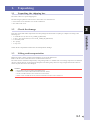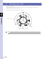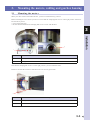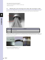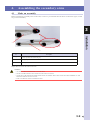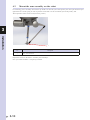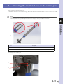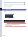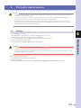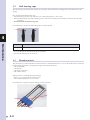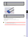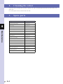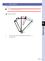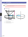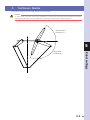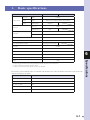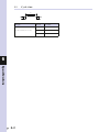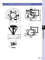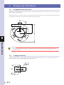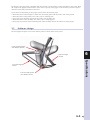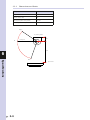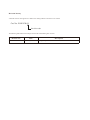
1
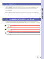
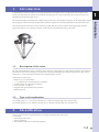
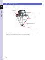
Cat. No. I199E-EN-01
Washdown Delta Robot
ZX-T Series
CR_UGD4_HD
Series
Delta Robot IP69K
USER´S MANUAL
CONTENTS
CR_UGD4_HD
User's Manual
Safety Instructions
1. Attention
S-1
2. Explanation of warnings and notes
S-1
3. Safety information
S-2
3.1
General
S-2
3.2 Qualifiedpersonnel
S-2
3.3 Liability
S-2
3.4 Installation and operating conditions
S-2
3.5 Residual risks
S-2
3.5.1
3.5.2
3.5.3
3.5.4
3.5.5
Release device
Transport
Assembly and start-up
Maintenance and repair
System integrator
Chapter 1
Introduction
1. Introduction
1.1
S-3
S-3
S-3
S-3
S-4
1-1
Description of the robot
1.2 Type code explanation
1-1
1-1
2. Identification
1-1
3. Part names
1-2
Chapter 2
Model overview
1. Overview
Chapter 3
2-1
Installation
1. Unpacking
1.1
Unpacking the shipping box
3-1
3-1
1.2 Check the damage
3-1
1.3 Lifting and transportation
3-1
2. Mounting the robot
3-2
3. Mounting the motors, cabling and gearbox housing
3-3
3.1
Mounting the motors
3-3
3.2 Mounting the gearbox housing into the body and connecting the cables
3-4
3.3 Mounting the covers
3-8
T-1
CONTENTS
4. Assembling the secondary arms
4.1
Make an assembly
4.2 Mount the arm assembly on the robot
User's Manual
3-9
3-9
3-10
5. Mounting the rotational axis on the cardan joint
3-11
6. Calibration
3-12
Chapter 4
Maintenance
1. Periodic maintenance
1.1
Springs
4-1
4-1
1.2 Ball bearing cups
4-2
1.3 Rotational axis
4-2
2. Cleaning the robot
4-4
3. Spare parts
4-4
Chapter 5
Robot settings
1. Kinematics
5-1
2. Workspace
5-2
3. Software limits
5-3
Chapter 6
Specifications
1. Basicspecifications
1.1
Cycle time
6-1
6-2
2. External view and dimensions
6-3
3. Designspecifications
6-4
3.1
Occupation area of robot
6-4
3.2 Gripper interface
6-4
3.3 Software design
6-5
3.3.1
T-2
CR_UGD4_HD
Dimensions and limits
6-6
Safety Instructions
Contents
1.
Attention
S-1
2.
Explanation of warnings and notes
S-1
3.
Safety information
S-2
3.1
General
S-2
3.2
Qualified personnel
S-2
3.3
Liability
S-2
3.4
Installation and operating conditions
S-2
3.5
Residual risks
S-2
3.5.1
3.5.2
3.5.3
3.5.4
3.5.5
Release device
Transport
Assembly and start-up
Maintenance and repair
System integrator
S-3
S-3
S-3
S-3
S-4
1.
Attention
Information in this document can change without prior notice.
No part of this manual and added documentation may be copied, reproduced or translated into another language without
prior written approval.
Read and understand the material contained in this user's manual before you work on the CR_UGD4_HD robot for
the first time. This user's manual is supposed to help you use the capabilities of the CR_UGD4_HD robot safely and
properly.
2.
Explanation of warnings and notes
This manual uses the following safety alert symbols and signal words to provide safety instructions that must be
observed and to describe handling precautions, prohibited actions, and compulsory actions. Make sure you understand
the meaning of each symbol and signal word and then read this manual.
DANGER
THIS INDICATES AN IMMEDIATELy HAzARDOUS SITUATION WHICH, If NOT AVOIDED, WILL RESULT IN DEATH OR
SERIOUS INjURy.
WARNING
THIS INDICATES A POTENTIALLy HAzARDOUS SITUATION WHICH, If NOT AVOIDED, COULD RESULT IN DEATH OR
SERIOUS INjURy.
NOTE
Explains the key point in the operation in a simple and clear manner.
S-1
Safety Instructions
OMRON EUROPE B.V. cannot be hold responsible for any damage to the environment, to the machine or to the
functioning of the machine occurred by errors or missing data in the illustrations, drawing or specifications.
3.
Safety information
3.1
General
Safety Instructions
This ´3. Safety information´ subchapter contains information regarding working with the CR_UGD4_HD robot.
Qualified personnel working with the CR_UGD4_HD robot must have read and understood the CR_UGD4_HD robot
documentation, including the safety information chapter.
3.2
Qualified personnel
These are people who, due there specialist training, knowledge and experience, and their familiarization with the
relevant standards, are able to assess the work to be carried out and detect any potential hazards.
3.3
Liability
The CR_UGD4_HD robot is build using state-of-the-art technology and in accordance with the recognized safety rules.
Nevertheless, misuse of the CR_UGD4_HD robot may constitute a risk to life and limb or cause damage to the CR_
UGD4_HD robot and to other material property.
3.4
Installation and operating conditions
you may only use the components in accordance with the installation and operating conditions described in the
documentation. The operating conditions at the installation location must be checked and maintained in accordance
with the required technical data. Within the meaning of the Machinery Directive the CR_UGD4_HD robot is an
incomplete machine. Commissioning is prohibited until the usable machine or system in which the CR_UGD4_HD
robot is installed meets all requirements of the Machine directive 2006/42/EC.
for the CR_UGD4_HD robot you have to observe the following standards, directives and regulations:
• ENISO10218-1:2011Robotsandroboticdevices-Safetyrequirementsforindustrialrobots-Part1:Robots.
• ENISO10218-1:2011Robotsandroboticdevices-Safetyrequirementsforindustrialrobots-Part2:Robotsystems
and integration.
3.5
Residual risks
Safety and health risks arising from the robot mechanics have been reduced by means of safety technology and design
engineering. However a residual risk remains, since the robot mechanics will be move by an automated control system.
The following are typical warnings concerning residual risks which cannot be assigned to a specific action. The
expression of safety labels is identical to the safety information.
S-2
3.5.1
Release device
The robot mechanics are not supplied with an release switch to control the brakes of the motors.
3.5.2
Transport
The prescribed transport position of the robot must be observed. Transportation must be carried out in accordance with
the transportation instructions or assembly instructions of the robot.
WARNING
• ONlyuSEauthORIzEDhaNDlINgEQuIPMENtwIthaSuffIcIENtlOaD-BEaRINgcaPacItytOtRaNSPORt
THE ROBOT.
• wEaRSuItaBlEPROtEctIvEclOthINgIfNEcESSaRy.
3.5.3
Assembly and start-up
Before starting up systems and devices for the first time, a check must be carried out to ensure that the system and
devices are completed and operational, that they can be operated safely and that any damage is detected.
The valid national or regional work safety regulations must be observed for this check. The correct functioning of all
safety circuits must also be tested.
The following tests must be carried out before start-up and recommissioning. It must be ensured that:
• therobotiscorrectlyinstalledandfastenedinaccordancewiththespecificationsintheassemblyinstructions.
• therearenoforeignbodiesorloosepartsontherobot.
• allrequiredsafetyequipmentiscorrectlyinstalledandoperational.
WARNING
• awRONgINStallEDROBOtMaythROwOffhISaRMS.
• wEaRSuItaBlEPROtEctIvEclOthINgIfNEcESSaRy.
3.5.4
Maintenance and repair
After maintenance and repair work, checks must be carried out to ensure the required safety level. The valid national
or regional work safety regulations must be observed for this check. The correct functioning of all safety circuits must
also be tested.
The purpose of maintenance and repair work is to ensure that the system is kept original or, in the event of a fault, to
return the system to an operational state. Repair work includes troubleshooting in addition to the actual repair itself.
The following safety measures must be carried out when working on the robot:
• Switchofthemachine(system)wheretherobotisbuilt-in(e.g.withapadlock)topreventitfrombeingswitchedon
again
• labelthemachine(system)withasignindicationthatworkisinprogress.thissignmustremaininplace,even during temporary interruptions to the work.
• theemergencystopfromthemachine(system)mustremainactive.Ifsafetyfunctionsorsafeguardsaredeactivated
during maintenance or repair work, they must be reactivated immediately after the work is completed.
S-3
Safety Instructions
WARNING
• MOuNtaRElEaSESwItchONthEMachINESOthEaRMS(MOtOR)OfthEROBOtcOulDBEMaNually MOVED.
• MOvINgaNaxISwIthaNIMPROPERlywORkINgRElEaSESwItchcaNDaMagEthEMOtORBRakE.thIS CAN RESULT IN PERSONAL INjURy AND MATERIAL DAMAGE.
• BEfORERElEaSINgthEBRakE,yOuhavEtOBESuREthatNOONEISINthEhazaRDaREaOfthEROBOt.
3.5.5
System integrator
The robot is safely integrated into a complete system by the system integrator. The system integrator is responsible for
the following tasks:
Safety Instructions
• Installingtherobot
• Performingriskassessment
• Implementingtherequiredsafetyfunctionsandsafequards
• Issuingthedeclarationofconformity
• attachingthecEmark
• creatingtheoperatinginstructionsforthecompletesystem
S-4
Chapter 1 Introduction
Contents
1.
Introduction
1-1
1.1
Description of the robot
1-1
1.2
Type code explanation
1-1
2.
Identification
1-1
3.
Part names
1-2
1.
Introduction
Congratulations with the purchase of your high speed Delta robot IP69K. This is a high speed pick and place robot
which uses state-of-the-art stainless steel materials and the latest servo drive technology to be put in use in the most
demanding pick and place applications.
This manual describes the main versions of the CR_UGD4_HD robot, and all options. Where applicable check the
appropriate data for your robot type, the type can be found on the identification tag of the robot.
1.1
Description of the robot
The CR_UGD4_HD Delta robot is a high speed pick and place robot which uses state-of-the-art stainless steel materials
and the latest servo drive technology to be put in use in the most demanding pick and place applications. The robot is
designedasa3-axis(optional4throtationalaxis)Deltakinematicsystem.
Characteristics of the robot:
• Requiresverylowmaintenance
• 3+1(rotationalaxisoptional)degreesoffreedom
• compactdesignformountinginamachine
• lownoiselevel<68dB(a)
• EquippedwithspecialDeltarobotgearboxes
• IP69kprotection
1.2
Type code explanation
cR_ugD4_R_hD:3+1axes(withrotationalaxis),1100mmworkingrange,max.payload:2kg
cR_ugD4_NR_hD:3axes(withoutrotationalaxis),1100mmworkingrange,max.payload:2kg
2.
Identification
On the robot base plate an identification tag is mounted, important data on this plate:
• Robottype
• totalweightoftherobot
• yearofproduction
• Serialnumber,importantfororderingspareparts
1-1
Introduction
This manual should be read before the commissioning of the robot. By mechanical engineers in the design phase during
the integration of the robot in the machine and by software engineers to check the performance envelope of the robot.
1
3.
1
Part names
CR_UGD4_HD
Introduction
Cover
Primary arm
Cable entry tube
Rotational axis
Secondary arm
TCP (Tool Center Point)
The CR_UGD4_HD robot consists of three radially placed axis which give the TCP freedom to move in three
directions,x,yandz.anoptionalfourthaxiscantakecareoftherotation,Rz,ofthetcP.
Optionally the robot is equipped with an extra servo motor for the rotational axis.
1-2
Chapter 2 Model overview
Contents
1.
Overview
2-1
1.
Overview
The CR_UGD4_HD has a working range of 1100 mm. The specifications are given in the below figure, if specifications
differ for models, for instance with- or without rotation axis, it is indicated in the specification list. The Delta robot is
delivered standard with IP69K protection.
2
CR_UGD4_HD (1100 mm)
150
250
915
Model overview
670
1100
NOTE
Note that the rotation servo motor, on the top of the robot, is optional.
2-1
Chapter 3 Installation
Contents
1.
Unpacking
3-1
1.1
Unpacking the shipping box
3-1
1.2
Check the damage
3-1
1.3
Lifting and transportation
3-1
2.
Mounting the robot
3-2
3.
Mounting the motors, cabling and gearbox housing
3-3
3.1
Mounting the motors
3-3
3.2
Mounting the gearbox housing into the body and connecting the cables
3-4
3.3
Mounting the covers
3-8
4.
Assembling the secondary arms
4.1
Make an assembly
4.2
Mount the arm assembly on the robot
3-9
3-9
3-10
5.
Mounting the rotational axis on the cardan joint
3-11
6.
Calibration
3-12
1.
Unpacking
1.1
Unpacking the shipping box
The robot comes in a special shipping box.
The following step must be carried out to remove the cover from the box:
• unscrewthescrewsfromthecoverofthewoodenbox
• Nowremovethecover
1.2
3
Check the damage
Check all the components and the robot for transportation damage.
1.3
Lifting and transportation
Before the robot is lifted, it must be ensured that it is free from obstructions.
Remove all the screws where the robot is mounted with in the box.
The robot must be lifted and transported by using lifting tackle or a forklift truck. Two lifting straps has to be attached
into two eyebolts that are screwed into the baseplate. The lifting straps has to be long enough and must be routed in
such a way that the robot is not damaged.
WARNING
• thEROBOtMaytIltDuRINgtRaNSPORtatION.
• aDDItIONalSafEguaRDINgMEaSuREMuStBEtakEN.
• wEaRSuItaBlEPROtEctIvEclOthINgIfNEcESSaRy.
• whENuSINgafORklIfttRuck,DRIvEExtREMElySlOwlyaNDcaREfully.
3-1
Installation
first take out the individual components from the package and check that everything is complete according to the
following list:
• 1xrotationalaxis(incaseofcR_ugD4_R_hDmodel)
• 1xtcP-toolcenterPoint(incaseofcR_ugD4_NR_hDmodel)
• 6xsecondaryarms
• 12xsprings
• 1xtopcover
2.
Mounting the robot
The mounting surface for the robot must be machined and of an appropriate quality. It’s also possible to use a levelling
element to align the robot.
Three M16 bolts are needed to mounting the robot to the frame, exact bolt length depends on frame layout. The
tightening torque of a M16 6.8 bolt is 140Nm.
The below figure shows the mounting pattern from the robot.
3
120º
120º
Installation
3 x 120º mounting pattern
3x
16,5
680
NOTE
It is advisable to put one motor of the robot in line with the direction of the transport belt to make programming easier.
3-2
3.
Mounting the motors, cabling and gearbox housing
3.1
Mounting the motors
When your robot is delivered without motors, you have to mount them by yourself.
Before mounting the servo motors you have to be sure that the clamping hub screw is in the right position. Please see
also the below picture.
• unscrewtheblindstop
• Besurethattheheadfromtheclampinghubscrewisinlinewiththehole
3
Installation
2
1
No.
Description
1
Blind stop
2
Clamping hub screw
Now that the clamping hub screws is in the right position, you can install the motor.
Please be sure that the connectors from the motor are correctly positioned.
1
2
No.
Description
1
Blind stop hole
2
4 x Allen bolt with washer
3-3
• Putadropofloctite243onthe4allenbolts
• Nowmountthe4allenboltswithwashers
• tightentheclampinghubscrewwiththespecifiedtorque
• Mounttheblindstop
3.2
Mounting the gearbox housing into the body and connecting the cables
first of all we have to feed the servo cables from the electrical cabinet through the cable feed through the pipe in the
body(seebelowpicture).Pleasedon’tforgettoputahosearoundthecablestokeepwateroutsidethebody.
3
1
Installation
2
No.
Description
1
Cable feed through pipe
2
Servo cables
The body is executed with 3 compartments. Every compartment has his own number, starting from 1 till 3. The gearbox
housing and the nut are also numbered. Please mount all the parts with the same numbers, that means: Compartment 1
with gearbox housing 1 and nut 1.
We will start with assembling of compartment 1:
• Puttheplasticringinthechamber
• Putthenutwithnumber1inthechamber
3-4
1
2
3
Installation
No.
Description
1
Plastic ring
2
Nut
Now feed the servo cables for motor 1 through the hole from the nut, plastic ring and housing.
Now attach the cables to the motor.
Now the servo cables are attached, we have to mount the gearbox housing into the body. Please be sure that the rubber
O-ring(seebelowpicture)isproperlyinstalledintothegroove
As you can see below, there is a dowel pin welded in the ring from the body. The gearbox housing has a cutout for this
pin. These have to be mounted into each other.
1
2
3
3-5
No.
Description
1
O-ring
2
Cutout
3
Dowel pin
Nowyouhavetoputtheplasticringontheflangeandmountthenutonthescrew-thread(seebelowpicture).firsttry
to fasten the nut as far as you can with your hand.
3
1
2
Installation
3
No.
Description
1
Plastic ring
2
Screw-thread
3
Nut
When you can’t tighten the nut with your hand anymore, you have to use the special tool which is delivered with your
robot(seebelowpicture).
1
No.
1
Description
Hole for torque wrench 1/2 inch
When the nut is tightened with your hand you have to tighten it with an torque wrench and the special tool as shown
below(seenextpicture).thetighteningtorqueis:180Nm.
3-6
1
2
3
Installation
No.
Description
1
Torque wrench
2
Special tool
Repeat these actions also for the other 2 compartments.
Now your motors and gearbox housings are mounted.
3-7
3.3
Mounting the covers
for mounting the cover you first have to adjust the mounting bracket.
• Mountthebracketonthe2thread-ends(seebelowpicture)
1
3
2
No.
Description
Installation
1
Thread-end
2
Bracket
• adjusttheheightfromthebrackettobetween26-29cm(seebelowpicture)
• Nowlockthe4nutssothebracketismounted
• Nowmountthecoverontherobotwiththespecialbolt,pleasebesurethattheedgeoftherobotbodyistotally
covered
3-8
4.
Assembling the secondary arms
4.1
Make an assembly
Before mounting the secondary arms on the robot, we have to pre-assemble them as shown on the below figure, so that
we get an arm assembly.
1
3
Installation
2
3
No.
Description
1
Sanitary cup holder incl. ball bearing cup
2
Spring package
3
Secondary arm
Repeat this action for the other 2 arm sets.
WARNING
• INcORREctMOuNtEDSPRINgScaNjuMPaway.
• wEaRSuItaBlEPROtEctIvEclOthINgaNDSafEtyglaSSES.
• NEvERPullthESPRINgSfuRthERaPaRtthaNNEcESSaRywhENMOuNtINgthEaRMaSSEMBlyONthE PRIMARy ARM OR TCP BALL jOINTS.
• REPlacESPRINgSaftEROvERStREtchINg.
3-9
4.2
Mount the arm assembly on the robot
for mounting, pull a secondary arm with his cup holder over the ball joint of the primary arm. Now pull the arms apart
against the force of the spring in order to pull the second arm over the second ball joint of the primary arm.
thenrepeatthisactionforthetcP(seebelowpicture).
3
Installation
1
No.
1
Description
TCP - Tool Center Point
Repeat this action for the other 2 secondary arm assembly's.
Now your robot mechanic is completely installed.
3-10
5.
Mounting the rotational axis on the cardan joint
thissectionisapplicableonlytothecR_ugD4_R_hDmodel(withrotationalaxis).
Please perform the following steps first.
• Extendtherotationalaxistoitsentirelength,thenretractthesameandcheckwhetheritiseasytooperateorwhether
some resistance occurs
NOTE
alightirregularresistanceisnormalandcausedbythemanufacturingtolerancesofthetubes.theaxisisruninduringthefirst150
hours of operation. In case of problems, please check the axis for damage or contact your OMRON representative.
Installation
1
3
2
No.
Description
1
Hole for M5 mounting bolt
2
Rotational axis
Assembling to the Cardan joint.
1
2
3-11
No.
Description
1
Cardan joint
2
Top connector rotational axis
• Putadropofloctite243onthesuppliedM5boltwithwasher
• Nowattachthetopconnectortothecardanjoint
• tightentheM5hexagonboltwith9Nm
The rotational axis is now mounted.
3
6.
Calibration
Installation
No every robot that is delivered is calibrated.
Ifyouwanttocalibratetherobotbyyourself,acalibrationkitwithaspecialtoolisavailable(showninthebelow
picture).
The calibration set can be ordered as CR_ART.1173.
No.
1
Description
Calibration tool
WARNING
• calIBRatINgthEROBOtMuStBEcaRRIEDOutByQualIfIEDPROgRaMMINgPERSONNElONly,aSthIS REQuIRESaNExcEllENtlEvElOfkNOwlEDgEOfthEcONtROlSyStEM.
• whENcaRRyINgOutthEhOMINgyOuRSElf,thISMuStBEcaRRIEDOutExactlyINthEwayaNDthE ORDER THAT THEy ARE DESCRIBED.
3-12
Chapter 4 Maintenance
Contents
1.
Periodic maintenance
4-1
1.1
Springs
4-1
1.2
Ball bearing cups
4-2
1.3
Rotational axis
4-2
2.
Cleaning the robot
4-4
3.
Spare parts
4-4
1.
Periodic maintenance
Before working on the robot, please be ensured that the machine where the robot is built in, is totally switched off.
DANGER
• SwItchOffthEMachINE(SyStEM)whEREthEROBOtISBuIltIN(E.g.wIthaPaDlOck)tOPREvENtIt fROM BEING SWITCHED ON AGAIN.
• laBElthEMachINE(SyStEM)wIthaSIgNINDIcatIONthatwORkISINPROgRESS.thISSIgNMuSt
REMAIN IN PLACE, EVEN DURING TEMPORARy INTERRUPTIONS TO THE WORK.
• thEEMERgENcyStOPfROMthEMachINE(SyStEM)MuStREMaINactIvE.IfSafEtyfuNctIONSOR
SAfEGUARDS ARE DEACTIVATED DURING MAINTENANCE OR REPAIR WORK, THEy MUST BE REACTIVATED
IMMEDIATELy AfTER THE WORK IS COMPLETED.
1.1
Springs
4
WARNING
• INcORREctMOuNtEDSPRINgScaNjuMPaway.
• wEaRSuItaBlEPROtEctIvEclOthINgaNDSafEtyglaSSES.
• NEvERPullthESPRINgSfuRthERaPaRtthaNNEcESSaRywhENMOuNtINgthEaRMaSSEMBlyONthE PRIMARy ARM OR TCP BALL jOINTS.
How to disassemble the springs:
• Disassemblethesecondaryarmsfromtherobot
• Replacethesprings
• forre-assemblingthesecondaryarms,seeSection 4 Assembling the secondary arms in Chapter 3
4-1
Maintenance
How to maintain the springs:
• thespringshastobereplacedevery3800workinghoursoronceayear
• whentherobotisfallapart,checkthespringsondamages
• OnlyusespringsdeliveredbyOMRON,otherwisetheguaranteewillexpire
• Replacespringsafteroverstretching
• forspareparts,seeSection 3 Spare parts in this chapter
1.2
Ball bearing cups
The ball bearing cups has the same lifetime as the springs. We recommend to exchange these at the same time as the
springs.
How to maintain the ball bearing cups:
• theballbearingcupshastobereplacedevery3800workinghoursoronceayear
• whentheballbearingcupsmakesqueakingnoises,takeofthesecondaryarmassembly’sandcleanthecupswith pressed air
• Do not lubricate the ball bearing cups!
for instructions to replace the ball bearing cups, see below picture:
1
4
Maintenance
No.
1
Description
M5 bolt
• ScrewanM5boltinthebacksidefromthecupholder
• Nowtheballbearingcupwillcomeout
1.3
Rotational axis
The plain bearings on the rotational axis wear with time so that backlash starts to occur on the rotational axis. How fast
the plain bearings become worn depends strongly on the following factors:
• theworkingpath
• thepayload
• thespeedoftherobot
• therotationactions
When do I have to exchange the plain bearings?
• Ifthereisalotofplayontherotationalaxis
• Every3000workinghoursoronceayear
for instructions to replace the plain bearings, see below picture:
1
2
3
4-2
No.
Description
1
1 x M5 bolt with washer
2
Plain bearing
3
Lower rotation tube
• unscrewtheM5boltwithwasherfromtheupperplainbearing
• Removethelowerrotationtube
4
1
2
Maintenance
No.
Description
1
2 x M5 bolt with washer
2
Lower plain bearing
• unscrewthetwoM5boltswithwasherandtakeoftheoldlowerandupperplainbearing
• Nowputthenewupperplainbearingonthetubes
• Putbackthelowerplainbearingandthe2xM5boltwithwasher
• tightenthe2xM5bolt
• NowputbackthelowerrotationtubeandmountitwiththeM5boltwithwasher
• tightentheM5bolt
WARNING
• PlaINBEaRINgShaStOBEMOuNtEDvERycaREfully.
• wRONgMOuNtEDPlaINBEaRINgSMayDaMagE.
• ExtENDthEROtatIONalaxIStOItSENtIRElENgth,thENREtRactthESaMEaNDchEckwhEthERItIS
EASy TO OPERATE OR WHETHER SOME RESISTANCE OCCURS.
4-3
2.
Cleaning the robot
Clean the robot by washing with soft cloth or sponge. Use soap or mild detergent and warm water followed by clear
water rinse.
for oil and grease stains use alcohol with soft cloth.
3.
Spare parts
Description
4
OMRON Part No.
Maintenance
Steel ball bearing package
CR_ART.1009
Plain bearing
CR_ART.1078
TCP - Tool Center Point
CR_ART.1166
Ball bearing cups
CR_ART.1169
Calibration tool
CR_ART.1173
Primary arm set
CR_ART.1189
Spring package
CR_ART.1190
Secondary arm assembly
CR_ART.1191
hingerollers(24pieces)
CR_ART.1194
Rotational axis
CR_ART.1196
Lower side rotational axis
CR_ART.1199
Upper side rotational axis
CR_ART.1201
Spline part rotational axis
CR_ART.1203
Secondary round arm
CR_ART.1206
Assembly key motor house
CR_ART.1208
4-4
Chapter 5 Robot settings
Contents
1.
Kinematics
5-1
2.
Workspace
5-2
3.
Software limits
5-3
1.
Kinematics
The kinematics parameters for the CR_UGD4_HD robot are shown below. Set these parameters corresponding to the
controller settings.
WARNING
If THE KINEMATICS PARAMETERS ARE NOT SET PROPERLy, THIS MAy CAUSE THE ROBOT TO MALfUNCTION. SO,
BE SURE TO SET THESE PARAMETERS CORRECTLy.
Kinematics parameters
Rf
Lf
5
Robot settings
Lm
Rm
Rf:
Rm:
Lf:
Lm:
(mm)
200 mm Distance (radius) from the center of the fixed frame to the motor of the axis
50 mm Distance (radius) from the center of the moving frame to the connection point of Link 2
320 mm Length of Link 1
850 mm Length of Link 2
5-1
2.
Workspace
The workspace parameters for the CR_UGD4_HD robot are shown below. Set these parameters corresponding to the
controller settings.
WARNING
If THE WORKSPACE PARAMETERS ARE NOT SET PROPERLy, THIS MAy CAUSE THE ROBOT TO MALfUNCTION. SO,
BE SURE TO SET THESE PARAMETERS CORRECTLy.
Workspace parameters
Zu
5
Rcy
Rcy
Robot settings
Hcy
Hco
Rco
Zu:
-616 mm Distance from the Z-axis origin position
Rcy:
550 mm Radius of the cylinder
Hcy:
250 mm Height of the cylinder
Rco:
336 mm Radius of the frustum cone of underside
Hco:
150 mm Height of the frustum cone
5-2
3.
Software limits
The software limits for the CR_UGD4_HD robot are shown below.
WARNING
If THE α-, β- OR γ-axISSOftlIMItISSEtINcORREctly,thEaRMMaycOllIDEwIththEROBOtBaSEORBaSE
PREPARED By THE USER, CAUSING BREAKAGE. SO, BE SURE TO SET THE SOfT LIMITS CORRECTLy.
Minus direction
soft limit [-47°]
5
Robot settings
Plus direction
soft limit [99°]
5-3
Chapter 6 Specifications
Contents
1.
1.1
Basic specifications
Cycle time
6-1
6-2
2.
External view and dimensions
6-3
3.
Design specifications
6-4
3.1
Occupation area of robot
6-4
3.2
Gripper interface
6-4
3.3
Software design
6-5
3.3.1
Dimensions and limits
6-6
1.
Basic specifications
Robot model
Working volume
CR_UDG4_R_HD
CR_UDG4_NR_HD
x,yaxis
Stroke
Ø 1100mm
z axis
Stroke
250mm(max.Ø1100mm)/400mm(centerØ670mm)
θaxis
Rotation range
±180°(defaultsetting,itcanbe
changed)
Arm 1, 2, 3
1000W
Servo motor
Rotational axis 4
Repeatability
x,y,zaxis
*1
750W
±0.2mm
θaxis
Maximum through-put
*2
±0.3°
150 CPM
Maximum payload
θaxistolerablemomentofinertia
*4
2kg
*3
According to the servo motor
Travel limit
Soft limit
Noise level
<68dB(a)
Ambient temperature
5ºC to 45ºC
Relative humidity
IP69K
Weight
100kg
This is the value at a constant ambient temperature.
With 0.1kg payload. When reciprocating 305mm in horizontal and 25mm in vertical directions.
There are limits to acceleration coefficient settings.
CPM: Cycle per minutes. Check the note 2 for the cycle definition.
The encoder, power and brake cables are included with the Delta robot. The last numbers of the Delta robot model code
indicate the length of the cables:
Model
Cable length
CR_UGD4_xx_HD3
3m
CR_UGD4_xx_HD5
5m
CR_UGD4_xx_HD10
10 m
CR_UGD4_xx_HD15
15 m
CR_UGD4_xx_HD20
20 m
6-1
Specifications
Protection class
*1:
*2:
*3:
*4:
6
Max. 90%
1.1
Cycle time
Y
Z1
P&P path
25x305x25mm(z1xyxz2)
6
Specifications
6-2
Z2
Payload
Cycle time
0.1 kg
0.40 s
0.5 kg
0.55 s
1 kg
0.60 s
2.
External view and dimensions
30º
180
125
120º
535
120º
1100
60
3x
16,5
680
6
535
30
915
Specifications
5
150
0
18
250
12
55°
5H7
STC
10
45°
4 × 4,20 10
M5-6H 7
31,5
20 H7
8,57 22,18
G1/8-6H 19,46
Gripper dimensions
6-3
3.
Design specifications
3.1
Occupation area of robot
If the robot is integrated into the machine it must be considered what the reach is of all robot parts to prevent collision
with other parts in the machine.
When the TCP moves to its outer positions, the primary and secondary arms can rise above the baseplate, take care that
no mechanical obstructions are in the areas indicated in the below figure.
30º
535
125
180
1100
60
6
Specifications
WARNING
If MECHANICAL OBSTRUCTIONS ARE IN THE INDICATED AREA, THE ROBOT OR THE OTHER MACHINE PARTS
COULD BE DAMAGED.
3.2
Gripper interface
The below picture shows you the gripper connection sizes according to ISO 9409-1-A31,5. The gripper connection
sizes for the robot with or without rotational axis are the same.
5H7
STC
10
31,5
8,57 22,18
G1/8-6H 19,46
6-4
45°
4 × 4,20 10
M5-6H 7
20 H7
The design of the gripper that is mounted under the robot have great influence on the performance of the robot. Both
the weight of the gripper and the distance of the center of gravity of the gripper to the TCP base point have negative
influence on the final performance of the robot.
If you need to install cabling for the gripper, please follow the following steps:
• Mountthecablesonthebaseplateorframe,neartheturningpointfromtheprimaryarmonthegearbox
• Mountthecablesontheprimaryarm,withty-rapsorclampingparts
• keepabigloopatthehingepointfromtheprimaryandsecondaryarm
• Mountthecablesonthesecondaryarm,withty-rapsorclampingparts
• keepabigloopfromthelowestmountingpointatthesecondaryarmtilltheconnectiononthegripper
3.3
Software design
The arm lengths and pitch circles of the rotation points are shown in the below picture.
Upper arm rotation points
circle diameter 400 mm
6
Upper arm length
320 mm
Specifications
Lower arm length
850 mm
Lower arm rotation points
circle diameter 100 mm
6-5
3.3.1
Dimensions and limits
Description
Value
Negative software limit
-47º
Positive software limit
99º
tb-z(topbaseplatetozeroposition)
270 mm
z-tw(zeropositiontotopworkarea)
645 mm
Neg.°
Top mounting bracket
0°
Tb-z
Primary arm
Z-tw
6
Specifications
Pos. °
Top work area
6-6
Revision history
amanualrevisioncodeappearsasasuffixtothecatalognumberonthefrontcovermanual.
Cat. No. I199E-EN-01
Revision code
The following table outlines the changes made to the manual during each revision.
Revision code
Date
01
May 2015
Description
Original production
Authorized Distributor:
Cat. No. I199E-EN-01
Note: Specifications subject to change without notice.
Printed in Europe