1
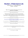
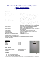
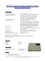
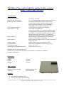
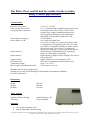
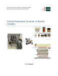
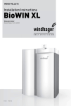
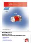
Automatic Blow-Clear Equipment Version 3.1-3.4 Protected Version 2008 Hacker & Petermann GmbH Sonnengasse 13, A-9020 Klagenfurt tel:+43 (0) 463264527, fax:+43 (0) 463/913706 mobile:+43 (0) 676/845435, ext.100/200 e-mail: [email protected] www.hacker-petermann.at UID: ATU 57917927 Copyright © 2008 Hacker & Petermann Ltd Bluefly- Freiblaseinrichtung. All rights reserved. Hacker & Petermann Ltd reserve the right to change or to withdraw features offered without advance notice Hacker & Petermann Ltd. Sonnengasse 13, A-9020 Klagenfurt Austria - Carinthia Thank you for your purchase and for placing your trust in our Bluefly Blow-Clear Equipment For economic and technological reasons modern-day fire prevention often involves using smoke in-take systems to detect fire. Unfortunately these generally very good systems come with a costly disadvantage. Because air is sucked in through the pipe system inlets, fine dust is sucked in too. After a period of some months - depending on the environment - this fine dust clogs the inlets. Besides leading to a breakdown in the smoke in-take system, this could even result in a fire being detected too late, or not at all. It is because of breakdowns in the smoke in-take system that pipe system maintenance and cleaning usually come at such a high cost. With our BLUFLY Blow-Clear System you can say goodbye to maintenance and cleaning costs - and to increased risks! Once installed, Blow-Clear uses compressed air to clean the pipe system, fully automatically and at intervals of your choosing. The comparatively low purchase price will be repaid in no time because of the savings you make on the costs of breakdowns. If you are interested, or you have got questions or improvement suggestions, or queries, please contact us in person, or on the telephone numbers given above. We will be pleased to give you advice. We are available at any time on the following mobile number: +43 (0) 676/845435, ext.100/200 Copyright © 2008 Hacker & Petermann Ltd Bluefly- Freiblaseinrichtung. All rights reserved. Hacker & Petermann Ltd reserve the right to change or to withdraw features offered without advance notice The automatic Blow-Clear control unit Type 3.1 for smoke in-take systems, using 1 sensor pipe network Technical data: Electrical connection: Valves to the suction side: Compressed air connection: Sensor pipe/suction pipe: Reset contact 1 A/B: Input contact 1a: Input contact 2: Output contact: Protection class: Temperature range: Max. height of installation location: 230 V AC, 1.5 mm2 G 1“ for minimal and negligible intake pressure loss Internal pressure reducer, max. 10 bar oil-free pressured air, using a standard compressed-air quick-coupling. Working pressure adjustable depending on sensor pipe length max. 5 bar. 25 mm plastics connection for bonding. N/O contact, potential free. Closes for a second, every time before and/or after or during blow-clearing takes place. This is so that, provided it is compatible with the air intake system, the error message “low air flow” is suppressed during blow-clearing, or for cleaning is deactivated. Input contact for unscheduled blow-clearing by means of a SIS signal, or manually. Input contact to suppress blow-clearing if fire alert is detected by SIS. Output contact for error messages to SIS. IP65 with a transparent control element cover. from +5 to +45 °C. 2500 m above sea level Distance between sensor pipes 10cm. Suitable for use only inside buildings with standard environmental conditions. No acidic ambient air. Dimensions: Width: Height: Breadth: 350 mm 450 mm 150 mm Timer control: Number of blow-clearing: Time slice: standard 6 times a day freely adjustable Optional: Case made of stainless steel Internal adjustable cabinet heating Copyright © 2008 Hacker & Petermann Ltd Bluefly- Freiblaseinrichtung. All rights reserved. Hacker & Petermann Ltd reserve the right to change or to withdraw features offered without advance notice The Blow-Clear control unit for smoke in-take systems, using 2 sensor pipe network Technical data: Electrical connection: Valves to the suction side: Compressed air connection: Sensor pipe/suction pipe: Reset contact 1 A/B: Input contact 1a: Input contact 2: Output contact: Protection class: Temperature range: Max. height of installation location: 230 V AC, 1.5 mm2 G 1“ for minimal and negligible intake pressure loss Internal pressure reducer, max. 10 bar oil-free pressured air, using a standard compressed-air quick-coupling. Working pressure adjustable depending on sensor pipe length max. 5 bar. 25 mm plastics connection for bonding. N/O contact, potential free. Closes for a second, every time before and/or after or during blow-clearing takes place. This is so that, provided it is compatible with the air intake system, the error message “low air flow” is suppressed during blow-clearing, or for cleaning is deactivated. Input contact for unscheduled blow-clearing by means of a SIS signal, or manually. Input contact to suppress blow-clearing if fire alert is detected by SIS. Output contact for error messages to SIS. IP65 with a transparent control element cover. from +5 to +45 °C. 2500 m above sea level Distance between sensor pipes 10cm. Suitable for use only inside buildings with standard environmental conditions. No acidic ambient air. Dimensions: Width: Height: Breadth: 700 mm 500 mm 150 mm Timer control: Number of blow-clearing: Time slice: standard 6 times a day freely adjustable Optional: Case made of stainless steel Internal adjustable cabinet heating Copyright © 2008 Hacker & Petermann Ltd Bluefly- Freiblaseinrichtung. All rights reserved. Hacker & Petermann Ltd reserve the right to change or to withdraw features offered without advance notice The Blow-Clear control unit for smoke in-take systems, using 3 sensor pipe network Technical data: Electrical connection: Valves to the suction side: Compressed air connection: Sensor pipe/suction pipe: Reset contact 1 A/B: Input contact 1a: Input contact 2: Output contact: Protection class: Temperature range: Max. height of installation location: 230 V AC, 1.5 mm2 G 1“ for minimal and negligible intake pressure loss Internal pressure reducer, max. 10 bar oil-free pressured air, using a standard compressed-air quick-coupling. Working pressure adjustable depending on sensor pipe length max. 5 bar. 25 mm plastics connection for bonding. N/O contact, potential free. Closes for a second, every time before and/or after or during blow-clearing takes place. This is so that, provided it is compatible with the air intake system, the error message “low air flow” is suppressed during blow-clearing, or for cleaning is deactivated. Input contact for unscheduled blow-clearing by means of a SIS signal, or manually. Input contact to suppress blow-clearing if fire alert is detected by SIS. Output contact for error messages to SIS. IP65 with a transparent control element cover. from +5 to +45 °C. 2500 m above sea level Distance between sensor pipes 10cm. Suitable for use only inside buildings with standard environmental conditions. No acidic ambient air. Dimensions: Width: Height: Breadth: 700 mm 500 mm 150 mm Timer control: Number of blow-clearing: Time slice: standard 6 times a day freely adjustable Optional: Case made of stainless steel Internal adjustable cabinet heating Copyright © 2008 Hacker & Petermann Ltd Bluefly- Freiblaseinrichtung. All rights reserved. Hacker & Petermann Ltd reserve the right to change or to withdraw features offered without advance notice The Blow-Clear control unit for smoke in-take systems, using 4 sensor pipe network Technical data: Electrical connection: Valves to the suction side: Compressed air connection: Sensor pipe/suction pipe: Reset contact 1 A/B: Input contact 1a: Input contact 2: Output contact: Protection class: Temperature range: Max. height of installation location: 230 V AC, 1.5 mm2 G 1“ for minimal and negligible intake pressure loss Internal pressure reducer, max. 10 bar oil-free pressured air, using a standard compressed-air quick-coupling. Working pressure adjustable depending on sensor pipe length max. 5 bar. 25 mm plastics N/O contact, potential free. Closes for a second, every time before and/or after or during blow-clearing takes place. This is so that, provided it is compatible with the air intake system, the error message “low air flow” is suppressed during blow-clearing, or for cleaning is deactivated. Input contact for unscheduled blow-clearing by means of a SIS signal, or manually. Input contact to suppress blow-clearing if fire alert is detected by SIS. Output contact for error messages to SIS. IP65 with a transparent control element cover. from +5 to +45 °C. 2500 m above sea level Distance between sensor pipes 10cm. Suitable for use only inside buildings with standard environmental conditions. No acidic ambient air. Dimensions: Width: Height: Breadth: 700 mm 500 mm 150 mm Timer control: Number of blow-clearing: Time slice: standard 6 times a day freely adjustable Optional: Case made of stainless steel Internal adjustable cabinet heating Copyright © 2008 Hacker & Petermann Ltd Bluefly- Freiblaseinrichtung. All rights reserved. Hacker & Petermann Ltd reserve the right to change or to withdraw features offered without advance notice Technical User Manual for Blow-Clear Equipment: For all technical questions ask your reseller or Mr. Markus Petermann from Hacker & Petermann GmbH support on phone number : 0043 (0) 676 845435 200 Installation: The Blow-Clear system must be installed between your smoke in-take system and the pipe network. More specifically, the Blow-Clear apparatus should be installed immediately behind the smoke in-take system. We suggest to install possible filter etc. between the SIS and our automatic Blow-Clear-System, because this components could be damages by the pressured air. Ask your filter supplier for more information. We recommend to fix our system firmly onto the wall, using dowels and screws. You should use the prepared four holes. Especially by the IP 65 model we advise the usage of screws with sealings. The Blow-Clear-System should be connected with the standard plastic pipes of your smoke in-take system. Please open the plastic screwing 1* of the lower “suction pipe” and on the upper “sensor pipe” and push the plastic pipes of your SIS through the provided holes *2. Than glue the pipes sealed with your standard adhesive into the pipe coupling *3. By screwing down the plastic screws *1 after the adhesive is cured the case will be sealed. The compressed-air quick release coupling *4 must be connected with oil-free compressed air of between 2 and max. 10 bar. Make sure that the compressed air supply is sufficient. Copyright © 2008 Hacker & Petermann Ltd Bluefly- Freiblaseinrichtung. All rights reserved. Hacker & Petermann Ltd reserve the right to change or to withdraw features offered without advance notice Electrical connections: As the cable entry *5 is situated at the bottom, the system can be connected to the mains supply as well as to the smoke intake system, if necessary. The Bluefly Blow-Clear System operates on an alternating current of 230 volts. Connect up to the terminals as follows: Live (black), Neutral (blue), Protective Earth (green/yellow). The in- and output contacts will be connected depending on programming. Further information you can find in the circuit diagrams. Adjust the internal pressure reducer: In order to save you further costs, our new automatic blow clear system has a serial pressure reducer with a manometer *6. This one allows you to reduce the standard pressure of your pressured air supply with about 810 bar to the optimal working pressure. We advise to begin with a pressure of approximately 2 bar and to increase pressure depending on sensor pipe length. Maximal pressure should be 5 bar, because you loose warranty of valves with higher pressures. Attention: Our new automatic blow clear system type 3 contain ¼” pressure valves, which allows a higher air flow with the same working pressure. So the pressure and the airflow has to be adjusted with the pressure reducer. Copyright © 2008 Hacker & Petermann Ltd Bluefly- Freiblaseinrichtung. All rights reserved. Hacker & Petermann Ltd reserve the right to change or to withdraw features offered without advance notice Included: Protection class IP65 with folding upwards control element cover for better protection against water, dust and contact to electrical parts. Internal pressure reducer with manometer: This one allows you to reduce the standard pressure of your pressured air supply with about 8-10 bar to the optimal working pressure. We advise to begin with a pressure of approximately 2 bar and to increase pressure depending on sensor pipe length. Maximal pressure should be 5 bar, because you loose warranty of valves with higher pressures. Attention: Our new automatic blow clear system type 3 contain ¼” pressure valves, which allows a higher air flow with the same working pressure. So the pressure and the airflow has to be adjusted with the pressure reducer. Input contact for unscheduled blow-clearing by means of an SIS signal, or manually by installed button. Here, an input contact I1 is installed, which activates the blowclearing in case the signal (e.g. of the smoke intake system) is not available (e.g. error message “line blocked“). Input contact for suppressing a blow-clearing if a fire alert is detected by SIS while clearing should happen by schedule. Output contact for error message. Here, an output contact O1&2 (NO switch) is installed that can for instance – depending on the programming – signal that, after unscheduled blow-clearing, the SIS input signal (e.g. error message “line blocked“) is still not activated. Copyright © 2008 Hacker & Petermann Ltd Bluefly- Freiblaseinrichtung. All rights reserved. Hacker & Petermann Ltd reserve the right to change or to withdraw features offered without advance notice Optional: Case made of stainless Steel for bad environmental conditions/ recommended by law or just for a better design. Equipment cabinet heating To protect the technical equipment against lower temperatures, etc, a pre-assembled equipment cabinet heating is available. It can be readily integrated into the Blow-Clear System. Setting the Blow-Clearing Intervals & Programming: Bluefly Blow-Clear Systems are delivered factory-adjusted to meet the customer’s requirements. Only the time setting for the blow-clearing has to be changed, if necessary. If you want to set the blow clearing times you need the Logo Soft 5 software and a data cable. In the supplied control program you only are allowed to set the two timers on the upper left side. Double-click on the timer and change the “Nocken” 1-3 (your blow-clearing times) analog to the old one. That means from 07:00 and 07:01 you can make 14:30 and 14:31. The one minute delay is only for the program. All changes in software have to be made by professional personal. Consequential damages are excluded from any possible warranty or liability claim. For any further information please contact us on the telephone numbers given before. Copyright © 2008 Hacker & Petermann Ltd Bluefly- Freiblaseinrichtung. All rights reserved. Hacker & Petermann Ltd reserve the right to change or to withdraw features offered without advance notice Operation mode of the Bluefly Blow-Clear Equipment: Once it has been assembled according to the instructions and connected to the mains, Bluefly Blow-Clear Equipment is ready for operation. Under normal operating conditions for smoke detection, the air from the sensor pipe network is sucked through our Blow-Clear System into the smoke in-take system. In order to minimise loss of intake pressure because of the flow resistance of valves, we only use top-quality 1 inch magnetic valves. Tests undertaken by a leading manufacturer of smoke in-take systems have shown that loss of intake pressure is in fact negligible. In its stand-by state, oil-free compressed air (which is connected to our system by means of customer-friendly standard couplings) is drawn into the internal pressure reducer. With the pressure reducer you have to adjust the working pressure. Then the pressured air drawn into compressed-air valves. For each sensor pipe line we use a separate compressed-air valve to avoid increasing the quantity of air that has to be supplied by the compressor. The air flow depends on sensor pipe length and number of suction holes and is about 200-350 liter per minute. During clearing, the 1-inch valves close the suction line. In this way, the SIS is separated from the sensor pipe network. When the suction line is closed, we can make this known to the smoke intake system, provided it is compatible, by momentarily closing the A&B1 message contact, in order to suppress the error message “low air flow“, or to deactivate it during blowclearing. After a short delay the first compressed-air valve opens again and compressed air is allowed to flow through the first sensor pipe, for 20 to 30 seconds. Thus, the network can be blowcleared of precipitates. Afterwards the compressed-air valve closes again and the process is repeated for each sensor pipe line. When the compressed-air valve is closed, the 1-inch valve to the suction pipes opens again and the SIS again sucks air from the cleaned sensor pipe network. This resetting of normal operating conditions is marked by A&B1 message contact closing for one second to ensure that the SIS remains enabled. Depending on the programming, this procedure can be repeated up to six times, at set times. Copyright © 2008 Hacker & Petermann Ltd Bluefly- Freiblaseinrichtung. All rights reserved. Hacker & Petermann Ltd reserve the right to change or to withdraw features offered without advance notice