1
Ion Max
APPI Source
User Manual
97055-97021 Revision C
February 2009
© 2009 Thermo Fisher Scientific Inc. All rights reserved.
TSQ is a registered trademark of Thermo Fisher Scientific Inc. in the United States. LCQ, LTQ and Ion Max
are trademarks of Thermo Fisher Scientific Inc. PhotoMate is a trademark of Syagen Technology Inc. Swagelok
is a registered trademark of the Crawford Fitting Company. Teflon is a registered trademark of E. I. du Pont de
Nemours & Co.
Thermo Fisher Scientific Inc. provides this document to its customers with a product purchase to use in the
product operation. This document is copyright protected and any reproduction of the whole or any part of this
document is strictly prohibited, except with the written authorization of Thermo Fisher Scientific Inc.
The contents of this document are subject to change without notice. All technical information in this
document is for reference purposes only. System configurations and specifications in this document supersede
all previous information received by the purchaser.
Thermo Fisher Scientific Inc. makes no representations that this document is complete, accurate or errorfree and assumes no responsibility and will not be liable for any errors, omissions, damage or loss that might
result from any use of this document, even if the information in the document is followed properly.
This document is not part of any sales contract between Thermo Fisher Scientific Inc. and a purchaser. This
document shall in no way govern or modify any Terms and Conditions of Sale, which Terms and Conditions of
Sale shall govern all conflicting information between the two documents.
Release history: Revision C in February 2009. Revision B in June 2006. Revision A in September
2003.
Software version: Xcalibur 2.0
For Research Use Only. Not regulated for medical or veterinary diagnostic use by U.S. Federal Drug
Administration or other competent authorities.
Regulatory Compliance
Thermo Fisher Scientific performs complete testing and evaluation of its products to ensure full compliance with
applicable domestic and international regulations. For more information, refer to manual for your Thermo Scientific
mass spectrometer.
Changes that you make to your system might void compliance with one or more of these EMC and safety standards.
Changes to your system include replacing a part or adding components, options, or peripherals not specifically
authorized and qualified by Thermo Fisher Scientific. To ensure continued compliance with EMC and safety standards,
replacement parts and additional components, options, and peripherals must be ordered from Thermo Fisher Scientific
or one of its authorized representatives.
FCC Compliance Statement
THIS DEVICE COMPLIES WITH PART 15 OF THE FCC RULES. OPERATION IS SUBJECT TO
THE FOLLOWING TWO CONDITIONS: (1) THIS DEVICE MAY NOT CAUSE HARMFUL
INTERFERENCE, AND (2) THIS DEVICE MUST ACCEPT ANY INTERFERENCE RECEIVED,
INCLUDING INTERFERENCE THAT MAY CAUSE UNDESIRED OPERATION.
CAUTION Read and understand the various precautionary notes, signs, and symbols contained inside
this manual pertaining to the safe use and operation of this product before using the device.
Notice on the Proper Use of
Thermo Scientific Instruments
In compliance with international regulations: Use of this instrument in a manner not specified by Thermo Fisher
Scientific could impair any protection provided by the instrument.
Notice on the Susceptibility
to Electromagnetic Transmissions
Your instrument is designed to work in a controlled electromagnetic environment. Do not use radio frequency
transmitters, such as mobile phones, in close proximity to the instrument.
For manufacturing location, see the label on the instrument.
WEEE Compliance
This product is required to comply with the European Union’s Waste Electrical & Electronic
Equipment (WEEE) Directive 2002/96/EC. It is marked with the following symbol:
Thermo Fisher Scientific has contracted with one or more recycling or disposal companies in each
European Union (EU) Member State, and these companies should dispose of or recycle this product.
See www.thermo.com/WEEERoHS for further information on Thermo Fisher Scientific’s compliance
with these Directives and the recyclers in your country.
WEEE Konformität
Dieses Produkt muss die EU Waste Electrical & Electronic Equipment (WEEE) Richtlinie 2002/96/EC
erfüllen. Das Produkt ist durch folgendes Symbol gekennzeichnet:
Thermo Fisher Scientific hat Vereinbarungen mit Verwertungs-/Entsorgungsfirmen in allen EUMitgliedsstaaten getroffen, damit dieses Produkt durch diese Firmen wiederverwertet oder entsorgt
werden kann. Mehr Information über die Einhaltung dieser Anweisungen durch Thermo Fisher
Scientific, über die Verwerter, und weitere Hinweise, die nützlich sind, um die Produkte zu
identifizieren, die unter diese RoHS Anweisung fallen, finden sie unter www.thermo.com/
WEEERoHS.
Conformité DEEE
Ce produit doit être conforme à la directive européenne (2002/96/EC) des Déchets d'Equipements
Electriques et Electroniques (DEEE). Il est marqué par le symbole suivant:
Thermo Fisher Scientific s'est associé avec une ou plusieurs compagnies de recyclage dans chaque état
membre de l’union européenne et ce produit devrait être collecté ou recyclé par celles-ci. Davantage
d'informations sur la conformité de Thermo Fisher Scientific à ces directives, les recycleurs dans votre
pays et les informations sur les produits Thermo Fisher Scientific qui peuvent aider la détection des
substances sujettes à la directive RoHS sont disponibles sur www.thermo.com/WEEERoHS.
CAUTION Symbol
CAUTION
VORSICHT
ATTENTION
PRECAUCION
AVVERTENZA
Electric Shock: This instrument uses
high voltages that can cause personal
injury. Before servicing, shut down the
instrument and disconnect the instrument
from line power. Keep the top cover on
while operating the instrument. Do not
remove protective covers from PCBs.
Elektroschock: In diesem Gerät werden
Hochspannungen verwendet, die
Verletzungen verursachen können. Vor
Wartungsarbeiten muß das Gerät
abgeschaltet und vom Netz getrennt
werden. Betreiben Sie Wartungsarbeiten
nicht mit abgenommenem Deckel. Nehmen
Sie die Schutzabdeckung von Leiterplatten
nicht ab.
Choc électrique: L’instrument utilise des
tensions capables d’infliger des blessures
corprelles. L’instrument doit être arrêté et
débranché de la source de courant avant
tout intervention. Ne pas utiliser
l’instrument sans son couvercle. Ne pas
elensver les étuis protecteurs des cartes de
circuits imprimés.
Descarga eléctrica: Este instrumento
utiliza altas tensiones, capaces de
producir lesiones personales. Antes de
dar servicio de mantenimiento al
instrumento, éste debera apagarse y
desconectarse de la línea de alimentacion
eléctrica. No opere el instrumento sin sus
cubiertas exteriores quitadas. No remueva
las cubiertas protectoras de las tarjetas
de circuito impreso.
Shock da folgorazione. L’apparecchio è
alimentato da corrente ad alta tensione
che puo provocare lesioni fisiche. Prima di
effettuare qualsiasi intervento di
manutenzione occorre spegnere ed isolare
l’apparecchio dalla linea elettrica. Non
attivare lo strumento senza lo schermo
superiore. Non togliere i coperchi a
protezione dalle schede di circuito
stampato (PCB).
Chemical: This instrument might contain
hazardous chemicals. Wear gloves when
handling toxic, carcinogenic, mutagenic,
or corrosive or irritant chemicals. Use
approved containers and proper
procedures to dispose waste oil.
Chemikalien: Dieses Gerät kann
gefährliche Chemikalien enthalten. Tragen
Sie Schutzhandschuhe beim Umgang mit
toxischen, karzinogenen, mutagenen oder
ätzenden/reizenden Chemikalien.
Entsorgen Sie verbrauchtes Öl
entsprechend den Vorschriften in den
vorgeschriebenen Behältern.
Chimique: Des produits chemiques
dangereux peuven se trouver dans
l’instrument. Proted dos gants pour
manipuler tous produits chemiques
toxiques, cancérigènes, mutagènes, ou
corrosifs/irritants. Utiliser des récipients
et des procédures homologuées pour se
débarrasser des déchets d’huile.
Química: El instrumento puede contener
productos quimicos peligrosos. Utilice
guantes al manejar productos quimicos
tóxicos, carcinogenos, mutagenos o
corrosivos/irritantes. Utilice recipientes y
procedimientos aprobados para
deshacerse del aceite usado.
Prodotti chimici. Possibile presenza di
sostanze chimiche pericolose
nell’apparecchio. Indossare dei guanti per
maneggiare prodotti chimici tossici,
cancerogeni, mutageni, o
corrosivi/irritanti. Utilizzare contenitori
aprovo e seguire la procedura indicata per
lo smaltimento dei residui di olio.
Heat: Before servicing the instrument,
allow any heated components to cool.
Hitze: Warten Sie erhitzte Komponenten
erst nachdem diese sich abgekühlt haben.
Haute Temperature: Permettre aux
composants chauffés de refroidir avant
tout intervention.
Altas temperaturas: Permita que lop
componentes se enfríen, ante de efectuar
servicio de mantenimiento.
Calore. Attendere che i componenti
riscaldati si raffreddino prima di
effetturare l’intervento di manutenzione.
Fire: Use care when operating the system
in the presence of flammable gases.
Feuer: Beachten Sie die einschlägigen
VorsichtsmaBnahmen, wenn Sie das
System in Gegenwart von entzündbaren
Gasen betreiben.
Incendie: Agir avec précaution lors de
l’utilisation du système en présence de
gaz inflammables.
Fuego: Tenga cuidado al operar el
sistema en presencia de gases
inflamables.
Incendio. Adottare le dovute precauzioni
quando si usa il sistema in presenza di gas
infiammabili.
Eye Hazard: Eye damage could occur
from splattered chemicals or flying
particles. Wear safety glasses when
handling chemicals or servicing the
instrument.
Verletzungsgefahr der Augen:
Verspritzte Chemikalien oder kleine
Partikel können Augenverletzungen
verursachen. Tragen Sie beim Umgang mit
Chemikalien oder bei der Wartung des
Gerätes eine Schutzbrille.
Danger pour les yeux: Dex projections
chimiques, liquides, ou solides peuvent
être dangereuses pour les yeux. Porter des
lunettes de protection lors de toute
manipulationde produit chimique ou pour
toute intervention sur l’instrument.
Peligro par los ojos: Las salicaduras de
productos químicos o particulas que
salten bruscamente pueden causar
lesiones en los ojos. Utilice anteojos
protectores al mnipular productos
químicos o al darle servicio de
mantenimiento al instrumento.
Pericolo per la vista. Gli schizzi di
prodotti chimici o delle particelle presenti
nell’aria potrebbero causare danni alla
vista. Indossare occhiali protettivi quando
si maneggiano prodotti chimici o si
effettuano interventi di manutenzione
sull’apparecchio.
General Hazard: A hazard is present that
is not included in the above categories.
Also, this symbol appears on the
instrument to refer the user to instructions
in this manual.
Allgemeine Gefahr: Es besteht eine
weitere Gefahr, die nicht in den
vorstehenden Kategorien beschrieben ist.
Dieses Symbol wird im Handbuch
auBerdem dazu verwendet, um den
Benutzer auf Anweisungen hinzuweisen.
Danger général: Indique la présence
d;un risque n’appartenant pas aux
catégories citées plus haut. Ce symbole
figure également sur l’instrument pour
renvoyer l’utilisateur aux instructions du
présent manuel.
Peligro general: Significa que existe un
peligro no incluido en las categorias
anteriores. Este simbolo también se utiliza
en el instrumento par referir al usuario a
las instrucciones contenidas en este
manual.
Pericolo generico. Pericolo non
compreso tra le precedenti categorie.
Questo simbolo è utilizzato inoltre
sull’apparecchio per segnalare all’utente
di consultare le istruzioni descritte nel
presente manuale.
When the safety of a procedure is
questionable, contact your local Technical
Support organization for Thermo Fisher
Scientific San Jose Products.
Wenn Sie sich über die Sicherheit eines
Verfahrens im unklaren sind, setzen Sie
sich, bevor Sie fortfahren, mit Ihrer
lokalen technischen
Unterstützungsorganisation für Thermo
Fisher Scientific San Jose Produkte in
Verbindung.
Si la sûreté d’un procédure est incertaine,
avant de continuer, contacter le plus
proche Service Clientèle pour les produits
de Thermo Fisher Scientific San Jose.
Cuando la certidumbre acerca de un
procedimiento sea dudosa, antes de
proseguir, pongase en contacto con la
Oficina de Asistencia Tecnica local para
los productos de Thermo Fisher Scientific
San Jose.
Quando e in dubbio la misura di sicurezza
per una procedura, prima di continuare, si
prega di mettersi in contatto con il
Servizio di Assistenza Tecnica locale per i
prodotti di Thermo Fisher Scientific San
Jose.
CAUTION Symbol
CAUTION
Electric Shock: This instrument uses
high voltages that can cause personal
injury. Before servicing, shut down the
instrument and disconnect the instrument
from line power. Keep the top cover on
while operating the instrument. Do not
remove protective covers from PCBs.
Chemical: This instrument might contain
hazardous chemicals. Wear gloves when
handling toxic, carcinogenic, mutagenic,
or corrosive or irritant chemicals. Use
approved containers and proper
procedures to dispose waste oil.
Heat: Before servicing the instrument,
allow any heated components to cool.
Fire: Use care when operating the system
in the presence of flammable gases.
Eye Hazard: Eye damage could occur
from splattered chemicals or flying
particles. Wear safety glasses when
handling chemicals or servicing the
instrument.
General Hazard: A hazard is present that
is not included in the above categories.
Also, this symbol appears on the
instrument to refer the user to instructions
in this manual.
When the safety of a procedure is
questionable, contact your local Technical
Support organization for Thermo Fisher
Scientific San Jose Products.
Contents
Preface ............................................................................................. xi
Safety and Special Notices..........................................................xi
Contacting Us...........................................................................xii
Thermo Scientific
Chapter 1
Introduction..........................................................................................1
Atmospheric Pressure Chemical Ionization .................................3
Atmospheric Pressure Photoionization ........................................6
Combined APCI and APPI .........................................................9
What Types of Buffers Should I Use? What Types Should I
Avoid? ....................................................................................10
How Should I Set Up the Mass Spectrometer for Various LC
Flow Rates? ............................................................................11
Chapter 2
Functional Description.....................................................................13
APCI Source .............................................................................14
PhotoMate Light Source ...........................................................17
Chapter 3
Setting Up the Ion Source for Acquiring Data in
APCI/APPI/MS/MS Mode23
Removing the ESI Probe ...........................................................24
Removing the Ion Max Ion Source Housing .............................26
Installing the APCI Probe .........................................................27
Installing the PhotoMate Light Source......................................30
Installing the Ion Max Ion Source Housing ..............................33
Chapter 4
Optimizing the LCQ Deca XP MAX MS Detector with Your
Analyte37
Setting Up the Inlet for Tuning Using High-Flow Infusion ......38
Setting Up the MS Detector for APCI/APPI/MS Operation.....42
Optimizing the Tune of the MS Detector Automatically in
APCI/APPI/MS Mode ...........................................................45
Saving the Tune Method ..........................................................47
Cleaning the MS Detector After Tuning in APCI Mode...........49
Chapter 5
Optimizing the LTQ MS Detector with Your Analyte ..................51
APPI Souce User Manual
ix
Contents
Setting Up the Inlet for Tuning Using High-Flow Infusion ......52
Setting Up the MS Detector for APCI/APPI/MS Operation.....55
Optimizing the Tune of the MS Detector Automatically in
APCI/APPI/MS Mode ...........................................................58
Saving the APCI/APPI/MS Tune Method ................................61
Cleaning the MS Detector After Tuning in APCI Mode...........63
Chapter 6
Optimizing the TSQ Quantum Ultra Mass Spectrometer with
Your Analyte65
Setting Up to Introduce Sample by Auto Loop Injection
in APCI Mode ..........................................................................67
Setting Up to Optimize in APCI/APPI/MS/MS
Mode with Your Compound.....................................................71
Optimizing in APCI/APPI/MS/MS Mode
Automatically with Your Compound ........................................77
Saving the Tune Method ..........................................................82
Cleaning the Mass Spectrometer After Tuning
in APCI Mode ..........................................................................84
Chapter 7
Maintenance ..................................................................................... 87
Maintaining the APCI Probe ....................................................88
Maintaining the PhotoMate Light Source .................................92
Cleaning and Polishing the Window of the VUV Lamp ........92
Replacing the VUV Lamp......................................................95
Chapter 8
Replaceable Parts ............................................................................ 99
Appendix A Installing the PhotoMate Light Source Adapter Ring.............. 103
Appendix B Reserpine Solution Formulations................................................ 109
Reserpine Stock Solution ........................................................111
LCQ Deca XP MAX Reserpine Sample Solution ....................112
LTQ Reserpine Sample Solution.............................................113
TSQ Quantum Ultra Reserpine Sample Solution....................114
Index ................................................................................................. 115
x
APPI Souce User Manual
Thermo Scientific
P
Preface
This guide describes how to set up and install the PhotoMate® light source on the Ion
Max ion source housing with an APCI probe. It also describes how to optimize the
tune of your instrument after you have installed the Ion Max APPI source.
Safety and Special Notices
Make sure you follow the precautionary statements presented in this guide. The safety and
other special notices appear in boxes.
Safety and special notices include the following:
CAUTION Highlights hazards to humans, property, or the environment. Each CAUTION
notice is accompanied by an appropriate CAUTION symbol.
IMPORTANT Highlights information necessary to prevent damage to software, loss of
data, or invalid test results; or might contain information that is critical for optimal
performance of the system.
Note Highlights information of general interest.
Tip Highlights helpful information that can make a task easier.
Thermo Scientific
APPI Source User Manual
xi
Preface
Contacting Us
Contacting Us
There are several ways to contact Thermo Fisher Scientific for the information you need.
Y To contact Technical Support
Phone
800-532-4752
Fax
561-688-8736
E-mail
[email protected]
Knowledge base
www.thermokb.com
Find software updates and utilities to download at mssupport.thermo.com.
Y To contact Customer Service for ordering information
Phone
800-532-4752
Fax
561-688-8731
E-mail
[email protected]
Web site
www.thermo.com/ms
Y To copy manuals from the Internet
Go to mssupport.thermo.com and click Customer Manuals in the left margin of the
window.
Y To suggest changes to documentation or to Help
Send an e-mail message to the Technical Publications Editor at
[email protected].
xii
APPI Source User Manual
Thermo Scientific
Chapter 1
Introduction
The Ion Max™ ion source is a member of the Thermo Scientific family of
mass spectrometer ion sources.
Your Ion Max APCI/APPI combination probe allows you to perform
successful qualitative and quantitative analysis on a wide range of
compounds, including steroids, peptides, basic drug entities, and pesticides.
You can use APPI and APCI to study compounds that are not readily
ionized by electrospray ionization (ESI). See Figure 1.
You can operate your APCI/APPI combination probe using the following
ionization techniques:
• Atmospheric pressure chemical ionization (APCI)
• Atmospheric pressure photoionization (APPI)
• Combined APCI and APPI
Thermo Scientific
APPI Souce User Manual
1
1
Introduction
10,000
ESI
1,000
APPI
MW
APCI
100
10
Nonpolar
Ionic
Polarity
Figure 1.
2
Ranges of applicability of APPI, APCI, and ESI
APPI Souce User Manual
Thermo Scientific
1 Introduction
Atmospheric Pressure Chemical Ionization
Atmospheric Pressure
Chemical Ionization
Atmospheric pressure chemical ionization (APCI) is a soft ionization
technique, but not as soft as ESI. APCI is used to analyze compounds of
medium polarity that have some volatility.
In APCI, ions are produced and analyzed as follows:
1. The APCI nozzle sprays the sample solution into a fine mist of droplets.
2. The droplets are vaporized in a high temperature tube (the vaporizer).
3. A high voltage is applied to a needle located near the exit end of the
tube. The high voltage creates a corona discharge that forms reagent ions
through a series of chemical reactions with solvent molecules and
nitrogen sheath gas.
4. The reagent ions react with sample molecules to form sample ions.
5. The sample ions enter the mass spectrometer and are analyzed.
Figure 1 shows the APCI process for positive adduct ion formation.
APCI is a gas phase ionization technique. Therefore, the gas phase acidities
and basicities of the analyte and solvent vapor play an important role in the
APCI process.
In the positive-ion mode, sample ionization occurs in a series of reactions
that start with the electron-initiated cation formation. Typical examples of
primary, secondary, and adduct ion formation are shown below:
Primary ion formation
e- + N2 → N2+. + 2eSecondary ion formation
N2+. + H2O → N2 + H2O+.
H2O+. + H2O → H3O+ + HO.
Proton transfer
H3O+ + M → (M + H)+ + H2O
In negative-ion mode, (M − H)- is typically formed by the abstraction of a
proton by OH-.
Thermo Scientific
APPI Souce User Manual
3
1
Introduction
Atmospheric Pressure Chemical Ionization
APCI is typically used to analyze small molecules with molecular weights up
to about 1500 u. APCI is a very robust ionization technique. It is not
affected by minor changes in most variables, such as changes in buffers or
buffer strength.
APCI Nozzle
Atmospheric
Pressure
Region
CI
AP
Pr
+10 V
e
ob
Ion Sweep
Cone
Pressure
= 1 Torr
Ion
Transfer
Capillary
Chemical
Ionization
M
S SM
SM M S
SMSMSM
H O+
SS
3
(M+H) +
HO
2
Corona
Discharge
Needle
(+3 TO +5 kV)
H 20+
H 20
Corona
Discharge
Needle
(+3 TO +5 kV)
H 20+
+
++ +
++
Figure 2.
H 20+
H 20+
e e
N2+ e-
Corona
Discharge
Region
(Plasma)
N 2+
N 2+
N 2+e
APCI process in the positive ion polarity mode
You can use APCI in positive or negative ion polarity mode. For most
molecules, the positive-ion mode produces a stronger ion current. This is
especially true for molecules with one or more basic nitrogen (or other basic)
atoms. An exception to the general rule is that molecules with acidic sites,
such as carboxylic acids and acid alcohols, produce more negative ions than
positive ions.
4
APPI Souce User Manual
Thermo Scientific
1 Introduction
Atmospheric Pressure Chemical Ionization
Although, in general, fewer negative ions are produced than positive ions,
negative ion polarity is sometimes the mode of choice. This is because the
negative ion polarity mode sometimes generates less chemical noise than
does the positive mode. Thus, selectivity might be better in the negative ion
mode than in the positive ion mode.
Thermo Scientific
APPI Souce User Manual
5
1
Introduction
Atmospheric Pressure Photoionization
Atmospheric Pressure
Photoionization
Atmospheric pressure photoionization (APPI) is also a soft ionization
technique. In APPI an ion is generated from a molecule when it interacts
with a photon from a source of light such as the Syagen PhotoMate® light
source. APPI generates molecular ions for molecules that have an ionization
potential below the photon energy of the light being emitted by the light
source.
In APPI, ions are produced and analyzed as follows:
1. The nozzle sprays the sample solution into a fine mist of droplets.
2. The droplets are vaporized in a high temperature tube (the vaporizer).
3. The analyte molecule interacts with the light from the PhotoMate light
source. The analyte molecule M is ionized to a molecular ion M+ if the
ionization potential of the analyte is less than the photon energy hν:
4. M + hν → M+ + e−
5. In the presence of protic solvents, the analyte ion may extract a
hydrogen to form an (M + H)+ ion:
6. M+ + S → (M + H)+ + (S − H)
7. The analyte ions pass through the ion transfer capillary, enter the mass
spectrometer, and are analyzed.
Molecules including steroids, basic-drug entities, and pesticides have
ionization potentials below the threshold and protonated molecules are
generated in the LC/MS experiment. APPI reduces fragmentation because
only a small amount of energy is deposited in the molecule. Molecules such
as the nitrogen sheath and auxiliary gas and the simple solvents used for
LC/MS are not ionized because their ionization potentials are greater than
the photon energy. The result is selective ionization of analyte versus
background. See Figure 2 and Figure 3.
6
APPI Souce User Manual
Thermo Scientific
1 Introduction
Atmospheric Pressure Photoionization
Energy
Gases in air,
solvent molecules
Fragment ion
thresholds
Molecular ion
thresholds
Drugs and other
compounds
hν
Photoionization
Figure 3.
Energetics of photoionization
Agricultural
compounds
MeOH, AcCN
Chlorinated-solvents
Drugs
Steroids
H2O, CO2, O2, N2
Ionized
Not Ionized
Threshold
Figure 4.
Illustration of selective photoionization
The PhotoMate light source uses a krypton lamp that emits photons with
energies of 10.0 and 10.6 eV. Molecules with ionization potentials less than
10 eV ionize to form M+ or (M + H)+, while those with greater ionization
potentials do not. Figure 4 shows ionization potentials of typical
compounds and solvents.
Thermo Scientific
APPI Souce User Manual
7
1
Introduction
Atmospheric Pressure Photoionization
Krypton 10.0 eV, 10.6 eV
Ionization Potentials (IP)
Anthracene
Fluoranthene
Caffeine
4-Nitrotoluene
7.4 eV
7.8 eV
8.0 eV
9.5 eV
Solvent Ionization Potentials (IP)
Toluene
Acetone
8.82 eV
9.70 eV
Methanol
Acetonitrile
Water
10.85 eV
12.19 eV
12.61 eV
10.0 eV
Figure 5.
8
APPI Souce User Manual
Ionization potentials of typical compounds and solvents
Thermo Scientific
1 Introduction
Combined APCI and APPI
Combined APCI and
APPI
You can easily change between APCI, APPI, and combined APCI and APPI
techniques by turning on the corona discharge needle, the PhotoMate light
source, or both. See Table 1. You turn the light source on and off by using
the On/Off switch on the light source. You turn the corona discharge needle
on and off by using the Xcalibur software. This allows you to quickly
determine which technique yields the best ion signal.
Table 1.
Thermo Scientific
Light source and corona discharge needle status for APPI, APCI, and
combined APCI/APPI modes
Ionization Technique
PhotoMate Light
Source
Corona Discharge
Needle
APPI
On
Off
APCI
Off
On
Combined APCI and
APPI
On
On
APPI Souce User Manual
9
1
Introduction
What Types of Buffers Should I Use? What Types Should I Avoid?
What Types of Buffers
Should I Use? What
Types Should I Avoid?
Use volatile buffers, when possible, to obtain the highest performance for
your assays. Many volatile buffer solutions are available that can be used
instead of nonvolatile ones. Volatile buffer solutions can include the
following:
• Acetic acid
• Ammonium acetate
• Ammonium formate
• Ammonium hydroxide
• Triethylamine (TEA)
Many LC applications use nonvolatile buffers such as phosphate and borate
buffers. However, it’s best to avoid the use of these nonvolatile buffers with
the mass spectrometer. Nonvolatile buffers can block the capillary in the
probe and can cause salt buildup in the nozzle, compromising the integrity
of the spray.
10
APPI Souce User Manual
Thermo Scientific
1 Introduction
How Should I Set Up the Mass Spectrometer for Various LC Flow Rates?
How Should I Set Up
the Mass
Spectrometer for
Various LC Flow
Rates?
The APCI/APPI combination probe can generate ions from liquid flows1 of
50 μL/min to 2.0 mL/min. This flow range allows you to use microbore
LC, analytical LC, and semipreparative LC.
As you change the rate of flow of solvents entering the mass spectrometer,
you need to adjust several parameters. For APCI and APPI, you need to
adjust the ion transfer capillary temperature, the vaporizer temperature, and
the gas flow rates for the sheath gas and auxiliary gas.
In general, an increase in the rate of liquid flowing into the mass
spectrometer requires a higher temperature of the ion transfer capillary and
vaporizer and a higher gas flow rate.
Table 2 provides starting guidelines for operating in the APPI, APCI, or
combined APCI/APPI mode. Chapter 4, 5 or 6 (depending upon your
instrument) will help you to optimize these settings for your specific
compound.
Table 2.
Guidelines for setting operating parameters for APPI, APCI, and combined APCI/APPI modes *
LC Flow Rate
(mL/min)
Capillary
Temperature (°C)
Vaporizer
Temperature (°C)
0.2 to 2.0
Typical setting:
150 to 225
Typical setting:
400 to 550
Auxiliary Gas
(arbitrary units)
Sheath Gas (psi)
Required.
Not required, but
usually helps to reduce
solvent background
ions
Typical setting:
40 to 100
Typical setting:
0 to 20
*For
thermally labile compounds you might need to use a lower vaporizer temperature and a lower flow rate.
1
Thermo Scientific
Flows below 200 μL/min require more care to maintain a stable spray.
APPI Souce User Manual
11
Chapter 2
Functional Description
This chapter describes the principal components of the APCI/APPI
combination probe.
The APCI/APPI combination probe forms gas phase sample ions from
sample molecules that are contained in solution. You can operate the
APCI/APPI combination probe using either atmospheric pressure chemical
ionization (APCI), atmospheric pressure photoionization (APPI), or both.
The APCI/APPI combination probe includes:
• APCI Source
• PhotoMate Light Source
Thermo Scientific
APPI Souce User Manual
13
2
Functional Description
APCI Source
APCI Source
The APCI probe ionizes the sample by atmospheric pressure chemical
ionization. The APCI probe accommodates liquid flows of 100 μL/min to
2 mL/min without splitting. See Figure 6. The APCI probe includes the
APCI sample tube, nozzle, sheath gas and auxiliary gas plumbing, and
vaporizer. See Figure 7 and Figure 8. Sample and solvent enter the APCI
nozzle through the sample tube. The sample tube is a short section of 0.10
mm ID fused silica tubing that extends from the sample inlet to 1 mm past
the end of the nozzle. The manifold houses the APCI nozzle and includes
the sheath gas and auxiliary gas plumbing. The APCI nozzle sprays the
sample solution into a fine mist. The sheath gas and auxiliary gas plumbing
deliver dry nitrogen gas to the nozzle. The droplets in the mist then enter
the vaporizer. The vaporizer flash vaporizes the droplets at temperatures up
to 500 °C.
Ion Transfer
Capillary
APCI
Probe
Corona
Needle
Ion Transfer
Capillary Entrance
Figure 6.
APCI probe, showing the corona discharge needle and ion transfer
capillary
Typical vaporizer temperatures are 350 to 450 °C for flow rates of 0.1 to
2 mL/min. The sample vapor is swept toward the corona discharge needle
by the flow of the sheath and auxiliary gasses.
The corona discharge needle assembly is mounted inside of the Ion Max
API source housing. The tip of the corona discharge needle is positioned
near the vaporizer. A high potential (typically ±3 to ±5 kV) is applied to the
14
APPI Souce User Manual
Thermo Scientific
2
Functional Description
APCI Source
corona discharge needle to produce a corona discharge current of up to
100 μA. (A typical value of the corona discharge current is 5 μA.) The
corona discharge from the needle produces reagent ion plasma primarily
from the solvent vapor. The sample vapor is ionized by ion-molecule
reactions with the reagent ions in the plasma.
APCI requires a constant source of electrons for the ionization process.
Thus, the corona discharge current is set to a specific value and regulated.
The potential applied to the corona discharge needle varies, as needed, to
provide the required current.
Vaporizer
Heater Cable
Socket
APCI Nozzle
Ceramic Heater Tube
0.312 ID O-ring
0.500 ID
1/16 Viton
O-Ring
Sample
Inlet Fitting
Sample Tube
Figure 7.
Cross sectional viewof the APCI probe
Thermo Scientific
APPI Souce User Manual
15
2
Functional Description
APCI Source
Vaporizer Heater
Cable Socket
Guide Pin
Retention Flange
Flat Side
APCI Nozzle Assembly
Retention Flange
Figure 8.
16
APPI Souce User Manual
APCI probe exterior
Thermo Scientific
2
PhotoMate Light
Source
Functional Description
PhotoMate Light Source
The light source is a Syagen PhotoMate vacuum ultraviolet (VUV) light
source. The assembly is mounted on the left side of the Ion Max ion source
housing using a specially designed adapter ring.
The PhotoMate light source includes the following components. See
Figure 9 through Figure 11.
• Power supply
• Electronics PCB
• VUV lamp
• Lamp shield
• Box fan
• Lamp On/Off switch
• Safety interlocks
• Remote LEDs
• Window
Thermo Scientific
APPI Souce User Manual
17
2
Functional Description
PhotoMate Light Source
Figure 9.
18
APPI Souce User Manual
PhotoMate light source installed in the Ion Max ion source housing,
side view
Thermo Scientific
2
Functional Description
PhotoMate Light Source
Figure 10. PhotoMate light source installed in the Ion Max ion source housing,
front view
Box Fan
Electronics PCB
Lamp Shield
VUV Lamp
Figure 11. PhotoMate light source (internal components)
Thermo Scientific
APPI Souce User Manual
19
2
Functional Description
PhotoMate Light Source
The power supply provides +48 V dc power for the electronics PCB and fan.
The LTQ MS detector and TSQ Quantum Ultra mass spectrometer can
both supply this power through a DB-15 cable connection. The LTQ MS
detector is also able to control the lamp status through the connection. The
LCQ Deca XP MAX requires that this power be supplied via an external
power supply, which is also connected using the DB-15 connection.
The electronics PCB contains electronic circuitry for driving the VUV
lamp, a photodiode for detecting light emitted by the VUV lamp, and a
thermocouple for monitoring the temperature. The electronics PCB also
powers the status LEDs.
The VUV lamp is an electrodeless, quartz cell with a magnesium fluoride
window. (The window is transparent to VUV light, but the quartz is not.)
The VUV lamp is filled with krypton gas. The lamp emits radiation at
10.0 eV and 10.6 eV.
Minimize the chance of breaking the VUV lamp by doing the following:
• Always wear clean gloves when you handle the VUV lamp.
Fingerprints on the lamp can cause the lamp to fail when it is in use.
• Do not spray solvent on the VUV lamp while it is hot. The VUV
lamp can crack.
• Do not leave the LC or other liquid delivery device on while the mass
spectrometer is in Standby. The absence of sheath and auxiliary gas
can cause the hot lamp to break upon contact with liquids.
The lamp shield protects the VUV lamp.
The box fan cools the electronics PCB and prevents heat from the vaporizer
from damaging the electronics PCB. The fan draws cool air into the light
source. The fan runs at all times – even if the lamp is off.
CAUTION Never disconnect the power cord from the PhotoMate light
source or disconnect the PhotoMate power supply from line power while
the vaporizer is hot. Without power, the fan will stop running and heat
from the vaporizer could damage the electronics PCB.
The lamp On/Off switch turns on and off the power to the circuitry that
powers the VUV lamp. The box fan remains on at all times and is not
controlled by the lamp On/Off switch.
The safety interlock switch prevents the light source from operating when
not attached to the Ion Max ion source housing.
20
APPI Souce User Manual
Thermo Scientific
2
Functional Description
PhotoMate Light Source
The remote status light-emitting diode (LED) is located on the front of the
light source. The LED is illuminated green if the APPI source is connected
to an instrument that has remote control of the lamp status (the LTQ MS
detector). When the Remote LED is illuminated, the switch on the light
source is inactive and will not turn the lamp on and off. When the lamp is
not illuminated, the instrument to which it is connected has no control of
the lamp status and the lamp must be turned on and off with the switch on
the source (TSQ Quantum Ultra mass spectrometer and LCQ Deca XP
MAX MS detector).
The front window in the Ion Max ion source housing allows you to verify
that the light source is working properly. You can see purple light if the light
source is working properly. If the light is red (due to exposure to ambient
nitrogen) then the lamp is broken.
Thermo Scientific
APPI Souce User Manual
21
Chapter 3
Setting Up the Ion Source for
Acquiring Data in
APCI/APPI/MS/MS Mode
This chapter provides information on setting up the ion source for acquiring
data in the APCI/MS/MS mode.
This chapter contains the following sections:
• Removing the ESI Probe
• Removing the Ion Max Ion Source Housing
• Installing the APCI Probe
• Installing the PhotoMate Light Source
• Installing the Ion Max Ion Source Housing
Thermo Scientific
APPI Souce User Manual
23
3 Setting Up the Ion Source for Acquiring Data in APCI/APPI/MS/MS Mode
Removing the ESI Probe
Removing the ESI
Probe
To remove the ESI source
1. Place the LC/MS system in Standby:
a. Stop the flow of solvent to the ESI source.
Note The following procedures are intended for use with all systems. If
you have questions regarding the operation of your MS system, please
refer to the appropriate system-specific manuals. This might include the
Getting Started and Hardware manuals for your system. For information
on installation and maintenance of other Ion Max probes, please refer to
the Ion Max API Source Hardware Manual.
b. Turn off the ESI spray voltage.
c. Click on the On/Standby button on the toolbar to place the mass
spectrometer in Standby.
On Standby
Note If your ESI probe does not already have a sample tube (fused-silica
capillary) and safety sleeve attached, you need to follow the procedure for
installing a sample tube and PEEK safety sleeve that is outlined in the
topic Installing a New Fused-Silica Sample Tube and PEEK Safety Sleeve
in the Ion Max API Source Hardware Manual.
2. Disconnect the sample transfer tubing from the stainless steel ZDV
fitting (grounding union). See Figure 12.
3. Remove the 8 kV cable from the ESI needle high voltage receptacle as
follows: (See Figure 12.)
4. Unlock the cable by twisting the locking ring counter-clockwise.
5. Unplug the 8 kV cable from the ESI needle high voltage receptacle.
6. Disconnect the AUX Gas fitting (green) from the auxiliary gas inlet (A)
on the probe manifold. (Figure 12)
7. Disconnect the Sheath Gas fitting (blue) from the sheath gas inlet (S) on
the probe manifold.
24
APPI Souce User Manual
Thermo Scientific
3
Setting Up the Ion Source for Acquiring Data in APCI/APPI/MS/MS Mode
Removing the ESI Probe
8. Remove the stainless steel ZDV fitting (Grounding Union) from the
grounding bar on the ion source housing.
PEEK
Safety
Sleeve
ESI
Interlock
Socket
Grounding
Bar
Auxiliary
Gas
Fitting
Grounding
Union
8 kV
Cable
Sheath
Gas
Fitting
Sample
Inlet
Sample
Transfer
Tubing
Probe
Locking
Lever
Figure 12. Ion Max ion source housing with ESI probe installed
9. Unlock the probe locking lever by twisting the lever open to its widest
position.
10. Carefully pull the probe straight back in the port in the housing until it
meets with the slot in the ESI interlock block. The guide pin on the
probe manifold will prevent you from twisting the probe until the pin is
aligned with the slot in the ESI interlock block.
11. After the probe is all the way back and aligned with the slot, turn the
probe 45 degrees counter-clockwise to free the probe from the
alignment notch. Be careful not to break the fused-silica sample tube or
PEEK safety sleeve.
12. Pull the probe straight out to remove it from the ion source housing.
13. Store the ESI probe in its original shipping container.
Thermo Scientific
APPI Souce User Manual
25
3 Setting Up the Ion Source for Acquiring Data in APCI/APPI/MS/MS Mode
Removing the Ion Max Ion Source Housing
Removing the Ion Max
Ion Source Housing
Remove the Ion Max ion source housing to access the ion sweep cone.
Note Disconnect any external liquid lines connected to the ion source
housing before removing the ion source housing.
To remove the ion source housing
1. Remove the drain tube from the ion source housing drain. See
Figure 13.
2. Rotate the ion source housing locking levers 90 degrees to release the ion
source housing from the ion source mount assembly.
3. Remove the ion source housing by it pulling straight off the ion source
mount assembly.
4. Place the housing in a safe location for temporary storage.
Cover Retaining Screws
Ion Source
Housing
Locking
Lever(s)
Ion Source
Housing
Drain
Cover Retaining Screws
Probe Alignment Screw
Figure 13. Ion Max ion source, showing details of components
26
APPI Souce User Manual
Thermo Scientific
3
Installing the APCI
Probe
Setting Up the Ion Source for Acquiring Data in APCI/APPI/MS/MS Mode
Installing the APCI Probe
To install the APCI probe
1. Install the corona needle
CAUTION AVOID INJURY. The corona discharge needle is very sharp
and can puncture your skin. Handle it with care.
a. Unlock the ion source housing door by turning the locks 90 degrees
so that the knobs are horizontal.
b. Open the ion source housing door.
c. Using pliers, grasp the needle by the gold plated contact and push
the needle straight into the socket. See Figure 14.
Gold
Plated
Contact
Figure 14. Corona needle, view from rear
d. Make sure that the tip of the needle is aligned with the path of travel
between the APCI probe and the ion source interface on the
instrument.
e. Close and lock the ion source housing door.
2. Connect the 8 kV cable to the corona needle high voltage receptacle:
a. Plug the 8 kV cable into the corona needle high voltage receptacle
on the right side of the top of the ion source housing.
b. Lock the cable by twisting the locking ring clockwise.
3. Be sure to unlock the probe locking lever (widest open position) before
attempting to install the probe.
Thermo Scientific
APPI Souce User Manual
27
3 Setting Up the Ion Source for Acquiring Data in APCI/APPI/MS/MS Mode
Installing the APCI Probe
4. Insert the APCI probe into the port in the ion source housing Align the
guide pin on the probe body at a 45 degree angle from the ESI interlock
block. See Figure 15.
Vaporizer Heater
Cable Socket
Sheath Gas
Inlet
Sample Inlet
Fitting
Guide Pin
Auxilary
Gas Inlet
Figure 15. APCI probe
5. Push the probe into the port until the guide pin meets with the locking
ring on the housing.
6. Turn the probe 45 degrees clockwise and align the guide pin with the
slot in the ESI interlock block (you might need to pull the probe
towards you slightly to properly align the pin with the notch).
7. After you have turned the probe far enough to align the pin with the
alignment notch at the rear of the port, push the probe straight in until
the guide pin stops at the bottom of the alignment notch.
8. Seat the probe all the way down into the alignment notch.
9. Lock the probe in place by twisting the probe locking lever towards the
front of the housing. (Closing the probe locking lever towards the rear of
the ion source housing may make it difficult to unlock.)
10. Unplug the vaporizer heater cable from the ESI interlock plug on the
ion source housing.
11. Connect the vaporizer heater cable to the vaporizer heater cable socket
on the APCI probe.
28
APPI Souce User Manual
Thermo Scientific
3
Setting Up the Ion Source for Acquiring Data in APCI/APPI/MS/MS Mode
Installing the APCI Probe
12. Connect the Auxiliary gas line (green colored fitting) to the inlet on the
APCI probe marked A.
13. Connect the Sheath gas line (blue colored fitting) to the inlet on the
APCI probe marked S.
14. Connect the sample transfer line to the APCI probe inlet.
CAUTION Prevent solvent waste from backing up into the ion source
and mass spectrometer. Always ensure that liquid in the drain tube is
able to drain to a waste container and that the outlet of the drain tube is
above the level of liquid in the waste container.
The APCI source is now properly installed in the Ion Max ion source
housing.
Thermo Scientific
APPI Souce User Manual
29
3 Setting Up the Ion Source for Acquiring Data in APCI/APPI/MS/MS Mode
Installing the PhotoMate Light Source
Installing the
PhotoMate Light
Source
If the APPI assembly is already installed
• If you have an LCQ Deca XP MAX MS Detector, follow the operating
procedures in Chapter 4, “Optimizing the LCQ Deca XP MAX MS
Detector with Your Analyte.” .
• If you have an LTQ MS Detector, follow the operating procedures in
Chapter 5, “Optimizing the LTQ MS Detector with Your Analyte.” .
• If you have an TSQ Quantum mass spectrometer, follow the operating
procedures in Chapter 6, “Optimizing the TSQ Quantum Ultra Mass
Spectrometer with Your Analyte.” .
If the APPI assembly is not installed
1. Remove the screws holding the window retainer ring
CAUTION If you have operated your APCI probe recently, be sure to
allow it to cool completely before installing the PhotoMate light source.
The APCI probe and corona needle may be hot
The corona needle is sharp. If you are installing the APPI assembly with
the APCI probe installed, be careful not to poke yourself with the
needle.
2. Carefully remove the retainer ring, while keeping your free hand under
the side of the Ion Max ion source housing to be sure that the window
does not fall out and break. If the window does not come out with the
retainer ring, you might need to push gently on the window from inside
the Ion Max ion source housing (Figure 16).
30
APPI Souce User Manual
Thermo Scientific
3
Setting Up the Ion Source for Acquiring Data in APCI/APPI/MS/MS Mode
Installing the PhotoMate Light Source
Figure 16. Removing the small viewport window
3. Place the window, retainer ring and screws in a secure place.
Note While inserting the PhotoMate light source into the Ion Max ion
source housing, be sure to watch that the APPI lamp does not contact
the corona discharge needle or the ceramic heater tube on the APCI
probe.
4. Carefully align the PhotoMate light source so that the locking tab on the
bottom of the APPI assembly aligns with the notch in the APPI adapter
ring (Figure 17).
5. Secure the PhotoMate light source with two of the hex head screws.
Thermo Scientific
APPI Souce User Manual
31
3 Setting Up the Ion Source for Acquiring Data in APCI/APPI/MS/MS Mode
Installing the PhotoMate Light Source
Notch
Tab
Figure 17. Aligning the tab on the PhotoMate light source with the adapter ring
32
APPI Souce User Manual
Thermo Scientific
3
Installing the Ion Max
Ion Source Housing
Setting Up the Ion Source for Acquiring Data in APCI/APPI/MS/MS Mode
Installing the Ion Max Ion Source Housing
To reinstall the Ion Max ion source housing
1. Carefully align the two guide pin holes on the rear of the ion source
housing with the ion source housing guide pins on the mass
spectrometer, and carefully press the ion source housing onto the ion
source mount. See Figure 18 and Figure 19.
Ion Source Housing
Locking Levers
Guide
Pin Holes
Ion Source
Housing Drain
Figure 18. Rear view of the Ion Max ion source housing (PhotoMate light source
not shown)
Thermo Scientific
APPI Souce User Manual
33
3 Setting Up the Ion Source for Acquiring Data in APCI/APPI/MS/MS Mode
Installing the Ion Max Ion Source Housing
Ion Source
Housing
Guide Pins
Figure 19. Ion source mount showing ion source housing guide pins
2. Rotate the ion source housing locking levers 90 degrees to lock the ion
source housing onto the ion source mount assembly.
CAUTION Prevent solvent waste from backing up into the ion source
and mass spectrometer. Always ensure that liquid in the drain tube is
able to drain to a waste container and that the outlet of the drain tube is
above the level of liquid in the waste container.
34
APPI Souce User Manual
Thermo Scientific
3
Setting Up the Ion Source for Acquiring Data in APCI/APPI/MS/MS Mode
Installing the Ion Max Ion Source Housing
CAUTION Do not vent the API source drain tube (or any vent tubing
connected to the waste container) to the same fume exhaust system to
which you have connected the forepumps. The analyzer optics can
become contaminated if the API source drain tube and the (blue)
forepump exhaust tubing are connected to the same fume exhaust
system.
Your laboratory must be equipped with at least two fume exhaust
systems. Route the (blue) forepump exhaust tubing to a dedicated fume
exhaust system. Route the drain tube from the API source to a waste
container. Vent the waste container to a dedicated fume exhaust system.
3. Reinstall the ion source drain tube as follows:
a. Connect the 1-in. ID Tygon tubing (P/N 00301-22922) to the ion
source housing drain fitting.
b. Attach the free end of the hose to a waste container. Ideally, the
waste container should be vented to a fume exhaust system.
4. Complete the installation:
• For LCQ Deca XP MAX MS detectors:
Connect the external power supply of the PhotoMate light source to
the DB-15 connector on the PhotoMate light source.
• For LTQ MS detectors:
Connect the female end of the communications cable to the DB-15
connector on the PhotoMate light source. Connect the other end of
the cable to the female connector on the front of the LTQ MS
detector, just to the right of where the Ion Max ion source housing
mounts to the detector.
• For TSQ Quantum Ultra mass spectrometers:
Connect the female end of the communications cable to the DB-15
connector on the PhotoMate light source. Connect the other end of
the cable to the female connector on the front of the mass
spectrometer, just to the rigIon Max ion sourceIon Max ion sourceht
of where the Ion Max ion source housing mounts to the detector.
You also have the option to connect the DB-15 connector to the
external power supply that is included with your APPI source
instead of using the TSQ Quantum Ultra’s power connector.
The APCI/APPI source is now properly installed on the mass spectrometer.
Thermo Scientific
APPI Souce User Manual
35
To optimize the tune of your mass spectrometer proceed to one of the
following chapters:
• If you have an LCQ Deca XP MAX MS detector, refer toChapter 4,
“Optimizing the LCQ Deca XP MAX MS Detector with Your Analyte.”
• If you have an LTQ MS detector, refer to Chapter 5, “Optimizing the
LTQ MS Detector with Your Analyte.” .
• If you have an TSQ Quantum Ultra mass spectrometer, refer to Chapter
6, “Optimizing the TSQ Quantum Ultra Mass Spectrometer with Your
Analyte.” .
Chapter 4
Optimizing the LCQ Deca XP
MAX MS Detector with Your
Analyte
This chapter provides information on optimizing the tune of your LCQ
Deca XP MAX MS detector in the APCI/APPI/MS high flow mode. It is
not necessary to recalibrate the MS detector when you switch to
APCI/APPI/MS operation. You can use the calibration settings you
obtained from the successful automatic calibration procedure you
performed in the ESI/MS mode.
For APCI/APPI/MS operation you open a default tune method located in
your C:\Xcalibur\methods folder, in this case APCIhighflow.LCQTune. From
this starting point, you optimize automatically the tube lens offset voltage,
capillary voltage, and ion transfer capillary temperature for your particular
analyte.
Note The following procedures assume that you are familiar with your
XP Plus instrument and the Tune Plus window. If you need information,
refer to the LCQ Deca XP MAX online help, LCQ Deca XP MAX
Getting Connected, or the LCQ Deca XP MAX Hardware Manual.
Ensure that you have completed the procedures in the sections that
describe how to calibrate your instrument in ESI mode, and have
properly set up your APCI/APPI source.
This chapter includes the following sections:
• Setting Up the Inlet for Tuning Using High-Flow Infusion
• Setting Up the MS Detector for APCI/APPI/MS Operation
• Optimizing the Tune of the MS Detector Automatically in
APCI/APPI/MS Mode
• Saving the Tune Method
• Cleaning the MS Detector After Tuning in APCI Mode
Thermo Scientific
APPI Souce User Manual
37
4
Optimizing the LCQ Deca XP MAX MS Detector with Your Analyte
Setting Up the Inlet for Tuning Using High-Flow Infusion
Setting Up the Inlet
for Tuning Using
High-Flow Infusion
The plumbing connections for the APCI/APPI/MS sample introduction
from the syringe pump are shown in Figure 20.
To make the plumbing connections for APCI/APPI/MS sample
introduction from the syringe pump into solvent flow from an LC
1. Connect a 4 cm (1.5 in) segment of Teflon tubing with a (brown)
Fingertight fitting and a (brown) ferrule to the (black) LC union. (See
Figure 21.)
Load a clean, 500-μL Unimetrics syringe (P/N 00301-19012) with 420 μL
of a 1 ng/μL solution of reserpine or your analyte of interest. (Refer to
Appendix B: Reserpine Solution Formulations for a procedure for making
the reserpine tuning solution.)
2. Insert the needle of a syringe into the segment of Teflon tubing, and
place the syringe in the syringe holder of the syringe pump.
From LC
LC Tee
Union
To Waste
Syringe Pump
Figure 20. APCI/APPI/MS plumbing connections for sample introduction from the syringe pump into solvent flow from an
LC
3. Connect a fused-silica infusion line from the (black) LC union to the
(black) LC Tee union:
38
APPI Souce User Manual
Thermo Scientific
4
Optimizing the LCQ Deca XP MAX MS Detector with Your Analyte
Setting Up the Inlet for Tuning Using High-Flow Infusion
a. Connect the infusion line (P/N 00106-10504) with a (brown)
Fingertight fitting and a (brown) ferrule to the free end of the LC
union (Figure 20).
b. Connect the other end of the infusion line with a (red) Fingertight
fitting and a (brown) ferrule to the side arm of the LC Tee union.
LC Union
(P/N 00101-18202)
Fingertight Fitting
(P/N 00101-18081)
Teflon Tube
Ferrule
(P/N 00101-18196) (P/N 00301-22803)
Figure 21. APCI/APPI/MS plumbing connections for the syringe pump
Note To cut the PEEK tubing used to connect your LC to the
divert/inject valve and the divert/inject valve to the APCI source, use a
PEEK tubing cutter. This ensures that the tubing is cut straight. In
addition, make sure your LC fittings, ferrules, and PEEK tubing are
installed properly. By using these precautions, you prevent void (dead)
volumes. The exclusion of void volumes is critical to microbore LC.
Also, void volumes affect the quality of the MS detector signal.
PEEK Tubing
PEEK Tubing
LC Tee Union
(P/N 00301-22912) (P/N 00101-18204) (P/N 00301-22912)
From Divert /
Inject Valve
Stainless Steel
Ferrule
Stainless
Steel Nut
Ferrules
(P/N 00101-18196)
Infusion Line
Fused-Silica Capillary
(P/N 00106-10504)
Ferrules
(P/N 00101-18120)
Fingertight
Fitting
(P/N 00101-18195)
From LC Union
Fingertight
Fittings
(P/N 00101-18081)
Figure 22. APCI/APPI/MS plumbing connections for the LC Tee union
Thermo Scientific
APPI Souce User Manual
39
4
Optimizing the LCQ Deca XP MAX MS Detector with Your Analyte
Setting Up the Inlet for Tuning Using High-Flow Infusion
4. Connect a segment of PEEK tubing from the (black) LC Tee union to
the APCI LC inlet (Figure 22).
a. Use a PEEK tubing cutter to cut a 4 cm (1.5 in.) length of the PEEK
tubing.
b. Connect the PEEK tubing with a (brown) Fingertight fitting and a
(brown) ferrule to a free end of the (black) LC Tee union.
c. Connect the other end of the PEEK tubing with a (red) Fingertight
fitting and a (brown) ferrule to the LC inlet located on the APCI
probe.
5. Connect an appropriate length of PEEK tubing (transfer line from the
divert/inject valve) from the divert/inject valve to the LC Tee union:
(Figure 22).
a. Connect a length of PEEK tubing with a (stainless steel) nut and a
(stainless steel) ferrule to port 3 of the divert/inject valve.
b. Connect the other end of the PEEK tubing with a (brown)
Fingertight fitting and a (brown) ferrule to the free end of the LC
Tee union.
6. Connect an appropriate length of PEEK tubing (transfer line from the
LC) from the divert/inject valve to the LC:
a. Connect a length of PEEK tubing with a (stainless steel) nut and a
(stainless steel) ferrule to port 2 of the divert/inject valve.
b. Connect the other end of the PEEK tubing with a proper fitting and
a ferrule to the outlet of the LC.
7. Connect an appropriate length of PEEK tubing (waste line) from the
divert/inject valve to a waste container:
a. Connect a length of PEEK tubing with a (stainless steel) nut and a
(stainless steel) ferrule to port 1 of the divert/inject valve.
b. Insert the other end of the PEEK tubing into a suitable waste
container.
CAUTION Prevent solvent waste from backing up into the API ion
source and MS detector. Always ensure that the PVC drain hose is above
the level of liquid in the waste container.
8. Connect an appropriate length of 1-in. (2.5 cm) OD Tygon tubing hose
to the Ion Max ion source housing drain fitting. Attach the other end of
40
APPI Souce User Manual
Thermo Scientific
4
Optimizing the LCQ Deca XP MAX MS Detector with Your Analyte
Setting Up the Inlet for Tuning Using High-Flow Infusion
the hose to a suitable waste container. Ideally, the waste container should
be vented to a fume exhaust system.
Thermo Scientific
APPI Souce User Manual
41
4
Optimizing the LCQ Deca XP MAX MS Detector with Your Analyte
Setting Up the MS Detector for APCI/APPI/MS Operation
Setting Up the MS
Detector for
APCI/APPI/MS
Operation
On
Standby
To set up the MS detector for APCI/APPI/MS operation on the XP Plus
1. In Tune Plus, click on the On/Standby button to take the MS detector
out of Standby mode and turn it on. The MS detector begins scanning,
and applies the high voltage to the corona needle, and shows a real-time
display in the Spectrum view.
2. Open the APCITune.LCQTune Tune Method, the Tune Method for
high-flow APCI operation:
a. Choose File > Open to display the Open dialog box.
b. Scroll down until you see the folder C:\Xcalibur\methods. Then,
select the file APCITune.LCQTune.
c. Click on OK to open the file. XP Plus downloads the Tune Method
parameters to the MS detector.
3. Verify that XP Plus opened the Tune Method, as follows:
a. Choose Setup > Change API Source Type to specify the
APCI source. Then, in the Change Source Type dialog box, which
appears, select the APCI option button.
b. Click on OK to return to the Tune Plus window.
c. On the Instrument Setup toolbar, click on the API Source button to
open the APCI Source dialog box (Figure 23).
d. Verify that the settings in your dialog box are similar to those shown
in Figure 23.
• To operate in APPI mode only, set the discharge current to zero.
• To operate in APCI/APPI or APCI mode only set the discharge
current to 5 μA.
e. Click on OK to close the dialog box.
4. If you are operating in APPI or APCI/APPI mode, turn the APPI lamp
on. Verify that the lamp is operating by observing the lamp through the
front window of the Ion Max ion source housing.
42
APPI Souce User Manual
Thermo Scientific
4
Optimizing the LCQ Deca XP MAX MS Detector with Your Analyte
Setting Up the MS Detector for APCI/APPI/MS Operation
Figure 23. APCI Source dialog box, showing the proper settings for a typical
high flow experiment
5. Define the scan parameters for tuning the MS detector in the
APCI/APPI/MS mode:
a. On the Control/Scan Mode toolbar, click on the Define Scan
button to open the dialog box (Figure 24).
b. In the Scan Description group box, select the Mass Range: Normal
option button to specify a mass range of m/z 50 to 2000.
c. Select the Scan Mode: MS option button to select the MS scan
mode. Note that XP Plus sets the MSn power to 1.
d. Click on the Scan Type: SIM option button to select the SIM data
type. Note that XP Plus sets the Total Scan Ranges to 1.
e. In the Scan Time group box, in the Total Microscans spin box,
enter 1 to set the total number of microscans to 1.
f. In the Input Method group box, select the Center/Width option
button to make available the Center Mass and Width text boxes in
the Scan Ranges group box. (Refer to steps 4h and 4i, below.)
g. In the [Ion] Source Fragmentation group box, confirm that the Turn
On check box is not selected ( ) to specify that the ion source
fragmentation option is turned off.
h. In the Scan Ranges group box, in the Center Mass text box, enter
609.2 to set the center mass for the scan range to m/z 609.2.
i. In the Width text box, enter 2 to set the width of the scan range to
m/z 2.
Thermo Scientific
APPI Souce User Manual
43
4
Optimizing the LCQ Deca XP MAX MS Detector with Your Analyte
Setting Up the MS Detector for APCI/APPI/MS Operation
j.
Ensure that the settings in your Define Scan dialog box are the same
as those shown in Figure 24.
k. Click on OK to save the MS detector scan parameters and return to
the Tune Plus window.
6. If you are operating in APCI/APPI or APPI only modes, turn on the
APPI source:
a. Turn on the power to the APPI lamp by flipping the switch on the
PhotoMate light source housing to the On position.
b. Verify that the lamp is operating by looking through the front
window of the Ion Max ion source housing.
7. On the Control/Scan Mode toolbar, click on the Centroid/Profile
button to toggle the data type to centroid. (The picture on the button
should be the same as that shown here).
8. Click on the Positive/Negative button to toggle the ion polarity mode to
positive. (The picture on the button should be the same as that shown
here).
You have now completed setting up your MS detector for APCI/APPI/MS
operation.
Figure 24. Define Scan dialog box, showing typical settings for APCI/APPI/MS operation
44
APPI Souce User Manual
Thermo Scientific
4 Optimizing the LCQ Deca XP MAX MS Detector with Your Analyte
Optimizing the Tune of the MS Detector Automatically in APCI/APPI/MS Mode
Optimizing the Tune of
the MS Detector
Automatically in
APCI/APPI/MS Mode
You can optimize the tune of the MS detector automatically for APCI
operation.
The most important parameters that affect the signal quality during
APCI/APPI/MS operation are the vaporizer temperature, ion transfer
capillary temperature, capillary voltage, tube lens offset voltage, gases, and
solution flow rate. If any one of these parameters is changed, you need to
re-optimize the MS detector parameters. (You can use the Semi-Automatic
tune procedure to tune the MS detector on individual parameters.)
Use the following procedure to optimize the MS detector automatically on
the reserpine peak at m/z 609.2 at your particular flow rate, for example,
1 mL/min. (Refer to Table 2 on page 1-11 for guidelines about flow rates
and temperatures.)
To optimize the MS detector automatically on the reserpine peak at m/z
609.2 at your particular flow rate
1. On the Control/Scan Mode toolbar, click on the Tune button to display
the Automatic tuning page in the Tune dialog box.
2. In the Mass spin box, enter 609.2 to specify that you want to tune on
the peak at m/z 609.2.
3. Ensure that the Divert/Inject valve is in the Detector position:
a. Click on the Divert/Inject Valve button to open the dialog box.
b. Select the Detector option button, and then click Close to return to
Tune Plus.
4. Start the automatic tuning procedure from the Tune dialog box:
a. Click Start. A message box displays the following message:
b. Please ensure that the 500 microliter syringe is full.
c. Ensure the syringe pump contains at least 420 μL of the 1 ng/μL
reserpine tuning solution.
d. Click OK to close the message box and return to the Tune Plus
window.
5. On the File/Display toolbar, click on the Graph View button to display
the view.
6. Observe the Tune Plus window and the Tune dialog box. While
automatic tuning is in progress, LCQ Deca XP MAX displays various
Thermo Scientific
APPI Souce User Manual
45
4
Optimizing the LCQ Deca XP MAX MS Detector with Your Analyte
Optimizing the Tune of the MS Detector Automatically in APCI/APPI/MS Mode
tests in the Spectrum and Graph views in the Tune Plus window and
displays various messages in the Status group box in the Tune dialog
box. Your Tune Plus window should now look similar to the one shown
in Figure 25.
You have now successfully tuned the MS detector in APCI/APPI/MS mode
for the compound reserpine (or your analyte of interest). Leave the LC
pumps on (with a flow rate of approximately 1 mL/min), leave the
APCIhighflow.LCQTune file open in the Tune Plus window and go on to the
next topic: Saving the APCI/APPI/MS Tune Method.
Figure 25. Tune Plus window with the Tune dialog box, showing the Automatic page
46
APPI Souce User Manual
Thermo Scientific
4
Saving the Tune
Method
Optimizing the LCQ Deca XP MAX MS Detector with Your Analyte
Saving the Tune Method
You can save the settings you just obtained in a tune method specific to your
particular analyte and solvent flow rate. (In this case, you save settings
obtained using reserpine.) You can recall the tune method and use it as a
starting point for optimizing the MS detector on reserpine at a different
flow rate.
Note Save the Tune Method while the MS detector is On.
To save the APCI/APPI/MS tune method
1. Choose File > Save As to display the Save As dialog box. See Figure 26.
Figure 26. Save As dialog box, showing files in the folder C:\Xcalibur\methods
2. In the Save In list box, select the C:\Xcalibur\methods folder.
3. Click on the File Name text box, and then enter APCImyTune to name
the Tune Method APCImyTune.LCQTune.
Thermo Scientific
APPI Souce User Manual
47
4
Optimizing the LCQ Deca XP MAX MS Detector with Your Analyte
Saving the Tune Method
4. Click Save to save the Tune Method and return to the Tune Plus
window. Note that the Tune Method is named APCImyTune.LCQTune.
Before you acquire data, go to the next topic: Cleaning the MS Detector
after Tuning in APCI Mode.
48
APPI Souce User Manual
Thermo Scientific
4
Cleaning the MS
Detector After Tuning
in APCI Mode
OnStandby
Optimizing the LCQ Deca XP MAX MS Detector with Your Analyte
Cleaning the MS Detector After Tuning in APCI Mode
To clean the MS detector after tuning on your analyte of interest
1. Click on the On/Standby button to put the MS detector in Standby
mode. When the MS detector is in Standby, the LCQ Deca XP MAX
MS detector turns off the vaporizer heater, corona discharge voltage, and
syringe pump. The MS detector stops scanning and freezes the displays
for the Spectrum and Graph views.
CAUTION Always place the MS detector in Standby (or Off ) before you
open the API source to atmospheric oxygen. The presence of oxygen in
the ion source when the MS detector is On could be unsafe. (The LCQ
Deca XP MAX MS detector automatically turns off when you open the
API source, however, it is best to take this added precaution.)
2. Remove the syringe from the syringe pump holder,:
a. Squeeze the blue buttons, and pull back on the syringe pump handle
to free the syringe.
b. Remove the syringe from the holder.
c. Disconnect the tip of the syringe needle from the Teflon tubing.
3. Clean the syringe thoroughly:
a. Clean the syringe with a solution of 5% formic acid in water.
b. Rinse the syringe with a solution of 50:50 methanol / water.
c. Use acetone to rinse the syringe. Repeat this step several times.
CAUTION AVOID BURNS. The APCI vaporizer heater can reach
temperatures of 600 ×C. Always allow the APCI probe to cool to
ambient temperature, for approximately 20 min, before handling or
removing the APCI probe from the APCI flange
CAUTION AVOID INJURY. The corona discharge needle is very sharp
and can puncture your skin if you handle it without caution.
4. Remove the Ion Max ion source housing as described in the topic
“Removing the Ion Max Ion Source Housing” on page 26.
5. Flush the sample transfer line, sample tube, and APCI probe thoroughly
with a solution of 5% formic acid in water (or with another appropriate
solvent):
Thermo Scientific
APPI Souce User Manual
49
Note The solvent that you use to flush the sample transfer line, sample
tube, and APCI probe assembly depends on the solvent system you use
to dissolve your samples. For example, if you are using a buffered
solution of a high concentration, an acidic solution is appropriate.
a. Fill a clean, 250 μL Unimetrics syringe with an appropriate solvent.
b. While holding the plunger of the syringe in place, carefully insert
the needle of the syringe into the free end of the Teflon tube.
c. Flush the sample transfer line, sample tube, and APCI probe with
the solution by slowly depressing the syringe plunger. Visually check
that the solution is exiting the tip of the APCI probe on the inside of
the probe assembly. Use a lint-free tissue to gently remove the excess
solution as it exits the probe.
d. Remove the needle of the syringe from the Teflon tube.
6. Repeat step 5 with a solution of 50:50 methanol / water.
7. Reinstall the Ion Max ion source housing as described in topic
“Installing the Ion Max Ion Source Housing” on page 33.
Your LCQ Deca XP MAX MS detector is now ready to perform
experiments in APCI/APPI mode. For information regarding the
maintenance of the Ion Max APPI source refer to Chapter 7,
“Maintenance.”
Chapter 5
Optimizing the LTQ MS
Detector with Your Analyte
This chapter provides information on optimizing the tune of your LTQ MS
detector in the APCI/APPI/MS high flow mode. It is not necessary to
recalibrate the MS detector when you switch to APCI/APPI/MS operation.
You can use the calibration settings you obtained from the successful
automatic calibration procedure you performed in the ESI/MS mode.
For APCI/APPI/MS operation you simply open a default Tune Method
located in your C:\Xcalibur\methods folder, in this case
APCIhighflow.LTQTune. From this starting point, you optimize
automatically the tube lens voltage for your particular analyte. The capillary
voltage and ion transfer capillary temperature can then be optimized
manually to enhance ion transmission.
Note The following procedures assume that you are familiar with your
LTQ instrument and the Tune Plus window. If you need information,
refer to the LTQ online Help, LTQ Getting Connected, and/or LTQ
Hardware Manual.
Ensure that you have completed the procedures in the sections that
describe how to calibrate your instrument in ESI mode, and have
properly set up your APCI/APPI source.
This chapter includes the following sections:
• Setting Up the Inlet for Tuning Using High-Flow Infusion
• Setting Up the MS Detector for APCI/APPI/MS Operation
• Optimizing the Tune of the MS Detector Automatically in
APCI/APPI/MS Mode
• Saving the APCI/APPI/MS Tune Method
• Cleaning the MS Detector After Tuning in APCI Mode
Thermo Scientific
APPI Souce User Manual
51
5
Optimizing the LTQ MS Detector with Your Analyte
Setting Up the Inlet for Tuning Using High-Flow Infusion
Setting Up the Inlet
for Tuning Using
High-Flow Infusion
To make the plumbing connections for APCI/APPI/MS sample
introduction from the syringe pump into solvent flow from an LC
1. Connect a 4 cm (1.5 in) segment of Teflon tubing with a (brown)
FingerTight fitting and a (brown) ferrule to the (black) LC union
(Figure 27).
LC Union
(P/N 00101-18202)
Fingertight Fitting
(P/N 00101-18081)
Teflon Tube
Ferrule
(P/N 00101-18196) (P/N 00301-22803)
Figure 27. APCI/APPI/MS plumbing connections for the syringe pump
2. Load a clean, 500-μL Unimetrics syringe with 450 μL of a 125 fg/μL
solution of reserpine or your analyte of interest. (Refer to Appendix B:
Reserpine Solution Formulations for a procedure for making the
reserpine tuning solution.)
3. Insert the needle of a syringe into the segment of Teflon tubing, and
place the syringe in the syringe holder of the syringe pump.
4. Connect a fused-silica infusion line from the (black) LC union to the
(black) LC Tee union:
a. Connect the infusion line with a (brown) fingertight fitting and a
(brown) ferrule to the free end of the LC union. See Figure 28.
b. Connect the other end of the infusion line with a (red) fingertight
fitting and a (brown) ferrule to the side arm of the LC Tee union.
52
APPI Souce User Manual
Thermo Scientific
5
Optimizing the LTQ MS Detector with Your Analyte
Setting Up the Inlet for Tuning Using High-Flow Infusion
PEEK Tubing
PEEK Tubing
LC Tee Union
(P/N 00301-22912) (P/N 00101-18204) (P/N 00301-22912)
From Divert /
Inject Valve
Stainless Steel
Ferrule
Stainless
Steel Nut
Ferrules
(P/N 00101-18196)
Infusion Line
Fused-Silica Capillary
(P/N 00106-10504)
Ferrules
(P/N 00101-18120)
Fingertight
Fitting
(P/N 00101-18195)
From LC Union
Fingertight
Fittings
(P/N 00101-18081)
Figure 28. APCI/APPI/MS plumbing connections for the LC Tee union
Note To cut the PEEK tubing used to connect your LC to the
divert/inject valve and the divert/inject valve to the APCI source, use a
PEEK tubing cutter. This ensures that the tubing is cut straight. In
addition, make sure your LC fittings, ferrules, and PEEK tubing are
installed properly. By using these precautions, you prevent void (dead)
volumes. The exclusion of void volumes is critical to microbore LC.
Also, void volumes affect the quality of the MS detector signal.
5. Connect a segment of PEEK tubing from the (black) LC Tee union to
the APCI LC inlet: (Figure 28.)
a. Use a PEEK tubing cutter to cut a 4 cm (1.5 in.) length of the PEEK
tubing.
b. Connect the PEEK tubing with a (brown) fingertight fitting and a
(brown) ferrule to a free end of the (black) LC Tee union.
c. Connect the other end of the PEEK tubing with a (red) fingertight
fitting and a (brown) ferrule to the LC inlet located on the APCI
probe.
6. Connect an appropriate length of PEEK tubing (transfer line from the
divert/inject valve) from the divert/inject valve to the LC Tee union:
(Figure 28.)
Thermo Scientific
APPI Souce User Manual
53
5
Optimizing the LTQ MS Detector with Your Analyte
Setting Up the Inlet for Tuning Using High-Flow Infusion
a. Connect a length of PEEK tubing with a (stainless steel) nut and a
(stainless steel) ferrule to port 3 of the divert/inject valve.
b. Connect the other end of the PEEK tubing with a (brown)
fingertight fitting and a (brown) ferrule to the free end of the LC
Tee union.
7. Connect an appropriate length of PEEK tubing (transfer line from the
LC) from the divert/inject valve to the LC:
a. Connect a length of PEEK tubing with a (stainless steel) nut and a
(stainless steel) ferrule to port 2 of the divert/inject valve.
b. Connect the other end of the PEEK tubing with a proper fitting and
a ferrule to the outlet of the LC.
8. Connect an appropriate length of PEEK tubing (waste line) from the
divert/inject valve to a waste container:
a. Connect a length of PEEK tubing with a (stainless steel) nut and a
(stainless steel) ferrule to port 1 of the divert/inject valve.
b. Insert the other end of the PEEK tubing into a suitable waste
container.
The LC plumbing connections are now properly made for APCI/APPI/MS
sample introduction from the syringe pump into solvent flow from an LC.
54
APPI Souce User Manual
Thermo Scientific
5
Setting Up the MS
Detector for
APCI/APPI/MS
Operation
OnStandby
Optimizing the LTQ MS Detector with Your Analyte
Setting Up the MS Detector for APCI/APPI/MS Operation
To set up the MS detector for APCI/APPI/MS operation on the LTQ MS
detector.
1. In Tune Plus, click on the On/Standby button to take the MS detector
out of Standby mode and turn it on. The MS detector begins scanning
and applies high voltage to the corona needle and shows a real-time
display in the Spectrum view.
2. Open the APCIhighflow.LTQTune Tune Method, the Tune Method for
high-flow APCI operation:
a. Choose File > Open to display the Open dialog box.
b. Scroll down until you see the folder C:\Xcalibur\methods. Then,
select the file APCIhighflow.LTQTune.
c. Click OK to open the file. The Tune Method parameters are
uploaded to the MS detector.
3. Verify that the LTQ MS detector opened the Tune Method:
a. On the Instrument Setup toolbar, click on the API Source button to
open the APCI/APPI Source dialog box (Figure 29).
b. Verify that the settings in your dialog box are similar to those shown
in Figure 29. Set the APCI or APPI mode:
• To operate in APPI mode only, set the discharge current to 0
and select the APPI Lamp On check box.
• To operate in APCI/APPI mode, set the corona discharge to
your desired value and select the APPI Lamp On check box
(Figure 29).
• To operate in APCI mode only, set the corona discharge to your
desired value and make sure that the APCI Lamp on check box
is not selected (Figure 29).
c. Click OK to close the APCI/APPI Source dialog box.
d. Verify that the lamp is operating by looking through the front
window of the Ion Max housing. You can see purple light if the light
source is working properly.
Thermo Scientific
APPI Souce User Manual
55
5
Optimizing the LTQ MS Detector with Your Analyte
Setting Up the MS Detector for APCI/APPI/MS Operation
Figure 29. APCI/APPI Source dialog box, showing the proper settings for a
typical high flow experiment
4. Define the scan parameters for tuning the MS detector in the
APCI/APPI/MS mode,:
a. On the Control/Scan Mode toolbar, click on the Define Scan
button to open the Define Scan dialog box. See Figure 30. (If your
dialog box appears different from the one shown in the figure, it is
probably because the advanced settings are not displayed. You can
turn on the advanced settings as follows: In Tune Plus, choose
ScanMode, and then click Advanced Scan Features to select the
option.)
b. In the Scan Description group box, in the Mass Range list box,
select Normal to allow for a selection of mass ranges between m/z
150 to 2000.
c. In the Scan Rate list box, select Normal to specify a normal scan rate.
d. In the Scan Type list box, select SIM to specify a selected ion
monitoring scan.
e. In the Scan Time group box, in the Microscans spin box, enter 1 to
set the total number of microscans to 1.
f. In the Max. Inject Time spin box, enter 200.000 to specify a 200 ms
maximum injection time.
56
APPI Souce User Manual
Thermo Scientific
5
Optimizing the LTQ MS Detector with Your Analyte
Setting Up the MS Detector for APCI/APPI/MS Operation
Figure 30. Define Scan dialog box, showing typical settings for APCI/APPI/MS operation
g. In the Source Fragmentation group box, confirm that the On check
box is not selected ( ) to specify that the ion source fragmentation
option is turned off.
h. In the Scan Ranges group box, in the Input list box, select
Center/Width to make available the Center Mass and Width text
boxes in the Scan Ranges table.
i. In the Scan Ranges table, in the Center Mass text box, enter 609.20
to set the center mass for the scan range to m/z 609.20.
j.
In the Width text box, enter 2.00 to set the width of the scan range
to m/z 2.00.
k. Ensure that the settings in your Define Scan dialog box are the same
as those shown in Figure 30.
l.
Click OK to apply the MS detector scan parameters and to close the
Define Scan dialog box.
5. On the Control/Scan Mode toolbar, click Centroid/Profile to toggle
the data type to centroid. The picture on the button should be the same
as that shown here.
6. Click Positive/Negative to toggle the ion polarity mode to positive. The
picture on the button should be the same as that shown here.
You have now completed setting up your MS detector for APCI/APPI/MS
operation.
Thermo Scientific
APPI Souce User Manual
57
5
Optimizing the LTQ MS Detector with Your Analyte
Optimizing the Tune of the MS Detector Automatically in APCI/APPI/MS Mode
Optimizing the Tune of
the MS Detector
Automatically in
APCI/APPI/MS Mode
You can optimize the tune of the MS detector automatically for APCI
operation.
The most important parameters that affect the signal quality during
APCI/APPI/MS operation are the vaporizer temperature, ion transfer tube
temperature, API gas flows, and solution flow rate. If any one of these
parameters is changed, you need to re-optimize MS detector parameters.
(You can use the Semi-Automatic tune procedure to tune the MS detector
on individual parameters.)
Use the following procedure to optimize the MS detector automatically on
the reserpine peak at m/z 609.2 at your particular flow rate, for example,
400 μL/min. (Refer to Table 2 for guidelines about flow rates and
temperatures.)
1. On the Control/Scan Mode toolbar, click on the Tune button to display
the Automatic tuning page. See Figure 31.
2. In the What to Optimize On group box, select the Mass option button
to make active the Mass spin box.
3. In the Mass spin box, enter 609.2 to specify that you want to tune on
the peak at m/z 609.2.
4. Ensure that the Divert/Inject valve is in the Detector position:
a. Click on the Divert/Inject Valve button to open the Divert/Inject
Valve dialog box.
b. Select the Detector option button, and then click Close to return to
Tune Plus.
5. Start the automatic tuning procedure from the Tune dialog box:
a. Click Start. A message box displays the following message:
b. Please ensure that the 500 microliter syringe is full.
c. Ensure the syringe pump contains at least 450 μL of the 125 fg/μL
reserpine tuning solution.
d. Click OK to close the message box and return to the Tune Plus
window.
6. On the File/Display toolbar, click on the Graph View button to display
the view.
58
APPI Souce User Manual
Thermo Scientific
5 Optimizing the LTQ MS Detector with Your Analyte
Optimizing the Tune of the MS Detector Automatically in APCI/APPI/MS Mode
Figure 31. Tune dialog box, showing the Automatic tuning page
7. Observe the Tune Plus window and the Tune dialog box. While
automatic tuning is in progress, the LTQ MS detector displays various
tests in the Spectrum and Graph views in the Tune Plus window and
displays various messages in the Status group box in the Tune dialog
box. Your Tune Plus window should now look similar to the one shown
in Figure 32.
You have now successfully tuned the MS detector in APCI/APPI/MS mode
for the compound reserpine (or your analyte of interest). Leave the LC
pumps on (with a flow rate of approximately 400 μL/min), leave the
APCIhighflow.LCQTune file open in the Tune Plus window and go on to the
next topic: Saving the APCI/APPI/MS Tune Method.
Thermo Scientific
APPI Souce User Manual
59
5
Optimizing the LTQ MS Detector with Your Analyte
Optimizing the Tune of the MS Detector Automatically in APCI/APPI/MS Mode
Figure 32. Tune Plus window with the Tune dialog box, showing the Automatic tuning page
60
APPI Souce User Manual
Thermo Scientific
5
Saving the
APCI/APPI/MS Tune
Method
Optimizing the LTQ MS Detector with Your Analyte
Saving the APCI/APPI/MS Tune Method
You can save the settings you just obtained in a Tune Method specific to
your particular analyte and solvent flow rate (in this case, the settings
obtained using reserpine). You can recall the Tune Method and use it as a
starting point for optimizing the MS detector on reserpine at a different
flow rate.
Note Save the Tune Method while the MS detector is still On.
To save your APCI/APPI/MS Tune Method
1. Choose File >Save As to display the Save As dialog box. Figure 33.
2. In the Save In list box, select the C:\Xcalibur\methods folder.
3. Click on the File Name text box, and then enter APPImyTune to name
the Tune Method APPImyTune.LTQTune.
Figure 33. Save As dialog box, showing files in the folder C:\Xcalibur\methods
Thermo Scientific
APPI Souce User Manual
61
5
Optimizing the LTQ MS Detector with Your Analyte
Saving the APCI/APPI/MS Tune Method
4. Click Save to save the Tune Method and close the Save As dialog box.
Note that the Tune Method is named APPImyTune.LTQTune.
Before you acquire data, go to the next topic: Cleaning the MS Detector
After Tuning in APCI Mode.
62
APPI Souce User Manual
Thermo Scientific
5
Cleaning the MS
Detector After Tuning
in APCI Mode
OnStandby
Optimizing the LTQ MS Detector with Your Analyte
Cleaning the MS Detector After Tuning in APCI Mode
Use the following procedure to clean the MS detector after tuning on your
analyte of interest.
1. Click on the On/Standby button to put the MS detector in Standby
mode. When the MS detector is in Standby, the LTQ MS detector turns
off the vaporizer heater, corona discharge voltage, and syringe pump.
The MS detector stops scanning and freezes the displays for the
Spectrum and Graph views.
CAUTION Always place the MS detector in Standby (or Off ) before you
open the API source to atmospheric oxygen. The presence of oxygen in
the ion source when the MS detector is On could be unsafe. The LTQ
MS detector automatically turns off when you open the API source;
however, it is best to take this added precaution.
2. Remove the syringe from the syringe pump holder, as follows:
a. Squeeze the blue buttons and pull back on the syringe pump handle
to free the syringe.
b. Remove the syringe from the holder.
c. Disconnect the tip of the syringe needle from the Teflon tubing.
3. Clean the syringe thoroughly:
a. Clean the syringe with a solution of 5% formic acid in water.
b. Rinse the syringe with a solution of 50:50 methanol / water.
c. Use acetone to rinse the syringe. Repeat this step several times.
CAUTION AVOID BURNS. The APCI vaporizer heater can reach
temperatures of 600 ×C. Always allow the APCI probe to cool to
ambient temperature, for approximately 20 min, before handling or
removing the APCI probe from the APCI flange.
CAUTION AVOID INJURY. The corona discharge needle is very sharp
and can puncture your skin if you handle it without caution.
4. Remove the Ion Max ion source housing as described in the topic
“Removing the Ion Max Ion Source Housing” on page 26.
Thermo Scientific
APPI Souce User Manual
63
5
Optimizing the LTQ MS Detector with Your Analyte
Cleaning the MS Detector After Tuning in APCI Mode
5. Flush the sample transfer line, sample tube, and APCI probe thoroughly
with a solution of 5% formic acid in water (or with another appropriate
solvent), as follows:
Note The solvent that you use to flush the sample transfer line, sample
tube, and APCI probe assembly depends on the solvent system you use
to dissolve your samples. For example, if you are using a buffered
solution of a high concentration, an acidic solution is appropriate.
a. Fill a clean, 250 μL Unimetrics syringe with an appropriate solvent.
b. While holding the plunger of the syringe in place, carefully insert
the needle of the syringe into the free end of the Teflon tube.
c. Flush the sample transfer line, sample tube, and APCI probe with
the solution by slowly depressing the syringe plunger. Visually check
that the solution is exiting the tip of the APCI probe on the inside of
the probe assembly. Use a lint-free tissue to gently remove the excess
solution as it exits the probe.
d. Remove the needle of the syringe from the Teflon tube.
6. Repeat step 5 with a solution of 50:50 methanol / water.
7. Reinstall the Ion Max ion source housing as described in topic
“Installing the Ion Max Ion Source Housing” on page 33.
Your LTQ MS detector is now ready to perform experiments in APCI/APPI
mode. Please refer to Chapter 7, “Maintenance.” for information regarding
the maintenance of the Ion Max APPI source.
64
APPI Souce User Manual
Thermo Scientific
Chapter 6
Optimizing the TSQ Quantum
Ultra Mass Spectrometer
with Your Analyte
This chapter provides information on fine tuning your TSQ Quantum
Ultra in the APCI/APPI/MS/MS mode using your analyte as the tuning
compound. You optimize the sensitivity of the mass spectrometer for your
analyte with an automatic tuning procedure.
This chapter contains the following sections:
• Setting Up to Introduce Sample by Auto Loop Injection in APCI Mode
• Setting Up to Optimize in APCI/APPI/MS/MS Mode with Your
Compound
• Optimizing in APCI/APPI/MS/MS Mode Automatically with Your
Compound
• Saving the Tune Method
• Cleaning the Mass Spectrometer After Tuning in APCI Mode
The Tune Methods that are provided with your TSQ Quantum Ultra are
useful for a wide range of applications. They can often be used without
further tuning of your mass spectrometer. However, for certain applications
you might need to optimize several mass spectrometer parameters. For
instance, the parameters that affect APCI performance and signal quality are
as follows:
• Discharge current
• APCI vaporizer temperature
• Sheath gas pressure
• Auxiliary gas flow rate
• Capillary temperature
• Tube lens offset voltage
Thermo Scientific
APPI Souce User Manual
65
6
Optimizing the TSQ Quantum Ultra Mass Spectrometer with Your Analyte
The optimum settings for these parameters depend on the solvent flow rate
and on the structure of your analyte. In general, you need to fine tune the
mass spectrometer parameters whenever you change the solvent flow rate
conditions of your particular application. When you optimize the mass
spectrometer parameters using the automatic tuning procedure, the
procedure adjusts all the parameters listed above and the voltages applied to
the ion optics until the ion transmission of your analyte is maximized.
Note Ensure that you have performed the TSQ Quantum Ultra tuning
and calibration procedure within the previous three months before you
optimize the tune for your compound. If you need to tune and calibrate
the system, refer to your TSQ Quantum Ultra Getting Started manual
and the procedure in Chapter 3: Tuning and Calibrating the Mass
Spectrometer in ESI/MS/MS Mode.
To optimize the mass spectrometer for your compound in the
APCI/APPI/MS/MS mode do the folowing:
• Set up the syringe pump and divert/injection valve for auto loop
injection.
• Set up the mass spectrometer for your specific compound from the Tune
Master.
• Run the automatic compound optimization procedure to fine tune the
mass spectrometer parameters that are compound dependent.
• Save the new Tune Method.
66
APPI Souce User Manual
Thermo Scientific
6
Setting Up to
Introduce Sample by
Auto Loop Injection in
APCI Mode
Optimizing the TSQ Quantum Ultra Mass Spectrometer with Your Analyte
Setting Up to Introduce Sample by Auto Loop Injection in APCI Mode
The following procedure describes how to introduce your compound by
auto loop injection. The plumbing connections for APCI/MS sample
introduction from the syringe pump into the solvent flow from an LC
are shown in Figure 34.
Note You can use the reserpine sample solution described in Appendix
B: Reserpine Solution Formulations, or you can use your compound of
interest.
From LC
To Waste
Sample Inlet
Fitting
Figure 34. APCI/MS plumbing connections for sample introduction by auto loop injection into the solvent flow from an LC
To make the plumbing connections for APCI/MS sample introduction
from the syringe pump into the solvent flow from an LC
1. Remove the syringe from the syringe pump holder:
Thermo Scientific
APPI Souce User Manual
67
6 Optimizing the TSQ Quantum Ultra Mass Spectrometer with Your Analyte
Setting Up to Introduce Sample by Auto Loop Injection in APCI Mode
a. Lift the handle off the syringe while depressing the black release
button on the syringe pump handle.
b. Remove the syringe.
c. Remove the tip of the syringe needle from the end of the Teflon tube
on the syringe adapter assembly(Figure 35).
LC Union
Fingertight fitting
(00101-18202)
(00101-18081)
Teflon Tube
(00301-22915)
Ferrule
(00101-18196)
Figure 35. Syringe and syringe adapter assembly
2. Remove the sample transfer line installed between the syringe adapter
assembly and the APCI probe.
3. Install a sample transfer line between the syringe adapter assembly and
the divert/inject valve:
a. Connect an appropriate length of tubing to the LC union on the
syringe adapter assembly.
b. Connect the other end of the tubing fitted with a nut and a ferrule
to port 5 of the divert/inject valve (Figure 36).
From Syringe
1 Lo 5
op
2
4
3
To Ion Source
To Waste
From LC
Figure 36. Divert/inject valve, showing plumbing for auto loop injection
68
APPI Souce User Manual
Thermo Scientific
6
Optimizing the TSQ Quantum Ultra Mass Spectrometer with Your Analyte
Setting Up to Introduce Sample by Auto Loop Injection in APCI Mode
Note To minimize the possibility of cross-contamination, use a different
syringe and a different sample transfer line for your tuning and
calibration solution than you do for your samples and compound
optimization solution.
4. Load a clean, 500-μL Unimetrics syringe with 420 μL of the 2 pg/μL
reserpine sample solution. (Refer to Appendix B: Reserpine Solution
Formulations for the procedure for preparing the reserpine solution.)
Note Be sure to wipe off the tip of the needle with a clean, lint-free
tissue before reinserting it into the syringe adapter assembly to minimize
the possibility of cross-contamination of the assembly.
5. While holding the plunger of the syringe in place, carefully reinsert the
tip of the syringe needle into the end of the Teflon tube on the syringe
adapter assembly (Figure 35).
6. Place the syringe into the syringe holders of the syringe pump.
7. While squeezing the black release button on the syringe pump handle,
push the handle down until it just contacts the syringe plunger.
8. Install a sample transfer line between the divert/inject valve and the
APCI probe:
a. Gather the necessary fittings for installing a sample transfer line
(Figure 37).
b. Connect an appropriate length of tubing fitted with a nut and a
ferrule to port 3 of the divert/inject valve (Figure 36)
c. Connect the other end of the tubing with a FingerTight fitting and a
ferrule to the sample inlet fitting (LC inlet) (Figure 34).
Stainless Steel Nut
(2522-0066)
Fingertight Fitting
(00101-18195)
To Divert/
Inject Valve
Stainless Steel
Ferrule
(2522-3830)
To APCI Probe
LC Inlet
PEEK Tubing
(00301-22912)
Ferrule
(00101-18196)
Figure 37. Sample transfer line, installed between the divert/inject valve and
the APCI probe
Thermo Scientific
APPI Souce User Manual
69
6 Optimizing the TSQ Quantum Ultra Mass Spectrometer with Your Analyte
Setting Up to Introduce Sample by Auto Loop Injection in APCI Mode
9. Install a 5 μL sample loop with nuts and ferrules between ports 1 and 4
of the divert/inject valve.
10. Install a solvent line between the LC system and the divert/inject valve:
a. Connect an appropriate length of tubing with a proper fitting and a
ferrule to the outlet of the LC system.
b. Connect the other end of the tubing with a nut and ferrule to port 2
of the divert/inject valve.
11. Install a waste line on the divert/inject valve and direct the outlet to a
waste container:
a. Connect an appropriate length of tubing with a nut and ferrule to
port 6 of the divert/inject valve (port 6 is labeled with the Rheodyne
logo
).
b. Insert the other end of the tubing into the waste container.
You have completed setting up to introduce your compound by auto loop
injection. Go to the next section: Setting Up to Optimize in
APCI/APPI/MS/MS Mode with Your Compound.
70
APPI Souce User Manual
Thermo Scientific
6
Setting Up to Optimize
in APCI/APPI/MS/MS
Mode with Your
Compound
On Standby
Optimizing the TSQ Quantum Ultra Mass Spectrometer with Your Analyte
Setting Up to Optimize in APCI/APPI/MS/MS Mode with Your Compound
To set up the mass spectrometer to optimize automatically on your
compound in APCI/APPI/MS/MS mode
1. Click the On/Standby button on the Control/Scan Mode toolbar to
turn on the mass spectrometer.
2. Tune Master must be placed in the APCI source mode before analyzing
samples with the APCI source. Choose Setup > Change Ion Source >
APCI to place Tune Master in the APCI source mode.
3. If desired, open an existing Tune Method:
a. On the File / Display toolbar, click on the Open File button to
display the Open dialog box.
b.
c. Confirm that the path is C:\Xcalibur\methods and then select the
desired file.
d. Click Open to open the file. Tune Master downloads the Tune
Method parameters to the mass spectrometer.
4. Click the Optimize Compound Dependent Devices button on the
Control / Scan Mode toolbar to display the Optimize Compound
Dependent Devices view in the top right corner of the workspace
(Figure 38).
Figure 38. Optimize Compound Dependent Devices view, APCI settings
Thermo Scientific
APPI Souce User Manual
71
6 Optimizing the TSQ Quantum Ultra Mass Spectrometer with Your Analyte
Setting Up to Optimize in APCI/APPI/MS/MS Mode with Your Compound
Note You might find that the presence of chemical contamination in the
APCI vaporizer creates chemical noise in the mass spectrum. If this
occurs, recondition the APCI vaporizer. To recondition the APCI
vaporizer, you start LC solvent flow, elevate the temperature of the APCI
vaporizer, and increase the sheath gas and auxiliary gas pressures for
approximately 30 min to drive off the chemical contamination.
Typical values used for reconditioning the APCI vaporizer are as follows:
LC flow rate = 400 mL/min
Vaporizer temperature = 600 ×C
Sheath gas pressure = 80 psi
Auxiliary gas flow rate = 15 units
5. Set the values for the compound dependent devices:
a. Ensure that Discharge Current is selected in the Device Display box.
b. In the Optimize Compound Dependent Devices view, set the APCI
or APPI mode:
• To operate in APPI mode only, set the discharge current to 0
and select the APPI Lamp On check box.
• To operate in APCI/APPI mode or APCI mode only, enter 4.0
in the Device spin box to set the discharge current to 4.0 μA.
c. Set the temperature of the APCI vaporizer:
i. In the Device Display box, click APCI Vaporizer Temperature.
This changes the Device spin box label to APCI Vaporizer
Temperature and enables you to set the APCI vaporizer
temperature.
ii. In the Device box, enter 500 to set the vaporizer temperature to
500 °C.
d. Set the pressure of the sheath gas:
i. Click Sheath Gas Pressure in the Device Display box.
ii. Enter 30 in the Device box to set the sheath gas pressure to
30 psi.
e. Set the flow rate of the auxiliary gas:
i. Click Aux Valve Flow in the Device Display box.
ii. Enter 0 in the Device box to set the auxiliary gas flow rate to
0 units.
72
APPI Souce User Manual
Thermo Scientific
6
Optimizing the TSQ Quantum Ultra Mass Spectrometer with Your Analyte
Setting Up to Optimize in APCI/APPI/MS/MS Mode with Your Compound
f. Set the temperature of the ion transfer capillary:
i. Click Capillary Temperature in the Device Display box.
ii. Enter 350 in the Device spin box to set the capillary temperature
to 350 °C.
g. Set the ion source fragmentation (CID) collision energy:
i. Click Source CID in the Device Display box.
ii. Enter 0 in the Device box to set the collision energy to 0 V.
h. Set the collision pressure:
i. Click Collision Pressure in the Device Display box.
ii. Enter 1.5 in the Device spin box to set the collision pressure to
1.5 mTorr.
i. Set the collision energy:
i. Click Collision Energy in the Device Display box.
ii. Enter -38 in the Device spin box to set the collision energy to
-38 eV.
j.
Set the Quad MS/MS bias voltage:
i. Click Quad MS/MS Bias in the Device Display box.
ii. Enter -3.0 in the Device box to set the bias voltage to -3.0 V.
Ensure that the readbacks in the Device Display box are approximately
equal to the set values. You might need to wait for a few minutes for the
capillary and vaporizer temperatures to stabilize at their set values.
6. If you are operating in APCI/APPI or APPI only modes, turn on the
APPI source as follows:
a. Turn on the power to the APPI lamp by flipping the switch on the
PhotoMate light source housing to the On position.
b. Verify that the lamp is operating by looking through the front
window of the Ion Max ion source housing.
7. Configure the Syringe Pump to automatically inject the reserpine
sample solution into the sample loop:
a. Choose Setup > Syringe Pump & Sample Loop to display the
Syringe Pump and Sample Loop view in the top right corner of the
workspace (Figure 39).
Thermo Scientific
APPI Souce User Manual
73
6 Optimizing the TSQ Quantum Ultra Mass Spectrometer with Your Analyte
Setting Up to Optimize in APCI/APPI/MS/MS Mode with Your Compound
Figure 39. Syringe Pump and Sample Loop view, showing auto loop injection
setup
b. Select the Off option button in the Syringe Flow Control group box
to turn off the syringe pump.
• If you are using either a Unimetrics or Hamilton syringe, go to
step 7.c.
• If you are not using either a Unimetrics or Hamilton syringe, go
to step 7.e.
c. In the Syringe Type group box, select the Unimetrics (or Hamilton)
option button to specify a Unimetrics (or Hamilton) syringe.
d. In the Syringe Size group box, select 500 (or the size of your syringe)
from the Volume list box to specify that the volume of your syringe
is 500 μL.
When you specify the syringe type and syringe volume, Tune Master
automatically sets the proper syringe ID value. Go to step 7.f.
e. If you are using a make of syringe other than Unimetrics or
Hamilton, you need to manually specify the syringe ID by doing the
following:
i. Select the Other option button in the Syringe Type group box.
This specifies that you are using a syringe other than Unimetrics
or Hamilton syringe and enables the Syringe ID spin box.
ii. In the Syringe Size group box, select the volume of your syringe
from the Volume list box.
74
APPI Souce User Manual
Thermo Scientific
6
Optimizing the TSQ Quantum Ultra Mass Spectrometer with Your Analyte
Setting Up to Optimize in APCI/APPI/MS/MS Mode with Your Compound
iii. Enter the inner diameter of your syringe in the Syringe ID
spin box.
f. In the Sample Loop box, enter 5 in the Sample Loop Size box to
specify a loop size of 5 μL.
g. Click Apply to apply these settings. The syringe pump is now
configured to fill the sample loop with the appropriate amount of
sample.
8. Start the flow of solvent:
a. On the Control / Scan Mode toolbar, click on the AS/LC Direct
Control button to display the Inlet Direct Control view in the top
right corner of the workspace (Figure 40).
Figure 40. Inlet Direct Control view, showing high flow setup
Note The following procedure assumes that isopropyl alcohol and
HPLC grade water are in the solvent bottles labeled A and B,
respectively.
b. Set up the Surveyor MS Pump to deliver a solution of 50:50
isopropyl alcohol / water at 1000 μL/min:
i. In the Inlet Direct Control view, in the Solvents Proportions
(%) and Flow Rate group box, enter 50 in the text box labeled A
to specify a delivery proportion of 50% solvent A.
ii. Enter 50 in the box labeled B to specify a delivery proportion of
50% solvent B.
Thermo Scientific
APPI Souce User Manual
75
6 Optimizing the TSQ Quantum Ultra Mass Spectrometer with Your Analyte
Setting Up to Optimize in APCI/APPI/MS/MS Mode with Your Compound
iii. In the Flow Rate box, enter 1000 to set a flow rate of
1000 μL/min.
c. In the Direct Control Panel group box, click the Start button to
start the Surveyor MS pump.
The system is now set up to automatically deliver reserpine to the ion source
for optimizing the mass spectrometer with your compound.
Next you will optimize the compound dependent devices for your
compound in APCI/APPI/MS/MS mode as discussed in the next section:
Optimizing in APCI/APPI/MS/MS Mode Automatically with Your
Compound.
76
APPI Souce User Manual
Thermo Scientific
6
Optimizing in
APCI/APPI/MS/MS
Mode Automatically
with Your Compound
Optimizing the TSQ Quantum Ultra Mass Spectrometer with Your Analyte
Optimizing in APCI/APPI/MS/MS Mode Automatically with Your Compound
Optimize the mass spectrometer to maximize the ion transmission of your
compound. Optimization is performed to fine tune compound dependent
parameters such as discharge current, capillary temperature, and tube lens
offset. It is recommended that you optimize the mass spectrometer after it
has been successfully tuned and calibrated.
To automatically optimize the mass spectrometer in the
APCI/APPI/MS/MS mode for the reserpine transition from m/z 609.281 to
m/z 195.066
1. On the Control / Scan Mode toolbar, click Compound Optimization
Workspace to display the Compound Optimization workspace
(Figure 41).
Figure 41. Compound Optimization workspace, APCI mode
2. In the Compound Optimization view in the top left corner of the
workspace, ensure that the Single Sample page is displayed.
Thermo Scientific
APPI Souce User Manual
77
6 Optimizing the TSQ Quantum Ultra Mass Spectrometer with Your Analyte
Optimizing in APCI/APPI/MS/MS Mode Automatically with Your Compound
3. Set the optimization parameters for monitoring the reserpine transition
from m/z 609.281 to m/z 195.066:
a. Select Optimization Modes: SRM to optimize a selected reaction
(Figure 42).
b. Select Optimization Options: Standard to tune the default
selection of devices. The tube lens offset and collision energy are the
default compound sensitive devices that are optimized in this
configuration.
c. In the Optimization table, enter the parent mass 609.281 to set the
parent mass of the SRM reaction to the ion at m/z 609.281.
d. Enter the product mass 195.066 to set the product mass of the SRM
reaction to the ion at m/z 195.066.
Note You need to select inlet type option button appropriate to the inlet
mode you use to introduce your sample into the mass spectrometer. This
procedure uses the Auto Loop Injection option.
e. In the Inlet Types box, select the Auto Loop Injection option
button to have the TSQ Quantum Ultra automatically inject the
optimization solution.
Figure 42. Compound Optimization view
4. Click Start to start the automatic tuning procedure.
78
APPI Souce User Manual
Thermo Scientific
6
Optimizing the TSQ Quantum Ultra Mass Spectrometer with Your Analyte
Optimizing in APCI/APPI/MS/MS Mode Automatically with Your Compound
Note If the syringe runs out of sample during the compound
optimization procedure, the instrument pauses the automatic tuning and
displays the message: Syringe out of sample, Reload and click OK. If this
occurs, reload the syringe and click on OK to continue the optimization.
The message Finish compound optimization is displayed in the Status box
in the Compound Optimization view when the compound
optimization has completed successfully (Figure 43).
• If the compound optimization procedure finishes without errors and
the breakdown curve of the 195.066 fragment is Gaussian-shaped
(Figure 44) or is a smooth, positive-sloped curve, go to step 6.
• If errors occur during the compound optimization procedure or the
breakdown curve of the 195.066 fragment oscillates, contains
multiple peaks, or is excessively noisy, go to step 5.
Figure 43. Compound Optimization workspace, showing the successful completion of compound optimization
Thermo Scientific
APPI Souce User Manual
79
6 Optimizing the TSQ Quantum Ultra Mass Spectrometer with Your Analyte
Optimizing in APCI/APPI/MS/MS Mode Automatically with Your Compound
Figure 44. Breakdown curve of reserpine showing the relative intensity of the product ion at m/z 195.066 as a function of
collision energy
5. If errors occurred during the compound optimization procedure, restore
the previous mass spectrometer compound sensitive device settings by
completing the following steps:
a. Click Undo to restore the prior device settings.
b. Click Accept to reload the prior device settings to the mass
spectrometer.
c. Troubleshoot and correct the situation that caused the optimization
to fail.
d. Go to step 4 of this procedure and restart the compound
optimization procedure.
6. Click Accept to accept the results of the compound optimization.
Note Save the Tune Method while the mass spectrometer is On if any of
the ion source parameters have been changed from their initial settings.
7. Save the Tune Method file by doing the following:
a. Click Save Tune As to open the Save As dialog box.
80
APPI Souce User Manual
Thermo Scientific
6
Optimizing the TSQ Quantum Ultra Mass Spectrometer with Your Analyte
Optimizing in APCI/APPI/MS/MS Mode Automatically with Your Compound
b. Enter a file name (such as APCI_reserpine, or the name of your
compound) for your Tune Method file in the File Name text box.
c. Click Save to save the Tune Method file.
If the file name that you entered in step 7.b is already in use, a message
box appears and asks whether you want to replace the existing file.
• If you do want to overwrite the existing file, click Yes.
• If you do not want to overwrite the existing file, click No. Then,
change the name in the File Name text box and click Save.
The mass spectrometer is now optimized in APCI/APPI/MS/MS mode for
the compound reserpine (or for your compound).
Thermo Scientific
APPI Souce User Manual
81
6 Optimizing the TSQ Quantum Ultra Mass Spectrometer with Your Analyte
Saving the Tune Method
Saving the Tune
Method
You can save the settings obtained in a tune method specific to your
particular analyte and solvent flow rate. These settings can be recalled to be
used again. Using the example of the last section, the settings obtained using
reserpine would be saved. This tune method can be recalled and used as a
starting point for optimizing the mass spectrometer on reserpine at a
different flow rate.
Note Save the Tune Method while the mass spectrometer is On.
To save your APCI/APPI/MS tune method
1. Choose File > Save As to display the Save As dialog box (Figure 45).
Figure 45. Save As dialog box, showing files in the folder C:\Xcalibur\methods
2. In the Save In list box, select the C:\Xcalibur\methods folder.
3. Click the File Name text box, and then enter APCImyTune to name the
Tune Method APCImyTune.TSQTune.
82
APPI Souce User Manual
Thermo Scientific
6
Optimizing the TSQ Quantum Ultra Mass Spectrometer with Your Analyte
Saving the Tune Method
4. Click Save to save the Tune Method, and return to the Tune Plus
window. Note that the Tune Method is named APCImyTune.TSQTune.
Before you acquire data, go to the next topic: Cleaning the Mass
Spectrometer After Tuning in APCI Mode.
Thermo Scientific
APPI Souce User Manual
83
6 Optimizing the TSQ Quantum Ultra Mass Spectrometer with Your Analyte
Cleaning the Mass Spectrometer After Tuning in APCI Mode
Cleaning the Mass
Spectrometer After
Tuning in APCI Mode
OnStandby
Use the following procedure to clean the mass spectrometer after tuning on
your analyte of interest.
1. Click on the On/Standby button to put the mass spectrometer in
Standby mode. When the mass spectrometer is in Standby, the TSQ
Quantum Ultra mass spectrometer turns off the vaporizer heater, corona
discharge voltage, and syringe pump. The mass spectrometer stops
scanning and freezes the displays for the Spectrum and Graph views.
CAUTION Always place the mass spectrometer in Standby (or Off )
before you open the API source to atmospheric oxygen. The presence of
oxygen in the ion source when the mass spectrometer is On could be
unsafe. (The TSQ Quantum Ultra mass spectrometer automatically
turns off when you open the API source; however, it is best to take this
added precaution.)
2. Remove the syringe from the syringe pump holder:
a. Squeeze the blue buttons, and pull back on the syringe pump handle
to free the syringe.
b. Remove the syringe from the holder.
c. Disconnect the tip of the syringe needle from the Teflon tubing.
3. Clean the syringe thoroughly:
a. Clean the syringe with a solution of 5% formic acid in water.
b. Rinse the syringe with a solution of 50:50 methanol / water.
c. Use acetone to rinse the syringe. Repeat this step several times.
CAUTION AVOID BURNS. The APCI vaporizer heater can reach
temperatures of 600 ×C. Always allow the APCI probe to cool to
ambient temperature, for approximately 20 min, before handling or
removing the APCI probe from the APCI flange.
CAUTION AVOID INJURY. The corona discharge needle is very sharp
and can puncture your skin if you handle it without caution.
4. Remove the Ion Max ion source housing as described in “Removing the
Ion Max Ion Source Housing” on page 26.
84
APPI Souce User Manual
Thermo Scientific
6
Optimizing the TSQ Quantum Ultra Mass Spectrometer with Your Analyte
Cleaning the Mass Spectrometer After Tuning in APCI Mode
5. Flush the sample transfer line, sample tube, and APCI probe thoroughly
with a solution of 5% formic acid in water (or with another appropriate
solvent):
Note The solvent that you use to flush the sample transfer line, sample
tube, and APCI probe assembly depends on the solvent system you use
to dissolve your samples. For example, if you are using a buffered
solution of a high concentration, an acidic solution is appropriate.
a. Fill a clean, 250 μL Unimetrics syringe with an appropriate solvent.
b. While holding the plunger of the syringe in place, carefully insert
the needle of the syringe into the free end of the Teflon tube.
c. Flush the sample transfer line, sample tube, and APCI probe with
the solution by slowly depressing the syringe plunger. Visually check
that the solution is exiting the tip of the APCI probe on the inside of
the probe assembly. Use a lint-free tissue to gently remove the excess
solution as it exits the probe.
d. Remove the needle of the syringe from the Teflon tube.
6. Repeat step 5 with a solution of 50:50 methanol / water.
7. Reinstall the Ion Max ion source housing as described in “Installing the
Ion Max Ion Source Housing” on page 33.
Your TSQ Quantum Ultra mass spectrometer is now ready to perform
experiments in APCI/APPI mode. For information regarding the
maintenance of the Ion Max APPI source please refer to Chapter 7,
“Maintenance.”
Thermo Scientific
APPI Souce User Manual
85
Chapter 7
Maintenance
This chapter describes routine APCI/APPI combination probe maintenance
procedures that must be performed to ensure optimum performance of the
probe. Most of the procedures involve cleaning. It is your responsibility to
maintain the APCI/APPI combination probe by performing the routine
maintenance procedures on a regular basis, as they are described in this
chapter.
The APCI/APPI combination probe requires minimal maintenance.
Periodically, you need to clean the components of the APCI/APPI
combination probe to remove salts or other contaminants. The frequency of
cleaning depends on the types and amounts of samples and solvents that are
introduced into the system.
This chapter contains the following sections:
• Maintaining the APCI Probe
• Maintaining the PhotoMate Light Source
Thermo Scientific
APPI Souce User Manual
87
7
Maintenance
Maintaining the APCI Probe
Maintaining the APCI
Probe
The APCI probe requires a minimum of maintenance. The APCI sample
tube (100-μm ID fused-silica tubing) is pre-loaded at the factory. However,
if the sample tube becomes obstructed with salt precipitates or is broken,
you need to replace it. Also, you might need to remove and clean the APCI
nozzle.
Figure 7 and Figure 8 on Figure 9 show the major components of the APCI
probe.
Note You should flush the APCI probe at the end of each working day
by flowing a 50:50 methanol / water solution from the LC through the
APCI source.
Wear clean gloves when you handle APCI probe components.
The following procedures are discussed in this section:
• Removing the APCI Nozzle
• Cleaning the APCI Probe Components
• Removing the APCI Sample Tube
• Installing a New APCI Sample Tube
• Reassembling the APCI Probe
Removing the APCI Nozzle
To remove the APCI nozzle from the APCI probe
CAUTION Do not break the APCI sample tube. In step 1, carefully pull
the APCI nozzle straight back from the APCI probe to prevent the
sample tube from touching the sides. If the sample tube hits the sides of
the vaporizer, it can break.
CAUTION AVOID BURNS. At operating temperatures, the APCI
vaporizer can severely burn you! The APCI vaporizer typically operates
between 350 and 500 ×C. Always allow the heated vaporizer to cool to
room temperature (for approximately 20 min) before you touch or
remove these components.
See Figure 8 for the location of parts.
1. Place the instrument in Standby mode.
88
APPI Souce User Manual
Thermo Scientific
7 Maintenance
Maintaining the APCI Probe
2. Hold onto the APCI probe body with one hand and grasp the head of
the APCI nozzle assembly. Rotate the head of the nozzle assembly until
the flat sides of the head are facing towards the retention flanges (See
Figure 8). The nozzle assembly is now free of the probe.
3. Carefully pull the nozzle assembly straight out of the APCI probe.
4. Place the assembly on a clean, lint free tissue.
Cleaning the APCI Probe
Components
To clean the APCI probe components
1. Remove the APCI nozzle from the probe body.
2. Check the condition of the O-rings on the APCI nozzle.
3. Clean the interior APCI components (excluding the ceramic heater)
with a 50:50 solution of HPLC-grade methanol and distilled/deionized
water and a lint-free swab. Dry the components with nitrogen gas and
place them on a lint free tissue.
4. Reinstall any O-rings you have removed while cleaning.
If you do not want to replace the APCI sample tube, reinstall the APCI
nozzle (P/N 97055-60089) as described in the topic “Reassembling the
APCI Probe” on page 91.
Removing the APCI Sample Tube
To remove the APCI sample tube from the APCI manifold
1. With a 3/8-in. open-end wrench, remove the sample tube inlet fitting
(P/N 70005-20250), 0.239-in. ID O-ring (P/N 00107-04000), and
sample tube from the APCI manifold (Figure 46).
2. Remove the exit-end nut (P/N 70005-20220), 0.016-in. ID, PEEK
ferrule (P/N 00101-18120), and sample tube from the sample tube inlet
fitting.
3. Discard the old sample tube.
Thermo Scientific
APPI Souce User Manual
89
7
Maintenance
Maintaining the APCI Probe
0.312 in. ID O-ring
0.500 in. ID 1/16 Viton O-Ring
APCI Nozzle
Fused Silica
Sample Tube
10-32 PEEK Fitting
0.016 in. ID PEEK Ferrule
0.239 in. ID 1/16 Viton O-Ring
APCI Flange Fitting
Figure 46. APCI sample tube connection
Installing a New APCI Sample
Tube
To install a new APCI sample tube
1. Use a fused-silica cutting tool to cut a piece of 100 μm ID, 390 μm OD
fused-silica tubing (P/N 00106-10498) to a length of approximately
15 cm (6 in.). Ensure that you squarely cut the ends of the fused-silica
tubing.
2. Slide the PEEK fitting (P/N 70005-20220) and ferrule
(P/N 00101-18120) onto the length of the fused-silica tubing. See
Figure 46.
3. Check the condition of the 0.239-in. ID O-ring (P/N 00107-04000) on
the sample tube inlet fitting. Replace it if necessary.
4. Insert the fused-silica tubing into the sample tube inlet fitting.
5. Slide the PEEK fitting and ferrule down the fused-silica tubing and into
the sample tube inlet fitting.
6. Tighten the PEEK fitting to secure the new sample tube (fused-silica
tubing).
90
APPI Souce User Manual
Thermo Scientific
7 Maintenance
Maintaining the APCI Probe
7. Use a fused-silica cutting tool to cut the exit end of the sample tube so
that approximately 1 mm protrudes past the tip of the APCI nozzle. See
Figure 47.
1 mm
Figure 47. Proper position of the exit end of the APCI sample tube
Reassembling the APCI Probe
To reassemble the APCI probe
1. With one hand holding the APCI probe body to keep the probe from
turning, carefully insert the APCI nozzle into the APCI probe.
2. With the flat sides of the APCI nozzle head facing upwards towards the
retention flanges on the probe body, seat the nozzle head completely flat
against the probe.
3. To secure the APCI nozzle in the probe, rotate the head of the nozzle 90
degrees to secure the round sides of the nozzle head in the retention
flanges.
To reinstall the probe in the Ion Max API source housing, see “Installing the
APCI Probe” on page 27.
Thermo Scientific
APPI Souce User Manual
91
7
Maintenance
Maintaining the PhotoMate Light Source
Maintaining the
PhotoMate Light
Source
This section includes the following topics for cleaning and replacing
components of the PhotoMate light source:
• Cleaning and Polishing the Window of the VUV Lamp
• Replacing the VUV Lamp
Cleaning and Polishing
the Window of the VUV
Lamp
Typically, flowing a 50:50 methanol / distilled water solution from the LC
through the APCI/APPI combination probe at the end of each working day
will clean the VUV lamp.
In some instances, the VUV lamp window might require additional
cleaning or polishing. (A weak ion signal might indicate a build up of salts
or other contaminants on the VUV lamp window.)
To clean or polish the VUV lamp window
CAUTION AVOID BURNS. The APCI vaporizer heater can reach
temperatures of 600 ×C. Always allow the APCI/APPI combination
probe to cool to ambient temperatures before handling or removing the
APCI/APPI combination probe.
1. Ensure that the MS system is in Standby and the LC flow has been
halted.
2. Unplug the power/communication cable from the PhotoMate light
source.
3. Open the front door of the Ion Max ion source housing.
CAUTION Do not apply solvent to the VUV lamp while it is hot. The
VUV lamp can crack.
AVOID INJURY. The corona discharge needle is very sharp. Use
caution when cleaning the VUV lamp.
4. Use a cotton swab that is soaked with LC solvents to wash the window
(end) of the VUV lamp. Ensure that no lint remains on the lamp.
92
APPI Souce User Manual
Thermo Scientific
7 Maintenance
Maintaining the PhotoMate Light Source
5. Inspect the window of the VUV lamp:
• If no material remains on the window, close and secure the front door of
the Ion Max ion source housing and proceed with your application.
• If you were unable to remove all material from the window, you need to
remove the VUV lamp and polish the window. Continue with step 7.
CAUTION Always wear clean gloves when you are handling a functional
VUV lamp. Fingerprints on the lamp can cause the lamp to fail when it
is in use.
6. While wearing clean gloves, grasp the VUV lamp and pull the lamp out.
• If you are able to remove the VUV lamp, go to step 10.
• If you are having trouble removing the lamp, you need to push it out
from the top. Go to step 7.
7. Remove the PhotoMate light source by removing the retaining screws
that hold the assembly to the adapter ring, then pulling the assembly
straight out until it is free from the Ion Max ion source housing.
8. Remove the box top from the PhotoMate light source:
a. Remove the light source power cord from the light source.
b. Remove the 4 Phillips screws that secure the box top to the light
source.
c. Remove the box top from the electronics PCB, but keep the fan
power cable connected.
9. Insert an Allen key into the lamp hole in the electronics PCB. See
Figure 48. Gently push out the VUV lamp with the Allen key.
Thermo Scientific
APPI Souce User Manual
93
7
Maintenance
Maintaining the PhotoMate Light Source
Lamp Hole
Figure 48. Light source with box top removed, showing the lamp hole
10. Dip a cotton swab in isopropyl alcohol, then dip the wet swab in
aluminum oxide polishing compound (5 micron powder).
11. Polish the lamp window with the swab and polishing compound until
the material is removed.
12. Use another cotton swab soaked in isopropyl alcohol to remove the
polishing compound from the lamp window.
13. While wearing clean gloves, install the VUV lamp by pushing it all the
way to the stopping position in the light source assembly.
14. If necessary, reinstall the box top:
a. Tip the box top forward and make sure the lamp On/Off switch
passes through the hole in the box top. Then push the box top down
over the fan connector.
b. Reinstall the four screws to secure the box top.
c. Reconnect the light source power cord to the light source.
15. If necessary, reinstall the PhotoMate light source in the Ion Max ion
source housing.
94
APPI Souce User Manual
Thermo Scientific
7 Maintenance
Maintaining the PhotoMate Light Source
Replacing the VUV Lamp
You can minimize the chance of breaking the VUV lamp by doing the
following:
• Always wear clean gloves when you are handling the VUV lamp.
Fingerprints on the lamp can cause the lamp to fail when it is in use.
• Do not spray solvent on the VUV lamp while it is hot. The VUV lamp
can crack.
If the VUV lamp beaks or fails, use the following procedures to replace it:
• Removing the Old VUV Lamp
• Installing the New VUV Lamp
Removing the Old VUV Lamp
To remove the old VUV lamp
1. Place the lamp On/Off switch in the Off (O) position.
2. Turn off the flow of liquid from the LC (or other sample introduction
device) to the APCI/APPI combination probe:
3. Put the mass spectrometer in Standby mode
CAUTION AVOID BURNS. At operating temperatures, the APCI
vaporizer, ion sweep cone, spray cone, and ion transfer capillary can
severely burn you! The APCI vaporizer typically operates at
400 to 600 ×C and the ion sweep cone, spray cone, and ion transfer
capillary typically operate at 100 to 300 ×C.
Allow the heated vaporizer, ion sweep cone, spray cone, and ion transfer
capillary to cool to room temperature, for approximately 20 min, before
you touch or remove these components.
4. Open the lid of the APCI/APPI combination probe.
CAUTION Always wear clean gloves when you are handling a functional
VUV lamp. Fingerprints on the lamp can cause the lamp to fail when it
is in use.
5. While wearing clean gloves, grasp the VUV lamp and pull the lamp out.
• If you are able to remove the VUV lamp, go to the next section
Installing the New VUV Lamp.
Thermo Scientific
APPI Souce User Manual
95
7
Maintenance
Maintaining the PhotoMate Light Source
• If you are having trouble removing the lamp, you need to push it out
from the top.
6. Remove the box top from the PhotoMate light source:
a. Remove the light source power cord from the light source.
b. Remove the 4 Phillips screws that secure the box top to the light
source.
c. Remove the box top from the electronics PCB, but keep the fan
power cable connected.
7. Insert an Allen key into the lamp hole in the electronics PCB. See
Figure 48 on page 94. Gently push out the VUV lamp with the Allen
key.
Installing the New VUV Lamp
To install the new VUV lamp
CAUTION Always wear clean gloves when you are handling a functional
VUV lamp. Fingerprints on the lamp can cause the lamp to fail when it
is in use.
1. While wearing clean gloves, install a new VUV lamp by pushing it all
the way to the stopping position in the light source assembly.
2. If necessary, reinstall the box top:
a. Tip the box top forward and make sure the lamp On/Off switch
passes through the hole in the box top. Then push the box top down
over the fan connector.
b. Reinstall the four screws to secure the box top.
c. Reconnect the light source power cord to the light source.
3. Close and secure the lid of the APCI/APPI combination probe housing.
4. Place the lamp On/Off switch in the On position.
96
APPI Souce User Manual
Thermo Scientific
7 Maintenance
Maintaining the PhotoMate Light Source
5. Check that the Lamp On and Drive On LEDs illuminate. Look through
the Ion Max window and verify that the VUV lamp is on.
Note If the Drive On and Lamp On LEDs do not illuminate, verify that
the front door of the Ion Max ion source housing is secured. The front
door of the source housing must be closed and locked to engage the
interlock.
Thermo Scientific
APPI Souce User Manual
97
Chapter 8
Replaceable Parts
This chapter contains part numbers for replaceable and consumable parts
for the Ion Max APCI probe and Photomate light source. To ensure proper
results in servicing the ion source, order only the parts listed or their
equivalent. Please refer to the figures on the subsequent pages for the
location of each part listed.
The replaceable parts are as follows:
APPI Lamp Kit.............................................................. OPTON-20026
APPI circuit assembly & fan, Ion Max .......................... 00950-10010
Cable, APPI, Ion Max ................................................... 00950-10011
APPI lamp .................................................................... 00950-10002
APPI power supply........................................................ 00950-10012
APCI Probe ................................................................... OPTON-20012
APCI Probe Nozzle Assembly ............................................ 97055-60089
Ferrule, 0.016 ID PEEK HPLC .................................... 00101-18120
Tubing, fused silica 150 μm ID X 390 μm OD ............ 00106-10498
O-ring, 0.239 in. ID 1/16 in. Viton.............................. 00107-04000
O-ring, 0.312 in. ID 1/16 in......................................... 00107-04500
O-ring, 0.500 in. ID 1/16 in.Viton............................... 00107-05600
Fitting, 10-32 male nut PEEK....................................... 70005-20220
Fitting, APCI flange ...................................................... 70005-20250
Nozzle, APCI probe ...................................................... 97055-20221
Thermo Scientific
APPI Souce User Manual
99
8
Replaceable Parts
APCI Probe
Ion Max Ion Source Housing
Photomate Light Source
Figure 49. Ion Max ion source housing, showing the APCI probe and PhotoMate light source
100
APPI Souce User Manual
Thermo Scientific
8
Replaceable Parts
Vaporizer Heater
Cable Socket
Guide Pin
Retention Flange
Flat Side
APCI Nozzle Assembly
Retention Flange
Figure 50. APCI Probe Assembly (OPTON-20012)
00107-04500
00107-05600
97055-20221
00106-10468
7005-20220
00101-18120
00107-04000
70005-20250
Figure 51. APCI probe nozzle assembly (P/N 97055-60089)
Thermo Scientific
APPI Souce User Manual
101
Appendix A
Installing the PhotoMate
Light Source Adapter Ring
This chapter provides information on installing the Photomate light source
adapter ring in the Ion Max ion source housing. You only need to perform
this procedure the first time you use your source. If you do not want to use
the APPI lamp for a particular experiment, you can install the smaller
viewport window that fits within the Photomate light source adapter ring.
There is no need to remove the ring when not in APPI mode as long as the
small viewport window is installed.
Install the APPI adapter ring as follows:
1. Stop the flow of sample solution from the LC.
2. Place the MS detector in standby.
3. Remove the currently installed API probe as described in the Ion Max
API Source Hardware Manual.
4. Unscrew and remove the probe alignment screw on the left side of the
Ion Max ion source housing. See Figure 52.
5. Using the special hex head wrench provided with your APPI source,
remove the four retaining screws from the left hand side Ion Max ion
source housing cover.
6. Pull the cover straight out and free from the Ion Max ion source
housing.
7. Remove the two screws that hold the Ion Max viewport frame in place.
Be careful not to allow the window to fall free and break. See Figure 53.
8. Align the APPI adapter ring so that the flat side fits against the rear of
the Ion Max ion source housing and so that both holes in the ring align
with the holes in the Ion Max ion source housing. Secure the ring with
the two screws that you removed from the viewport frame. See
Figure 54.
Thermo Scientific
APPI Souce User Manual
103
A
Installing the PhotoMate Light Source Adapter Ring
9. Replace the source housing cover and secure the cover with all four hex
head screws.
10. Replace the probe alignment screw in the Ion Max ion source housing.
11. Complete the installation:
• If you are going to proceed with an APPI experiment, install the
APCI probe and PhotoMate light source as described in Chapter 3,
“Setting Up the Ion Source for Acquiring Data in
APCI/APPI/MS/MS Mode” .
or
• If you will not be performing an APPI experiment at this time,
complete steps 12 to 14 before continuing with your experiments.
Do not attempt to operate any Ion Max ion source without the
viewport window installed.
12. Carefully install the small viewport window in the APPI adapter ring.
See Figure 55.
13. Secure the retainer ring with four hex head screws. See Figure 56.
14. Reinstall your API probe in the Ion Max ion source housing.
You are now ready to perform ESI or APCI experiments or to install the
PhotoMate light source.
104
APPI Souce User Manual
Thermo Scientific
A
Installing the PhotoMate Light Source Adapter Ring
Cover Retaining Screws
Cover Retaining Screws
Probe Alignment Screw
Figure 52. Left side of the Ion Max ion source housing, showing the probe
alignment screw and cover retaining screws
Thermo Scientific
APPI Souce User Manual
105
A
Installing the PhotoMate Light Source Adapter Ring
Viewport Frame
Screws
Figure 53. Ion Max ion source housing with left cover removed, showing the
viewport frame and screws
106
APPI Souce User Manual
Thermo Scientific
A
Installing the PhotoMate Light Source Adapter Ring
Figure 54. Aligning the APPI adapter ring
Figure 55. Inserting the small viewport window into the APPI adapter ring
Thermo Scientific
APPI Souce User Manual
107
A
Installing the PhotoMate Light Source Adapter Ring
Figure 56. Completed APPI adapter ring installation
108
APPI Souce User Manual
Thermo Scientific
Appendix B
Reserpine Solution
Formulations
This appendix provides instructions for preparing the tuning and calibration
solution and the reserpine solution that is used to optimize the tune of the
mass spectrometer.
The sections in this appendix are as follows:
• Reserpine Stock Solution
• LCQ Deca XP MAX Reserpine Sample Solution
• LTQ Reserpine Sample Solution
• TSQ Quantum Ultra Reserpine Sample Solution
CAUTION AVOID EXPOSURE TO POTENTIALLY HARMFUL
MATERIALS. Always wear protective gloves and safety glasses when you
use solvents or corrosives. Also, contain waste streams and use proper
ventilation. Refer to your supplier's Material Safety Data Sheet (MSDS)
for the proper handling of a particular solvent.
Always take safety precautions when you handle chemicals and unknown
samples. READ AND UNDERSTAND THE HAZARDS OF THE
CHEMICALS USED IN THE FOLLOWING PREPARATIONS.
Dispose of all laboratory reagents by the appropriate method for a specific
reagent or solvent.
Material Safety Data Sheets (MSDS) provide summarized information on
the hazards and toxicity of specific chemical compounds. MSDSs also
provide information on the proper handling of compounds, first aid for
accidental exposure, and procedures for the remedy of spills or leaks.
Producers and suppliers of chemical compounds are required by law to
provide their customers with the most current health and safety information
in the form of an MSDS. Read the MSDSs for each chemical you use.
Examples of potentially hazardous chemicals used in procedures throughout
this manual are as follows:
Thermo Scientific
APPI Souce User Manual
109
B
Reserpine Solution Formulations
• Acetic acid
• Methanol
• Reserpine
Follow the directions given below to prepare a stock solution of reserpine.
Then, use serial dilutions of the stock solution to make the compound
optimization solution.
110
APPI Souce User Manual
Thermo Scientific
B
Reserpine Stock
Solution
Reserpine Solution Formulations
Reserpine Stock Solution
Prepare 10 mL of a 1 μg/μL Reserpine Stock Solution in 1% acetic acid
15. Carefully weigh 10 mg of Reserpine.
16. Transfer the 10 mg of reserpine into a 10 mL volumetric flask.
17. Add 1% acetic acid in methanol until the 10 mL mark is reached.
18. Mix the solution thoroughly.
19. Transfer the solution to a clean dry vial.
20. Label the vial Reserpine Stock Solution (1 μg/μL).
Thermo Scientific
APPI Souce User Manual
111
B
Reserpine Solution Formulations
LCQ Deca XP MAX Reserpine Sample Solution
LCQ Deca XP MAX
Reserpine Sample
Solution
Prepare 1 mL of the sample solution of 1 pg/μL (8.2 fmol/μL) in a solution
of 1% acetic acid in methanol
1. Pipette 1 mL of reserpine stock solution (1 μg/μL) into a 10 mL
volumetric flask and bring the volume up to the 10mL mark using
methanol (1% acetic acid). Mix the resulting solution thoroughly and
label it as Reserpine (100 ng/μL).
2. Place 75 mL of methanol (1% acetic acid) into a clean 100 mL
volumetric flask.
3. Using the 10 μL syringe provided in the accessories kit or a calibrated
pipette, add 5 μL of the Reserpine (100 ng/μL) solution to the 75 mL of
methanol (1% acetic acid) in the 100 mL volumetric flask.
4. Rinse the pipette twice with the 75 mL of methanol (1% acetic acid)
contained in the volumetric flask by dipping the pipette tip into the
solution and rinsing it back into the flask.
5. Carefully bring up this volume with methanol (1% acetic acid) until the
lower part of the meniscus is level with the 100 mL marking.
6. Mix this solution thoroughly. Label it as Reserpine (5 pg/μL)
7. Add 20 mL of the Reserpine (5 pg/μL) to another clean 100 mL
volumetric flask, and carefully bring up this volume with methanol
(1% acetic acid) until the lower part of the meniscus is level with the
100 mL marking.
8. Mix the solution thoroughly.
9. This is the LCQ Deca XP MAX Reserpine Sample Solution (1 pg/μL).
112
APPI Souce User Manual
Thermo Scientific
B
LTQ Reserpine
Sample Solution
Reserpine Solution Formulations
LTQ Reserpine Sample Solution
Prepare 1 mL of the sample solution of 125 fg/μL (205 amol/μL) in
1% acetic acid in 50:50 methanol / water
1. Pipette 1 mL of reserpine stock solution (1 μg/μL) into a 10 mL
volumetric flask and bring the volume up to the 10 mL mark using
methanol (1% acetic acid). Mix the resulting solution thoroughly and
label it as Reserpine (100 ng/μL).
2. Place 75 mL of methanol (1% acetic acid) into a clean 100 mL
volumetric flask.
3. Using the 10 μL syringe provided in the accessories kit or a calibrated
pipette, add 5 μL of the Reserpine (100 ng/μL) solution to the 75 mL of
methanol (1% acetic acid) in the 100 mL volumetric flask.
4. Rinse the pipette twice with the 75 mL of methanol (1% acetic acid)
contained in the volumetric flask by dipping the pipette tip into the
solution and rinsing it back into the flask.
5. Carefully bring up this volume with methanol (1% acetic acid) until the
lower part of the meniscus is level with the 100 mL marking.
6. Mix this solution thoroughly. Label it as Reserpine (5 pg/μL)
7. Add 20 mL of the Reserpine (5 pg/μL) to another clean 100 mL
volumetric flask, and carefully bring up this volume with methanol
(1% acetic acid) until the lower part of the meniscus is level with the
100 mL marking.
8. Mix the solution thoroughly.
9. Label this Reserpine (1 pg/μL).
10. Transfer 100 μL of the 1 pg/μL solution into a clean polypropylene
tube.
11. Add 700 μL of 1% acetic acid in 50:50 methanol / water to the tube.
12. Mix this solution (125 fg/μL) thoroughly.
13. Label the tube LTQ Reserpine Sample Solution (125 fg/μL) and store it in
a refrigerator until it is needed.
Thermo Scientific
APPI Souce User Manual
113
B
Reserpine Solution Formulations
TSQ Quantum Ultra Reserpine Sample Solution
TSQ Quantum Ultra
Reserpine Sample
Solution
Prepare 1 mL of the 200 fg/μL (0.329 fmol/μL) reserpine compound
optimization solution in 1% acetic acid in methanol
1. Pipette 1 mL of reserpine stock solution (1 μg/μL) into a 10 mL
volumetric flask and bring the volume up to the 10mL mark using
methanol (1% acetic acid). Mix the resulting solution thoroughly and
label it as Reserpine (100 ng/μL).
2. Place 75 mL of methanol (1% acetic acid) into a clean 100 mL
volumetric flask.
3. Using the 10 μL syringe provided in the accessories kit or a calibrated
pipette, add 5 μL of the Reserpine (100 ng/μL) solution to the 75 mL of
methanol (1% acetic acid) in the 100 mL volumetric flask.
4. Rinse the pipette twice with the 75 mL of methanol (1% acetic acid)
contained in the volumetric flask by dipping the pipette tip into the
solution and rinsing it back into the flask.
5. Carefully bring up this volume with methanol (1% acetic acid) until the
lower part of the meniscus is level with the 100 mL marking.
6. Mix this solution thoroughly. Label it as Reserpine (5 pg/μL)
7. Add 20 mL of the Reserpine (5 pg/μL) to another clean 100 mL
volumetric flask, and carefully bring up this volume with methanol
(1% acetic acid) until the lower part of the meniscus is level with the
100 mL marking.
8. Mix the solution thoroughly.
9. Label this Reserpine (1 pg/μL).
10. Transfer 200 μL of the 1 pg/μL solution into a clean polypropylene
tube.
11. Add 800 μL of 1% acetic acid in methanol to the tube.
12. Label the vial TSQ Quantum Ultra Reserpine Sample Solution
(200 fg/μL) and store it in a refrigerator until it is needed.
114
APPI Souce User Manual
Thermo Scientific
Index
A
APCI
APCI process 4
discussed 3
operating parameters 11
plumbing for sample input
Tee to LC 38
tuning procedure 38
APCI manifold
location 15
APCI nozzle
reinstalling 89
removing 89
APCI probe
cleaning 89
corona discharge needle 15
description 14
disassembling 88
figure 14
maintenance 88
nozzle 14
reassembling 91
removing 88
vaporizer 14
vaporizer temperature 14
APCI sample tube
connection 90
installation 91
installing 90
removing 89
replacing 88
APCI Source dialog box
displaying 55
figure 56
APCI Source dialog box.
figure 43
APCI vaporizer
avoiding burns from (CAUTION) 88
cross sectional view 15
reconditioning (note) 72
APCI/MS
compound optimization 65
setting up LTQ for 55
APPI
discussed 6
molecular polarity range 2
Thermo Scientific
molecular weight range 2
operating parameters 11
APPI/APCI combination probe
maintenance 87
atmospheric pressure chemical ionization
See APCI
atmospheric pressure photoionization
See APPI
auto loop injection
APCI
plumbing for 67
auxiliary gas
settings for APPI and APCI 11
B
box fan
description 20
location 19
buffers, LC
discussion 10
C
CAUTIONS
avoid sharp needle 92
avoiding burns
from APCI vaporizer 49, 63, 84, 88
avoiding injury from corona discharge needle 27
Ion Max ion source
exposing to atmosphere 49, 63, 84
ion source, exposing to oxygen 49, 63, 84
ion transfer capillary, avoiding burns 88
Cautions
changing API probes 20
disconnecting PhotoMate power cord 20
handling VUV lamp 93, 95, 96
solvent waste backing into API2 source housing 40
solvent waste backing into ion source housing 29, 34
venting ESI source 35
VUV lamp, breaking 20
chemicals
reserpine sample solution, preparing 114
cleaning procedures
APCI probe components 88, 89
APPI Souce User Manual 115
Index: D
VUV lamp 92
cleaning, LCQ Deca XP MAX 49
cleaning, LTQ 63
cleaning, TSQ Quantum Ultra 84
combined APCI and APPI
corona needle status (table) 9
discussed 9
light source status (table) 9
compound optimization
LC/APCI/MS mode 65
setting up mass spectrometer for 71
setting up syringe pump for 67
solutions, preparing 110
computer terms
directories 47, 82
files 47, 82
contamination of
APCI source, cleaning (note) 72
syringe (note) 69
corona discharge needle
description 15
discharge current 15
figure 14
corona discharge needle, avoiding injury from 27
APCI process 4
APCI sample tube connection 90
APCI Source dialog box 43, 56
Define Scan dialog box, APCI settings 44
Ion Max ion source housing 33
plumbing
Tee union, APCI 38
plumbing for
divert/inject valve to APCI probe 69
divert/inject valve, for auto loop injection 68
Save As d.b. 47, 82
Save As dialog box 61
syringe adapter assembly 68
Tune dialog box
settings for automatic tuning 59
Tune Master views
Inlet Direct Control 75
Optimize Compound Dependent Devices 71
Syringe Pump and Sample Loop 74
Tune Master workspaces
Compound Optimization 77
Tune Plus window
Automatic page, Tune dialog box 46, 59
fused-silica tubing
APCI, installing 90
D
G
Define Scan dialog box 44
displaying 56
dialog boxes
APCI Source 43, 56
Define Scan 44
Save As 47, 47, 61, 61, 82, 82
Tune 46, 59, 59
divert/inject valve
plumbing for auto loop injection 68
procedure 67
Graph view
displaying 58
freezing 49, 63, 84
guidelines
mass spectrometer operation (table) 11
E
electromagnet compatibility iii
electronics PCB
discussion 20
location 19
F
FCC compliance iii
Figures
APCI plumbing for Tee 39, 53
116
APPI Souce User Manual
I
interlocks
description 20
Ion Max ion source
exposing to atmosphere (CAUTION) 49, 63, 84
ion source
ESI
high voltage connector 33
nitrogen gas connections 33
removing 24
ion transfer capillary
avoiding burns from (CAUTION) 88
optimizing temperature of
discussion 51, 58
temperatures for APPI and APCI 11
ionization modes 1
atmospheric pressure chemical ionization (APCI) 3
Thermo Scientific
Index: L
ionization potentials 8
L
lamp
cleaning and polishing 92
installation 96
location 19
removing 95
replacing 95
lamp on/off switch
description 20
location 18
LC
flow rates 11
using buffers, discussion 10
LCQ Deca XP MAX
cleaning for normal operation 49
LCQ Deca XP Plus system
replaceable parts 99
LEDs
location 18, 18
light source
description 17
figure 18
internal components 19
LEDs 21
maintenance 92
safety interlocks 21
light source power cord
location 18
LTQ
cleaning for normal operation 63
setting up for APCI/MS operation 55
M
maintenance
APCI probe 88
APCI probe components, cleaning 89
APCI sample tube, installing 90
light source 92
overview 87, 87
maintenance procedures
cleaning and polishing VUV lamp 92
overview 87
replacing the VUV lamp 95
mass spectrometer
ionization modes 1
operational guidelines (table) 11
methods, Tune
APPI Souce User Manual
opening predefined 42
MS detector
maintenance overview 87
setting up for APCI/MS operation 42
N
Notes
avoiding contamination of syringe 69
cutting PEEK tubing 39, 53
optimizing on compound of interest 67
reconditioning the APCI 72
removing contamination from APCI 72
saving Tune Method 80
selecting appropriate inlet type 78
solvents 50, 64, 85
nozzle
APCI, reinstalling 89
APCI, removing 89
O
operating parameters (APPI and APCI) 11
P
PEEK tubing
cutting (note) 39
PEEK tubing, cutting (note) 53
PhotoMate 17
PhotoMate light source 18
description 17
figure 18
internal components 19
LEDs 21
maintenance 92
safety interlocks 21
plumbing for
divert/inject valve 69
auto loop injection 68
syringe pump, Tee to LC, APCI 38
power supply
discussion 20
procedures
cleaning
LCQ Deca XP MAX, after tuning and calibrating 49
LTQ, after tuning and calibrating 63
TSQ Quantum Ultra, after tuning and calibrating 84
compound optimization, APCI/MS mode 77
installing ESI source 23
optimizing
Thermo Scientific
117
Index: R
LCQ Deca XP MAX, APCI Tune 45
TSQ Quantum Ultra, APCI Tune 65
optimizing, APCI tune 58
preparing reserpine solutions 110
removing ESI source 24
saving Tune Method 47, 61, 80, 82
setting up
LCQ Deca XP MAX
for APCI/MS operation 42
inlet for APCI tuning 38
LTQ
for APCI/MS operation 55
TSQ Quantum Ultra
for compound optimization 71
syringe pump for compound optimization 67
setting up hardware
for tuning and calibrating 23
tuning
LCQ Deca XP MAX
automatically, APCI/MS mode 45
LTQ
automatically in APCI/MS mode 58
R
regulatory compliance iii
Remote LED
description 21
replacement procedures
sample tube, APCI 88
reserpine, preparing solutions 110
S
safety interlocks
description 20
safety standards iii
sample solutions
ESI, reserpine 112
sample solutions, reserpine, preparing 113
sample tube
APCI, installing 90
APCI, removing 89
APCI, replacing 88
Save As dialog box 47, 61, 82
saving
files 47, 82
saving Tune Method 47
sheath gas
settings for APPI and APCI 11
solutions, preparing
118
APPI Souce User Manual
reserpine 113
solvents (note) 50, 64, 85
status LEDs
location 18, 18
syringe
adapter assembly 68
syringe pump
installing syringe into 52
plumbing 52, 54
removing syringe from 49, 63, 84
setting up for compound optimization 67
starting 58
stopping 49, 63, 84
system
replaceable parts 99
T
Tables
corona discharge needle status 9
light source status 9
operation parameter guidelines 11
temperatures
APCI vaporizer 14
TSQ Quantum Ultra
cleaning for normal operation 84
Tune dialog box
figure 59
showing settings for automatic tuning (figure) 59
Tune Method, saving 47, 61, 82
Tune Plus window
tuning 46
tuning results 59
U
user interface
Tune Master
changing syringe pump and sample loop parameters 73
direct control of Surveyor LC system 75, 75
manually changing device parameters 72
manually changing scan parameters 78
optimizing in the APCI/MS mode 77
optimizing in the ESI/MS mode 78
preparing for optimizing 71, 76
saving the Tune Method 80
switching between ESI and APCI operation 71
Thermo Scientific
Index: V
V
vaporizer
APCI probe, description 14
location 15
temperature 14
temperatures for APPI and APCI 11
voltages
corona discharge needle 14
VUV lamp
cleaning and polishing 92
discussion 20
installation 96
location 19
removing 95
replacing 95
APPI Souce User Manual
Thermo Scientific
119


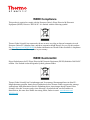


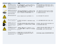

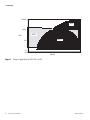

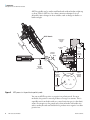

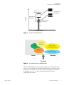
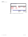


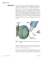
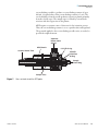

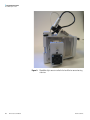
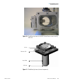


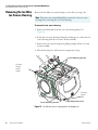

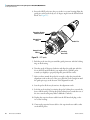


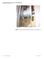

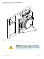


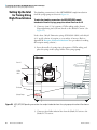
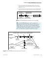


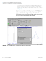


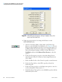


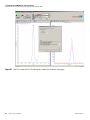


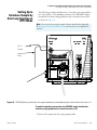


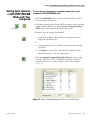


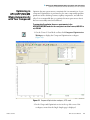


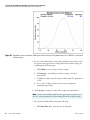


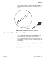

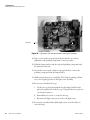


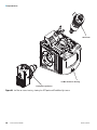
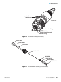

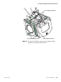
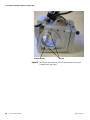
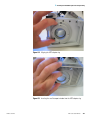
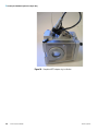


![TSQ Series Getting Started Guide Version C [FR]](http://vs1.manualzilla.com/store/data/006357565_1-ae930521dae4517a45cdbc191dde2ba3-150x150.png)