1
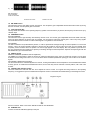
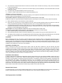
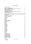
HR-2800
28 MHZ AM-FM
AMATEUR RADIO HF TRANSCEIVER
OWNER'S MANUAL
NOTICE !
It is recommended to carefully read this owner’s manual before using the product. This will also help to prevent illegal use of the
radio in violation of the regulations valid in the country where the product is used, as well as to avoid causing possible interferences
to other services.
Index
Introduction - Content of the packaging
Controls and operation
CTCSS function
Installation
Specifications - User Information
ESP Compander Diagram - CTCSS Diagram
PCB - Main Board & CPU Board
Diagram
Block Diagram
1
1
2-9
10
11
14
II
III - IV
V - VI
VII-VIII
NOTICE !
This transceiver has been factory programmed, in order to use the product immediately after purchase. The programming includes
the activation of frequencies in the HF 10 Meter Amateur Band, according to the technical rules in force for the use of this bands.
The manufacturer is not responsible for any modification to the harware or software of the product, which may possibly cause the
radio
Congratulations !
Congratulations for selecting and purchasing a K-PO quality product. K-PO HR-2800 is a 10-Meter band Amateur Radio transceiver
using advanced hardware and software design. This transceiver includes a number of advanced functions and systems, therefore it
is definitely necessary to carefully read this owner’s manual before using the radio. With a correct use of the product in accordance
with the operating method described in this manual, the product will offer a trouble free use for many years. K-PO is constantly
engaged to develop and provide quality products meeting the customers requirements, however any suggestion or comments on this
product that might help us to improve quality are warmly welcome.
Content of the packaging
Please check that all the following items are contained in the packaging :
•
•
•
•
•
•
•
Main unit (transceiver)
DC power cord with fuse holder and fuse
Dynamic microphone
Car mounting bracket
Car mounting bracket accessories (hardware, knobs, etc.)
Microphone bracket
Owner’s manual
Front panel
1. ANL-OFF Selector
This selector enables the ANL function (Automatic Noise Limiter). The ANL reduces electric and electromagnetic noise on the
operating frequency. Move the selector to ANL to enable the Automatic Noise Limiter and move it to OFF to disable it.
2. LOC-DX Selector
This selector enables the LOC function (Local), in order to attenuate the strength of the incoming signals. The attenuator is useful in
case of very strong incoming signals from local stations that, due to the high signal level, might cause distortion and poor quality of
the received signals. Move the selector to the DX (Long Distance) when receiving weak signals or from long distance. Move the
selector to LOC (Local) when receiving strong signals from local stations.
3. LCD Display
Large size (visible area mm 54 x 21) LCD display with orange colour backlighting system, for best readability. The LCD display
shows all the enabled functions as well as several other information and user programmable functions, like the full 5-digit frequency
readout. LCD also includes a digital 10-bar S/RF Meter to monitor the strength/power of the received and transmitted signals.
LCD Display
A. AM Icon
The AM icon is lighted when radio receives and transmits in AM mode (amplitude modulation).
B. FM Icon
The FM icon is lighted when radio receives and transmits in FM mode (frequency modulation).
C. SCAN Icon
The SCAN icon is lighted when the SCAN function (automatic search of busy frequencies) is enabled.
D. TRUCK Icon
The TRUCK icon is lighted when the special programmable TRUCK memory channel (for truck drivers) has been selected.
E. EMG Icon
The EMG icon is lighted when one of the special quick access frequencies has been selected.
F. ESP C E Icon
The ESP C E icon is lighted when one of the ESP (Electronic Speech Processor) functions has been enabled. The ESP is an RX &
TX electronic modulation processor.
G. RX Icon
The RX icon is lighted when radio is in receive mode.
H. TX Icon
The TX icon is lighted when radio is in transmit mode.
I.
DW Icon
The DW icon is lighted when the DUAL WATCH function (automatic monitoring of two frequencies) is enabled.
L. S/RF Digital Meter
A digital 10-bar S/RF METER indicates the strength of the received signal (from S0 to S9+30) in the receive mode and the
transmitter RF output power (0 to 20W) in the transmit mode.
M. Alphanumeric Digit
This alphanumeric digit indicates the fifth and last figure (in KHz) of the operating frequency.
N. LOW Icon
The LOW icon is lighted when the transmitter is in the LOW POWER (1W) mode.
O. LOCK Icon
The LOCK icon is lighted when the LOCK function is enabled.
P. M1-M4 Icons
The M1-M4 icon is lighted when one of the four user programmable memory channels has been selected.
Q. Alphanumeric Digit
These four numeric or alphanumeric digits indicate :
the first four figures of the operating frequency (in KHz).
the selected CTCSS code number
R. F Icon
The F icon is lighted when the F (Function) mode is enabled, which allows the use of the dual function keys (keys 6, 7, 8, 9, 10, 14).
4. ESP Indicator
This LED indicator lights up in red colour when the ESP (Electronic Speech Processor) function is enabled. The ESP is an RX & TX
electronic modulation processor.
5. TX/RX Indicator
This green-red dual colour LED indicator lights up in green colour when radio is in receive mode and in red colour when radio is in
transmit mode.
6. AM/FM and M1 Key
This key selects the AM or FM operating mode in both RX and TX modes. This key is also used to program and select the memory
channel M1 (refer to item .11).
7. SCAN and M2 Key
By pressing the SCAN key, the SCAN (automatic scanning of busy frequencies) function is enabled. To enable the SCAN function,
first turn the SQUELCH control (19) clockwise, until the background noise is cut. Then press the SCAN key, radio will automatically
start scanning all frequencies continuously and the SCAN icon (C) will appear on the LCD. Auto-scan stops if a signal is detected, in
order to let the user listen to the incoming signal, auto-scan will start again when no signal is detected on that frequency. If the PTT
Key (27) is pressed within 5 seconds, radio will remain on that frequency, otherwise scanning will start again. Auto-scan may be also
re-started at any time by pressing again the SCAN key. To exit the SCAN mode, shortly press the PTT button (27). This key is also
used to program and select the memory frequency M2 (refer to item .11).
8. LCR and M3 Key
By pressing the LCR (Last Channel Recall) key, radio will automatically select the last used frequency. This key is also used to
program and select the memory frequency M3 (refer to item .11).
9. DW and M4 Key
The DW (Dual Watch) function allows automatic alternate monitoring of two programmable frequencies. Set the first frequency to be
frequency to be monitored using the CHANNEL selector (13) or the frequency selection keys on the microphone (28, 30). To enable
the DW function, press the DW key for about 2 seconds, until the DW icon (I) appears and blinks on the LCD display. Now set the
second frequency to monitor using the CHANNEL selector (13) or the frequency selection keys on the microphone (28, 30). Press
again the DW key for about 2 seconds. The DW function is now enabled and the LCD display will alternately show the two
programmed frequencies. The DW icon (I) will be lighted on the LCD display. Monitoring stops if a signal is detected on one of the
two frequencies, in order to let the user listen to the incoming signal and will start again when no signal is detected on that frequency.
It is possible to transmit on that channel, by simply pressing the PTT key (27). If there is no transmission within 5 seconds,
monitoring will re-start. To exit the DW mode, shortly press the PTT button (27). This key is also used to program and select the
memory frequency M4 (refer to item .11).
10. TRUCK / ROGER BEEP Key
The TRUCK key is an exclusive memory function. This key allows quick access to a special programmed memory channel (i.e. an
emergency frequency, a favorite frequency, etc.). To program the TRUCK memory frequency, set the desired frequency using the
CHANNEL selector (13) or the frequency selection keys on the microphone (28, 30). Then press and hold the TRUCK key until the
TRUCK icon (D) appears on the LCD display. The TRUCK frequency is now stored in the special TRUCK memory and it can be
immediately re-called by simply pressing the TRUCK key (10). This key is also used to enable the Roger Beep function (refer to item
.11).
11. F (Function) Key
The F (Function) key is used to enable various functions.
MEMORY FREQUENCIES (M1-M4) PROGRAMMING
Set the frequency to be programmed and stored in one of the four available memories (M1-M4), using the CHANNEL selector (13) or
the frequency selection keys on the microphone (28, 30). Shortly press the F key and the F icon (C) will blink on the LCD display.
Now press and hold one of the memory keys M1, M2, M3 or M4 for about 2 seconds, until the memory frequency number will appear
on the LCD display (i.e. M1). All the specifications associated to each frequency will be stored in memory (i.e. AM/FM mode, EU/UK
mode, transmitter power, CTCSStone, etc.).
MEMORY FREQUENCIES (M1-M4) SELECTION
Shortly press the F key and the F icon (R) will blink on the LCD display. Now press one of the dual function keys (M1 to M4) to
quickly recall and access to one of the programmed memory frequencies. The selected memory frequency number will appear on
the LCD display (P).
CTCSS TONE SELECTION
Please see the CTCSS section at page. 10.
ROGERBEEP FUNCTION
To enable or disable the RB (Roger Beep Tone), shortly press the F key (11) and the F icon ® on the LCD will blink. Now press the
TRUCK key (10). The Rb.on icon (RB enabled) or the Rb.oFF icon (RB disabled) will be showed on the LCD.
12. Q.DN (Quick Down) Key
This key allows fast selection of the operating frequency downward. Each time this key is pressed, the frequency number moves
down by 100 KHz steps.
13. CHANNEL (FREQUENCY) Selector
This knob selects the desired frequency, in 5 KHz steps (frequency increments). The knob may be turned clockwise to upward
frequency selection or counter clockwise to downward frequency selection.
14. EMG Key
EMG
Press to quick access to one of the two pre-programmed special frequencies (28.500 MHz or 29.000 MHz). Each time this key is
pressed, radio will select the frequency of 28.500 MHz, then 29.000 MHz, then again the normal operating frequency. When one of
the special frequency is selected, the EMG icon (E) will appear on the LCD display.
CTCSS FUNCTION
To access the CTCSS (sub-audible tone coding) function (see the CTCSS section at page 10), shortly press the F key (11) and then
the EMG key (14).
15. ESP (Electronic Speech Processor) Key
The ESP (Electronic Speech Processor) is a unique feature available in some INTEK two-way radios. ESP means Electronic Speech
Processor, in other words electronic modulation processor. This audio processor is microprocessor controlled and it is also called
COMPANDER (Compressor-Expander). It works as a modulation compressor in transmit mode and as a modulation expander in
receive mode. The ESP allows to obtain a stronger, clear and clean audio signal and it is a great help in noisy areas and in case of
weak signals or in long distance communication. The efficiency of ESP is even greater when both stations use this device. The 2nd
generation ESP allows to enable only the TX compressor, only the RX expander or both systems.
To enable or disable the ESP functions, press the ESP key (4), as follows :
1) Press the key once to enable the TX modulation compressor. The ESP C (F) icon will appear on the LCD.
2) Press the key again to enable the RX modulation expander. The ESP E (F) icon will appear on the LCD.
3) Press the key again to enable both the TX modulation compressor and the RX modulation expander.
The ESP C E (F) icon will appear on the LCD.
4)
Press the key once again to disable all systems.
ESP performance
of the modulation
in RX and TX modes
Modulation without ESP
Modulation with ESP
16. MIC GAIN Control
This transceiver uses a high quality dynamic microphone. The microphone gain is adjustable with the MIC GAIN control. By turning
the knob clockwise, the microphone gain is increased.
17. Q.UP (Quick UP) Key
This key allows fast selection of the operating frequency upward. Each time this key is pressed, the frequency number moves up by
100 KHz steps.
18. PA/RFGAIN Control
RF GAIN CONTROL
This transceiver uses a high sensitivity and selectivity receiver circuit. The receiver gain is adjustable with the RF GAIN control. By
turning the knob clockwise, the receiver gain is increased. It is convenient to reduce the receiver gain in case of very strong signals
from local stations and to increase it in case of weak signals or long distance communications.
PA CONTROL
The radio includes the PA (Public Address) function, in order to spread audio messages through an external speaker. To use the PA
function, connect an external speaker (optional) to the PA jack (24) located on the rear side of the radio. Turn the PA/SQL knob
completely counter clockwise to the PA position. The PA icon (Q) appears on the LCD display. Now it is possible to press the PTT
key (27) and speak into the microphone to spread your message through the external speaker. Adjust the microphone gain with the
MIC GAIN knob (16) to the desired level.
19. AS/SQL Control
SQUELCH CONTROL (SQUELCH manual adjustment)
The SQUELCH control allows to silent the receiver by cutting the background noise, when no signals are received. Turn the knob
clockwise until the background noise is cut. Turn the knob counter clockwise (SQUELCH opening) in order to listen to the weakest
signals.
AS CONTROL (SQUELCH fixed setting)
The AS function allows to automatically silent the receiver, avoding the SQUELCH manual adjustment. A fixed SQUELCH threshold
is factory pre-set. To enable the fixed SQUELCH function, turn the knob fully counter clockwise to the AS position, until a click noise
is heard.
20. OFF/VOL (OFF /Volume) Control
This knob switches the radio ON and OFF and it adjusts the volume control. If no signals are being received on the operating
frequency, it is suggested to open the SQUELCH and adjust the volume to the desired level while listening to the background noise.
21. MICROPHONE Connector
Connect the supplied dynamic microphone to this connector, locking it through the ring nut.
Rear Panel
22. ANTENNA Connector
Antenna connector. Refer to the section INSTALLATION OF THE ANTENNA.
23. S-METER Jack
Connect an external S-METER (optional) to this jack.
24. PA Jack
If the PA function has to be used, connect to the external speaker (optional) to this jack. Refer to item no. 19.
25. EXT (External Speaker) Jack
This jack is for connecting an external speaker (optional).
26. 13.2VDC / 32VDC POWER CORD
13.2VDC / 32VDC input power cord.
Microphone
27. PTT (Push-to-Talk) Key
Transmitter key. Press the PTT key to transmit and release it to return to the receive mode.
28. UP (Frequency Selector) Key
Each time this key is pressed, the frequency moves 5 KHz upward.
29. LOCK (Keypad Lock) Key
The LOCK function is enabled when pressing this key, in order lock the keypad and prevent entering unwanted commands. When
the LOCK function is enabled, the LOCK icon (O) appears on the LCD display.
30. DOWN (Frequency Selector) Key
Each time this key is pressed, the frequency moves 5 KHz upward.
31. MICROPHONE Plug
Connect the 6-pole microphone plug with locking ring nut to the microphone connector (21) located on the front side of the radio.
Important !
Do never attempt to open the cabinet of the transceiver. No user serviceable parts inside. Internal modifications or tampering may
cause damage to the product, modify its technical specifications and will void warranty rights. If service or repair are required, please
refer to an authorised service centre or specialized technician.
CTCSS Function
50 CTCSS private codes are available. Different CTCSS tones may be associated to different frequencies, by storing it on the 4
memory frequencies (M1-M4) or on the special TRUCK memory frequency. Therefore up to 5 frequencies may be programmed and
stored (M1-M4 + TRUCK) with a CTCSS tone associated.
To set the CTCSS function, proceed as follows :
1) Set the desired frequency, using the CHANNEL selector (13) or the frequency selector keys on the microphone (28 and 30).
2)
3)
Press the F key (11) and the F icon (R) will blink on the LCD, then press the EMG key (14). The LCD (3) will show the current
frequency (Q) and the CTCSS tone number will blink (Q). The tone number 00 indicates that no CTCSS tone is programmed on
that frequency.
Select the desired CTCSS tone number, using the CHANNEL selector (13) or the frequency selector keys on the microphone
(28 and 30).
4)
5)
6)
7)
The CTCSS tone number selection does not need to be confirmed. After a CTCSS tone is stored, you may receive and transmit
on the current frequency.
In CTCSS mode, if the LCR key is pressed, the last used frequency will be recalled but it will be associated with the stored
CTCSS tone number.
In CTCSS mode, the DW (Dual Watch) function cannot be used.
To exit the CTCSS mode, press the F key (11) and then the EMG key (14).
FREQUENCY SCAN IN CTCSS MODE
In CTCSS mode, press the SCAN key (7) to start auto scanning of the frequencies associated to the current CTCSS tone. To stop
scanning, shortly press the SCAN key (7) or the PTT key (27).
PROGRAMMING MEMORY FREQUENCIES (M1-M4) WITH AN ASSOCIATED CTCSS TONE
A different CTCSS tone may be associated to a different frequency, by storing it in one of the four memory frequencies (M1-M4).
1)
2)
3)
Set the desired frequency and CTCSS tone, as above indicated.
Press the F key (11) and the F icon (R) will blink on the LCD. Press and keep pressed for about 2 seconds one of the four
memory frequencies keys (M1-M4). The programmed memory icon (i.e. M1) (P) will be showed on the LCD.
To recall the desired memory frequency, press the F key (11) (the F icon (R) will blink on the LCD) and then one of the memory
frequencies keys (M1-M4). The selected frequency (Q), the associated CTCSS tone number (Q) and the recalled memory
frequency (i.e. M1) (P) will appear on the LCD (3).
PROGRAMMING THE TRUCK MEMORY FREQUENCY WITH AN ASSOCIATED CTCSS TONE
To program the special TRUCK memory frequency, associated with a CTCSS tone, proceed as follows :
1) Set the desired frequency and CTCSS tone, as above indicated.
2) Press and keep pressed for about 2 seconds the TRUCK key (10). The TRUCK icon (D) icon will be showed on the LCD.
3)
The TRUCK memory frequency now is programmed and may be selected by simply pressing the TRUCK key (D). The selected
frequency (Q), the associated CTCSS tone number (Q) and the TRUCK icon (D) will appear on the LCD (3).
Installation
Before installing the main unit in the vehicle, check and select the most convenient location, in order that the radio will be easy to
reach and comfortable to operate, without disturbing or interfering with the vehicle drive. Use the supplied bracket and hardware to
install the radio. The bracket screws must be well tightened in order not to become loosen with the vehicle vibrations. The car
mounting bracket can be installed over or below the radio and the radio may be inclined as desired according to the specific type of
installation (under dashboard or track cabin roof installation).
Installation of the Main Unit
Before connecting the radio to the vehicle electric system, make sure that radio is switched off, with the OFF/VOL (20) knob
completely turned counter clockwise at OFF position. The DC power cable (26) of the radio is complete with a fuse holder with fuse
located on the red positive (+) wire. Connect the DC power cable to the vehicle electric system, with special attention to respect
correct polarity, even if the radio is protected against polarity inversion. Connect the red wire to the positive (+) pole and the black
wire to the negative (-) pole of the vehicle electric system. Make sure that the wires and terminals are firmly and stably connected, in
order to prevent cables from disconnecting or causing short circuits.
Installation of the Antenna
A specific mobile antenna designed for 28-30 MHz frequency range must be used. The antenna installation must be done by a
specialised technician or service centre. Please pay special attention to carefully install the antenna on the vehicle with perfect
connection to ground. Before connecting the antenna to the radio, it is necessary to check the correct operation of the antenna with
low standing wave ratio (S.W.R.), using adequate instruments. If not, the transmitter circuit of the radio could be damaged. The
antenna must be usually installed on the highest part of the vehicle, free from obstacles and as far away as possible from any source
of electric or electromagnetic noise. The RF antenna coaxial cable must not be damaged or pressed on its way between antenna
and the radio. The correct operation of the antenna and the low standing wave ratio (S.W.R.) must be checked periodically. Connect
the RF antenna coaxial cable to the antenna connector (22), located on the rear side of the radio.
Amateur Radio License
To operate this radio, you must have an Amateur Radio License. It is the user’s responsibility to have the necessary authorization or
license to operate this radio in accordance with the regulations of the country where the radio has to be used.
Checking Operation of the Radio
Once radio has been connected to the vehicle electric system and to the antenna, the correct operation of the system may be
checked. Please proceed as follows :
1) Check that the power cable is correctly connected.
2) Check that the RF antenna coaxial cable is correctly connected.
3) Connect the microphone to the connector (21), located on the front side of the radio.
4) Rotate the AS/SQL (19) knob counter clockwise.
5) Turn radio on using the OFF/VOL (20) knob and adjust volume to the desired level.
6) Set the desired frequency, using the CHANNEL selector (13) or the frequency selector keys on the microphone (28 and 30).
7) Rotate the AS/SQL (19) knob clockwise, to cut the background noise.
8) Press the PTT (27) key to transmit and release it to receive.
9) Check the level of the received and transmitted signals on the digital bar S/RF Meter (L) on the LCD display.
The transceiver will work correctly.
Specifications
General
Frequency range
Operating modes
Frequency control
Operating temperature
DC input voltage
Size
Weight
28.000-29.700 MHz HF 10 Meter Band
FM-AM
P.L.L.
-10°/+55°C
12.0VDC(minimum) to 32.0VDC(maximum)
153 (L) x 50 (H) x 210 (D) mm
1.5 kg
Receiver
System
IF
Sensitivity
Audio output
Audio distorsion
Image rejection
Adjacent channel
Signal/noise ratio
Current drain
Double conversion, CPU controlled super-eterodine
1° 10.695 MHz / 2° 455 KHz
0.5uV for 20dB SINAD (FM)
0.5uV for 20dB SINAD (AM)
@10% THD 2.5W at 8 ohm
<8% at 1 KHz
65dB
65dB
45dB
250mA (stand-by)
Transmitter
System
Maximum RF power
Modulation
Impedance
Current drain
CPU controlled P.L.L. systhesizer
20W
85% to 90% (AM)
1.8 KHz ±0.2 KHz (FM)
50 ohm unbalanced
6.0A (at no modulation)
User Information
in accordance with art. 13 of the Legislative Decree of 25th July 2005, no. 15 ”Implementation of Directives 2002/95/EC, 2002/96/EC
and 2003/108/EC, relative to reduction of the use of hazardous substances in electrical and electronic equipment, in addition to
waste disposal”.
The crossed bin symbol shown on the equipment indicates that at the end of its working life the product must be collected
separately from other waste.
The user must therefore take the above equipment to the appropriate differentiated collection centres for electronic and
electro technical waste, or return it to the dealer when purchasing a new appliance of equivalent type, in a ratio of one to
one.
Appropriate differentiated waste collection for subsequent recycling, treatment and environment-friendly disposal of the discarded
equipment helps to prevent possible negative environmental and health effects and encourages recycling of the component
materials of the equipment.
Illegal disposal of the product by the user will be punished by application of the administrative fines provided for by the legislative
decree no. 22/1997 (article 50 and following of the legislative decree no. 22/1997).