1
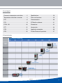
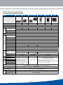
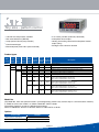
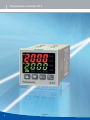
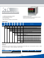
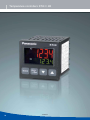
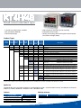
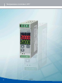
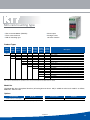
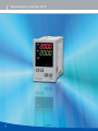
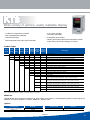
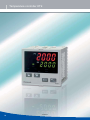
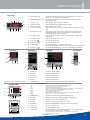
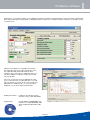
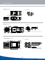
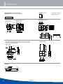
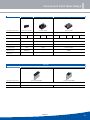
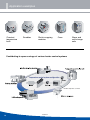
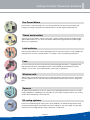
OVERVIEW
TEMPERATURE CONTROLLERS
15/06/2012
Panasonic temperature controllers
s Ecological
s Reliable
s Highest quality
s Cost-saving
2
15/06/2012
Content
Panasonic temperature controllers. . . . . .2
Specifications . . . . . . . . . . . . . . . . . . . . .18
Temperature controllers overview. . . . . . .4
Parts and functions. . . . . . . . . . . . . . . . .19
KT2 . . . . . . . . . . . . . . . . . . . . . . . . . . . . . .6
Communication. . . . . . . . . . . . . . . . . . . .20
KT4 . . . . . . . . . . . . . . . . . . . . . . . . . . . . . .8
KT-Monitor software . . . . . . . . . . . . . . . .21
KT4H / 4B . . . . . . . . . . . . . . . . . . . . . . . .10
Dimensions. . . . . . . . . . . . . . . . . . . . . . .22
KT7 . . . . . . . . . . . . . . . . . . . . . . . . . . . . .12
Accessories . . . . . . . . . . . . . . . . . . . . . .24
KT8 . . . . . . . . . . . . . . . . . . . . . . . . . . . . .14
Application examples . . . . . . . . . . . . . . .26
KT9 . . . . . . . . . . . . . . . . . . . . . . . . . . . . .16
Further Panasonic products . . . . . . . . . .27
Overview
Display character height (mm)
PV:
SV:
8.7
8.7
12
6
10.2
8.8
7.4
7.4
11.2
11.2
18.2
13.2
Dimensions
WxHxD
(mm)
KT9
Big display
96 x 96 x 98.5
KT8
Easy readable
display
48 x 96 x 98.5
KT7
Din rail
22.5 x 75 x 100
KT4
high performance
48 x 48 x 95
KT4H/KT4B
11 segment LCD display
48 x 48 x 62
KT2
48 x 24 x 98.5
Nine step
pattern
control
15/06/2012
3
Temperature controllers overview
Common features
s Multi-input: Versatile thermocouple, RTD, DC current, DC voltage
s Control modes: PID, on/off control, Anti-Reset-Windup (ARW)
s Control output: Relay, non-contact voltage output
(for SSR drive, DC output)
s Accuracy: ± 0.2% span
s Simple operation
s Heater-burn-out alarm available
s Alarm output with 9 different operation modes
s RS485 ASCII/Modbus communication available
s Supply voltage: 24VAC/DC or 100 to 240VAC
s Compliant with UL, CSA standards and CE marking
Output types
4
Output method
Characteristics
Relay contact output
Relay contact output is used for switching up to 3A 250 VAC (resistive load) in applications in which the on-off frequency is low.
Voltage output for SSR drive
This voltage output is used for driving the SSR. Since the SSR
is a semiconductor relay, contact life is long. This type is used
in applications in which the on-off frequency is high. Up to 40mA
12VDC can be switched.
DC current output
This current output is used to control a power regulator. Smooth
and accurate control is possible because phase control corresponds to the current output.
15/06/2012
Selection of products
Model
Dimensions (W x H x D)
KT2
KT4
KT4H / KT4B
KT7
KT8
KT9
48 x 24 x 98.5mm
48 x 48 x 95mm
48 x 48 x 62mm
22.5 x 75 x 100mm
48 x 96 x 98.5mm
96 x 96 x 98.5mm
Protection
IP66 (applicable only to the front panel subject to rubber gasket employed) except for KT7
Output type
Output range
1a
1a
1a1b
1a
1a1b
1a1b
Control
output
Relay contact
3A 250VAC (resistive load), 1A 250VAC (inductive load cosØ=0.4), electric life: 100,000 times
DC voltage
12 - 14VDC; max. load current: 40mA (short-circuit protected)
DC current
4 to 20mA DC load resistance: Max. 550W
Input type
Input range
–200 to 1370°C
K
Thermocouple
–199.9 to 400°C
J
–200 to 1000°C
R
0 to 1760°C
S
0 to 1760°C
B
0 to 1820°C
E
T
–200 to 800°C
–199.9 to 400°C
–200 to 400°C
N
–200 to 1300°C
PL-II
–200 to 1390°C
C (W/Re5-26)
0 to 2315°C
–200 to 850°C
RTD
Pt100
–199.9 to 850°C
DC
current
4 to 20mA DC
0 to 20mA DC
0 to 1VDC
DC
voltage
–200 to 850°C
JPt100
3-conductor system
0 to 10VDC
1 to 5VDC
0 to 5VDC
Control mode
Communication function
EMC directives
Low-voltage directives
–199.9 to 850°C
–200 to 500°C
–199.9 to 500°C
–200 to 500°C
–199.9 to 500°C
–1999 to 9999, –199.9 to 999.9
–19.99 to 99.99, –1.999 to 9.999
s3CALINGANDCHANGETOTHEDECIMAL
point position is possible for DC
current and DC voltage input.
s$#CURRENTINPUTISSUPPORTEDWITH
an externally mounted 50Ω shunt
resistor (sold separately).
–1999 to 9999, –199.9 to 999.9
–19.99 to 99.99, –1.999 to 9.999
–2000 to 10,000
s3CALINGANDCHANGETOTHEDECIMALPOINTPOSITIONISPOSSIBLE
for DC current and DC voltage input.
s$#CURRENTINPUTISSUPPORTEDWITHANEXTERNALLYMOUNTED
50Ω shunt resistor (sold separately).
Actions mentioned below can be selected by key operation. [Default PID] PID (with auto-tuning function),
PI, PD (with manual reset function), P (with manual reset function), ON/OFF action
100 to 240VAC
24VAC/DC
Supply voltage (must be specified)
Standards
–199.9 to 400°C
RS485/MODBUS Protocol (MODBUS is a communication protocol developed for PLCs by Modicon Inc.)
communication speed: 2400/4800/9600/19200bps
EN61000-6-4/EN61000-6-2
EN61010-1/IEC61010-1
Further specifications see page 19.
15/06/2012
5
Temperature controller KT2
6
15/06/2012
Tiny size - pattern control
s 2 set values possible (externally selectable)
s 2nd optional alarm output
s 1/32 DIN size temperature controller
s Size 48 x 24 x 95.5mm (WxHxD)
s 9-step pattern control (ramp function)
s Heating and cooling control with 2nd optional control
output (relay)
s Analogue value converter function
s Panel-mounted type
s IP66 waterproof (front side if panel mounted)
Product types
Base Power Sensor Control Alarm
model supply input output output
Heating/ Heater Commucooling burnout nication
control
alarm
function
AKT2
Description
48 x 24 x 98.5mm
1
100 to 240VAC
2
24VAC/DC
1
Multi-input (thermocouple, RTD, DC current and DC voltage)
1
Relay contact output 1a 3A 250VAC
2
Non-contact voltage output (for SSR drive)
3
Current output
2
0
0
Blank
When neither the heating/cooling nor the communication function is added:
Relay contact output (alarm 1): Can be used
Open collector output (alarm 2): Can be used
1
1
0
Blank
When only the heating/cooling function is added:
Relay contact output (alarm 1): Cannot be used
Open collector output (alarm 2): Can be used
1
0
0
1
When only the communication function is added:
Relay contact output (alarm 1): Can be used
Open collector output (alarm 2): Cannot be used
0
1
0
1
When both the heating/cooling and the communication functions are added:
Relay contact output (alarm 1): Cannot be used
Open collector output (alarm 2): Cannot be used
Note: When heating/cooling is selected, alarm output 1 cannot be used. When the communication function is selected, alarm output 2 cannot be used.
Model No.
(Ex) Model No. when the optional functions (of heating/cooling control: relay contact output + communications function)
is added on to the basic model is as follows; Model No.: AKT21110101
The optional functions are only the following four patterns:
AKT2□1□200 Blank; AKT2□1□110 Blank; AKT2□1□1001; AKT2□1□0101
Options
Product name
Model No.
Shunt resistor (for current input)
AKT4810
Terminal cover
AKT2801
Note: When a current input is specified, a shunt resistor (sold separately) is required.
15/06/2012
7
Temperature controller KT4
8
15/06/2012
Small-sized standard type
s 2nd optional alarm output
s Heating and cooling control with 2nd optional control
output (non-contact voltage output)
s 1/16 DIN size temperature controller
s Size 48 x 48 x 95mm (WxHxD)
s Panel-mounted type
s IP66 waterproof (frontside if panel mounted)
Product types
Base
model
Heating/ Heater CommuPower Sensor Control Alarm
cooling burnout nication
supply input
output output
control
alarm
function
AKT4
Description
48 x 48 x 95mm
1
100 to 240VAC
2
24VAC/DC
1
Multi-input (thermocouple, RTD, DC current and DC voltage)
1
Relay contact output 1a 3A 250VAC
2
Non-contact voltage output (for SSR drive)
3
Current output
1
Relay contact output 1a (alarm output 1)
2
Relay contact output 1a (alarm output 2)
0
Not available
4
SSR output 0.3A 250VAC (heating/cooling control not supported when alarm
output 2 is selected)
0
Not available
1
5A (heater burn-out alarm not supported when control output is current
output type/not supported when heating and cooling control is selected)
2
10A (heater burn-out alarm not supported when control output is current
output type/not supported when heating and cooling control is selected)
3
20A (heater burn-out alarm not supported when control output is current
output type/not supported when heating and cooling control is selected)
4
50A (heater burn-out alarm not supported when control output is current
output type/not supported when heating and cooling control is selected)
Not available
1
Available
1.) CT1 or CT2 for current detection is provided as an accessory when heater burn-out alarm function is added.
2.) Event output wil be shared if you choose alarm output 2 and the heater burn-out alarm.
Model No.
(Ex) Model No. when the optional functions (of heating/cooling control: SSR output + communications function) is added
on to the basic model is as follows; Model No.: AKT41111401
Options
Product name
Model No.
Product name
Description
Model No.
Shunt resistor (for current input)
AKT4810
Installation frame
For KT4, KT4H and KT4B
AKW4822
Terminal cover
AKT4801
Note: When a current input is specified, a shunt resistor (sold separately) is required.
15/06/2012
9
Temperature controllers KT4H / 4B
10
15/06/2012
Small-sized standard type
s IP66 waterproof (frontside if panel mounted)
s 2nd optional alarm output
s 1/16 DIN size temperature controller
s Size 48 x 48 x 62 (WxHxD)
s Panel-mounted type
s Heating and cooling control with optional control output
(non-contact voltage output)
Product Types
Base
model
Power Sensor Control Alarm
supply input
output output
Heating/ Heater Commucooling burnout nication
control
alarm
function
AKT4H/-B
Description
48 x 48 x 62mm
1
100 to 240VAC
2
24VAC/DC
1
Multi-input (Thermocouple, RTD, DC current and DC voltage)
1
Relay contact output 1a 3A 250VAC
2
Non-contact voltage (for SSR drive)
3
0
DC current
1
2
Heater burn-out alarm not possible
1 point (1a)
0
2 points (1a + 1a)
0
Not available
Heating/cooling control output not possible
1
0
Relay contact
Heater burn-out alarm not possible
2
0
Non-contact voltage (for
SSR drive)
Heater burn-out alarm not possible
0
Not available
1 or 2
0
3
Single phase 20A (heater burn-out alarm not supported when control output is
DC output type/not supported when heating and cooling control is selected)
1 or 2
0
4
Single phase 50A (heater burn-out alarm not supported when control output is
DC output type/not supported when heating and cooling control is selected)
1 or 2
0
5
Three phase 20A (heater burn-out alarm not supported when control output is
DC output type/not supported when heating and cooling control is selected)
1 or 2
0
6
Three phase 50A (heater burn-out alarm not supported when control output is
DC output type/not supported when heating and cooling control is selected)
Blank
Not available
1
Serial communication RS485
2
Contact input
1.) CT1 or CT2 for current transformer is provided as an accessory when heater burn-out alarm function is added.
2.) Under some conditions, option functions (shaded items) may not be available; please check the description in the table above for details.
Model No.
(Ex) Model No. when the optional functions (heating/cooling control + communication function) are added on to the basic
model is as follows; Model No.: AKT4H1111101 / AKT4B111100
Options
Setting software
Product name
Model No.
Product name
Description
Shunt resistor (for current input)
AKT4810
KT monitor
Editing of all types of data, file saving, monitoring of readings, Saving of log files
Terminal cover
AKT4H801
Tool cable
AKT4H820
Installation frame for KT4, KT4H/-B
AKW4822
Note: Please download user manual from our website.
15/06/2012
11
Temperature controllers KT7
12
15/06/2012
Slim rail-mounting type
s Alarm output
s Analogue value
converter function
s Size 22.5 x 75 x 100mm (WxHxD)
s Front screw terminals
s DIN rail mounting type
Product Types
Base
model
Power
supply
Sensor
input
Control
output
Alarm
output
Heating/
cooling
control
Heater
burnout
alarm
Communication
function
AKT7
Description
22.5 x 75 x 100mm
1
100 to 240VAC
2
24VAC/DC
1
Multi-input (thermocouple, RTD, DC current and DC voltage)
1
Relay contact output 1a 3A 250VAC
2
Non-contact voltage output (for SSR drive)
3
Current output
1
Open collector output (alarm output 1)
0
Not available (without heating/cooling function)
0
Not available
1
5A (not available for current output type) open collector output
2
10A (not available for current output type) open collector output
3
20A (not available for current output type) open collector output
4
50A (not available for current output type) open collector output
Not available
1
Available
CT1 or CT2 for current detection is provided as an accessory when heater burn-out alarm function is added.
Model No.
(Ex) Model No. when the optional functions (of heating burn-out alarm: 10A) is added on to the basic model is as follows;
Model No.: AKT7111102
Options
Product name
Model No.
Product name
Model No.
Shunt resistor (for current input)
AKT4811
Mounting rail
ATA48011
Note: When a current input is specified, a shunt resistor (sold separately) is required.
15/06/2012
13
Temperature controller KT8
14
15/06/2012
Wide variety of options, easily readable display
s 2 set values possible
(externally selectable)
s 2nd optional alarm output
s 1/8 DIN size temperature controller
s Size 48 x 96 x 98.5mm (WxHxD)
s Panel-mounted type
s IP66 waterproof (front side if panel mounted)
s Heating and cooling control with 2nd optional control
output (relay, non-contact voltage, or current)
Product Types
Heating/ Heater CommuBase Power Sensor Control Alarm
cooling burnout nication
model supply input output output
control
alarm
function
AKT8
Description
48 x 96 x 98.5mm
1
100 to 240VAC
2
24VAC/DC
1
Multi-input (thermocouple, RTD, DC current and DC voltage)
1
Relay contact output 1a 1b 3A 250VAC
2
Non-contact voltage output (for SSR drive)
3
Current output
1
Relay contact output 1a (alarm output 1)
2
Relay contact output 1a (alarm output 2)
0
Not available
1
Relay contact output 1a
2
Non-contact voltage output (for SSR drive)
3
Current output
0
Not available
1
5A (heater burn-out alarm not supported when control output is current output
type/not supported when heating and cooling control is selected)
2
10A (heater burn-out alarm not supported when control output is current output type/not supported when heating and cooling control is selected)
3
20A (heater burn-out alarm not supported when control output is current output type/not supported when heating and cooling control is selected)
4
50A (heater burn-out alarm not supported when control output is current output type/not supported when heating and cooling control is selected)
Not available
1
Available
1) CT1 or CT2 for current detection is provided as an accessory when heater burn-out alarm function is added.
2) If a communication function is added, second main setup is not possible.
Model No.
(Ex) Model No. when the optional functions (of alarm output; alarm output 2 + heating/cooling control: current output) are
added on to the basic model is as follows; Model No.: AKT8111230
Options
Product name
Model No.
Product name
Model No.
Shunt resistor (for current input)
AKT4810
Mounting frame
AKW8822
Terminal cover
AKT8801
Note: When a current input is specified, a shunt resistor (sold separately) is required.
15/06/2012
15
Temperature controller KT9
16
15/06/2012
Big and easily readable display
s 1/4 DIN size temperature controller
s Size 96 x 96 x 98.5mm (WxHxD)
s 2 set values possible (externally selectable)
s 2nd optional alarm output
s Panel-mounted type
s IP66 waterproof (front side if panel mounted)
s Heating and cooling control with 2nd optional control
output (relay, non-contact voltage, or current)
Product Types
Heating/ Heater CommuBase Power Sensor Control Alarm
cooling burn out nication
model supply input output output
control
alarm
function
AKT9
Description
96 x 96 x 98.5mm
1
100 to 240VAC
2
24VAC/DC
1
Multi-input (thermocouple, RTD, DC current and DC voltage)
1
Relay contact output 1a 1b 3A 250VAC
2
Non-contact voltage output (for SSR drive)
3
Current output
1
Relay contact output 1a (alarm output 1)
2
Relay contact output 1a (alarm output 2)
0
Not available
1
Relay contact output 1a
2
Non-contact voltage output (for SSR drive)
3
Current output
0
Not available
1
5A (heater burn-out alarm not supported when control output is current output
type/not supported when heating and cooling control is selected)
2
10A (heater burn-out alarm not supported when control output is current
output type/not supported when heating and cooling control is selected)
3
20A (heater burn-out alarm not supported when control output is current
output type/not supported when heating and cooling control is selected)
4
50A (heater burn-out alarm not supported when control output is current
output type/not supported when heating and cooling control is selected)
Not available
1
Available
1.) CT1 or CT2 for current detection is provided as an accessory when heater burn-out alarm function is added.
2.) If a communication function is added, second main setup is not possible.
Model No.
(Ex) Model No. when the optional functions (of alarm output; alarm output 2 + heating/cooling control: non-contact voltage
output) are added on to the basic model is as follows; Model No.: AKT9111220
Options
Product name
Model No.
Shunt resistor (for current input)
AKT4810
Terminal cover
AKT9801
Note: When acurrent input is specified, a shunt resistor (sold separately) is required.
15/06/2012
17
Specifications
Model
KT2
Power consumption
KT4
KT4H / KT4B
Approx. 5VA
KT9
Approx. 8VA
Frequency
KT7
Approx. 6VA
50/60Hz
Alarm output 1 (EVT1)
Relay contact
Contact material: Ag alloy)
Relay contact
1a 3A 250VAC
(resistive load)
1a 1A 250VAC
(inductive load)
cosØ=0.4)
Relay contact 1a 3A 250VAC (resistive load)
Electric life: 100,000 times
Open collector,
control capacity:
24VDC 0.1A (max.)
Alarm output 2 (EVT2)
Open collector
0.1A 24VDC
The same as the one of Alarm output 1
None
Within ±0.2% ±1 digit of each input span or within ±2°C whichever is greater.
However, R and S input; within ±6°C in the range of 0 to 200°C
B input 0 to 300°C: Accuracy is not guaranteed.
K, J, T, E and N input less than 0°C: Within ±0.4% ±1 digit of input span
Thermocouple
Accuracy
RTD
Within ±0.1% of each input span ±1 digit or ±1°C whichever is greater
Within ±0.2% of each input span ±1 digit
DC current / DC voltage
Sampling period
250ms
Thermocouple & RTD: 0.1 to 100.0°C
DC current and DC voltage: 1 to 1000 (the decimal point place follows the selection)
Hysteresis (ON/OFF)
Proportional band
For sensor input
range and DC
current, DC voltage 0.0 to 110.0%
Thermocouple: 0 to 1000°C
RTD: 0.0 to 999.9°C / Decimal point input KT4H/KT4B: 0.0 to 1000°C
DC current and DC voltage: 0.0 to 100.0%
Integral time
0 to 1000 seconds
Derivative time
0 to 300 seconds
Proportional cycle
When 100 to 240VAC; 85 to 264VAC, when 24VAC/DC; 20 to 28VAC/DC
Insulated resistance
Breakdown voltage
For sensor input
range and DC
current, DC voltage
0.0 to 110.0%
1 to 120 seconds
Allowable voltage fluctuation
500VDC 10M1 or greater
1.5kVAC for 1min
between input terminal and power
terminal, output
terminal and
power terminal
1.5kVAC for 1min between input terminal and ground terminal, input terminal and
power terminal, power terminal and ground terminal, output terminal and ground
terminal, output terminal and power terminal
1.5kVAC for 1min
between input
terminal and power
terminal, output
terminal and power
terminal
Malfunction vibration
10 to 55Hz (0.35mm) in each
direction (120ms sweep) for 10min.
10 to 55Hz
(1 cycle/min.), single
amplitude 0.35mm
(10 min. on 3 axes)
10 to 55Hz (0.35mm) in each direction
(120ms sweep) for 10min.
Breakdown vibration
10 to 55Hz (0.75mm) in each
direction (120ms sweep) for 10min.
10 to 55Hz
(1 cycle/min.), single
amplitude 0.75mm
(1 hour on 3 axes)
10 to 55Hz (0.75mm) in each direction
(120ms sweep) for 10min.
Malfunction shock
X, Y & Z each direction for 5 times 98m/s2 (10G)
Breakdown shock
Same as above, but 294m/s2 (30G)
Ambient temperature
0 to 50°C
Ambient humidity
Mass
Display character height
Alarm output 2
Options
Heating/Cooling control
35 to 85% RH (no condensation)
Approx. 120g
Approx. 130g
Approx. 120g
Approx. 240g
Approx. 370g
Approx. 150g
PV: 8.7mm
SV: 8.7mm*
PV: 10.2mm
SV: 8.8mm
PV: 12mm
SV: 6mm
PV: 11.2mm
SV: 11.2mm
PV: 18mm
SV: 13.2mm
PV: 7.4mm
SV: 7.4mm
0.1A 24VDC
The same as the one of alarm output 1
Relay contact:
1a 3A 250VDC
(resistive load)
Heater burn-out alarm
Output
Tool port
Non-contact
relay
0.3A 250VAC
(resistive load)
s Relay contact 1a: 3A
250VAC (resistive load)
Electric life: 100,000 time
s Non contact voltage:
12VDC ±15% max. 40mA
(short circuit protected)
18
None
s Relay contact: 1a 250VAC 3A (resistive
load),
s DC current: 4 to 20mA DC Load resistance:
Max. 550 (short-circuit protected)
s Non-contact voltage: 12 – 14VDC max.
40mA Electric life: 100,000 times 250VAC 1A
(inductive load cosø=0.4),
None
Setting accuracy: Within 5% of heater rated current
None
Relay contact 1a 250VAC 3A (resistive load), Electric life: 100,000 times
None
Communication interface
C-MOS level, cannot be
used at the same time
as serial communication
(option). This port can only
be used with the tool cable
(AKT4H820).
*PV/SV switching display
18
KT8
15/06/2012
None
Open collector,
Control capacity:
24VDC 0.1A (Max.)
Parts and functions
KT2 Series
3
4
5
1
PV/SV display (red):
Indicates the input value and setting value. During setting mode, characters and
setting value of the setting item are indicated in turn.
2
MEMO/STEP display (green):
Indicates memory number during fixed value control. Indicates step number
during program control.
3
PV indicator (red):
Lights up when the input value (PV) is indicated.
8
4
SV indicator (green):
Lights up when the main setting value (SV) is indicated.
9
5
AT indicator (yellow):
Flashes during AT (auto-tuning).
6
T/R indicator (yellow):
Flashes during serial communication (lit while sending data, unlit while receiving
data).
7
OUT indicator (green):
Lights up when control output or OUT1 (heating side, option heating/cooling
control) is ON: For DC current output type, it flashes corresponding to the
manipulated variable in a 0.25 second cycle.
8
EV1 indicator (red):
Lights up when event output 1 or OUT2 (cooling side, option heating/cooling
control) is ON.
9
EV2 indicator (red):
Lights up when event output 2 is ON.
10
Increase key ( △ ):
Increases the numeric value.
11
Decrease key ( ▽ ):
Decreases the numeric value.
12
Mode key ( MODE ):
Selects the setting mode or registers the setting value.
(By pressing the Mode key, the setting value or selected value can be registered.)
13
OUT/OFF key ( OUTOFF ):
The control output OUT/OFF or program control RUN/STOP can be switched.
6
7
1
2
10 11 12 13
KT4 Series
KT9 Series
KT8 Series
1
KT7 Series
1
1
1
2
2
2
2
3
4
5
6
3
4
3
5
3
4
Note: Color selection is the same for each size.
1
2
2
SV display:
Indicates SV (setting value)
3
Increase key:
Increases numerical value
4
Decrease key:
Decreases numerical value
5
Mode key:
Switches the setting mode
6
OUT/OFF key:
Control output is turned on or off when control output is ON.
OUT2
EVT1
EVT2
LOCK
Lights respectively when temperature unit *F/*C is selected
Lights during serial communication (option) TX output.
Flashes during auto-tuning or auto-reset
Lights when control output is ON or Heating output (option) is ON. For DC current ouptut type, it
flashes corresponding to the manipulated variable in 0.25 second cycles
Lights when cooling output (option) is ON.
Lights when alarm 1 output is ON.
Lights when alarm 2 output (option) is ON or heater burn-out alarm (option) is ON.
Lights when lock 1, Lock 2 or lock 3 is selected.
2
MEMO display
Indicates the set value memory number (backlight: green).
3
PV display
Indicates the PV (process variable) (backlight: red/orange/green).
4
SV display
Indicates the SV (set value) (backlight: green).
5
Mode key
Selects the setting mode and registers the set value.
6
OUT/OFF key
The control output ON/OFF or auto/manual control can be switched.
7
Increase key
Increases the numeric value.
8
Decrease key
Decreases the numeric value.
9
Tool connector
By connecting the tool cable, the following operations can be conducted from the
external computer using the exclusive tool software.
7
5
6
8
(Bottom side)
Action indicators (backlight: orange)
*F*C
T/R
AT
OUT1
4
M
6
Indicates PV (process variable)
3
°C
5
PV display:
1
KT4H/4B Series
4
5 6
1
sReading and setting of SV, PID and various set values from external computer
sReading of PV and action status
sFunction change
15/06/2012
19
19
Communication/software
Communication KT series
Communication via RS485 and Modbus (ASCII) or Modbus RTU protocol
Example 1
Example 2
Multidrop communication with a programmable logical controller (PLC)
Multidrop communication with a personal computer
FP PLC
with FPG-COM3 communication cassette
PC with RS232 interface
Standard ASCII, Modbus ASCII or Modbus RTU protocol
Standard ASCII or Modbus ASCII protocol
SV1
AT
MODE
OUT
SV2
TX/RX
SV1
AT
MODE
SV2
OUT
TX/RX
MODE
Converter
RS232 – RS485
e.g. AFP8532J
OUT
OFF
OFF
OFF
KT4
KT4
RS485
SV1
SV2
TX/RX
SV1
AT
MODE
OUT
A1
EVT
EVT
EVT
AT
KT4
SV
A1
A1
EVT
EVT
EVT
TX/RX
SV2
OUT2
OUT2
SV
SV
A1
OUT1
OUT1
OUT1
OUT2
SV
A1
PV
PV
PV
OUT2
OUT2
SV
A1
SV1
OUT1
OUT1
OUT1
OUT2
SV
RS232
PV
PV
PV
SV2
TX/RX
SV1
AT
MODE
SV2
OUT
TX/RX
AT
MODE
OUT
OFF
OFF
OFF
KT4
KT4
KT4
RS485
Up to 31 units can be connected
Up to 31 units can be connected
With the optional communication function all settings can be entered or changed. Input value (PV) and other parameters can be
read easily. All commands are described in the KT instruction manual.
Communication via MEWTOCOL (slave) with any FP series PLC*
Item
Specification
Communication type
Half-duplex
Communication speed
Select 2400, 4800, 9600 or 19200 bps using key operation
Synchronization type
Asynchronous
Protocols
Standard protocol (ASCII), Modbus (ASCII) or Modbus RTU mode (8-bit binary coding), KT4H also MEWTOCOL (Slave)
Coding
ASCII/binary
Error correction
Command re-send
Error detection
Parity check, CRC-16 (RTU), LRC (ASCII)
Data structure
Start bits: 1
Data bit: 7 (ACII), 8 (RTU)
Parity: Even, No, Odd (Selectable), KT2: Even (ASCII), None (RTU)
Stop bit: 1/2
Interface
RS485 compliant
No. of nodes
31
Maximum cable length
1,000m (cable resistance must be within 501)
Note: Main setting no.2 is not possible on the KT8 and KT9 when the communication functions are added.
Communication and software KT4H / KT4B
Connect several KT4H to FP series PLCs
MEWTOCOL communications protocol is built in. Up to 31 units can be connected and data can be collected using a
FP-Sigma) PLC.
Comes with MEWTOCOL. Collect data with the PLC.
FP (Sigma)
Standard external tool port
Tool port of KT4H
With the external tool port, all settings can be loaded and made.
20
20
(Bottom
side)
All data settings and display
of temperature profile
USB
port
KT Monitor software
AKT4H820
Tool port converter cable
15/06/2012
KT-Monitor software
KT Monitor is a convenient software tool for editing the parameters of KT4H, saving parameters in a file, monitoring of temperature
data, and monitoring and saving log files of designated values. Parameters can easily be understood and are accessible in a clear,
convenient form.
With the Trace display you can display and analyze
the temperature PV, the set value SV and the control
the output MV. MV2 will be indicated only when
heating/cooling control option is added. All values can
also be recorded in a CSV-file for further processing
with e.g. Excel ®.
The colors of the traces are user-definable, the same
goes for the interval for recording data (min. 1 second).
The total number of records can be set in a range from
600 (10 min.) to 9,000 (15 min.). To scale the values
displayed, you can enter upper and lower limits.
Ordering information:
KT Monitor set CD with software,
manuals, tool port cable AKT4H820
Requirements:
PC with Windows 98/ME/2000 or XP,
USB port, tool cable AKT4H820, USB
driver installed (included with KT Monitor)
15/06/2012
21
21
Dimensions
KT2 series (unit: mm)
Panel cutout
47.6
45 +0.6
0
22.2 +0.3
0
44.8
40
Rubber packing
Mounting frame
60
36.5
MEMO/STEP
PV
SV
AT
T/R
OUT
EV1
21.5
24
EV2
OUT
MODE
OFF
KT2
48
10.6
48
98.5
KT4 series (unit: mm)
Panel cutout
Screw type mounting
Rubber gasket
75
45+0.5
0
PV
OUT1
75
OUT2
SV
EVT
SV1
SV2
TX/RX
59.7
AT
MODE
45 +0.5
0
44.5
A1
OUT
Lateral close mounting
n: Number of units mounted
45 +0.5
0
OFF
n x 48 – 3 +0.5
0
KT4
48
11.5
Note: The communications terminal is the screw terminal on the back of the
unit.
95
KT4H / KT4B series (unit: mm)
Panel cutout
1.5
Rubber gasket
Mounting frame
Terminal cover
(sold separately)
M3 screw
44.5
59.2
75
n x 48 – 3
+0.5
47.5
45
45
56.0
48.0
6
22
61.0
(Unit: mm)
General tolerance: ±1
15/06/2012
+0.5
+0.5
n: Number of units mounted
Caution
If lateral close mounting is used for the controller,
IP66 specification (Dust-proof/Drip-Proof) may be
compromised, and all warranties will be invalidated.
KT8 series (unit: mm)
Panel cutout
Rubber gasket
Rubber gasket
75
92+0.5
0
PV
SV
n x 48 – 3 +0.5
0
91
SV1
96
SV2
OUT1
OUT2
HB
AT
TX/RX
A1
A2/LA
106.2
92 +0.5
0
Lateral close mounting
n: Number of units mounted
OUT
MODE
OFF
45 +0.5
0
KT8
11.5
98.5
Note: The communications terminal is the screw terminal on the back
of the unit.
48
KT9 series (unit: mm)
Panel cutout
130
Rubber gasket Screw type mounting
92+0.8
0
PV
SV
91
SV1
130
n x 96 – 3 +0.5
0
SV2
OUT1
OUT2
HB
AT
TX/RX
A1
A2/LA
106.2
Lateral close mounting
n: Number of units mounted
OUT
MODE
OFF
92 +0.5
0
KT9
11.5
96
98.5
DIN rail mounting
Recommended DIN rail: Part No. AT8DLA1
Recommended fastening plate: Part No. ATA4806
KT7 series (unit: mm)
1
2
3
OUT
EVT
T/R
Note: The communications terminal is the screw terminal on the back of the
unit.
4
KT7
AT
PV
DIN rail
SV
75
MODE
G/T
5
6
7
8
pv
9
EV
T
KT
7
T/B
AT
av
Fastening plate
97
MO
DE
22.5
100
5
6
7
8
9
Note: The communications terminal is the modular jack on the
bottom of the unit.
Note: The communications terminal is the modular jack
on the bottom of the unit.
15/06/2012
23
Accessories
Shunt resistor for current input (mA)
AKT4810 for KT2, KT4, KT4H, KT8, KT9
All units on this
page are in mm
AKT4811 for KT7
26(1
74 (6
AKT4H801 for KT4H
Terminal cover to protect rear side screw terminals from contact
AKT8801 for KT8
AKT4801 for KT4
AKT9801 for KT9
9 x 8.4 = 75.6
19
9 x 8.4 = 75.6
20
40
44.5
88
48
44.5
47.5
92
6
47.7
>PC<
46.5
20
22.3
24.5
29
17
AKT2801 for KT2
6
47.5
23.8
3.5
15.5
Current transformer
CT1 or CT2 for current detection is provided as an accessory for all types
with the heate burnout alarm function. They are enclosed for these types
and need not be ordered separately.
CT2 (for 50A)
l
30
k
CT1 (for 20A)
l
15
k
5.8 dia.
0.5
2.8
7.5
100
K
L
25
10.5
40
3
21
40
10
12 dia.
40
2-3.5 dia.
30
30
Tool cable to connect the KT4H's tool port to a PC's USB port.
AKT4H820
n2.5 Plug 3-Pole type
200
20
50
USB Plug
35
2000
24
24
15/06/2012
15
2-M3
Accessories Solid State Relays
Item
Dimensions ( W x H x D)
AQG
AQJ
AQN
24.5 x 4.5 x 13.5mm
38 x 28 x 17mm
58 x 45 x 22mm
1-Form A
1-Form A
1-Form A
Contact type
Load current
1A
2A
10A
15A
25A
10A
15A
20A
Load voltage
75 to 250VAC
75 to 250VAC
75 to 250VAC
Input voltage
5/12/24VDC
5/12/24VDC
4 to 32VDC
Function type
Non zero cross
Zero cross
Non zero cross
Connection type
PCB
Plug-in
Screw connection
Order no.
Non zero cross
AQG22212
–
AQN611
Order no.
Zero cross
AQG22112
AQJ416V
AQN611
25A
40A
Heat sink
Item
Dimensions ( W x H x D)
AQP
78 x 28 x 78mm (AQJ)
78 x 45 x 78mm (AQN)
Mounting
Order No.
DIN rail
AQP-HS-SJ10A
AQP-HS-SJ20A
15/06/2012
25
25
Application examples
Constant
temperature
bath
Scrubber
Shrink wrapping
machine
Oven
Warm and
cold storage
units
Contributing to space savings of various heater control systems
Temperature control system configuration
KT4H temperature controller
26
26
15/06/2012
Variety of further Panasonic products
Eco Power Meters
Panasonic Eco components help you to save energy and protect the environment, maintain and
manage your energy-saving and environmental measures. Guards against wasted electricity.
Timers and counters
Panasonic's precision timers, counters, preset type counters and time switches are flexible, reliable
and affordable. Moreover, you can be sure that the wide product range will always include the right
device for your application.
Limit switches
Panasonic limit switches are compact and highly functional. They have superior contact reliability and
weld resistance as well as a long life thanks to our unique contacts and switching mechanisms.
Fans
For years Panasonic fan motors have been characterized by high performance, a long lifetime and
quiet operation. Because of their high performance and availability in all standard sizes and all
voltages, our motor fans can be implemented in a wide range of applications.
Wireless units
With the Panasonic KR20 wireless unit, process data transmission has hit the fast track, transmission
security is tighter than ever, and cable clutter and installation marathons have become a thing of the
past.
Sensors
As a pioneering manufacturer of sensors, Panasonic provides high performance sensors for a wide
range of applications, facilitating factory automation in various types of production lines, such as those
used for the manufacturing of semiconductors.
UV curing systems
Panasonic's award winning UV curing system, Aicure UJ30/35, is an LED-technology-based curing
system that quickly hardens UV-sensitive resin such as adhesives, ink, and coatings. It is especially
suited for precise and high-intensity curing of punctiform or small areas.
15/06/2012
27
27
Global Network
North America
Europe
Asia Pacific
China
Japan
Panasonic Electric Works
Please contact our Global Sales Companies in:
Europe
▸ Headquarters
▸ Austria
Panasonic Electric Works Europe AG
Panasonic Electric Works Austria GmbH
▸ Benelux
Panasonic Industrial Devices Materials
Europe GmbH
Panasonic Electric Works
Sales Western Europe B.V.
Panasonic Electric Works Czech s.r.o.
▸ Czech Republic
▸ France
▸ Germany
▸ Hungary
Panasonic Electric Works
Sales Western Europe B.V.
Panasonic Electric Works Europe AG
Panasonic Electric Works Europe AG
▸ Ireland
▸ Italy
Panasonic Electric Works UK Ltd.
Panasonic Electric Works Italia srl
▸ Nordic Countries Panasonic Electric Works Europe AG
Panasonic Eco Solutions Nordic AB
▸ Poland
Panasonic Electric Works Polska sp. z o.o
▸ Portugal
Panasonic Electric Works España S.A.
▸ Spain
Panasonic Electric Works España S.A.
▸ Switzerland
Panasonic Electric Works Schweiz AG
▸ United Kingdom Panasonic Electric Works UK Ltd.
Rudolf-Diesel-Ring 2, 83607 Holzkirchen, Tel. +49 (0) 8024 648-0, Fax +49 (0) 8024 648-111, www.panasonic-electric-works.com
Josef Madersperger Str. 2, 2362 Biedermannsdorf, Tel. +43 (0) 2236-26846, Fax +43 (0) 2236-46133
www.panasonic-electric-works.at
Ennshafenstraße 30, 4470 Enns, Tel. +43 (0) 7223 883, Fax +43 (0) 7223 88333, www.panasonic-electronic-materials.com
De Rijn 4, (Postbus 211), 5684 PJ Best, (5680 AE Best), Netherlands, Tel. +31 (0) 499 372727, Fax +31 (0) 499 372185,
www.panasonic-electric-works.nl
Sales Office Brno, Administrative centre PLATINIUM, Veveri 111, 616 00 Brno, Tel. +420 541 217 001, Fax +420 541 217 101,
www.panasonic-electric-works.cz
Succursale française, 10, rue des petits ruisseaux, 91370 Verrières Le Buisson, Tél. +33 (0) 1 6013 5757, Fax +33 (0) 1 6013 5758,
www.panasonic-electric-works.fr
Rudolf-Diesel-Ring 2, 83607 Holzkirchen, Tel. +49 (0) 8024 648-0, Fax +49 (0) 8024 648-111, www.panasonic-electric-works.de
Magyarországi Közvetlen Kereskedelmi Képviselet, 1117 Budapest, Neumann János u. 1., Tel. +36 1 999 89 26
www.panasonic-electric-works.hu
Irish Branch Office, Dublin, Tel. +353 (0) 14600969, Fax +353 (0) 14601131, www.panasonic-electric-works.co.uk
Via del Commercio 3-5 (Z.I. Ferlina), 37012 Bussolengo (VR), Tel. +39 0456752711, Fax +39 0456700444,
www.panasonic-electric-works.it
Filial Nordic, Knarrarnäsgatan 15, 164 40 Kista, Sweden, Tel. +46 859476680, Fax +46 859476690, www.panasonic-electric-works.se
Jungmansgatan 12, 21119 Malmö, Tel. +46 40 697 7000, Fax +46 40 697 7099, www.panasonic-fire-security.com
ul. Wołoska 9A, 02-583 Warszawa, Tel. +48 (0) 22 338-11-33, Fax +48 (0) 22 338-12-00, www.panasonic-electric-works.pl
Portuguese Branch Office, Avda Adelino Amaro da Costa 728 R/C J, 2750-277 Cascais, Tel. +351 214812520, Fax +351 214812529
Barajas Park, San Severo 20, 28042 Madrid, Tel. +34 913293875, Fax +34 913292976, www.panasonic-electric-works.es
Grundstrasse 8, 6343 Rotkreuz, Tel. +41 (0) 41 7997050, Fax +41 (0) 41 7997055, www.panasonic-electric-works.ch
Sunrise Parkway, Linford Wood, Milton Keynes, MK14 6 LF, Tel. +44 (0) 1908 231555, Fax +44 (0) 1908 231599,
www.panasonic-electric-works.co.uk
North & South America
▸ USA
PEW Corporation of America
629 Central Avenue, New Providence, N.J. 07974, Tel. 1-908-464-3550, Fax 1-908-464-8513, www.pewa.panasonic.com
Asia Pacific / China / Japan
▸ China
Panasonic Electric Works (China) Co., Ltd.
▸ Hong Kong
Panasonic Electric Works
(Hong Kong) Co., Ltd.
1048 Kadoma, Kadoma-shi, Osaka 571-8686, Japan, Tel. (06) 6908-1050, Fax (06) 6908-5781, www.panasonic.net
Panasonic Corporation
Panasonic Electric Works Asia Pacific Pte. Ltd. 101 Thomson Road, #25-03/05, United Square, Singapore 307591, Tel. (06255) 5473, Fax (06253) 5689
▸ Japan
▸ Singapore
Level 2, Tower W3, The Towers Oriental Plaza, No. 2, East Chang An Ave., Dong Cheng District, Beijing 100738, Tel. (010) 5925-5988,
Fax (010) 5925-5973
RM1205-9, 12/F, Tower 2, The Gateway, 25 Canton Road, Tsimshatsui, Kowloon, Hong Kong, Tel. (0852) 2956-3118, Fax (0852) 2956-0398
15/06/2012
#OPYRIGHT©s0RINTEDIN'ERMANY
6205 euen 04/12