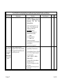
1
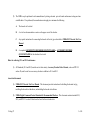
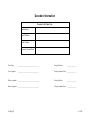
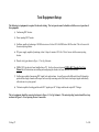
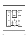
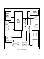
National Model Railroad Association (NMRA) Inc.
Digital Command Control (DCC)
Baseline Mobile And Accessory Decoder Test Procedures
Version 0.2
19 August, 1997
19-Aug-97
1 of 14
Test Rules and Assumptions
Rules for applying for a decoder conformance seal or requesting conformance testing:
1)
All applications for a decoder conformance seal must be accompanied by the following:
A.
A decoder for which conformance is to be tested.
B.
A complete set of user documentation.
C.
Any special instructions for connecting the decoder to the test jig as described in NMRA DCC Decoder Test User
Manual.
D.
Certification that the attached test procedures have been successfully completed by the manufacture prior to
submission for formal conformance testing.
E.
The manufacture must provide evidence that the decoder complies with the FCC Part 15 rules. Please attach a copy
of the FCC report.
F.
A completed LOCOMOTIVE DECODER QUESTIONNAIRE or ACCESSORY DECODER
QUESTIONNAIRE for the decoder to be tested.
2)
The NMRA may be petitioned to aid a manufacturer by testing a decoder prior to formal conformance testing on a time
available basis. If so petitioned, the manufacture must supply at a minimum the following:
A.
The decoder to be tested.
B.
A set of user documentation or notes on the proper use of the decoder.
C.
Any special instructions for connecting the decoder to the test jig as described in NMRA DCC Decoder Test User
Manual.
D.
A completed LOCOMOTIVE DECODER QUESTIONNAIRE or ACCESSORY DECODER
QUESTIONNAIRE for the decoder to be tested.
Rules for achieving S9.1 and S9.2 conformance
1)
All Standards (S9.1 and S9.2) must be met in their entirety. Accessory Decoder Packet Format, section of RP 9.2.1
section D, must be met for an accessory decoder in addition to S9.1 and S9.2.
Associated documents
1)
NMRA DCC Decoder Test User Manual. This document provides instructions for building the decoder test jig,
installing the decoder test hardware, and installing the decoder test software.
2)
NMRA Digital Command Control Standards & Recommended Practices. This document contains standard S9.1,
S9.2, and RP 9.2.1 section D which are the basis for these decoder tests.
19-Aug-97
3 of 14
Decoder Information
Decoder Unit Under Test:
Manufacturer:
Model Number:
Serial Number
Firmware Version/Date:
Tester Name:
_____________________________________
Testing Start Date:
_________________
Tester Signature:
_____________________________________
Testing Completion Date: _________________
Witness (optional): _____________________________________
Testing Start Date:
Witness Signature: _____________________________________
Testing Completion Date: _________________
19-Aug-97
_________________
4 of 14
Test Equipment Setup
The following test equipment is required for decoder testing. The test operator must be familiar with the correct operation of
this equipment.
1) Conforming DCC booster.
2) Noise injecting DCC booster.
3) Oscillator capable of producing a 100 KHz sine wave of at least 10 Volts RMS into a 600 Ohm load. This is for use with
the noise injecting booster.
4) DC power supply capable of producing at least 1 Amp of current at 20 Volts. This is for use with the noise injecting
booster.
5) Decoder test jig as shown in Figure 1: Test Jig Schematic.
6) NMRA DCC decoder test board installed into a PC. See the reference document NMRA DCC Decoder Test User
Manual for full instructions on installing and configuring the decoder test board hardware and software.
7) Oscilloscope capable of measuring DCC signal levels and risetimes. An oscilloscope with differential A and B channels is
preferred but a single channel oscilloscope can be used by measuring each of the booster track output signals individually
with reference to system ground.
8) Voltmeter capable of reading peak decoder DCC signal input AC Voltages and decoder output DC Voltages.
The test equipment should be connected as shown in Figure 1: Test Jig Schematic. The noise injecting booster should be set up
as shown in Figure 2: Noise Injecting Booster Connections.
19-Aug-97
5 of 14
GND (1)
DCCA (2)
DCCB (3)
GND
INA
INB
PC
TRACK+
TRACK+
TRACK-
TRACK-
Booster
Decoder
2200 Ω
MOTOR +
[Out 1 left]
IN0A (9)
+
47 uFd
20 Volt
100 Ω
5 Watt
+
IN0B (10)
2200 Ω
MOTOR[Out 1 right]
Figure 1: Test Jig Schematic
19-Aug-97
6 of 14
AC
20 Volt
Power
Supply
+
U
−
V
INA
C
INB
D
GND
Y
Peak AC
Voltmeter
COM
J
Noise
Injecting
Booster
TRACK+
100 Ω
5 Watt
K
TRACK+
X
OUT
Sine
Wave
Generator GND
Oscilloscope
System
Ground
Reference
Note:
B Channel
Is Optional
IOptional
A
B
Figure 2: Noise Injecting Booster Connections
19-Aug-97
7 of 14
Test Procedures
Equipment Setup For Manual Tests
1) For a mobile decoder, program the decoder for the proper address and 14 speed step baseline operation. The motor control variables should be set
to give the largest motor Voltage changes between speed steps possible with the minimum acceleration and braking momentum. The tests
assume that the locomotive decoder can go from half speed reverse to stop within one second of receiving an emergency stop command.
For an accessory decoder, program the decoder for the proper address. The accessory decoder should be programmed to keep the switch output
active for at least one second for the tests to work reliably.
2) Connect conforming booster as per Figure 1: Test Jig Schematic.
3) Start decoder test program in manual mode by typingC:\> send -m
for a mobile decoder or
C:\> send -d a -m
for an accessory decoder.
4) Enter appropriate decoder information when prompted.
5) Verify self tests have passed
19-Aug-97
8 of 14
Manual Decoder Tests
Standard/RP
S9.1 and S9.2.
Requirements
Decoder must respond to RESET
command defined in S9.2.
Test Action
1.
2.
S9.1 - S9.2 for a
mobile decoder.
RP 9.2.1 section
D, Accessory
Decoder
Packet Format
for an accessory
decoder.
Decoder must respond to all baseline
commands defined in S9.2 for a mobile
decoder or RP 9.2.1 section D for an
accessory decoder.
3.
4.
5.
19-Aug-97
Decoder Response
Pass
Fail
Enter the RESET command
>> r
at the prompt.
Verify that the decoder enters the
RESET state.
Enter the DCC packet command
>> d
at the prompt.
Verify that decoder responds to each
baseline command with an observable
change to its output.
Use the
>> s
and/or
>> f
commands to send each baseline
packet. Measure the decoder output
using the oscilloscope or Voltmeter.
Exit the test program by typing
>> q
at the prompt.
9 of 14
Decoder Setup And Automated Tests With The Conforming Booster
Standard/RP
Requirements
Test Action
Decoder Response
Pass
Fail
1.
S9.1 - S9.2 for a
mobile decoder.
RP 9.2.1 section
D, Accessory
Decoder
Packet Format
for an accessory
decoder.
19-Aug-97
Decoder is required to pass the
appropriate sections of the specification.
The program will automatically run the
tests and log the results.
Decoder should be programmed and
connected as specified in the manual
test section.
2. Connect conforming booster as per
Figure 1: Test Jig Schematic.
3. Start decoder test program in
automatic mode by typingC:\> send
for a mobile decoder or
C:\> send -d a
for an accessory decoder.
4. Enter appropriate decoder information
when prompted.
5. Verify self tests have passed.
6. The program will run tests for
approximately 12 hours and exit.
7. At the conclusion of the test, verify that
at least 95% of all packet acceptance
tests pass except for
‘pre 10 idle 0’ which is
allowed to fail.
8. Verify that 100% of the bad address
and bad bit tests pass.
9. Verify that 1T margin test is within
S9.1 limits.
10. Verify that the 1 bit duty cycle test is
within limits.
10 of 14
Equipment Setup For Automated Tests With Noise Injecting Booster
1) Decoder should be programmed and connected as specified in the manual test section.
2) Connect the noise injecting booster as per Figure 1: Test Jig Schematic and Figure 2: Noise Injecting Booster Connections.
3) Start decoder test program in manual mode by typingC:\> send -m
for a mobile decoder or
C:\> send -d a -m
for an accessory decoder.
4) Enter appropriate decoder information when prompted.
5) Verify self tests have passed.
6) Enter the DCC packet command
>> d
at the prompt.
7) For a mobile decoder, enter the commands to turn on the lamp output and set the motor output to ½ speed reverse. For an accessory decoder, turn
on output 1.
8) If the decoder supports separate power and DCC signal inputs, apply power per the manufacturers recommendation. Adjust the separate DCC
signal input to a level of 4 Volts peak using the front panel knob. Note: this is a signal of -4 Volts to +4 Volts peak to peak.
If the decoder has merged power and signal input leads, slowly reduce the noise injecting booster signal Voltage by turning the front panel knob
counterclockwise until the decoder ceases to work. Observe the peak Voltage at this point and then increase the peak Voltage by 1.0 Volt (2
Volts peak to peak). The decoder should be running normally at this point.
9) Enter the minimum and test Voltages arrived at in step 8. The minimum and test Voltage should both be 4 Volts peak for a decoder with
separate power and signal inputs. The minimum Voltage should be 1 Volt less than the test Voltage for a decoder with merged power and signal
inputs.
(Note: The peak Voltages entered below are ½ the peak to peak Voltages):
Minimum DCC Voltage For Operation(Vpeak):
Volts
DCC Test Voltage (Vpeak):
Volts
10) Add 100 KHz sine wave noise to the signal until the peak noise Voltage is 25% of the peak signal Voltage.
11) Verify that the rise and fall time switches are both set to ‘4’ for a rise and fall time of 2 Volts/usec.
19-Aug-97
11 of 14
12) Exit the test program by typing
>> q
at the prompt.
19-Aug-97
12 of 14
Tests With The Noise Injecting Booster And Decoder Input Leads In The Normal Position
Standard/RP
Requirements
Test Action
Decoder Response
Pass
Fail
1.
S9.1 - S9.2 for a
mobile decoder.
RP 9.2.1 section
D, Accessory
Decoder
Packet Format
for an accessory
decoder.
19-Aug-97
Decoder is required to pass the
appropriate sections of the specification.
The program will automatically run the
tests and log the results.
Equipment should be set up as
specified in Equipment Setup For
Automated
Tests
With
Noise
Injecting Booster.
2. Connect conforming booster as per
Figure 1: Test Jig Schematic with
decoder input leads in the NORMAL
position.
3. Start decoder test program in
automatic mode by typingC:\> send
for a mobile decoder or
C:\> send -d a
for an accessory decoder.
4. Enter appropriate decoder information
when prompted.
5. Verify self tests have passed.
6. The program will run tests for
approximately 12 hours and exit.
7. At the conclusion of the test, verify that
at least 95% of all packet acceptance
tests pass except for
‘pre 10 idle 0’ which is
allowed to fail.
8. Verify that 100% of the bad address
and bad bit tests pass.
9. Verify that 1T margin test is within
S9.1 limits.
10. Verify that the 1 bit duty cycle test is
within limits..
13 of 14
Tests With The Noise Injecting Booster And Decoder Input Leads In The Reversed Position
Standard/RP
Requirements
Test Action
1.
Equipment should be set up as
specified in Equipment Setup For
Automated
Tests
With
Noise
Injecting Booster.
2.
Connect conforming booster as per
Figure 1: Test Jig Schematic with
decoder input leads in the
REVERSED position.
Start decoder test program in
automatic mode by typingC:\> send
for a mobile decoder or
C:\> send -d a
for an accessory decoder.
Enter appropriate decoder information
when prompted.
Verify self tests have passed.
The program will run tests for
approximately 12 hours and exit.
3.
4.
S9.1 - S9.2 for a
mobile decoder.
RP 9.2.1 section
D, Accessory
Decoder
Packet Format
for an accessory
decoder.
Decoder is required to pass the
appropriate sections of the specification.
The program will automatically run the
tests and log the results.
5.
6.
Decoder Response
Pass
Fail
7. At the conclusion of the test, verify that
at least 95% of all packet acceptance
tests pass except for
‘pre 10 idle 0’ which is
allowed to fail.
8.
Verify that 100% of the bad address
and bad bit tests pass.
9. Verify that 1T margin test is within
S9.1 limits.
10. Verify that the 1 bit duty cycle test is
within limits..
19-Aug-97
14 of 14