1
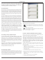
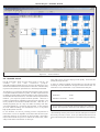
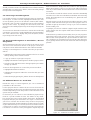
user manual
LokProgrammer
order number 53450
For Software Version from 2.4.0
January 2005
53450 LokProgrammer user manual V2.4.0 01/2005/2004
1
contents
Inhaltsverzeichnis
1.
Properties of LokProgrammer ......................................................................................................................................... 3
2.
System Requirements .................................................................................................................................................... 3
3.
Connecting the LokProgrammer ..................................................................................................................................... 3
4.
Installing the Software ................................................................................................................................................... 4
4.1 Starting the Program ..................................................................................................................................................... 4
5.
Program Functions ........................................................................................................................................................ 4
5.1 Assistant ...................................................................................................................................................................... 5
5.2 Supported Decoders / LokProgrammer ............................................................................................................................ 5
5.3 Main Menu .................................................................................................................................................................. 5
5.4 Decoder Settings ........................................................................................................................................................... 5
5.4.1 Reading out Data from a Decoder .................................................................................................................................. 6
5.3.1 Setting Addresses .......................................................................................................................................................... 6
5.3.2 Running Characteristics ................................................................................................................................................. 6
5.3.3 Motor Settings .............................................................................................................................................................. 7
5.3.4 DCC/ Analogue ............................................................................................................................................................. 7
5.3.5 Sound Settings .............................................................................................................................................................. 7
5.3.6 Functions ..................................................................................................................................................................... 8
5.3.7 Identification ................................................................................................................................................................ 9
5.3.8 Special Options ............................................................................................................................................................. 9
5.3.9 MFX-Settings ................................................................................................................................................................ 9
5.3.9 Writing Decoder Data ................................................................................................................................................... 9
5.3.10 Saving Decoder Data on Hard Disk ............................................................................................................................... 10
5.4 Adjusting CV’s ............................................................................................................................................................ 10
5.5 Virtual Cab Control ..................................................................................................................................................... 10
5.4 Sound Updates ........................................................................................................................................................... 10
5.4.1 Available Sound Files ................................................................................................................................................... 11
5.4.2 Sound Updates ........................................................................................................................................................... 11
6.
Compiling Sound Projects ............................................................................................................................................ 12
6.1 Concept of Sound Updates .......................................................................................................................................... 12
6.1.1 Sound Memory ........................................................................................................................................................... 12
6.1.2 Sound Sequence ......................................................................................................................................................... 12
6.1.3 Random Sounds ......................................................................................................................................................... 15
6.1.4 User-Sounds ............................................................................................................................................................... 15
6.2 S ound Projects ............................................................................................................................................................. 16
6.3 Loading / Saving complete Projects .............................................................................................................................. 16
6.4 S ound Slots in Detail ..................................................................................................................................................... 16
6.5 S elect / Remove Individual Sounds for Projects ................................................................................................................ 16
6.4.1 Suitable Sounds .......................................................................................................................................................... 17
6.4.2 Listening to Sound Fragments ...................................................................................................................................... 18
6.5 Assign Sound Fragments to Sound Slots / Reverse Assignments ...................................................................................... 18
6.6 Additional Entries for Sound Slots ............................................................................................................................... 18
6.7 Write new Sound Files onto the Decoder ...................................................................................................................... 19
7.
Customer Service / Support .......................................................................................................................................... 19
Copyright 1998 - 2005 by ESU electronic solutions ulm GmbH & Co KG. Electrical characteristics and dimensions are subject to change
without prior notice. All rights reserved. ESU may not be held responsible for any damage or consequential loss or damage caused by
inappropriate use of the product, abnormal operating conditions, unauthorized modifications to the product, etc.
Not suitable for children under 3 years of age. Inappropriate use may result in injury due to sharp points and edges.
Märklin® is a registered trademark of the company Gebr. Märklin® und Cie. GmbH, Göppingen, Germany.
2
53450 LokProgrammer user manual V2.4.0 01/2005
Properties of LokProgrammer
1. Properties of LokProgrammer
Thank you for purchasing the LokProgrammer set 53450. The LokProgrammer is an accessory for the use with LokSound Decoders.
2. System Requirements
In order to use this software you need a commercially available PC
with the following requirements:
LokProgrammer consists of two core components: An interface
module, that represents the physical connection between the PC
and the locomotive, and the software, that can be run on any PC
using MS Windows.
This combination allows you to easily manipulate and adjust the
many features and properties of LokSound decoders with your PC.
Never was it easier to program a digital decoder than with LokProgrammer. Thanks to the graphic interface of MS Windows you
can achieve the optimal adaptation of LokSound decoders even if
you have very little or no experience in programming digital decoders.
LokProgrammer also allows you to modify all sound fragments
and sound effects stored on the decoder as often as you desire.
ESU provides over 80 (!) different sound files. You almost certainly
will find the right sound for your locomotive.
This manual describes in detail how to modify sounds and which
methods to use to achieve the desired results.
Please adhere to the installation guidelines to assure that your
LokProgrammer software operates to your full satisfaction!
• Microsoft Windows 98, 2000 or XP (not Windows NT)
• CD-ROM drive
• Serial interface
• Audio card
To connect LokProgrammer to the PC a serial port is required. If
your PC does not have a serial port you could use a commercially
available cable with a USB adapter. In order to modify any sound
files with this software an Audio Card must be installed. All cards
with a Windows driver are suitable.
3. Connecting the LokProgrammer
The LokProgrammer has to be connected as shown in Figure 1:
Use the serial cable provided to connect the LokProgrammer to
any available COM port of your PC. Which port you select is
immaterial.
There are two options for the power supply:
• Use the power pack with mains plug provided with the LokPro
grammer. Wire the output of the power pack to the power supply
terminals of the LokProgrammer as per Figure 2.
ESU electronic solutions ulm GmbH & Co KG, January 2005
• Use the AC power output of a model train transformer and wire
it to the screw terminals. We recommend this option for
programming large gauge locomotives, particularly gauge 1
models.
Do not connect both terminals at the same time. This could
lead to the destruction of the LokProgrammer!
programming track
Programmer
serial cable
power supply
BPC
figure 1:Wiring diagram
53450 LokProgrammer user manual V2.4.0 01/2005/2004
3
Installing the Software / Starting the Program
-
+
figure 2: Connection schematic of plug
The green LED lights up once power is connected.
Connect the sockets Track1 and Track2 of the LokProgrammer with
the programming track.
Please make sure that the programming track is completely
isolated from the rest of the layout!
The two LEDs on the LokProgrammer indicate the following:
Green LED: Is lit continuously when supply voltage is available.
Is blinking when the LokProgrammer receives data
from the PC.
figure 3: Internet-Update
Yellow LED: Blinks quickly when voltage is applied to the
programming track and data is transferred via the
programming track. Blinks slowly if the LokProgrammer detects a high current and has subsequently
disconnected the programming track.
The software checks for updates after each start-up. If you do not
want to check every time you start the programm – perhaps because
you do not have a permanent Internet connection – please activate
the option „do not show this dialogue when starting the program“.
4. Installing the Software
Once you have deactivated the automatic search for updates you
can still look for updates by calling up „Internet update“ either in
the file menu or in the menu „LokProgrammer“.
Make sure that the LokProgrammer is connected as described above
and is ready for use.
As soon as you insert the CD-ROM into the drive the installation
program is starting automatically. Should this not be the case click
onto the „Start“ button in the tool bar and select „Run“. Then type
„x:\setup.exe“ and click OK, whereas „x:“ stands for the CD-ROM
drive (usually „D“):
After a short while the program should start. Follow the instructions
on the monitor and wait until the program is installed on the hard
disk.
Privacy Protection:
ESU guarantees that no information will be downloaded from
your PC to the ESU website. Data transmission is strictly limited
to sending data form the ESU home page to your PC. Your
personal data are protected at any time.
4.1 Starting the Program
The installation program creates an entry in the start menu. Click
on „Start-Program-LokProgrammer2-LokProgrammer“, to start the
program.
4.2 Internet Update
The Lokprogrammer software contains a function for automatic
updates. If desired, the program can automatically call up the ESU
website and check for any new program versions. Such updates
can be automatically downloaded and installed if so desired. Thus
it is extremely easy to always have the latest version.
This update is automatically executed after the very first program
start. A window as shown in Figure 2 pops up.
If a later version is available you can download and install it simply
by a click on „Update“.
5. Program Functions
The software fulfils several tasks:
• Setting / changing of any parameter of ESU decoders: All options
can be comfortably set with your PC. You will never have to
enter CV’s on your handheld controller or central command
station! LokProgrammer takes care of all these tasks for you.
• Changing of sound data stored on your ESU LokSound module:
It is possible to modify all sound data at any time, even compiling
new sound project! Thus you can compile your own sounds
using anything as source that can be stored on your PC: e.g.:
running noises, music, speech, etc. Let your imagination soar
to new heights!
• Testing of new ESU decoders: You can test your decoders directly
on the programming track by means of the virtual cab throttle
without having to walk over to your digital layout.
The varying tasks of the programm are organised in different menus.
4
53450 LokProgrammer user manual V2.4.0 01/2005
Assistant
5.1 Assistant
As soon as the software is started a small window appears on the
screen. Here you can select and call up the most important tasks of
the program. The assistant helps you to call up and execute the
desired tasks very quickly.
LokSound V3.0, LokSoundXL V3.0, LokSound2, LokSoundXL V2.0,
LokPilot, LokPilotDCC, LokPilotXL, LokPilotXL DCC, LokSound mfx.
The software is subject to continous improvement. To assure
that you are working with the latest version we recommend
you call up the Internet-update-function regularly. Whenever
available, we offer the latest version with expanded functionality
and bug fixes.
The appearance of the programm on the screen may vary depending
on the features offered by the different decoder versions. Thus not
all features described here may be available. Please always refer to
the user manual of your decoder.
5.3 Main Menu
Figure 5 shows the main menu of the LokProgrammer software
with the following key components:
• Virtual cab throttle: for easy testing of decoders
figure 4: Assistant Dialog
• Change CV’s: for changing individual CV’s of a decoder, provided
it supports DCC.
Depending on your selection you can read out data in order to
comfortably study and modify the settings as desired. You can also
completely change the sound data, for instance in order to change
from a steam locomotive to a diesel engine. Or you may compile a
completely new sound project.
• Decoder: Full graphic display for programming ESU decoders
quickly and comfortably
• Sound: for changing existing sound projects and compiling new
ones for your LokSound-decoders.
5.4 Decoder Settings
5.2 Supported Decoders / LokProgrammer
The LokProgrammer software version 2.5.0 only supports the LokProgrammer 53450 „LokProgrammer V3.0“. Currently it does not
operate with older types such as for instance 50450.
All settings relating to the running features of the decoder are
contained in this register. Please note, that the register „Decoder“
is empty when you start the program. You first have to compile a
new „project“, read out a decoder or load an existing project from
the hard disk. Projects represent all data on a decoder.
Depending on the version of the LokProgrammer not all decoders
may be supported. Version 2.5.0 supports the following ESUdecoders:
figure 5: Main screen
53450 LokProgrammer user manual V2.4.0 01/2005/2004
5
Reading out Data from a Decoder / Setting Addresses/ Running Characteristics
5.4.1 Reading out Data from a Decoder
Before changing any data it is advisable to first read out the data.
Place the locomotive on the programming track and make sure the
track is connected properly.
Afterwards you click on „Read out CV’s from decoder“ on the tool
bar at the top of the screen. Alternatively you may select „Reading
decoder data“ from the menu „Programmer“. The programm starts
the read out immediately (also refer to Figure 6). Please be patient,
this process may take up to two minutes. The progress is shown in
the progress bar.
programm long addresses (4-digit addresses) or short addresses.
Please note that all settings in this menu relate to NMRA DCC
operation. For the Märklin / Motorola-protocol a separate menu
„Märklin address“ can be entered. The DCC Consist Address is very
useful for multi-headers in DCC mode. Some decoders accept a
second address in Motorola-mode to allow you to activate function
F5 to F8.
5.3.2 Running Characteristics
Here you can adjust further parameters for smooth operation. In
DCC mode you first have to set the speed steps to 14, 28 or 128 or
if the decoder should detect the correct number automatically.
If you tick „Reverse mode“ the direction of travel as well as the
directional headlights are opposite to normal.
The slide control enables you to set the acceleration / deceleration
time in seconds. This is the time the locomotive needs to accelerate
from stop to maximum speed or vice versa.
Under „Adapting acceleration or deceleration“ you may add or
subtract extra time from the above setting.
figure 6: read decoder data
In this menu you can also select the permitted brake modes and
under „Trim“ you can adjust the maximum speed for forward or
reverse running.
If the programm cannot read the data an error message will be
displayed.
This could have several reasons:
• The locomotive is not sitting properly on the programming track
or the track is not connected to the LokProgrammer.
• The decoder has not been wired correctly – particularly the motor
connections.
• The decoder may be faulty.
5.3.1 Setting Addresses
All settings related to the locomotive address are changed in
„Address“: Depending on the type of decoder you may be able to
figure 7: setting the address
6
figure 8: running properties
53450 LokProgrammer user manual V2.4.0 01/2005
Motor Settings/ DCC/ Analogue / Sound Settings
5.3.3 Motor Settings
5.3.4 DCC/ Analogue
Here you can set the tact frequency for motor control.
Here you set the desired analogue properties of the decoder. In
analogue mode load control is not active. Therefore you may adapt
the starting and maximum voltage separately to the motor (!) for
AC or DC operation or your analogue controller by means of the
slide control.
Under „Load control“ you can turn on or off load control and set
the reference voltage and control parameters K and I.
The effect of load control can also be adjusted: Here you determine
if load control should be active up to maximum speed (100%) or
only up to a certain speed step. Thus a locomotive may run
smoothly at low speeds due to load control while prototypically
slowing down from high speeds while on a gradient on the main
line.
The number of values and the values themselves depend on the
type of decoder. For useful values please refer to the manual of
your decoder.
Under „Speed curve“ you may decide if you want to operate
according to a three-point-speed curve or a speed table. Depending
on your choice you may enter the desired speed steps individually
in the field below to programm the most prototypical dynamics.
Both the three-point-speed curve as well as the speed table in 14 or
28 speed steps are active in all operating modes: regardless if you
run DCC with 14, 28 or 128 speed steps or Motorola (14 speed
steps) or mfx; the selected speed curve will always be adapted
(interpolated) to the operating mode.
Further more you can select which functions should be active in
analogue mode.
5.3.5 Sound Settings
Here you can adjust certain parameters that relate to the sound
effects of the decoder.
In order to understand how LokSound decoders work it is important
to bear the following facts in mind: The sound fragments contained
in the respective project file determine what kind of sound is stored
on the decoder (steam, diesel, etc.). Here you adjust how stored
sound fragments are influenced by the LokSound module. These
settings have to comply with the type of sound recorded. Otherwise
the result may be sounds from a steam engine while the decoder is
set to diesel mode, in other words the sounds will make no sense
at all.
First you decide if you want to program a steam, diesel or electric
locomotive. Then – subject to your choice – you may set parameters
to synchronise the exhaust chuffs of a steam engine with the revs
of the drivers: either by connecting an external wheel sensor or
speed step dependent. If you prefer the latter you can adjust the
interval between two exhaust chuffs for the lowest speed step resp.
for speed step 2 (thus determining the rate of change with increasing
speed). For useful values please refer to the manual for your decoder.
In the field „Speed of running noises“ you enter the revs of the
diesel engine at the lowest (MIN) and highest (MAX) speed step. It
is given in percent. 100% means: the speed of the power plant of
the diesel engine is replayed at the same speed as it was recorded.
200% therefore means twice the speed (double „sound revs“).
The slide controls in the field „Random sounds“ influence the time
interval between any such sounds. These could be escaping steam,
fireman Fred, water pumps, etc.
The volume of these sounds may be adapted to the speaker with
the slide control.
Please also refer to the manual of your LokSound decoder.
figure 9: motor settings
53450 LokProgrammer user manual V2.4.0 01/2005/2004
7
Functions
figure 10: sound settings
5.3.6 Functions
Here you can assign the functions to the different function buttons.
Depending on the type of decoder the functions F1 to F12 may be
available. Please remember, that Märklin only offers the buttons F1
to F4. With the aid of a second address (refer to 5.3.1) you may
also activate buttons F5 to F8.
The feature of switching acceleration / deceleration on and off
separately with a function button deserves a special mention. The
same goes for the shunting mode. It effectively reduces the speed
to half. These features are particularly useful for prototypical shunting
movements.
Figure 10 provides an overview of the options available:
Subject to the decoder type different lighting effects may be
activated on most function outputs such as blinking or dimming.
The lamp supply is then pulsed for reducing their brightness. The
blinking sequence and the duration of the „on“ and „off“ period
can be adjusted separately with a slide control.
In order to assign a function to a certain button you place a tick at
the appropriate field in the table, namely where the column
„Function button“ and the row „Function“ cross each other.
Please remember, that function mapping is stored in CV’s. Therefore
you should always read out the decoder data prior to implementing
any changes to assure that you are aware of the current assignment
of functions.
Not all options are available on every decoder type (subject to the
decoder version) and some theoretically possible combinations may
not be practical. Such „impossible“ combinations are shaded grey.
It is possible to assign several functions to one button. You could
for instance trigger a sound sequence every time function AUX 1 is
activated. However, you cannot assign two different sound effects
to the same button.
8
53450 LokProgrammer user manual V2.4.0 01/2005
Special Options/ MFX-Settings
Preserve Direction activates the so-called directional bit that assures
on Märklin layouts that the current direction always matches the
direction on the layout.
Persistent Function stores the status of all function buttons assuring
the same status after a power cut.
Persistent Speed saves the current desired speed and accelerates
the locomotive to that speed after a power cut. With Persistent
Speed active the locomotive accelerates with the pre-set acceleration,
if Persistent Speed is turned off the locomotive will accelerate as
fast as possible.
If these options are actually available depends on the decoder
firmware amongst others.
5.3.9 MFX-Settings
Here you may enter the name of the locomotive or a symbol when
using mfx decoders.
figure 11: function mapping
5.3.7 Identification
Here you can read the manufacturer’s ID and the version number.
Some decoders offer the option for entering two variables (e.g.:
user ID).
figure 13: MFX settings
5.3.8 Special Options
In some decoders special options (storing additional data) can be
activated.
5.3.9 Writing Decoder Data
After you have modified all settings according to your own personal requirements and as described above, these settings have to be
stored on the decoder. Please do not forget to implement these
steps since all settings will be lost after shutting down the program
if they have not been transferred to the decoder.
Click onto „Write CV’s onto decoder“ on the tool bar or select
„Write decoder data…“ in the main menu.
The new settings will replace all previous ones; they will be
overwritten.
figure 12: special options
53450 LokProgrammer user manual V2.4.0 01/2005/2004
9
Saving Decoder Data / Adjusting CV’s / Virtual Cab Control
5.3.10 Saving Decoder Data on Hard Disk
Besides transferring the data onto the decoder you can also save
them onto the hard disk of your PC. Thus you can establish an
archive containing all data of each locomotive. We call such data
files „projects“.
All CV’s are stored together with all sound files in one project file.
5.4 Adjusting CV’s
In the register „Adjusting CV’s“ you can read and write individual
CV’s.
Enter the number of the CV’s to be read or written in the field on
top. For reading press button „Read CV“ and the result will be
displayed on the left of the button: either in binary or in decimal
format.
figure 15: Virtual Cab control
programming track will be cut off. The yellow LED on the LokProgrammer blinks to indicate this status. In this case shut down the
virtual cab and re-start it once again.
All other functions in this register are straightforward: You may
enter the address and speed steps. Please note the speed step setting
has to coincide with the setting of the decoder.
The slide control allows you to run the locomotive. For control
purposes the speed step is displayed as well.
The LokProgrammer can run locomotives in DCC-format; as from
version 2.5.0 also in Motorola-format. The LokProgrammer hardware
cannot handle mfx.
Please note, that the LokProgrammer is not intended as a
substitute for a controller or a digital command station: due
to the limited power you will never be able to run more than
one locomotive at any time. It is meant as a quick means of
testing of any newly programmed locomotive.
figure 14: Reads/ Writes CVs
If you want to enter a value for a CV, first enter the number of the
CV in the upper field and then the value in the lower field. After
clicking on „Write CV“ the new value will be written and saved.
It is also possible to read out the manufacturer’s ID. Simply click
on „Read data“.
Please note, that any changes you make in this window will not
affect the graphic display („Decoder“). To update the display you
have to read out all data from the decoder once again (refer to
chapter 5.3.1).
5.5 Virtual Cab Control
Here you may test your decoder. This applies to all function buttons
and also running commands. Thus you can actually run your
locomotive on the programming track!
However, there are some limitations: The LokProgrammer limits
the current to about 400 mA. If the motor draws a higher current
the overload protection will be activated and the power to the
10
5.4 Sound Updates
Sound files on any LokSound decoder may be deleted and be
replaced by new data. In 1999 LokSound „classic“ was the world’s
first decoder to offer that unique feature.
Thus it is possible to convert a steam engine to a diesel or electric
locomotive or vice versa at any time.
The decoder has a memory chip with 8 MBit storage capacity. This
provides approximately 65 seconds of sound data. Perhaps you
may ask how that is possible, since you can hear continous sound
from your engine once you have turned on the running sound. The
chip only stores a small fragment of the sound of the diesel engine
(about half a second). This fragment is replayed in a continous
loop creating the impression of a continous sound. Such „tricks“
help to utilise the limited storage capacity to the optimum.
Within the chip any number of sound fragments may be stored.
The location and duration of each fragment is registered in a table.
The fragments are also numbered to find them quickly when
needed.
53450 LokProgrammer user manual V2.4.0 01/2005
Sound Updates
The LokSound decoder also contains a „Sequence plan“ containing
all relevant information regarding when which sound fragment
has to be replayed. In conjunction with the sound files this represents
a „Rule book“, that tells the decoder what exactly it has to do, and
when.
5.4.1 Available Sound Files
Compiling sound projects for LokSound decoders is quite complex.
Therefore ESU electronic solutions ulm GmbH & Co KG provides
more than 80 (!) completely configured sound files (project files).
Thus you may choose the right sound for almost any locomotive
class or type. Due to the LokSound technology you can record as
many sound files for as long as you like until you arrive at your
ultimate sound.
5.4.2 Sound Updates
A Sound Update for a LokSound decoder is best carried out with
the aid of the Assistant. Restart the program and select the second
point „Sound Update“ in the menu „Assistant“ and click „Continue“.
Also refer to figure 4.
The following dialogue appears:
figure 17: COM-Port selection
First the CV’s of the decoder will be updated and then the sound
files.
Completion of this process is indicated by a small pop up window
appearing on the screen.
figure 16: Update: Selection of projectfile
Click on „Search“ and select one of the sound files from the list.
Such sound files exist for all sound projects provided by ESU.
Click „Continue“ again and confirm to which serial port the LokProgrammer is connected (also refer to Figure 17). Click „Continue“
once more to start the update. Please note, this may take up to 6
minutes.
53450 LokProgrammer user manual V2.4.0 01/2005/2004
figure 18: Soundupdate
11
Compiling Sound Projects
6. Compiling Sound Projects
6.1.1 Sound Memory
Even the very first LokSound „classic“ offered the feature of rerecording sounds as the first and only product in its class as early
as 1999. Since then the LokSound decoder has become the platform
for a host of railway related sound effects. With this universal and
extremely flexible concept it is possible to record not just engine
noises, but also speech and music. Let your imagination sore to
new heights.
Depending on the version of the decoder the flash memory has a
capacity of up to 8 MBit. This is sufficient to store approximately
65 seconds worth of sound in it.
In order that you can fully utilise the manifold options of the
LokSound decoder in terms of sound the following chapter outlines
first the general concept of the sound module before explaining
step by step how to work with the software. Please read this
introduction before you start compiling new sound projects.
Without understanding the concept you may not recognize and
utilize the potential of this program.
In order to achieve optimal results it is advisable to practice a bit at
first. However, the experience of your own sounds for a specific
engine is certainly worth the effort. …
We describe the concept for LokSound decoders, version 3. Older
LokSound2 or LokSound „classic“ decoders offer fewer functions,
the principle, however, remains the same.
You may store as many sound fragments, as you like within the
flash memory. Every fragment will be recorded in a list containing
information on the exact location and length within the memory.
These sound fragments are also numbered so they can be found
and assigned later on.
6.1.2 Sound Sequence
After you have stored various sound fragments in the flash memory
you have to determine when a certain sound should be played and
for how long.
All necessary information is contained in the sequence plan. This
consists mainly of a table. The number of entries depends greatly
on the type of engine (steam, diesel, electric). You make your choice
by selecting the appropriate field at the top of the screen (see
Figure 20)
Selects a steam engine
Selects a diesel engine
Selects an electric locomotive.
For electric locomotives another two fields are available:
6.1 Concept of Sound Updates
Shows the sequence plan for the motor sound
LokSound decoders contain a flash memory in which all sound
data are stored in digital form. Individual sound fragments may be
stored separately. The data is transferred with the aid of the LokProgrammer from the PC to the decoder.
LokSound decoders contain a sequence for replaying various sounds.
This sequence determines which sounds are played at any specific
point in time and also what sound effect should be triggered by
pressing a function button, or if and how often and for how long
sounds like shoveling coal, hissing steam (pop valve) or the air
pump should be played while the locomotive is stationary. While
the sequence as such is already contained in the software you have
to enter the desired sound fragments in the various positions with
your PC. You will find this plan under „Sequence“ in the menu
„Sound“.
Shows the sequence plan for the separate blowers.
Further settings can be adjusted depending on the type of
locomotive – steam, diesel or electric – within the dialogue box as
shown in Figure 21
1 Diesel start
2 Diesel stop
Soundslot
3 Diesel moving
Soundslot
4 Diesel idling
Sound Off
Soundslot
Soundslot
Running
noise
Idle
5 Horn#1
Soundslot
6 Bell
Soundslot
Soundslot
Soundslot
7 Whistle
8 Steam release
Geräuschspeicher
sound sequence
figure 19: Sound memory and sound sequence
12
53450 LokProgrammer user manual V2.4.0 01/2005
Compiling Sound Projects
figure 20: sequence plan
Generally the sequence plan is structured as follows:
The LokSound decoder knows three main states of operation:
• In status „M“ (=“Mute“, „Sound off“) the engine is stationary
and the sound module is turned off.
• In status „S“ (=“Stationary“) the locomotive is still stationary
but the sound module has been turned on. At this point a
diesel engine would have been started and would idle.
• In status „D“ (=“Drive“, or „Running“) the locomotive is moving
and the appropriate sounds would be heard. Depending on the
type of LokSound decoder up to 10 „D“-modes are available.
Thus you can define 10 different „Drive“-modes.
figure 21 : options for „steam“ sequence
53450 LokProgrammer user manual V2.4.0 01/2005/2004
13
Compiling Sound Projects
• Status „A“ (=“Acceleration“) is reached whenever the engine
accelerates rapidly. Here you can replay particularly strong noises.
Up to 10 „A“ -modes are available.
• Status „CX“ („Idle“) is reached whenever the throttle is turned
down and the engine is coasting.
The different modes are connected by arrows and thus represent
the changes of activity that may be reproduced. It is possible to
assign sound fragments to each of the three modes (positions) as
well as to the changes from one to the other. For this purpose a
number of sound slots have been assigned to the various positions
respectively for the change from one to the other. You can now
enter a number of sound fragments into these sound slots. These
entries represent one sound fragment each, which is stored in the
flash memory. Whenever the LokSound module changes from
one basic state to another then the sound fragments entered into
the appropriate sound slots will be replayed. Do you want to
prevent generating any sound at a certain position or change of
position you simply do not enter a sound fragment in the
appropriate sound slot.
When simulating a steam engine you may store up to four chuffs
to represent 2 – 3 – or 4-cylinder locomotives. The exhaust chuffs
will be played in sequence. The time interval between the chuffs
can either be synchronized to the speed steps or can be controlled
by means of an external sensor attached to the driver axle. Please
refer to chapter 5.3.5 for the appropriate settings. The number of
cylinders has to be set in „Options“ (refer to Figure 21).
• Sound Slot „DA“ has two positions for sound fragments that
will be played during the transition from „Drive“ to „Accelerate“.
For steam engines these sounds will also be played during the
transition from „A“ to „D“.
• There is a special Sound Slot „AD“ for diesel and electric
locomotives.
• Sound Slot „D“ is related to the „Running noise“ and again has
a capacity of four sound slots. As with Sound Slot „A“ up to
four exhaust chuffs can be replayed if simulating a steam engine.
They are repeated in sequence. The sound fragments in Sound
Slot „D“ are played whenever the engine has reached its normal
travelling speed.
Empty sound slots are shown in white while sound slots with
sound fragments are displayed in blue.
For diesel engines it is recommended to enter the normal running
noise of the diesel.
The various sound slots have a different purpose / effect depending
on where they are located.
• Sound fragments in Sound Slot „CX“ are replayed whenever the
locomotive is braking or stopping. Similar to Sound Slot „A“
where the set values for acceleration are taken into account the
set deceleration influences the performance.
• Sound Slot „MS“ is allocated to the change from „Sound off“ to
„Stationary sound“ and has sufficient space for two sound
fragments. Here you would enter the sound fragments that
should be played when the sound module is switched on. For
instance for a diesel engine you would store the starting noise
of the diesel. The two possible entries that will be played one
after the other allow a two part starting noise; first the noise
from the compressor then the actual start of the engine.
When simulating a steam engine two (resp. three or four) soft
exhaust chuffs or some rattling from the drivers should be entered
here (coasting steam engines make little noise). For a diesel
simulation a soft diesel sound should be entered.
• Sound Slot „S“ is directly assigned to „Stationary“: two entries
are possible and in case of a diesel engine it should contain the
idling noise of the diesel. It is important to be aware that all
sound fragments entered into sound slot 2 will be played in
sequence and in loop mode. This assures that the noise of the
diesel can be heard as a continuous sound even so the actual
sound fragment is only parts of a second long. When simulating
a steam engine in Sound Slot „S“ you would normally only
enter a soft hiss to simulate the continuously escaping steam
representing a „leaking“ boiler.
• There is an additional Sound Slot „CD“ for diesel or electric
engines, to allow for a sound simulating the change from a
coasting motor to an accelerating motor whenever the throttle
is opened up again.
• Sound Slot „SD“ between „Stationary“ and „Drive“ offers space
for two entries. The sound fragments entered here will be played
when the locomotive starts moving. Here the pop valve could
be blown.
• Sound fragments in Sound Slot „A“ will be played during the
acceleration phase of the locomotive. In this context acceleration
means that the actual speed of the locomotive is lower than the
desired speed. Example: the acceleration time of the locomotive
has been set to ten seconds. The locomotive runs slowly, then
you turn the throttle to maximum speed. The locomotive will
now – according to the preset time – accelerate slowly. During
this phase only the sounds in Sound Slot „A“ will be played.
This allows variations of the sound and to store particularly strong
exhaust chuffs or a noisier diesel during acceleration. The same
rule applies as before, namely that if you have entered several
sound fragments they will be played one after the other (1, 2,
3, 4) and then again and again in loop mode (1, 2, 3, 4, 1, 2,
3, 4,).
14
• In Sound Slot „DC“ you can enter up to four sound fragments,
for diesel or electric locomotives just one. They are replayed just
once during the transition from „Drive“ to „Stationary
• The sound in Sound Slot „CS“ is played once during the transition
from coasting to stationary. Perhaps this could be an air pump.
Should you not wish to utilise the feature of having separate sounds
for acceleration and brakes (perhaps because the required sound
fragments are not available) then you enter in the Sound Slots „A“
and „CX“ the same sound fragments as in Sound Slot „D“. Sound
Slot „D“ must have an entry; otherwise no engine noise will be
heard.
• Finally two sound fragments in Sound Slot „SM“ are replayed
during the transition between the statuses „S“ and „M“. For
diesel engines enter the noise of the dying engine and perhaps
the hiss of escaping air.
The number of speed steps has to be selected with a button at the
top of the sequence plan: simply select the desired number of
speed steps from the table.
53450 LokProgrammer user manual V2.4.0 01/2005
Compiling Sound Projects / Random Sounds/ User - Sounds
figure 22 : random sounds
6.1.3 Random Sounds
6.1.4 User-Sounds
There are a total of 16 possible sound slots as shown in Figure 22.
Separate sounds for a stationary or moving engine can be entered.
These sounds will be replayed randomly. These could be fireman
Fred, escaping steam (pop valve) air pumps, water pumps, etc.
The sequence occurs as follows: The LokSound decoder selects
within the pre-determined interval one of 8 possible sounds and
replays it. Which part is played exactly when cannot be predetermined. This results in ever changing sequences of such sounds.
The time intervals can be adjusted with two CV’s as per chapter
5.3.5
In addition to sound played depending on the status, LokSound
decoders can play other sounds activated with a function button.
As per Figure 23 a total of 16 sound slots are available for this
purpose.
You can enter a sound sequence in each of these Sound Slots,
triggered almost by any function button. Furthermore you can select
the mode of the function button, either to play the sound whenever
the button is pressed or to play it continuously as long as the
button is pressed.
Sound slots 14, 15 or 16 may have a special meaning: please refer
to Figure 21: if a special function such as squealing brakes are activated
then sound slot 16 is used for the braking noise.
figure 23 : sound effects activated by function keys
53450 LokProgrammer user manual V2.4.0 01/2005/2004
15
Sound Projects
In this context „Stop Sound“ indicates a noise that is played after
the engine has stopped (e.g.: the air pump of a steam engine, since
normally air is required for braking), while the noise of the shunts
would be appropriate for an electric locomotive.
6.2 Sound Projects
All sound data as well as the sequence plan containing all sound
slots and sounds to be activated by the function buttons can be
transferred from the PC to the LokSound module. However, the
reverse is not possible. That means, that all data will be stored in
the LokSound decoder according to the settings you have entered
and stored previously but you cannot read out the sound
information.
In order to enable you to read out sound files you can simply store
these files on the hard disk of your PC. In practice this means that
all data of the flash memory, the sequence plan as well as the
various sound slots will be saved to the hard disk before you transfer
the data to the LokSound module. Thus you have an exact copy of
all data on the hard disk that you can retrieve at any time and
modify as desired. All you have to do is remember which data file
on the hard disk contains the data for which decoder respectively
engine – assuming you have more than one LokSound decoder…
The data files, which you store on the hard disk, are so called
project files. We call the process to compile a new set of data for
a specific engine a project. Now you will learn how you can open
already completed projects, how to modify them and save them
again and also how to select specific sound fragments or sound
files and include them in your own personal projects.
In addition to all sound data files you can also save all CV settings
i.e. address, acceleration, etc. in your project file. Thus you can
create a specific file of all the settings for a specific locomotive and
save it to your hard disk.
figure 24 : sound slots in detail
Each Sound Slot consists of three parts
• Start: Here you could enter the starting sound of a steam whistle.
• Middle: for the middle part of the sound that can be looped
(optional).
• End: for the end of the whistle.
Thus you can use different sound fragments for each of the three
parts that will be played in sequence.
6.5 Select / Remove Individual Sounds for Projects
6.3 Loading / Saving complete Projects
In order to load or open a new project click onto „Open“ in the
„File“ menu and select the desired file. Should you only be at the
beginning of your „experiments“ with LokProgrammer we
recommend to use one of the data files provided on the CD ROM
that is supplied with LokProgrammer. This contains a number of
different steam and diesel engine sound projects that are an excellent
starting point.
If you want to save changes you have made in the sound project
simply click „Save“ or „Save as“ in the „File“ menu depending on
whether you want to override an existing project or if you want to
create a new project under a new name.
ESU-Project files have the ending „*.esu“
But how do you enter new sound fragments in the flash memory?6.5
Geräusche für Projekte auswählen / abwählen
Figure 25 shows the display on the monitor. The column on the
lower right contains all sounds to be entered into the sound slot.
The column on the lower left shows a file tree exactly as it would
be displayed in the Windows Explorer. This file tree also shows
audio files. They could be *. wav-files, or *.esu files. If you click
onto an ESU-file, it will be enlarged and shows the sound fragments
stored in the project file.
In order to enter one of the sound files that may be either on your
hard disk or the CD ROM provided into the list of sound files
proceed as follows:
• Highlight the file by using the mouse, clicking on the file and
holding down the mouse button.
• Drag the file with the mouse from the file window down to the
lower right corner.
6.4 Sound Slots in Detail
• The desired file appears in the list of the project sounds…
As soon as you click onto one of the fields for sound slots a pop-up
window opens as shown in Figure 24. In this window the sound
slots are enlarged for easier programming. This pop-up window
can be moved around the screen and always shows the contents
of the selected field marked with a red frame.
In order to remove a sound file form the list proceed as follows:
• Highlight the file in the column „Project sounds“ by clicking
briefly onto it.
• Press the „Delete“ button on your keyboard.
• Confirm and the file will be removed.
16
53450 LokProgrammer user manual V2.4.0 01/2005
Sound Projects / Suitable Sounds
figure 25 : sound selection
6.4.1 Suitable Sounds
Not all sound files, which you may have saved on your PC, are
suitable
for
use
with
LokSound
projects.
Generally speaking all files that are saved in the Windows*.wav
format are suitable for use with LokSound decoders. Whether they
represent noise/music/or speech files it is absolutely immaterial.
The Windows*.wav format is the standard format for storing sound
of any kind within the Windows system. The files may be from the
CD ROM provided with the LokProgrammer or they may have been
downloaded from the Internet or/ - and this is the most professional
method - you may have produced them yourself. There are a
number of applications available to generate wave data files. The
most popular is the Windows Media Recorder. With this or a
similar programm you can carry out audio recordings and then
save them digitally as *.wav files on the hard disk. As raw material
for such audio recordings we recommend a DAT- or any other
high quality audio recorder.
In this booklet we cannot possibly provide comprehensive
instructions on how to digitalize sound data with the aid of your
computer and how to store them on the hard disk. Please also
refer to the manuals for your PC as well as the Audio Card, which
will provide further information to this topic.
53450 LokProgrammer user manual V2.4.0 01/2005/2004
WAV- files can be saved in varying sound quality. The better the
quality the larger the file.
In order to achieve optimal sound quality you should use the
matching wav. files suitable for the type of LokSound decoder. For
LokSound V3.0, LokSoundXL V3.0, LokSound mfx they are:
Sampling frequency
15525 Hz
Resolution:
8 Bits
Number of channels:
mono
The program converts the files automatically to the matching
format. This may lead to reduced sound quality in some cases.
The remaining memory is shown in seconds and Bytes in a field at
the lower part of the screen. There you will also find how much
time of the memory has already been used and how big the memory
is.
17
Listening to Sound Fragments / Additional Entries for Sound Slots
Should you want to enter a file when there is not sufficient memory
available then you may have to delete / remove another perhaps
less important sound fragment.
6.4.2 Listening to Sound Fragments
It is possible to listen to individual sounds before you load them
into a Project. In order to do this, highlight the file that you want
to hear by clicking onto it in the selection window (left column,
lower half). Then you click on the button (arrow) in the toolbar at
the top of the screen. By clicking onto the button (circle with
arrow) the sound will be played in loop mode until you click (square
button).
You can also use this method to listen to sounds that are already
contained in your project. Simply highlight the appropriate file in
the center column of the display and push the (arrow) button
respectively (circle with arrow).
6.5 Assign Sound Fragments to Sound Slots / Reverse
Assignments
beat several times. Simply enter the number in the appropriate
field in the sound slot. From now on the sound will be repeated as
often as per the number entered whenever the sound is activated
at random.
You could also control the volume of each sound slot individually
and if the revs of the sound should be modulated with increasing
speed. The maximum revs are controlled by CV’s; please also refer
to chapter 5.3.5
Random sounds can also be assigned to auxiliary functions. These
outputs will be activated as long as the sound is played. Thus it is
possible to light up the firebox as long as you can hear fireman
Fred shovelling coal.
Or perhaps you want to combine a digital coupler with the noise
of the coupler. Then the coupler will be active until the sound has
been played.
Furthermore it is possible to enter a delay. Thus you can program a
pause before the sound is played. This pause can be increased or
reduced with each repetition (if a repeat number has been entered). This allows you to feature for instance an air pump that starts
up very quickly and becomes slower and slower with increasing air
pressure.
All sound fragments that you want to assign to the various sound
slots have to be entered into the list of the project sounds first.
Only these sounds will be transferred to the LokSound module.
To assign a sound fragment to a certain sound slot you proceed as
follows:
• Highlight the appropriate sound fragment in the list of sound
files by clicking onto it with the mouse.
• A pop-up window as per Figure 24 opens.
• Highlight the desired sound fragment in the list of project sounds.
• Drag the sound with the mouse to the appropriate space within
the pop-up window.
To remove the assignment of a sound slot proceed as follows:
• Highlight the desired sound slot.
• Highlight the assignment within the sound slot that you want
to remove.
• Delete the entry by pressing the „Delete“-button on the keyboard.
6.6 Additional Entries for Sound Slots
Besides the entry of sound fragments you can set additional
parameters in all sound slots:
For this purpose there is a field in the row next to the actual slot
entry (see Figure 24) that opens another menu (Figure 26). Please
note that depending on use and position of the sound slot not all
options may be available.
In this menu you can select if a sound should be played in loop
mode or a specific number of times. This feature is very useful:
let’s assume you want to assign a bell to this button. The bell shall
be played until you press the button once again. To achieve this
you have to activate the continous loop mode in the property
window for the bell. Another example is random sounds of a steam
engine while stationary. Let’s assume you have stored the sound of
a water pump. In order to save memory space only one pump beat
is recorded. Of course it is more prototypical to repeat the pump
figure 26 : additional soundslot options
18
53450 LokProgrammer user manual V2.4.0 01/2005
Additional Entries for Sound Slots / Write new Sound Files / Support
6.7 Write new Sound Files onto the Decoder
7. Customer Service / Support
After you have completed all desired sound settings and have saved
the entire Sound Project on the hard disk you can now download
the sound files from the PC to the LokSound module. Place the
locomotive on the programming track and click the button (speaker
with arrow symbol) on the toolbar at the top of the monitor.
Should you require assistance your first call should be to your dealer
where you purchased your LokSound decoder. He is your competent
partner for all questions around model trains.
Writing sound files may take up to 10 minutes depending on the
selected sound files and the power of your PC. A progress bar
informs you on how much longer it will take.
Please remember, that you have to rewrite the CV’s onto the
decoder as well if you made any changes.
We are also here to help you. You can reach us by several means.
However, we kindly request you to contact us by fax or email first.
We will reply within a short period of time. Please always state
your own fax number or email address.
Our telephone hotline can be pretty busy. Therefore you should
only call if other options do not seem practical. Also check
our website, you will find many useful hints and answers to
questions already raised by others under Tips & Tricks. Of course
we will support you whenever the need arises.
Hotline.:
+49 (0) 700 - 56576863 *
( 0 )700 - LOKSOUND
Tuesday and Wednesday
10.00 am - 12.00 noon
Fax:
+49 (0) 700- 37872537 *
per Email: [email protected]
Post:
ESU electronic solutions ulm
GmbH & Co. KG
-technical supportIndustriestrasse 5
D - 89081 Ulm
Internet:
www.loksound.de
* 0,12 EUR / Minute
printed in Germany
53450 LokProgrammer user manual V2.4.0 01/2005/2004
19
20
53450 LokProgrammer user manual V2.4.0 01/2005