1
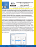
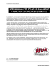
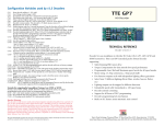
LokSound Users Manual V1.0 (english version) 1 Contents 2 1. Introduction ........................................................................................................ 3 2. Characteristics of the LokSound decoder ........................................................ 4 3. Connection of the decoder ................................................................................ 5 3.1. General tips for connection ............................................................................ 6 3.2. Pin allocation of the interface plug ................................................................ 6 3.3. Connection pattern generally. .......................................................................... 7 3.4. Connection at a direct current motor or a coreless motor ......................... 9 3.5. Connection to an alternating-current motor (field coil motor). .................. 9 3.6. Installation of the loudspeaker. ................................................................... 10 3.7. Connection of the lighting functions. .......................................................... 11 3.8. Connection of the auxiliary functions. ........................................................ 11 3.9. Connection of the wheel sensor. ................................................................ 11 4. Start-up .............................................................................................................. 12 4.1. Hardware test ................................................................................................. 12 4.2. Parameter adjustment ................................................................................... 12 4.2.1. Maerklin 6021 locomotive address adjustment ...................................... 13 4.2.2. Motor regulation: Yes or no ..................................................................... 14 4.2.2.1. Switch on load control ........................................................................... 14 4.2.2.2. Load control parameters ....................................................................... 14 4.2.3. Speed curve setup ...................................................................................... 15 4.2.4. Function outputs ........................................................................................ 16 4.2.4.1. Allocation of the outputs to the function keys ................................... 16 4.2.4.2. Example: Swiss light change ............................................................. 16 4.2.4.3. Bulb brightness adjustment .................................................................... 18 4.2.5. Sound adjustment ...................................................................................... 18 4.2.5.1. Diesel engine revolution / steam impact pitch adjustment ............... 18 4.2.5.2. Settings for diesel and electric locos ...................................................... 18 4.2.5.3. Particular settings for steam locos ......................................................... 19 4.2.5.3.1. Wheel sensor method .......................................................................... 19 4.2.5.3.2. Speed step dependent method ........................................................... 19 4.2.5.4. Volume adjustment ................................................................................. 20 4.2.5.5. Random sound effects ............................................................................ 20 5. Error tracing ...................................................................................................... 20 6. Appendix ............................................................................................................. 22 6.1. List of all supported CVs ............................................................................. 22 6.2 Technical data ................................................................................................... 33 6.3 Support and assistance .................................................................................... 34 Introduction Chapter 1 1. I NTRODUCTION Congratulations on your acquisition of a LokSound decoder! With LokSound your locomotives can finally sound like the real thing. You will soon notice that your LokSound equipped vehicles will become the center of attraction. Of course, you would like to install the module into your locomotive immediately, but first a request: Please read this guidance carefully before carrying out the installation!!! Although LokSound decoders are very durable, incorrect connection can destroy the module! ! Please also consider the following warnings: LokSound decoders are only for use in railway modeling. Avoid impact and pressure loads on the decoder. ! Electronic devices cannot withstand unusual humidity levels: the LokSound decoder may work incorrectly in too wet or too dry conditions . Always leave the heat shrink sleeve on the decoder. Please always disconnect the current supply from the decoder before you do any work with the decoder. Make sure during installation that neither the LokSound decoder itself nor any wire ends come into contact with the locomotive housing (there is a risk of short circuit). The free ends of unused wires must be insulated. Make sure during installation that no wires are squeezed or cut by the model's transmission parts. Treat the loudspeaker installation with extreme care: Do not apply pressure on the speaker and do not move the loudspeaker diaphragm! When soldering the speaker connections, do so briskly and only in the intended places! Pay close attention to the loudspeaker installation instructions given later in this manual! Adherence to these warnings will be rewarded by the long life and trouble-free operation of your LokSound decoder. 3 Chapter 2 Characteristics of the LokSound decoder 2. C HARACTERISTICS OF THE L OKS OUND DECODER LokSound is a universal electronics module for installation in model locomotives of gauges N, TT, H0 and 0. LokSound combines two components that so far have always had to be acquired separately: A full-feature digital decoder with outstanding characteristics: Multi-protocol operation: LokSound decoders understand both the common Märklin / Motorola format and the format of the NMRA/DCC system. Thus LokSound can be used with almost all presently available modern digital systems. LokSound was tested with, among others: Arnold Digital (DCC system) Lenz Digital Plus Märklin 6021 (New Motorola system) ROCO digital is cool Uhlenbrock Intellibox (DCC-Betrieb, new Motorola system) ZIMO MX-1 (DCC system) The change-over between protocols takes place fully automatically operation. during Universal motor connection: All types of motor can be attached to the LokSound module: direct current motors coreless motors (e.g. Faulhaber) alternating current motors (field coil motors). High motor pulse frequency: By using a pulse frequency of 22 kHz (!) the motor is very carefully operated. Thus the motor is not only quiet (no motor whine), but also heat generation is minimized and motor life is enhanced. Even coreless motors can be operated without problem by the LokSound decoder. Motor regulation: LokSound offers a (disconnectible) load control for direct current motors and coreless motors. Thus your locomotive will always keep the selected speed, no matter how large the train load is or whether it is traveling up or down gradients. Two function outputs AUX and REL: In addition to the two lighting outputs, two further function outputs are available for your choice of operation: You can switch on smoke generators or interior lighting or uncouple trains by pressing a key at your central processing unit! 4 Characteristics of the LokSound decoder Chapter 2 A digital, two-channel sound module with unique characteristics: Prototype recordings: Sounds of prototype locomotives were sampled using highquality microphones and recorded digitally onto a memory module. Thus your locomotives sound as accurate as the prototype! Two channels: In addition to the playing of steam impact or diesel sounds, a further sound can be generated at the same time. Steam whistles, bells, horns, etc. will sound just like the original. Steam, diesel and electric locomotive sounds are possible: LokSound can imitate every type of locomotive that it is possible to think of and whose sounds can be sampled! For each type of locomotive there is a prototypical operational sequence: Steam locomotive: Here there are two, three and four-cylinder steam locomotives, whose steam impacts increase in frequency as the speed of the model loco increases! Diesel locomotive: The engine can be turned off and restarted, both while stationary and while driving, with the engine sound naturally sensitive to the speed of the loco! Electric locomotive: Historical electric locomotives supply sound effects that are well worth listening to: from the motion of the pantograph to the clicking and cracking of the switchgear during acceleration! Sounds by key press: Pressing a function key (F1 to F8) emits the sounds! Random noises: Both while stationary and while moving, sounds such as air pump, water pump, coal shovels, compressed air discharging, etc. - at random intervals controlled by you. All sounds are alterable: All the sounds stored on the LokSound module can later be changed by you! As often as you wish! For this, you'll need a separate Windows PC and the ESU LokProgrammer set. 3. C ONNECTION OF THE DECODER Compared to conventional decoders, the LokSound module has additional connections, which are necessary for the sound functions. LokSound is delivered ex-factory with an NMRA/DCC conforming interface plug. The connection is particularly simple on locomotives with a matching socket. However, if an appropriate socket is not available on the locomotive, the plug must be removed and the wires soldered on by hand. 5 Chapter 3 3.1. G ENERAL TIPS Connection of the decoder FOR CONNECTION Always consider the following when digitizing a locomotive: Make sure that there are no direct connections between the motor and the model's current collectors; if there is, the decoder may be destroyed on first start-up. Isolate all connections and also beware of connections through the chassis/body; these are particularly common on Fleischmann locomotives. The LokSound decoder has fixed dimensions; make sure that the decoder receives sufficient area in the vehicle. When refitting the housing there must be no pressure on the decoder and no wires must be squeezed. Additionally, make certain that mobile parts such as transmissions and trucks are not obstructed by wires. Fasten the decoder in the locomotive durably with double-sided tape or hot glue, but never pack the decoder in foam material: The decoder gets very warm during operation and needs a good temperature heat sink. 100nF 4, 7n F Unused wires of the LokSound decoder must be isolated with tape and fixed in such a way that they cannot be disturbed during operation. Motor F ! 7n 1 4, FIG . Make sure the motor is sufficiently screened: A 10nF condenser in parallel with the motor connections is an absolute minimum; illustration 1 shows an optimally screened direct current motor. After installation and before start-up of the decoder, check all connections with an ohmmeter again; look in particular for short-circuits between the motor and the rail connections. 3.2. P IN ALLOCATION OF THE INTERFACE PLUG 6 The interface plug is wired in accordance with NMRA specifications, as in illustration 2. Pin 1 of the plug is marked by a small triangle. On suitably equipped locomotives, remove the blanking plug or shorting pins and carefully insert the plug of the LokSound decoder, without bending or tilting the pins of the plug. If, after installation, the lighting doesn't operate but otherwise the loco functions, then the plug is probably in the wrong way around. In such cases simply reinsert the plug the other way around. Connection of the decoder motor connection right 1 (orange) rear headlight 2 (yellow) not connected left rail (black)) 3 4 Chapter 3 8 right rail (red) 7 return line for lamps (V+) (blue) 6 front headlights (white) 5 motor connection left (gray) FIG . 2 3.3. C ONNECTION PATTERN GENERALLY Illustration 3 is a general diagram of connections to the LokSound decoder: The red wire is attached to the right rail (outer conductor). The black wire attaches to the left rail (neutral conductor). The orange wire is soldered to the right motor connection, the gray wire to the left motor connection. The rear headlights are soldered to the yellow wire, the front headlights to the white wire. The return line of the lamps is attached to the blue wire. The green wire belongs to the function output AUX, while the violet wire is meant for the REL port. The return line of the function outputs must be attached to any of the blue wires. To the two dark brown wires are attached to the loudspeaker. The two light brown wire can be attached a wheel sensor for the synchronization of steam impact sounds. The return line from the wheel sensor must also be attached to the blue wire. The REL port has an internal diode, so that a relay or other contact-switch device can be attached directly, without the need for additional components. 7 FIG . loudspeaker 8 3 wheel sensor light brown blue dark brown dark brown gray orange violet green white yellow blue black red headlights front rear DC-Motor rail connection right left function output AUX REL Chapter 3 Connection pattern generally L OK S OUND D ECODER Motor connection Chapter 3 3.4. C ONNECTION TO A DIRECT CURRENT MOTOR OR A CORELESS MOTOR The red wire is led to the right rail, the black wire to the left rail. The orange wire is led to the right motor connection, the gray wire to the left motor connection. Exchanging the two wires changes the driving direction. L OK S OUND D ECODER red rail connection right left FIG . 4 black orange right gray DC-Motor left 3.5. C ONNECTION MOTOR ). TO AN ALTERNATING - CURRENT MOTOR ( FIELD COIL The red wire is led to the right rail (or the pickup shoe with 3-rail systems), the black wire to the left rail (or the outer conductor with 3-rail systems). The orange wire is soldered to the left field coil, the gray wire to the right field coil. Exchanging the two wires changes the driving direction.The screening choke is retained, with one side connected to the motor. The other side is soldered to the blue wire of the decoder. L OK S OUND D ECODER red rail connection right left FIG . 5 black orange AC motor gray blue 9 Chapter 3 Installation of the speaker 3.6. I NSTALLATION OF THE LOUDSPEAKER . The LokSound decoders can be used only with the special loudspeaker offered by ESU: The use of other loudspeakers can at worst destroy the LokSound decoders; even if safe, the use of other loudspeakers will result in unsatisfactory sound. The correct installation position is crucial to the quality of the sound; a loudspeaker simply fastened somewhere without appropriate resonance space in the locomotive can never supply a good sound impression. Therefore be careful with the choice of the location and the requirement for resonance space. The loudspeaker must be arranged within the locomotive in such a way that the sound can emit unhindered from the locomotive. ! Please treat the loudspeaker with extreme caution: Put no pressure on it and don't operate the diaphragm by hand! The magnets of the loudspeaker are very strong! Keep all metallic articles away from the loudspeaker and, when soldering on the wires, secure the loudspeaker firmly, because the loudspeaker might be attracted to the soldering iron and could be destroyed. The loudspeaker is attached to the two dark-brown wires of the LokSound module. Make sure that you solder the wires briskly onto the marked places (on the small external printed circuit board) with a small soldering iron (max. 20 Watts). solder here! loudspeaker FIG . 6 sound cap 10 Optimal sound is reached by attachment of the small plastic sound cap supplied with every speaker: Install the speaker into the sound chamber and make sure that it is as sealed as possible: Use two-part adhesive to secure the loudspeaker tightly into the sound cap. The speaker wires should be fed through a small hole in the sound cap. Connection of the Lighting functions Chapter 3 3.7. C ONNECTION OF THE LIGHTING FUNCTIONS . Headlight connection is made as shown in fig. 3. The light outputs supply the full rail voltage. You therefore should use 19V bulbs in your locomotives. The brightness of the lights can be adjusted for a particular locomotive by the controlling software (CV60). See also chapter 4.2.4.3. 3.8. C ONNECTION OF THE AUXILIARY FUNCTIONS . The REL and AUX outputs of the LokSound decoders can be used for arbitrary purposes, e.g. switching of a smoke generator, switching of interior lighting, swiss light change, etc. The REL output already possesses an internal protection diode, so that without additional components a relay can be operated directly. 3.9. C ONNECTION OF THE WHEEL SENSOR . For the synchronization of steam impact sounds with wheel revolution, an external sensor can be used. The sensor input is the light brown wire on the LokSound decoder. Both reed contacts and mechanical signal initiators can be used. Any kind of potential-switching sensor can be used. blue L OK S OUND D ECODER If a reed switch is to be used, a miniature magnet (available from specialized traders) must be attached to a driving wheel axle in such a way that the magnet releases the reed contact with each wheel revolution. miniature magnet light brown driving wheel reed switch FIG . 7 Before the wheel sensor functions, various configuration variables must be set. See also chapter 4.2.5.3.1. 11 Chapter 4 Start-Up 4. S TART-UP ! After the installation of the LokSound decoder, it can be put into operation. Please examine again carefully with an ohmmeter all the wire connections: Are there short-circuits between one of the motor connections and the current supply? Were all connections between the motor connections and the chassis/ body really separated? Are the lamps correctly attached without contact to the chassis/body? Is the decoder installed in such a way that it cannot make any contact with the chassis/body? Does the LokSound decoder receive sufficient moving air for cooling? Can the LokSound decoder and/or its leads be pressed or squeezed when putting the body shell on? Is the loudspeaker attached so that the sound can emit unhindered from the locomotive? 4.1. H ARDWARE TEST After all the above points have been checked, current can be fed to the locomotive. We urgently recommend that the first tests of the re-equipped locomotive are carried out on a overcurrent-protected track section. Programming tracks of modern digital systems have this protection. Also, our auxiliary product LokProgrammer has extremely reliable overcurrent protection. You should try first to select a CV, e.g. CV1 (locomotive address). The standard locomotive address as supplied is address 3, which should be the address that is returned to your base equipment. If an error occurs here, please read Chapter 5 "Error tracing". When the CV readings function, you can begin test driving. By pressing the F2 key, the sound should be switched on, and either the diesel or steam impact sounds begin. Pressing F1 should cause a horn, whistle, bell, etc. to sound. 4.2. P ARAMETER ADJUSTMENT The LokSound decoder is compatible with the NMRA / DCC standard.Which CV is supported, and how the values affect the behavior, can be found in chapter 6.1 "List of all supported CVs". 12 All the CVs can be adjusted with any NMRA / DCC conformant system.LokSound was tested with the following systems: Lenz Digital plus, ZIMO MX1, Arnold Digital (DCC), and Uhlenbrock Intellibox. With all these systems (and theoretically also with all other standard-conformant systems), the CVs can be changed without problem. Start-Up Chapter 4 For details of how these functions are carried out in the respective systems, please see the manuals for those systems. The CVs can be adjusted with particular simplicity and convenience at a computer with the help of our LokProgrammer and its software. 4.2.1. M AERKLIN 6021 LOCOMOTIVE ADDRESS ADJUSTMENT The 6021 base station is able to send the new Motorola format. This is absolutely necessary for operation with LokSound , because only the new format supports the function keys F1 to F4. Unfortunately this format is not set up as standard on the 6021, which must first be adjusted. The first and second DIP switches, viewed from the outside at the back of the equipment, must be switched to the upper "on" position.A direction indicator beside the announcement of the locomotive address indicates this mode of operation. With the 6021, the LokSound CVs cannot at present be changed.Users of this controller are dependent for adjustment of the LokSound decoder on the LokProgrammer software or the specialist trade. However, the locomotive address can be changed as follows: 1. Place only the locomotive to be programmed on the track, select the old address of the locomotive and switch off the current with the "Stop" key. 2. Turn the travel control knob to the extreme left, exactly the same as if you wanted to change the driving direction. 3. Keep the knob pressed and switch on the current again with the "Go" key. The front display flashes: Programming mode. 4. Release the travel control knob. 5. Enter the new locomotive address at the keyboard. 6. Turn the travel control knob to the very left, as if you wanted to change the driving direction. 7. The locomotive reacts to the new address. 13 Chapter 4 4.2.2. MOTOR Start-Up REGULATION : Y ES OR NO The LokSound decoder has load control, which when used with direct current motors makes sure that the locomotive always drives with constant speed, independently of the actual load of the locomotive. The load control was optimized and tested with motors of ROCO, Bachmann (Liliput) and BRAWA, as well as with the new direct current motors of Maerklin. If you do not wish to use the load control, it can be deactivated completely. Please note that the load control is always switched off on use of an alternatingcurrent motor. Unfortunately, alternating current motors (series motors) are not suitable for load control. 4.2.2.1. S WITCH ON LOAD CONTROL If you would like to activate the load control, then bit 0 of CV49 must be set. First select the CV and note the value: if the value of CV49 bit 0 is 0 or 2, then the load control is deactivated. To activate load control, add a 1 to the current value and write this back to bit 0. Example: Current read value of CV49 bit 0: 02. To switch on the load control: write 03 in bit 0 of CV49. For a detailed description of all possible values for CV49, please see chapter 6.1. 4.2.2.2. LOAD CONTROL PARAMETERS The internally used PID algorithm of the load control depends on four parameters: CV56 contains the reference voltage, while configuration variables CV57 to CV59 contain the rule portions of the PID algorithm. Absolute reference: The voltage level is specified in CV56. E.g. If 20 V is desired, then the LokSound decoder always tries to supply a fraction of 20 V to the motor, independently of the external rail voltage. Relative reference: If CV56 contains a value of 0, the LokSound decoder automatically adjusts the reference voltage to the rail voltage. This method is the factory default of every LokSound decoder . 14 Start-Up Chapter 4 The rule portions of the PID algorithm (CV57 to CV59) are set at the factory to obtain satisfactory results with most common model train motors. These parameters should be changed only after consultation with ESU, because wrongly adjusted values can worsen the automatic controller action so much that the motor will no longer run. If different values are required, please contact ESU technical support (for addresses see chapter 6.3). 4.2.3. S PEED CURVE SETUP . The LokSound decoder has 256 internal speed settings. These can be set to suit the characteristics of the locomotive and assigned to the available speed steps (14, 28 or 128). There are two NMRA methods for doing this: Speed curve via CV2, CV5 and CV6: Give the starting voltage in CV2 and the maximum speed in CV5. CV6 corresponds to the speed at the mid drive position. This is how you define a change in the slope in the speed curve. This mode is active if CV29 bit 4 is set to zero! Freely defined speed curve: Arbitrary values for configuration variables CV67 to CV80 can be set. These 14 values are converted to the available speed steps. Thus the performance can be adapted optimally for the locomotive. This mode is active if CV29 bit 4 is set to 1! We recommend the use of the ESU LokProgrammer, with its software for the convenient computation and input of the data. 256 128 128 256 VHigh VMid 0 0 0 VStart 14 28 0 14 28 15 Chapter 4 4.2.4. FUNCTION Start-Up OUTPUTS The LokSound decoder has a total of four function outputs. Two of these are used for the lighting. The other two (AUX and REL) are available for independent use. Six further "functions" are available, which can produce various sounds at the push of a button. In addition, there are the functions "sound module on/off" and "acceleration on/ off". The latter function switches acceleration and brake rate off and is particularly useful for switchyard operation, where it is important that the locomotive follows commands as directly as possible. 4.2.4.1. ALLOCATION OF THE OUTPUTS TO THE FUNCTION KEYS ( FUNCTION MAPPING). The outputs can be assigned almost at will to the available function keys. Each function key is assigned a CV, to which an event can be assigned arbitrarily. Figure 8 shows the combination possibilities. A in the chart indicates the combination of function key, CV and event as set by the factory. This value which has to be stored in the particular CV is computed as follows: For each function exists a column and for each function key there you can see a line in Fig. 8. At the point where a certain line crosses the column of a desired function, you will find a value. This value has to be stored in the appropriate CV. Example: You want to assign the function output AUX to the key F4. To do so, you must write a 1 into the CV 38. The direction-dependent lighting can be controlled similarly. Each of the four available function outputs LICHTV, LICHTH, AUX and REL can be set to operate differently according to the direction of travel. For further information regarding the NMRA function mapping, see their web pages at http://www.nmra.org 4.2.4.2. EXAMPLE : S WISS LIGHT CHANGE The function mappings make many options possible. A good example of this is the Swiss light change: For this a third lamp circuit is required, and this is to be switched on when the headlights are switched on, but independently of the driving direction. 16 F0 Function key F8 F7 F6 F5 F4 F3 F2 F1 F0 #35 #36 #37 #38 #39 #40 fixed fixed Function F2 Function F3 Function F4 Function F5 Function F6 Function F7 Function F8 1 1 2 2 2 • 2 1 1 • Function F1 Description #33 CV #34 Output Forward Headlight Forward Headlight Output Reverse Headlight Reverse Headlight 4 1 1 1 1 4 4 2 2 2 2 8 8 8 8 Output AUX Output REL 4 Acceleration On / Off 4 4 4 4 • 16 16 8 8 8 8 32 • Sound module On / Off 32 16 16 16 16 64 • Soundslot 1 64 128 Soundslot 2 32 32 32 32 • 128 64 64 64 • Soundslot 3 64 128 Soundslot 4 128 • 128 128 Soundslot 5 • Soundslot 6 • Function Mapping according to NMRA Chapter 4 A BB . 17 8 Chapter 4 Start-Up Illustration 3 shows a possible wiring of this arrangement, whereby the AUX output is used for the third lamp circuit. The decoder must now be told that this third lamp circuit is to be switched on whenever the lighting key is pressed. The variable CV33 is given the value 05 and the variable CV34 is given the value 06. 4.2.4.3. B ULB BRIGHTNESS ADJUSTMENT LokSound enables the brightness of the bulbs to be dimmed in 32 steps, so that the brightness can be set to suit the model. In addition the lamps are pulsed, i.e. switched on and off very quickly. The desired value must be registered in variable CV60. A value of 1 means minimum brightness, a value of 31 means maximum brightness. The value 0 means direct connection of the lamps. 4.2.5. S OUND ADJUSTMENT LokSound offers many possibilities for adjusting the sound. All the sound parameters are registered in CVs, which can be manipulated exactly like all other configuration variables. 4.2.5.1. DIESEL ENGINE REVOLUTION / STEAM IMPACT PITCH ADJUSTMENT Diesel engine revolution can be adjusted using two CVs: In CV50 the number of revolutions of the diesel engine while stationary is registered. The default value of 128 represents the original speed. A value of 64 means half speed. In CV51 the number of revolutions of the diesel engine at full speed is registered (full power). A value of 255 means double the original speed. The same parameters are responsible in steam locos for the pitch of the steam impacts: The steam impacts not only follow each other with increasing speed but also vary in pitch. 4.2.5.2. SETTINGS FOR DIESEL AND ELECTRIC LOCOS If a diesel locomotive is to be simulated, then both CV52 and CV53 must be set to 0. 18 Start-Up Chapter 4 4.2.5.3. PARTICULAR SETTINGS FOR STEAM LOCOS For the simulation of a steam locomotive, the steam impact sounds must be synchronized with wheel revolution. LokSound offers two ways to achieve this: either in accordance with an external wheel sensor, or dependent on the speed steps. Depending on which method is to be used, some CVs need to be set accordingly. As set by the factory, LokSound uses the speed step dependent method. 4.2.5.3.1. W HEEL SENSOR METHOD The wheel sensor must be attached as described in Chapter 3.9. Thereafter, set both CV52 and CV53 to 255. 4.2.5.3.2. S PEED STEP DEPENDENT METHOD For the speed step dependent method, the spacing of the steam impact sounds is adjusted using the variables CV52 and CV53. This method is recommended if an external wheel sensor cannot be used. The adjustment of the variables to match the wheel movement may require several attempts, but perseverance will achieve satisfactory results. Such results can however be achieved only if the load control is activated. For locomotives fitted with the Märklin universal motor (for which load control must be switched off) only the use of an external wheel sensor will produce satisfactory results. For the adjustment of the CVs, proceed as follows: Set CV52 to 100 and CV53 to 50. Sit the locomotive on the track and drive it (with the sound switched on) in speed step 1. Activate, if available, the 128 speed step mode! Measure the time in seconds that the driving wheel takes at this speed to complete a revolution. Divide the time by 0.02304. Enter the value (to the nearest whole number) in CV52. Halve the value that you entered in CV52 and enter it into CV53. Increase the speed step (e.g. to 10) and determine whether the steam impact rhythm matches the wheel revolution. If the steam impacts come too quickly, increase the value in CV53 gradually. If the steam impacts come too slowly, decrease the value of CV53. 19 Chapter 4 Start-Up 4.2.5.4. V OLUME ADJUSTMENT The volume of the LokSound decoder can be adjusted in four steps. Step 0 is the quietest setting, step 3 the loudest. Please note that different maximum volumes apply to the different loudspeaker sizes. These must not be exceeded, otherwise the loudspeaker will be damaged!! ! Enter the desired value into CV61 ! . size of speaker max.sound level Ø 15 mm 2 Ø 20 mm 2 Ø 23 mm 2 Ø 28 mm 3 Ø 40 mm 3 4.2.5.5. R ANDOM SOUND EFFECTS The frequency of the random sounds that are played during steam locomotive operation can be set by the two variables CV54 and CV55. CV54 contains the minimum spacing between two random sounds, while CV55 contains the maximum spacing between two random sounds. Both values thus form an interval, within which LokSound randomly selects and plays sounds. The units used for both CVs are 0.184 seconds. Example: For a minimum interval in CV54 of 1.5 seconds, enter 1.5 / 0.184 (= 8) into CV54. 5. E RROR TRACING If, after installation, the LokSound decoder does not function as desired, there can be many causes. Often, no hardware defect is present, but various settings of the decoder are incorrect. The following are some example symptoms and their solutions: 20 Error Tracing Chapter 5 As soon as the locomotive is set on the track, the command station shows: "Overcurrent". Here a short-circuit of the supply current is obviously present. Possibly there are still direct connections to the chassis/body. As soon as a CV is read / written, the command station shows: "Overcurrent". This is probably a short-circuit of the motor connections. Please check that all direct connections between the chassis/body and the motor have been removed. The locomotive moves forward and backwards normally, but the lighting does not function. At the factory, the LokSound decoder is set to 14 speed steps. Newer DCC systems however use 28 /128 speed steps. Either change the command station over to 14 speed steps, or program the LokSound decoder for 28 / 128 speed steps (see CV29 in chapter 6.1). The lighting/sound functions and CVs can be read/written, but the locomotive does not start. Check the following points: A short-circuit at the engine and/or a too high power input can bring the overcurrent protection of the LokSound decoder into operation. If the load control is deactivated: The starting voltage (CV2) may be too small. When using older motors, the motor pulse frequency should be reduced from 22kHz to 87Hz (see CV9). A locomotive with a Maerklin AC motor drives only at half throttle. The power input of this motor is briefly so high that the over-current protection operates. Solder two chokes each of at least 4.7 uH across both inputs to the field coils. With load control activated, the locomotive drives very unevenly at low speed steps. Examine whether the phenomenon disappears after deactivating the load control (see chapter 4.2.2.1). If so, then the control parameters do not suit the motor being used. Please contact ESU technical support. The decoder drives perfectly, but no sound is heard. Examine whether the wiring to the loudspeaker is correct. If using the Maerklin 6021, make sure that the new Motorola format is used (see chapter 4.2.1.). If this is all OK, then most likely the loudspeaker is defective. Please note our FAQ (frequently asked questions) list on our webpage at www.loksound.de for further information about error tracing. ! 21 Chapter 6 List of all supported CVs 6. A PPENDIX 6.1. L IST OF ALL SUPPORTED CV S CV 1 Locomotive address (Primary Address) [NMRA] Description: Normal address of the loco decoder. Range of values: 0 - 127 Default value : 3 Access: read/write Remarks: The value 0 switches the receiver off for NMRA Operation-Mode-Packets. Service-Mode-Packets are however still accepted. For the normal address to be accepted, bit CV29.5 must additionally be set to 0. CV2 Start voltage (VStart) [NMRA] Description: Motor voltage for the lowest speed step (speed step 1). Range of values: 0 - 255 Default value : 7 Access: read/write Remarks: Effective only if bit CV29.4 is set to 0. (Speed characteristic VStart, VMid, VEnd.) CV3 : Acceleration Rate [NMRA] Description: This value multiplied by 0.869 results in the time in seconds from stationary to maximum speed. Range of values: 0 - 64 Default value : 0 Access: read/write Remarks: The value 0 means that the internal acceleration delay is not active, i.e. the speed set for the motor becomes effective immediately. 22 List of all supported CVs CV4 Chapter 6 Deceleration Rate [NMRA] Description: This value multiplied by 0.869 results in the time in seconds from maximum speed to stationary. Range of values: 0-64. Default value: 0. Access: read/write. Remarks: The value 0 means that the internal acceleration delay is not active, i.e. the speed set for the motor becomes effective immediately. CV5 Maximum speed (VEnd) [NMRA] Description: Motor voltage for the highest speed step (speed step 14/28/128). Range of values: 0-255. Default value: 1. Access: read/write. Remarks: Effective only if bit CV29.4 is set to 0. (Speed characteristic VStart, VMid, VEnd.) The values 0 and 1 mean: the maximum value (255) is used. CV6 Mid speed (VMid) [NMRA] Description: Motor voltage for the middle speed step (speed step 7/14/64). Range of values: 0-255. Default value: 1. Access: read/write. Remarks: Effective only if bit CV29.4 is set to 0. (Speed characteristic VStart, VMid, VEnd.) CV7: Manufacturer Version Number Description: Access: [NMRA] Version number of the loco decoder. read only . 23 Chapter 6 CV8 Description: Access: CV9 List of all supported CVs Manufacturer ID [NMRA] Registered ID of the loco decoder manufacturer. For ESU the code is 151. read only . Motor control period (Total PWM Period) [NMRA] Description: Period duration of the PWM signal for the control of the motor. Range of values: 0, 204. Default value: 0. Access: read/write. Remarks: Value 0: 90 µs (corresponds to 22.2 kHz pulse frequency). Value 204: 11.5ms (corresponds to 87 Hz pulse frequency). CV17+18 : Extended Address [NMRA] Description: Long address of the loco decoder. Range of values: 128-10239. Default value: 0. Access: read/write. Remarks: CV17 contains the extended address high byte (CV17.7 and CV17.6 must always be set). CV18 contains the extended address low byte. Only applies if CV29.5 is set to 1. CV19: Consist Address Description: [NMRA] Additional address of the loco decoder for driving in Multi Unit Consists (Multi Traction). Bit 7 indicates the relative driving direction: 0 = normal direction, 1 = reverse direction. Range of values: 0-127. Default value: 0. Access: read/write. Remarks: The value 0 means: Consist address not active. 24 List of all supported CVs Chapter 6 CV29 Configuration Data 1 Description: [NMRA] Bit 0: Direction behavior. 0 = normal, 1 = inverted. The functions FL and FR change accordingly. Bit 1: Speed step system [for headlight behavior]. 0 = 14 speed steps, 1 = 28/128 speed steps. Bit 4: Selection of the motor characteristics [speed curve]. 0 = determined by CV2, CV5, CV6. 1 = determined by CV67-V80. Bit 5: Selection of the loco address. 0 = normal. 1 = two byte extended address. All other bits have no meaning. Default value: Access: 0 read/write. CV33 Function assignment (Output Location FL(f )) Description: [NMRA] Allocation of operations to the built-in function(F) while in forward drive. Bit 0: Bit 1: Bit 2: Bit 3: Front light. Rear light. Auxiliary function AUX. Auxiliary function REL. All other bits have no meaning. Access: Remarks: Default value: 1 read/write. The functions activated here are dimmed in accordance with CV60. 25 Chapter 6 List of all supported CVs CV34 Function assignment FL(r) Description: Default value: Remarks: (Output Location FL(r)) [NMRA] Allocation of operations to the built-in function (F) while in reverse drive. Bit 0: Front light. Bit 1: Rear light. Bit 2: Auxiliary function AUX. Bit 3: Auxiliary function REL. 2 The functions activated here are dimmed in accordance with CV60. CV35 Function assignment F1 (Output Location F1) Description: Allocation of operations to Function 1 (F1). Default value: Bit 0: Front light. Bit 1: Rear light. Bit 2: Auxiliary function AUX. Bit 3: Auxiliary function REL. Bit 4: Acceleration/braking rate deactivated. Bit 5: Drive sound. Bit 6: Sound[slot] 1. Bit 7: Sound[slot] 2. 4 CV36: Function assignment F2 Description: (Output Location F2) Allocation of operations to Function 1 Bit 0: Front light. Bit 1: Rear light. Bit 2: Auxiliary function AUX. Bit 3: Auxiliary function REL. Bit 4: Acceleration/braking rate deactivated. Bit 5: Drive sound. Bit 6: Sound 1. Bit 7: Sound 2. Default value: 26 8 [NMRA] [NMRA] List of all supported CVs CV37 Function assignment F3 Chapter 6 (Output Location F3) Description: Allocation of operations to Function 3 (F3). Default value: Bit 0: Auxiliary function AUX. Bit 1: Auxiliary function REL. Bit 2: Acceleration/braking rate deactivated. Bit 3: Drive sound. Bit 4: Sound[slot] 1. Bit 5: Sound[slot] 2. Bit 6: Sound[slot] 3. Bit 7: Sound[slot] 4. 4 CV38 Function assignment F4 Description: (Output Location F4) [NMRA] [NMRA] Allocation of operations to Function 4 (F4). Bit 0: Auxiliary function AUX. Bit 1: Auxiliary function REL. Bit 2: Acceleration/braking rate deactivated. Bit 3: Drive sound. Bit 4: Sound 1. Bit 5: Sound 2. Bit 6: Sound 3. Bit 7: Sound 4. Default value: 8 CV39: Function assignment F5 (Output Location F5) Description: Allocation of operations to Function 5 (F5). Default value: Bit 0: Auxiliary function AUX. Bit 1: Auxiliary function REL. Bit 2: Acceleration/braking rate deactivated. Bit 3: Drive sound. Bit 4: Sound 1. Bit 5: Sound 2. Bit 6: Sound 3. Bit 7: Sound 4. 16 [NMRA] 27 Chapter 6 List of all supported CVs CV40 Function assignment F6 (Output Location F6) Description: Allocation of operations to Function 6 (F6). Default value: Bit 0: Auxiliary function AUX. Bit 1: Auxiliary function REL. Bit 2: Acceleration/braking rate deactivated. Bit 3: Drive sound. Bit 4: Sound 1. Bit 5: Sound 2. Bit 6: Sound 3. Bit 7: Sound 4. 32 CV49 Extended Configuration Description: Default value: Access: Remarks: [ESU] Bit 0: 0 = control inactive. 1 = control active. Bit 1: 0 = REL output 0 Hz (always on). 1 = REL output 87 Hz (pulsed). 0. read/write. Using bit 1 the AUX output can be switched to a pulsed operation at 87 Hz, 50% OD. This is useful for digital couplers. CV50 Sound Speed Min Description: [NMRA] [ESU] Sets the drive sound speed at speed step 1. The value is divided by 128 to give a sound speed factor. Range of values: 0-255. Default value: 128 (corresponding to a factor of 1, i.e. original speed). Access: read/write. 28 List of all supported CVs CV51 Sound Speed Max Chapter 6 [ESU] Description: Sets the drive sound speed at the highest speed step. The value is divided by 128 to give a sound speed factor. Range of values: 0-255. Default value: 192. Access: read/write. CV52 Steam impact (Sound Steam Min) [ESU] Description: Multiplied by 0.02304, the value is the time in seconds between two steam impacts for speed step 1. Range of values: 0-255. Default value: ?? Access: read/write. Remarks: If both CV52 and CV53 are set to 0, then the special run mode for steam sound is deactivated. This setting is necessary for diesel and electric locomotive sound. If both CV52 and CV53 are set to 255, then the distance between two steam impacts is determined by the external wheel sensor (wheel impulse). CV53 Steam impact (Sound Steam Max) [ESU] Description: Multiplied by 0.02304, the value is the time in seconds between two steam impacts for speed step 2. Range of values: 0-255. Default value: read/write. Remarks: See also CV52. With CV53 the upward gradient of the sound adjustment is matched to the transmission of the loco. See chapter 4.2.5.3.2. 29 Chapter 6 List of all supported CVs CV54 Random sound (Sound Random Min) [ESU] Description: Multiplied by 184.32, the value is the time in milliseconds for the lower limit of the random interval. The value is used to determine the intervals between random sounds. Range of values: 0-255. Default value: 20. Access: read/write. Remarks: If both CV54 and CV55 are set to 0, then playing of random sounds is deactivated. CV55 Random sound (Sound Random Max) [ESU] Description: Multiplied by 184.32, the value is the time in milliseconds for the upper limit of the random interval. The value is used to determine the intervals between random sounds. Range of values: 0-255. Default value: 40. Access: read/write. Remarks: If both CV54 and CV55 are set to 0, then playing of random sounds is deactivated. CV56 Regulation Reference Description: [ESU] Absolute EMK voltage in tenth volts, supplied to the motor at maximum speed (absolute reference). If the value is set to 0, the Regulation Reference is automatically adjusted to the current rail voltage (relative reference). Range of values: 0-255. Default value: 0. Access: read/write. 30 List of all supported CVs CV57: Regulation Parameter Q0 Chapter 6 [ESU] Description: Parameter q0 for the PID rule algorithm. Range of values: 0-255. Default value: 100. Remarks: Please do not change this value yourself - contact Support. CV58 Regulation Parameter Q1 [ESU] Description: Parameter q0 for the PID rule algorithm. Range of values: 0-255. Default value: 141. Remarks: Please do not change this value yourself - contact Support. CV59 Regulation Parameter Q2 [ESU] Description: Parameter q0 for the PID rule algorithm. Range of values: 0-255. Default value: 52. Remarks: Please do not change this value yourself - contact Support. CV60 Dimmer (Function Dimmer) [ESU] Description: This value divided by 32 is used to set the dimming characteristics for the functions specified in CV33 and CV34. The value 0 deactivates the function dimmer, i.e. the outputs are either constantly on or are switched off. Range of values: 0-31. Default value: 0. CV61 Speaker [ESU] Description: Specifies the loudspeaker volume from 0 (quiet) to 3 (loud). (Adjust for the appropriate loudspeaker size.) Range of values: 0-3. Default value: 0. 31 Chapter 6 List of all supported CVs CV64 Märklin Address Description: Address Value Address Value Address Value Address Value 1 2 3 4 5 6 7 8 9 10 11 12 13 14 15 16 17 18 19 20 21 22 23 24 25 26 27 28 29 30 31 32 33 34 35 36 37 38 39 40 41 42 43 44 45 46 47 48 49 50 51 52 53 54 55 56 57 58 59 60 61 62 63 64 65 66 67 68 69 70 71 72 73 74 75 76 77 78 79 80 3 1 12 15 13 4 7 5 48 51 49 60 63 61 52 55 53 16 19 17 Default value: Access: Remarks: 32 [ESU] Defines the Maerklin address of the loco decoder. The address is interpreted according to the Motorola format. The following table shows the values that must be written in CV64 in order to receive the appropriate Maerklin address. 28 31 29 20 23 21 192 195 193 204 207 205 196 199 197 240 243 241 252 255 253 244 247 245 208 211 209 220 223 221 212 215 213 64 67 65 76 79 77 68 71 69 112 115 113 124 127 125 116 119 117 80 83 81 92 95 93 84 87 85 12. read/write. The value 85 (Maerklin Idle Address) deactivates the receiver for Maerklin packages. List of all supported CVs Chapter 6 CV67-80 : Speed characteristic (Speed Table) [NMRA] Description: A motor voltage is assigned to the 14 speed steps. The intermediate values for 28/128 speed steps are interpolated. Range of values: 0-255. Default value: 0. Access: read/write. Remarks: The values in the table must be evenly spaced. 6.2 TECHNICAL DATA Dimensions: Structure: Operation Voltage: Supported Protocol: decoder section: Sound section: Loudspeaker: 43 x 16 x 8 mm Mulitlayer PCB, double-sided SMT technology 5 to 21 V DCC / NMRA-Standard (Base-Line and Extended Packet Format) Märklin / Motorola (old and new) 14, 28 and 128 speed steps 9999 addresses 0.9 A maximum load 0.6 A maximum load on the function outputs Connection of DC and AC motors possible (autodetect). 22kHz pulse frequency - ideal for coreless motors. Load control (disconnectible). Over-current protection of the motor output. Two channels. Integrated bridge output stage, approx. 0.5 Watts. Sound data in flash memory alterable. Special loudspeaker in five different sizes (15mm, 20mm, 23mm, 28mm, 40mm). 33 Chapter 6 6.3 Support and Assistance S UPPORT AND ASSISTANCE If you require more information, please contact in the first instance the dealer from whom you purchased your LokSound decoder. Your dealer is competent to answer all questions concerning model railways. You may also have a look at the support section of our website for further assistance. However, if your dealer is not able to solve your problem, you can turn to ESU's technical support service. You can reach us by telephone: ++49 7043 - 90 75 27 Every Tuesday from 10:00am to 12:00am Every Wednesday from 06:00pm to 08:00pm ! 34 by Fax : ++49 7043 - 90 75 36 by email: [email protected] by post: ESU electronic solutions ulm GmbH - technical support Am Tiefen See 5 D-75433 Maulbronn Germany please visit our webpage at http://www.loksound.de