1
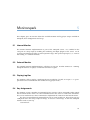
Edited by:
Joschka Boedecker
Klaus Dorer
Markus Rollmann
Yuan Xu
Feng Xue
June 2008
Version 1.1
Contents
1
2
Introduction
1
1.1
1.2
1.3
1.4
1
1
2
2
System Overview
2.1
2.2
2.3
2.4
2.5
3
What is SimSpark?
History of the Project
About this Manual
Reader’s Guide to the Manual
The Server
The Monitor and Logplayer
The Sample Client
Available Simulations
Available Robot Models
Getting Started
3.1 Download and Installation Instructions
3.2 An Example of a Simulation Run
4
Simspark
4.1 Perceptors
4.1.1 General message format
4.1.2 General Perceptors
4.1.3 Soccer Perceptors
4.2 Effectors/Actuators
4.2.1 General Effectors
4.2.2 Soccer Effectors
4.2.3 Older Version Effectors
4.3 Simulation Update Loop
4.3.1 Single-threaded Timer
4.3.2 Multi-threaded Timer
4.4 Setup Scripts
5
Monitorspark
5.1
5.2
5.3
5.4
Internal Monitor
External Monitor
Playing Log files
Key Assignments
3
3
4
4
4
4
5
5
7
13
13
13
13
15
18
18
19
20
21
22
23
23
25
25
25
25
25
i
6
Agentspark
6.1 Behaviors
6.1.1 SoccerbotBehavior
6.2 How to change Behaviors?
7
Simulations
7.1 The Soccer Simulation
7.1.1 Overview
7.1.2 Environment and Objects on the Field
7.1.3 Rules Judged by the Automatic Referee
7.1.4 Rules Judged by the Human Referee
7.1.5 Setup Script
8
The Robot Models
8.1 Soccerbot
8.2 Nao
8.2.1 Parameters
8.2.2 Implementation
9
Further Resources
9.1
9.2
9.3
9.4
9.5
9.6
A
License
Project Homepage
Mailing Lists
IRC channel
Wiki
Thesis and Papers
How to contribute?
27
27
27
27
29
29
29
29
31
31
32
33
33
36
36
39
41
41
41
41
41
41
42
43
ii
Introduction
1.1
1
What is SimSpark?
SimSpark is a multi-agent simulation system for agents in three-dimensional environments. Its
goal is to provide a high degree of flexibility for creating new types of simulations. It builds on
a flexible application framework and exhausts the idea of replaceable components throughout
its implementation.
In comparison to specialized simulators, users can create new simulations by using a scene
description language. SimSpark is a powerful tool to state different multi-agent research questions and is used as the official simulator for the RoboCup Simulation League competition.
1.2
History of the Project
SimSpark was developed as part of the RoboCup initiative, initially called Robot World Cup
Initiative. It is an international research and education initiative. It is an attempt to foster AI
and intelligent robotics research by providing a standard problem where wide range of technologies can be integrated and examined, as well as being used for integrated project-oriented
education.
For this purpose, RoboCup chose to use soccer game as a primary domain, and organizes
competitive RoboCups. The simulation league is one of several leagues where the entire soccer game takes places in a simulated environment. SimSpark’s two dimensional predecessor
simulation models the players and the ball as flat spheres. It further lacks a realistic physical
environment.
As one of the long term goals of the soccer simulation is to aim for realism the long term
objective are realistic humanoid players in a physical environment. These players should one
day challenge the champion of the most recent World Cup.
Therefore, on the RoboCup 2003 Symposium a new approach to a three-dimensional physically realistic soccer simulation was proposed [KO04]. In a road map discussion for the Soccer
Simulation League on RoboCup 2003, the participants decided on adding the three-dimensional
simulation to the competitions.
For RoboCup 2004, SimSpark was successfully used for the first official competition in
RoboCup Simulation League 3D. The soccer simulation for this tournament was developed in
parallel with the SimSpark simulator. In its initial version players were modeled as spheres in
a physical three dimensional world. Since then SimSpark grew considerably and now supports
humanoid players with articulated bodies.
It served from the beginning as a test bed and a guide for essential new features that were
added to the simulator during development. However changes to the simulator core were never
1
customized for the soccer simulation. Instead generic simulator services were implemented
with all soccer specific details contained in a set of plugins (see [OR05]).
1.3
About this Manual
This manual describes the SimSpark simulator. Like the simulator itself it is subject to constant
change in an ongoing development effort. It assumes that you are familiar with the basic
concepts of multi agent simulations.
It aims to be a guide on how to develop your own RoboCup agents, construct new robot
models, build your own custom monitor or use the trainer command protocol to test your
agents.
If there are errors, inconsistencies, or oddities, please send a message to the SimSpark
developer mailing list 1 (please see chapter 9 for details) with the location of the error and a
suggestion of how it should be corrected. We are always looking for anyone who has an idea
on how to improve the manual, as well as proofread or rewrite a section of the manual.
The latest manual can be downloaded at the SimSpark project homepage 2 .
1.4
Reader’s Guide to the Manual
This section gives a rough overview about the contents of this manual.
In chapter 2 we give a short overview introduction and to the system and its defining
components. This overview is given both from a component view that distinguishes the server,
the monitor the logplayer etc. and from a software architecture point of view. In the latter we
describe the different software modules, their purpose and responsibility.
In chapter 3 you will find instructions howto build SimSpark from source and how to install
it into your system. Further an illustrated example run of a simulation is given as a first guide
to get the you started.
The following chapter 4 is a reference gives you detailed information about the messages
that are sent from the server to the agent and vice versa. These messages contain information
about agent percepts and agent command strings.
In chapter 5 we give an overview about the available monitor and log player setups. Their
configuration and usage is described in detail there.
The following chapter 6 explains the agentspark demo agent. This agent is a reference
implementation and a basis to start your own agent implementation work. We explain how to
configure the agent to use custom behavior implementations.
In chapter 7 we introduce simulations that are currently available for SimSpark. In particular the soccer simulation is described in detail here.
The robot models, and in particular our Soccerbot is described in chapter 8.
In the resources chapter 9 we point you to further papers and thesis works related to
SimSpark. In addition mailing lists, web sites and IRC channels are given that allow you to
participate in the project and to reach the SimSpark developers.
1 [email protected]
2 http://simspark.sourceforge.net/
2
System Overview
2
SimSpark is built upon an application framework called zeitgeist. This framework provides
basic OS abstractions like file and archive support, logging, shared libraries etc.), a scripting
interface to Ruby and a powerful plugin mechanism coupled with an object hierary that provides
a unified namespace. This library is the backbone of the system.
Zeitgeist allows us to load new classes at runtime from plugins and install object instances
in a hierarchy. We can locate these instances via path expression just like files in a file system. At various well known locations are objects called servers that provide services to other
parts of the system. The script server that provides an interface to the Ruby ist installed at
/sys/server/script.
Built as part of this object hierarchy is a scene graph that the system uses to represent
the simulated world. This scene graph and related concepts are managed within the next
layer of the system, that we call oxygen. It provides classes that encapsulate concepts like
transformations, basic geometric primitives, physical bodies and collision primitives. It further
provides access to a rigid body physical simulation.
The oxygen library further implements basic simulation services like agent management
and a monitor framework. It is responsible to keep track and to update connected agents and
monitor processes. Last but not least it provides a customizable run loop service. This service
is implemented as an abstract run loop that is extended with plugins as needed. In parts of the
system can be replaced or left out easily as for example rendering or monitor support.
The Visualization of the scene and input event processing services are provided by the
kerosin library. It implements the infrastructure for rendering and device management. Concrete implementations are again provided by plugins. This allows the simulation to use different
back ends or graphic engine. A default set of plugins utilizes plain OpenGL and the SDL library.
2.1
The Server
The SimSpark server hosts the simulation process that manages the simulation. It is responsible
to advance the simulation, i.e. modify the simulation state in a continuous run loop.
Objects in the scene change their state, i.e. one ore more of their properties like position,
speed or angular velocity changes due to several influences. They are under the control of a
rigid body physical simulation, that resolves collisions, applies drag, gravity etc. Agents that
take part in the simulation also modify objects with the help of their effectors.
Another responsibility of the server is to keep track of connected agent processes. Each
simulation cycle the server collects and reports sensor information for each of the sensors of all
connected agents. It further carries out received action sequences that an agent triggers using
its available effectors.
3
Depending on the setup of the server it renders the simulation itself, i.e. it implements an
internal monitor that omits the network overhead or it manages and updates remote monitor
processes. In the latter configuration the rendering of the scene is deferred to remote processes.
2.2
The Monitor and Logplayer
The SimSpark monitor is responsible to render the current simulation. It connects to a runing
server instance from which it continuously receives a stream of update data that describes the
simulation states either in full or as incremental updates relative to the preceding state.
The format of the data stream that the server sends to the monitor is called monitor
format. It is a customizable language used to describe the simulation state.
Apart from describing the pure simulation state each monitor format may provide a mechanism to transfer additional game specific state. For the soccer simulation this means for example
current play mode and goals scored so far.
The monitor client itself only renders the pure scene and defers the rendering of the game
state to plugins. These plugins are intended to parse the game state and display it as an overlay,
e.g. print out playmode and scores on screen.
The monitor can further be configured to read a protocol of scene updates from a file and
act as a logplayer. In this mode it does not connect to a server instance but replays an recorded
game. The format of the logfile is identical to the monitor protocol used on the network.
2.3
The Sample Client
SimSpark provides a simple agent implementation that demonstrate how to interact with the
server. It demonstrates how to connect to the server, how to read perceptor values and how to
use effectors. The demo behaviour of the agent is implemented as a plugin that can be replaced
in order to customize it for different simulations. 1
2.4
Available Simulations
SimSpark currently provides two version of robotic soccer. There is a sphere based older version
that is available up to version rcssserver3d-0.5.2. In this soccer version the agents on the
soccer field were simple rolling spheres.
This soccer simulation was the first step away from its two dimensional predecessor simulation into a three dimensional world. Since then SimSpark progressed to a more realistic
form of the soccer game. In recent versions players possess articulated bodies that resemble
humanoid robots.
2.5
Available Robot Models
1 A repository of agent implementations from previous Robocups is available at http://www.uni-koblenz.de/
~murray/robocup/rc07/Binaries/binaries_3D.html
4
Getting Started
3.1
3
Download and Installation Instructions
This chapter explains how to install SimSpark on an Ubuntu Linux system1 . It should work with
slight modifications on other distributions like Fedora, Suse and especially Debian.
1. Enable additional repositories
Depending on the distribution version you are using you might need to enable additional
repositories in order to install all required packages. Please refer to your system specific
documentation for details. In Ubuntu Linux these repositories are called Universe and
Multiverse
To enable them you have to edit the /etc/apt/sources.list file and update the local
package database.
$ sudo gedit /etc/apt/sources.list
$ sudo apt-get update
In RPM based distributions you may need to enable further download locations or download and install RPM packets manually. There are specialized search engines for RPM
packages available like
(a) http://packman.links2linux.de/ and
(b) http://rpmfind.net/
2. Install dependencies
SimSpark builds and depends upon the work of other software projects. We use the Gnu
autotools to configure and build SimSpark. Therefore these packages are required:
(a) autoconf
(b) automake
(c) libtool
Further required packages are:
(a) Ruby
(b) The Open Dynamics Engine (ODE)
(c) The boost C++ libraries
1 This guide is adapted from the guide created by the Little Green Bats Team at http://www.littlegreenbats.nl/
?q=node/70
5
(d) S-Lang (libslang)
The rendering of SimSpark can be omitted from the build process therefore these packages are optional:
(a) OpenGL
(b) FreeGlut
(c) SDL
(d) Freetype
(e) Developer Image Library (DevIL)
(f) Tiff library (libtiff)
In order to build the SimSpark documentation you need a Latex installation (e.g. tetex).
If you want to build the rsgedit gui you need to install wxWidgets. The following commands download and installed the required packages:
$ sudo apt-get install g++ ruby1.9 ruby1.9-dev libode0-dev libboost-dev libsdl-dev
libfreetype6-dev libdevil-dev autoconf automake1.9 libtool freeglut3-dev tetex-extra
cvs xlibs-dev libtiff4-dev libslang1-dev
$ sudo rm /usr/bin/ruby
$ sudo ln -s /usr/bin/ruby1.9 /usr/bin/ruby
$ sudo ln -s /usr/lib/libruby1.9.so /usr/lib/libruby.so
3. Check out the source from the source forge CVS repository
The SimSpark source is hosted in a CVS repository at sourceforge.net. In order to build the
source first download the current version, this is called check out in CVS terminology:
$ cvs -d:pserver:[email protected]:/cvsroot/sserver login
When you get asked for a password, just press enter.
$ cvs -z3 -d:pserver:[email protected]:/cvsroot/sserver
co -P rcsoccersim/rcssserver3D
4. Build and install the soccer server
The automake build tools use a configure script that adapts the build process to your
system allows you to customize it. The configure script accepts a number of options that
you can add to it’s command line:
(a) --help lists all available configure options. There are some more available that
would exceed the scope of this manual
(b) --enable-debug=no builds an optimized version of SimSpark that contains no debug
symbols
(c) --enable-kerosin=no builds SimSpark without rendering support
(d) --prefix=/some/path defines the path where the make install will later install the
SimSpark executable, plugins and resources into your system. If omitted it defaults
to /usr/local
Change in to the top level source directory call the bootstrap script that invokes the autotools, run configure with your custom options, start the build process and install the
server into your system.
$ cd rcsoccersim/rcssserver3D/
$ ./bootstrap
6
$ ./configure
$ make
$ sudo make install
5. Make sure the linker can find your shared libraries if you changed the install prefix as
described above with the --prefix option.
$ sudo gedit /etc/ld.so.conf
Add your install prefix if it isn’t already there, save and close.
$ sudo ldconfig
6. run the simulation
$ cd
$ simspark
3.2
An Example of a Simulation Run
This chapter gives shows how to start a simulation and connect an agent. The soccer simulation
is used to illustrate this. We assume that you have already compiled and installed the simulator
successfully as described in chapter 3.1.
To follow the example run given here it is best to work with several console windows where
you start and control the server monitor and agent separately.
• Start the Server
The first step is to start the simulation server. To do this type simspark on the console.
The server is by default configured to run without internal monitor support and to start
the soccer simulation.
You should now see several diagnostic messages fly by, starting with the following greeting:
simspark, a monolithic simulator 0.1
Copyright (C) 2004 Markus Rollmann,
Universitt Koblenz.
Copyright (C) 2004, The RoboCup Soccer Server Maintenance Group.
Type ’--help’ for further information
The output ends with the confirmation that the server now listens on the default port
3100 for agents and 3200 for external monitors.
(NetControl) ’AgentControl’ setting up a server on TCP:3100
(NetControl) ’MonitorControl’ setting up a server on TCP:3200
(SimulationServer) entering runloop
(SimulationServer) running in single thread
We are now ready to connect a monitor to the simulator.
7
• Start the Monitor
The monitor is a separate application that connects to the server and displays the simulated scene. To start the default monitor type monitorspark. By default the monitor is
configured to connect to a simulation on the local machine. You can however run the
server and monitor on different machines.
When the monitor starts up you should again see some diagnostic messages fly by. The
output ends with the confirmation that the monitor tries to connect to the server. If
successful it will then open a separate window and display the simulated scene, please
see figure 3.1.
(SimulationServer) init
(NetClient) ’SparkMonitorClient’connecting to TCP 127.0.0.1:3200
(NetClient::SendMessage) ERROR: send returned error ’Broken pipe’
(SimulationServer) entering runloop
(SimulationServer) running in single thread
After the monitor started you are able to use the mouse and keyboard to navigate the
scene. Please refer to chapter 5 for a complete list of the available key bindings.
You can use the numbers of the keypad to navigate to different positions on the playing
field. The view after pressing 3 is given in figure 3.2. The movement of the camera is
controlled with the arrow keys, PgUp and PgDown. Press the left mouse button and move
the mouse to change the camera view.
Figure 3.1: View of the soccer simulation after the simulator has just been started.
• Connect an agent
The next step is to connect one or more agents to the simulation. To do this please change
to a separate console window and type agentspark. This starts the example agent that is
included with SimSpark.
8
Figure 3.2: Change the view by pressing ’3’ on the keyboard.
You should now see a humanoid robot appear on the field, as in figure 3.3. This default
agent does nothing useful but waving his arms.
• Start the simulation
The next step is to start the soccer game. To do this please change back to the monitor
window and press ’k’. The simulation time now start running and the game state changes
to BeforeKickOff, please compare to figure 3.5.
9
Figure 3.3: An agent connected to the server.
Figure 3.4: Moving around on the field using the arrow keys, PgUp, PgDown, and the mouse (with left mouse
button pressed).
10
Figure 3.5: Press ’k’ to start the game. The play mode will switch to ’KickOff’ and the time will advance.
11
12
Simspark
4
In this section you find information about the messages that are sent from the server to the
agent (perceptors) and vice versa (effectors). A description of the perceptors and effectors can
also be found in [Sch08] (German), [Lea07] (Slovak), and to some part in [Vor06] (concerns
the older ”spheres” simulation though, so some information is outdated).
4.1
Perceptors
Perceptors are used to sense the environment of the agent. They are sent from the server to each
agent and contain agent specific and perceptor specific information about the environment and
the agent itself. There are perceptors that are available to all kinds of simulations and soccer
specific perceptors.
4.1.1
General message format
Messages from and to the server use S-expressions (short for symbolic expressions) as their
basic data structure. The basic idea of S-expressions is very simple: they are either strings, or
lists of simpler S-expressions. They are probably best known for their use in the Lisp family of
programming languages where they are used for both code and data.
An advantage of using S-expressions over other data formats is that it provides an easy to
parse and compact syntax that is to some extent still readable by humans for debug purposes.
It is further easy to add new sensors to the messages as the parser on the client side can easily
ignore unknown parts.
Messages exchanged between client and server use the default ASCII character set, i.e.
one character is encoded in a single byte. Further each individual message is prefixed with the
length of the payload message. The length prefix is a 32 bit unsigned integer in network order,
i.e. big endian notation with the most significant bits transferred first.
4.1.2
General Perceptors
The perceptors described in this subsection are available to all types of simulation. In other
words they are not specific to the soccer environment.
13
GyroRate Perceptor
The gyro rate perceptor delivers information about the orientation of a body. Currently only the
upper torso contains a gyro perceptor. The message contains the GYR identifier, the name of
the body to which the gyro perceptor belongs and three rotation angles. These angles describe
the orientation of the body with respect to the global coordinate system.
Message format: (GYR (n <name>) (rt <x> <y> <z>))
Example message: (GYR (n torso) (rt 0.01 0.07 0.46))
HingeJoint Perceptor
A hinge joint perceptor receives information about the angle of the correponding single axis
hinge joint. It contains the identifier HJ, the name of the perceptor (see table 8.1) and the
position angle of the axis. Zero degrees corresponds to straightly allinged bodies. A hinge joint
is displayed in figure 4.1.
Figure 4.1: Hinge Joint ( [Smi06])
Message format: (HJ (n <name>) (ax <ax>))
Example message: (HJ (n laj3) (ax -1.02))
UniversalJoint Perceptor
A universal joint perceptor receives information about the two angles of the correponding two
axis universal joint. It contains the identifier UJ, the name of the perceptor (see table 8.1) and
the position angles of the two axis. Zero degrees corresponds to straightly allinged bodies. A
universal joint is displayed in figure 4.2.
Message format: (UJ (n <name>) (ax1 <ax1>) (ax2 <ax2>))
Example message: (UJ (n laj1 2) (ax1 -1.32) (ax2 2.00))
14
Figure 4.2: Universal Joint ( [Smi06])
Touch Perceptor
This perceptor works like a bumper that is triggered if the agent part to which it is mounted
collides with another simulation object. The perceptor always reports its own unique name.
This allows the use of more than one touchperceptor per agent. Further the value 0 meaning
no collision detected or 1 meaning collision detected is given.
Message format: (TCH n <name> val 0|1)
Example message: (TCH n bumper val 1)
ForceResistance Perceptor
This perceptor informs about the force that acts on a body. Currently, it is available for the
left and the right foot (lf, rf). After FRP and the name of the body it contains two vectors that
indicate the point on the body to which the force applies and the force vector itself.
Message format: (FRP (n <name>) (c <px> <py> <pz>) (f <fx> <fy> <fz>))
Example message: (FRP (n lf) (c -0.14 0.08 -0.05) (f 1.12 -0.26 13.07))
4.1.3 Soccer Perceptors
The following perceptors are soccer specific and only available in the soccer simulation.
Vision Perceptor
Your robots possess a special omnicam with some smart image processing software attached :).
If using the regular visionperceptor, Robots have a 360 degrees view. With the RestrictedVisionPerceptor (which became the default in version 0.5), the view field of the robot is restricted to
90 degrees (this is of course configurable in rcssserver3D.rb). The direction of the view (pan
and tilt) can be changed with the pantilt effector. The camera can pan to any angle (the initial 0 degrees pan direction is the direction towards the opponent side), and tilt around the
horizontal plane.
15
The VisionPerceptor delivers lists of seen objects, where objects are either others robots,
the ball, or markers on the field. Currently there are 8 markers on the field: one at each corner
point of the field and one at each goal post.
With each sensed object you get (see figure 4.3):
• The distance between the player and the object.
• The angle in the horizontal plane. Zero degree always points to the opponent goal.
• The latitudal angle. Here zero degree means horizontal.
Figure 4.3: Polar coordinates as supplied by the 3D Soccer Server [Vor06]
Contrary to 2D soccer simulation, the vision system does not deliver object velocities. Objects can be occluded by other objects (this is not completely implemented yet). All distances
and angles are given relative to the camera position. The camera is currently located at the
center of the robot’s torso.
The noise parameters of the vision system are as follows:
• A small calibration error is added to the camera position. For each axis, the error is
uniformly distributed between -0.005 m and 0.005 m. The error is calculated once and
remains constant during the complete match.
• Dynamic noise normally distributed around 0.0 + distance error: sigma = 0.0965 +
angle error (x-y plane): sigma = 0.1225 + angle error (latitudal): sigma = 0.1480
A vision message is started with See followed by the visible objects. Possible objects are:
Flags: The marker flags on the field corners F1L, F1R, F2L, F2R
Goalposts: The goal posts of both goals G1L, G1R, G2L, G2R. Goals and flags are located as shown
in 7.2.
Ball: The ball B
Players: Players P with additional information (team <teamname>) (id <playerID>)
Message format: (See (<name> (pol <distance> <angle1> <angle2>)) (P (team <teamname>) (id <playerID>)
(pol <distance> <angle1> <angle2>)))
Example message: (See (F1L (pol 19.11 111.69 -9.57)) (F2L (pol 16.41 -115.88 -11.15)) (F1R (pol
46.53 22.04 -3.92)) (F2R (pol 45.49 -18.74 -4.00)) (G1L (pol 9.88 139.29 -21.07))
(G2L (pol 8.40 -156.91 -25.00)) (G1R (pol 43.56 7.84 -4.68)) (G2R (pol 43.25
-4.10 -4.71)) (B (pol 18.34 4.66 -9.90)) (P (team RoboLog) (id 1) (pol 37.50
16.15 -0.00)))
16
GameState Perceptor
The GameStatePerceptor contains information of the current play time which starts from zero
at kickoff of either half. It also contains the current game status. The first percept you get from
this perceptor additionally tells you about some of the game variables, like ball weight and field
size.
All other percepts start with GS and contain the current simulation time as a float value
passed in seconds and the playmode. Possible playmodes are ”BeforeKickOff”, ”KickOff Left”,
”KickOff Right”, ”PlayOn”, ”KickIn Left”, ”KickIn Right”, ”corner kick left”, ”corner kick right”,
”goal kick left”, ”goal kick right”, ”offside left”, ”offside right”, ”GameOver”, ”Goal Left”, ”Goal Right”,
”free kick left”, ”free kick right”, ”unknown”. For an up to date list of all playmodes refer to
(./plugin/soccer/soccertypes.h)
Message format: (GS (t <time>) (pm <playmode>))
Example message: (GS (t 0.00) (pm BeforeKickOff))
AgentState Perceptor
The AgentState perceptor gives information about the internal state of the agent. It reports
information about the current battery status and the temperature of the agent.
Message format: (AgentState (temp <degree>) (battery <percentile>))
Example message: (AgentState (temp 48) (battery 75))
Hear Perceptor
Agent processes are not allowed to communicate with each other directly, but agents may
exchange messages via the simulation server. For this purpose agents are equipped with the socalled hear perceptor, which serves as an aural sensor and receives messages shouted by other
players. Actually the underlying model stems from the 2D Soccer Simulation and has been
integrated in the 3D simulator since server version 0.4. Percepts have the following format:
Message format: (hear <time> ’self’|<direction> <message>)
Example message: (hear 12.3 self ‘‘helloworld’’)
The value of time is a real number and reflects the time when the given message was heard.
Source is either the relative direction in degrees where the sound was located, or self if the
player has a statement by his own. M essage may consist of characters from the ASCII printing character subset [0x20, 0x7E], among which the alphanumerical symbols and mathematical
operators can be found for example. Three characters from this range are, however, excluded:
the white space character (!) and the normal brackets ( and ).
The hear perceptor comes up with some restrictions:
1. Messages are restricted to a maximal length (currently 8 bytes).
2. Messages shouted from beyond a maximal distance (currently 50.0 meters) cannot be
heard.
17
3. The number of messages which can be heard at the same time is bounded: Each player
has the maximal capacity of one heard message by a specific team every two sensor cycles (thus every 0.4 seconds per team). There are separately tracked capacities for both
teams, because teams should not be able to block the hear perceptors of their opponents
by shouting permanently. If more messages from players of one team arrive, they are
processed in the order of arrival; the remaining messages are simply not heard.
Messages shouted by oneself, though, can always be noticed [Vor06].
4.2
Effectors/Actuators
Effectors are used to act within the simulation. They are sent to the server to change the game
state accordingly. There are effectors that are available to all kinds of simulations and soccer
specific effectors.
4.2.1
General Effectors
The effectors described in this subsection are available to all types of simulation. In other words
they are not specific to the soccer environment.
Create Effector
When an agent initially connects to the server it is invisible and cannot take affect a simulation
in any meaningful way. It only possesses a so called CreateEffector.
An agent uses this effector to advice the server to construct it according to a scene description file it passes as a parameter. This file is used to construct the physical representation and
all further effectors and preceptors.
Message format: (scene <filename>)
Example message: (scene rsg/agent/soccerbot056.rsg)
After the agent representation is constructed in the server the agent should do further
simulation specific setup. For example in the soccer simulation each agent is required to register
to a team and acquire a unique player number. For these tasks usually a special effector like the
SoccerInitEffector is used.
HingeJoint Effector
Effector for all axis with a single degree of freedom. The first parameter is the name of the axis.
Table ??? shows a list of all available hinge joints. The second parameter contains the change
in angle of the joint.
Message format: (<name> <ax>)
Example message: (lae3 5.3)
18
UniversalJoint Effector
Effector for all axis with a two degrees of freedom. The first parameter is the name of the axis.
Table ??? shows a list of all available hinge joints The second and third parameter contain the
change in angle of the two joints. The order of the joints is the same as in the name.
Message format: (<name> <ax1> <ax2>)
Example message: (lae1 2 -2.3 1.2)
4.2.2 Soccer Effectors
The following effectors are soccer specific and only available in the soccer simulation.
Init Effector
The init command is sent once for each agent after the create effector sent the scene command.
It registers this agent as a member of the passed team with the passed number. All players
of one team have to use the same teamname and different numbers. If an agent sends 0 as
playernumber, the number is assigned automatically by the server to the next free number. The
maximum amount of teams is two, the maximal amount of players is currently four. The side
on which a team starts to play depends on which team connected first.
Message format: (init (unum <playernumber>)(teamname <yourteamname>))
Example message: (init (unum 1)(teamname FHO))
Beam Effector
The beam effector allows a player to position itself on the field before the game starts. The
x and y coordinates define the position on the field with respect to the coordinate system of
figure ???. The rot value allows to define the rotation angle of the player. Zero degrees points
to positive x axis, 90 degrees to positive y axis.
Message format: (beam <x> <y> <rot>)
Example message: (beam 10.0 -10.0 0.0)
Say Effector
The say effector permits communication among agents by broadcasting messages. In order to
say something, the following command has to be employed:
Message format: (say <message>)
Example message: (say ‘‘helloworld’’)
M essage may consist of 8 characters, which may be taken from the ASCII printing character
subset [0x20, 0x7E] except the white space character (!) and the normal brackets ( and ). For
details and restrictions please see Section 4.1.3, about the hear perceptor, the dual sensor to
this actuator.
19
4.2.3 Older Version Effectors
The effectors in this subsection have been available in older versions of the simulation and are
now no longer available
Drive Effector
To use the omnidrive of the agent, you have to use the so called ”DriveEffector”, which takes a
cartesian vector (x y z) with a maximum length of 100 units. The x-coordinate points towards
the opponents team side of the field, z points up. With the DriveEffector, you set a kind of motor
force, i.e. if you want to drive full speed for a while, it is sufficient to use the DriveEffector
*once*. The force you set is applied at each simulator step until you change it again. The
DriveEffector works reliable, there is a small error for forces along each axis (each up to 2% of
the applied force). The error is normally distributed around 0.0.
Using the omnidrive consumes battery. You get to know of battery states by reading the
AgentStatePerceptor. If the battery is empty, the omnidrive will stop working. It is also possible
to push away other robots. Using this feature to push away opponents is discouraged :).
Message format: (drive <x> <y> <z>)
Example message: (drive 20.0 50.0 0.0)
Kick Effector
To move the ball, you have the option of simply using the robots to push the ball into a desired
direction, or you can use the kickeffector to kick the ball. Originally, we did not intend to create
an artificial kickeffector. However, to make use of the 3rd dimension, this was the easiest way.
It is intended to remove this kind of kick effector in future versions (not this years’ competition)
in favor of a real physical device.
The kickeffector can accelerate the ball radially away from the robot body. The kickeffector
takes an angle as first argument. This is the latitudal angle (in degrees) for accelerating the ball.
It is restricted to a number between 0 and 50. The second argument indicates the kicking power
and this is a number between 0 and 100. It is interpreted as the percentile of the maximum
available power. The kickeffector adds a force and a torque to the ball. This happens over
a fixed number of simulation steps. Currently 10 cycles are used. This corresponds to 1/10s
simulation time. To kick the ball, the ball has to be very close to the robot, i.e. it has to be
within the so called kickable margin of the player. Currently 0.04m are configured.
You cannot change the kicking angle in the horizontal plane. This means that you have to
move the robot so that it can kick into the desired direction. Right now, the kickeffector is not
very strong, because something like an offside rule is missing. It should also not be possible to
move other robots by kicking the ball against them anymore. (at least not very much :) Like
the DriveEffector, the kickeffector does only work if the robot touches the soccer field.
The kickeffector noise has the following parameters:
• The angle error in the x-y plane is quite low and normally distributed around 0.0 with
sigma = 0.02.
• The latitudal angle error is normally distributed around 0.0. This angle error is low with
sigma = 0.9 at both extreme positions, i.e. 0 and at 50 degrees. Towards the middle of
the range the angle error gets higher with sigma up to 4.5.
• The kick power error is normally distributed around 0.0 with sigma = 0.4
20
Message format: (kick <angle> <power>)
Example message: (kick 20.0 80.0)
Catch Effector
The goalie (agent number 1) is the only player with the ability to catch a ball. The goalie can
catch the ball in play mode ’playe on’, if the ball is inside the penalty area and close to the
robot, i.e. it has to be within the so called catch margin of the player. The current value of
catch margin is 2 meters.
The catcheffector puts the ball in front of the goalie on the ground and moves players away
that are closer than 2 meters to the goalie by 5 meters.
Message format: (catch)
Example message: (catch)
4.3
Simulation Update Loop
SimSpark implements a simple internal event model that immediately executes every action
received from an agent. It does not try to compensate any network latency or compensate for
different computing resources available to the connected agents.
A consequence is that SimSpark currently does not guarantee that events are reproducible.
This means repeated simulations may have a different outcome, depending on network delays
or load variations on the machines hosting the agents and the server.
A benefit of the simple structure however are speed gains that make it interesting for machine learning tasks as in these setups an often large number of different agent and simulation
configurations are repeatedly tested.
Further the SimSpark main loop is highly customizable as it is entirely build upon plugins
we call simcontrol nodes. Simcontrol nodes are registered to the simulation server. They act in
response to control events. The simulation server repeatedly generates these as it executes an
abstracted the main loop.
The event types are an ’init’ event once when the simulation server starts and a ’done’ event
on shutdown. The main then loop cycles repeatedly through the ’start cycle’, ’sense agent’, ’act
agent’ and ’end cycle’ events.
Apart from generating control events the simulation server advances the simulation time
passed in the last cycle. Depending on its configuration it either does this in discrete time
quanta or in one single step.
A simcontrol node further can take responsibility for the time measurement, for example
to synchronize the simulation time with the real time used to render the scene. Otherwise the
simulation is stepped a fixed time step as often as possible.
In this way all management tasks are implemented as plugins to the simulation server. This
involves the agent management, monitor management, rendering, mouse and keyboard input
and network code.
This setup allows us to configure the simulation at runtime as either a monolithic application that does both simulation and rendering or as a dedicated simulation server that defers
rendering to a remote monitor application.
21
4.3.1 Single-threaded Timer
In the singled-threaded mode, the main loop cycles repeatedly through the ‘start cycle’, ‘sense
agent’, ‘act agent’ and ‘end cycle’ events( see Figure 4.4). There are two noticeable details:
• Each cycle duration is 20ms, if the simulation is fast than real time, it will wait; otherwise,
if the simulation is very slow, it will run many physics updates once without interaction
with agents. If the simulation is very slow, it will give up to catch up the real time and
print warning. So you may have problem while the computer is not fast enough.
• The ‘act agent’ event is followed after ‘sense agent’, the action which the agent send
according to nth cycle will be realized in the (n + 1)th cycle, i.e. the action has been
delayed one cycle. See for Figure 4.5 explanation.
Figure 4.4: Single-threaded loop UML sequence diagram
22
Figure 4.5: Synchronization between SimSpark and agent
4.3.2
Multi-threaded Timer
In modern time, computers have more than one CPU or dual cores in one CPU. This improve the performance greatly, but only the multi-threaded program can benefit. SimSpark
has an experimental multi-threaded running loop, it can be switched on simply by change the
simulationServer.setMultiThreads(false) to simulationServer.setMultiThreads(true)
in the spark.rb file.
The implementation of multi-threaded loop is based on two conditions. First, every SimControlNode response for different parts of the simulation, they perform one by one in the
singled-threaded mode, but they can run in parallel. Second, there is a active scene which
stores the whole simulation data in a tree. The physics engine and SimControlNode interact
through the active scene. As we know, the physics computation is the most time-consuming,
and the physics engine does not need to access the active scene during physics computation.
So the physics computation and SimControlNodes can run in parallel. At last, we get the multithreaded simulation loop as Figure 4.6. Note that the agent’s action are also delayed one cycle
in the multi-threaded loop.
4.4 Setup Scripts
TODO:
• describe purpose of scripts in /̃.rcssserver3d/
• kerosin.rb for rendering configuration of simspark
23
Figure 4.6: Multi-threaded loop UML sequence diagram, note that each SimControlNode runs in separated
thread.
24
Monitorspark
5
This chapter gives an overview about the available monitor and log player setups available in
SimSpark, their configuration and usage.
5.1
Internal Monitor
The internal monitor implementation is part of the SimSpark server. It is enabled in the
simspark.rb setup script by enabling the rendering and input plugins of the server. To do
so please uncomment the lines sparkSetupRendering() and sparkSetupInput(), i.e. remove
the leading ’#’ comment markers.
5.2 External Monitor
The external monitor implementation is called monitorspark. It either connects to a running
SimSpark instance or replays a simulation run from a log file.
5.3 Playing Log files
The monitor is able to replay a simulation that is recorded in a log file. It accepts a --logfile
parameter on its command line that enables the log player mode.
5.4 Key Assignments
The monitor accepts a number of commands by key or mouse. These commands either control
the movement of the camera or send commands back to the server to control the simulation.
The soccer simulation uses these commands to implement the controls for the human referee.
The list of accepted default command short cuts is given in table 5.4. These short cuts are
configured in the two setup scripts bindings.rb and soccerbindings.rb that the SimSpark
monitor reads on start up.
”user-manual”
25
Table 5.1: Key assignments for monitorspark
key
q
left mouse button
right mouse button
keypad plus
pageup
pagedown
keypad minus
a
left arrow
d
right arrow
w
up arrow
s
down arrow
1
2
3
4
5
6
7
l
r
k
b
m
n
x
p
f
b
l
function
quit monitor
mouse look
move camera up
move camera up
move camera up
move camera down
move camera down
move camera left
move camera left
move camera right
move camera right
move camera forward
move camera forward
move camera backward
move camera backward
camera to left goal
camera to left corner
camera to middle left
camera to middle right
camera to middle
camera to right corner
camera to right goal
free kick left
free kick right
kick off
drop ball
move agent
shoot ball
move ball
pause the playback of a log file
move forward in the log file
move backwards in the log file
playback the log file
26
Agentspark
6
This chapter introduces AgentSpark, the demo agent implementation available for SimSpark.
6.1
Behaviors
AgentSpark is a demo agent implementation for use with the SimSpark server. It serves as
a testbed for agent implementation. It implements all low level details of connecting and
communicating with the server. It further implements an abstract run loop. The behavior of
this agent skeleton is implemented using plugins. On of these plugins is configured and installed
at run time.
6.1.1
SoccerbotBehavior
The SoccerbotBehavior is a minimal example of an agent that acts on a soccer field and
controls our current humanoid soccer bot model. It demonstrates reading preceptor values and
controlling the robot with the installed effectors in a control loop. The implemented behavior
resembles the classic hello world program in a way. It moves up the arms of the robot and
repeatedly waves hello.
6.2
How to change Behaviors?
The different Behaviors of AgentSpark are encapsulated in classes that derive from the Behavior
class. Classes of this type implement an interface with two functions that each return a command string that is then send to the SimSpark server.
The first implemented function is Init. This function is called once when the agent initially
connected to the server. It is typically used to construct the agent representation in the server
with the help of the scene effector and to move the agent to a suitable start position in the
simulation.
The second implemented function is called Think. This function is called every simulation
cycle. As a parameter it receives the sensor data as reported from the server in the last cycle.
This function should implements the main behavior run loop of each agent.
27
28
Simulations
7
This chapter is about the different simulations available with SimSpark. In particular the soccer
simulation is described in detail.
7.1
7.1.1
The Soccer Simulation
Overview
We implemented a simulation for SimSpark where two teams of up to 5 humanoid robots play
soccer against each other. This seemingly simple setup poses a challenge to agent implementers
on several levels.
In order to act in a meaningful way on the playing field the first challenge is to localize
your agent on the playing field. To support this the agents perceive their relative position to a
set of landmarks, called flags on the playing field. These flags mark corner and goal spots of
the playing field. Further the relative location of other players and the ball are perceived.
If an agent knows where it is and where it wants to be in the near future the next challenge
is to walk there. The structure of the humanoids are sufficiently realistic to make this non trivial.
Further the agent has to recover and get up if fallen over.
Another challenge is kicking the ball. As trivial this sounds to a human it is far from trivial
for a robot to keep its dynamic balance when kicking and controlling the direction of the ball.
Agents that are able to move and kick the ball need to cooperate and form a team. Only
the effective application of strategic and cooperative behaviors forms a successful team.
Most rules of the soccer game are judged by an automatic rule set that enforces the basic
soccer rule set. However more involved situations like detection unfair behavior still require a
human referee.
This soccer simulation is also used as the official competition environment for the 3D Soccer Simulation League at RoboCup1 [KAK+ 97] [KA00] [BMO+ 05] [MBdSG+ 07]. The robots
used in the simulation at the competitions is the Soccerbot as described in chapter 8.
7.1.2
Environment and Objects on the Field
The dimensions of the soccer field are 50 by 32 meters. The center spot has a radius of 4.5
meters. Each goal is 9 by 2 meter with a height of 4 meters. The soccer field is surrounded by
1 For
more information on RoboCup, see also http://www.robocup.org/
29
Figure 7.1: A screen shot of the soccer simulation with 5 vs 5 robots
30
a border of 10 meters in each direction. Space outside this border area is not reachable by an
agent. The soccer ball has a radius of 0.4 meter and a mass of 430 gram.
At each corner of the soccer field, and at the goal posts, a distinctive flag is placed. The
positions of these flags are fixed and known to each agent. Agents perceive the relative position
of a subset of these flags and are therefore able to localize themselves on the soccer field. The
corner flags are color coded in the visualization. Agents distinguish flags through their code
name as shown in figure 7.2.
50m
F1L
G1L
F1R
G1R
4.5m
32m
G2L
F2L
9m
G2R
F2R
Figure 7.2: The dimensions of the soccer pitch and the object markers on the field as perceived by an agent
7.1.3 Rules Judged by the Automatic Referee
The automatic referee automatically limits the time of each game half. It further keeps track
which player was the last one to touch the ball and checks whether the ball enters the goal
penalty areas of the soccer field.
It detects and scores goals, it automatically judges ball out and gives a kick in or corner
kick in to the correct team. The offside rule is implemented but still experimental.
7.1.4
Rules Judged by the Human Referee
The human referee acts through a connected monitor. It is responsible to give the kick off
command to start each game half. The automatic referee currently does not resolve situations
where the game got stuck if for example several player block each other and no one is able to
reach the ball. Further it does not detect fouls like the use of hands or otherwise behavior on
the soccer field.
31
In these cases the human referee can drop ball the ball, i.e. put it on a random location
on the playing field to unstuck the game. He is further able to command a free kick where
one player is able to shoot from a short distance to the goal.
7.1.5
Setup Script
32
The Robot Models
8
Below, we only describe the most advanced robot model that comes with the simulation package
at this point in time: the Soccerbot. There are some other models which you can find in the
directory app/simspark/rsg/agent/, e.g., the soccerplayer.rsg, or the hoap2.rsg files. These
are currently not in use in any simulation, and considered experimental.
Besides that, work is in progress on other robot models and will be described here when
usable. We plan to integrate an improved model of the HOAP-2 robot from Fujitsu Automation,
and models of the VisiON 4g robot, and the Sony AIBO. For help on how to model new robots
for your simulation, please have a look at tutorials in the SimSpark Wiki at
http://simspark.sourceforge.net/wiki/.
8.1
Soccerbot
This is the robot currently used in the competitions of the 3D Soccer Simulation League at
RoboCup. It is a humanoid robot with 20 degrees of freedom (DOF) as depicted in figure 8.3.
Its current dimensions are quite unrealistic for a real humanoid robot (see table 8.1 which is
due to instabilities in the physics simulation at the time the robot was first modeled. This is a
serious shortcoming of this robot model and should be changed. Another open issue is that the
joint ranges are not limited in the current model. This allows for very unrealistic movements
which can be fun to watch, but can lead to unfair behavior in a competition.
The Soccerbot has several kinds of sensors available. It uses a (omni-directional) vision
sensor (see section 4.1.3) to get information about objects in its environment1 . In order to
detect the contact with the ground and the resulting force at the feet, it is equipped with a
Force Resistance Perceptor (see section 4.1.2) in each foot. It can sense the current simulation
time with a GameState Perceptor (see section 4.1.3) and the change in orientation of its torso
with a GyroRate Perceptor (see section 4.1.2). Furthermore, it has proprioceptive sensors that
allow to sense the angle of each joint (see sections 4.1.2 and 4.1.2 for HingeJoint Perceptor and
UniversalJoint Perceptor descriptions, respectively). An overview over the joint perceptors and
effectors is given in table 8.1.
In figure 8.4 shows an example message which the agent receives from the server in a
single simulation cycle including sense information from all the perceptors of the agent.
1 It
is currently located in the center of the torso, which should be changed to be in the head.
33
Figure 8.1: Frontal view of the Soccerbot in the simulation
Figure 8.2: Side view of the Soccerbot in the simulation
hhead
RA1
warm
RA2
RA3
LA1
RA4
LA2 lshoulder
LA3
htorso
wleg
LA4
RL1
lupperarm
LL1
RL2
llowerarm
LL2
RL3
lhip
LL3
lthigh
RL4
LL4
lshank
RL5
LL5
RL6
wf oot
LL6
lf oot
Figure 8.3: Overview of the degrees of freedom of the Soccerbot
34
Name
head
torso
left shoulder
right shoulder
left upper arm
right upper arm
left lower arm
left lower arm
left hip
right hip
left thigh
right thigh
left shank
right shank
left foot
right foot
Width
Depth
Height
0.39m (radius)
1.37m
0.96m
1.41m
0.445m 1.017m 0.536m
0.445m 1.017m 0.536m
0.445m 0.398m 0.506m
0.445m 0.398m 0.506m
0.445m 0.316m
0.6m
0.445m 0.316m
0.6m
0.273m 0.273m
0.2m
0.273m 0.273m
0.2m
0.56m
0.56m
1.3m
0.56m
0.56m
1.3m
0.56m
0.56m 0.964m
0.56m
0.56m 0.964m
0.6m
0.956m 0.095m
0.6m
0.956m 0.095m
Mass
0.3kg
1.8kg
0.5kg
0.5kg
0.2kg
0.2kg
0.2kg
0.2kg
0.1kg
0.1kg
0.25kg
0.25kg
0.25kg
0.25kg
0.1kg
0.1kg
Table 8.1: Physical properties of the Soccerbot.
Table 8.2: Perceptor and effector names
Connection between
Shoulder - body
Upper arm - shoulder
Forearm - upper arm
Hip - body
Upper leg - hip
Lower leg - upper leg
foot - lower leg
Joint type
Universal joint
Hinge joint
Hinge joint
Hinge joint
Universal joint
Hinge joint
Universal joint
Perceptor name
laj1 2 raj1 2
laj3 raj3
laj4 raj4
llj1 rlj1
llj2 3 rlj2 3
llj4 rlj4
llj5 6 rlj5 6
Effector name
lae1 2 rae1 2
lae3 rae3
lae4 rae4
lle1 rle1
lle2 3 rle2 3
lle4 rle4
lle5 6 rle5 6
35
(time (now 19.60))(GYR (n torso) (rt -0.02 -0.01 -0.00))(See (F1L (pol 10.34
45.02 -16.70)) (F2L (pol 68.43 174.14 -2.56)) (F1R (pol 103.28 -86.10 -1.66))
(F2R (pol 123.46 -123.42 -1.43)) (G1L (pol 27.94 165.40 -6.96)) (G2L (pol
35.03 168.43 -5.56)) (G1R (pol 106.49 -104.59 -1.83)) (G2R (pol 108.57 -108.33
-1.80)) (B (pol 56.95 -122.42 -3.02)) (P (team RoboLog) (id 2) (pol 10.50
-179.98 -0.07)))(UJ (n laj1 2) (ax1 0.00) (ax2 90.63))(UJ (n raj1 2) (ax1
-0.00) (ax2 90.63))(HJ (n laj3) (ax 90.77))(HJ (n raj3) (ax -90.77))(HJ (n
laj4) (ax 87.96))(HJ (n raj4) (ax 88.40))(HJ (n llj1) (ax 0.03))(HJ (n rlj1)
(ax -0.02))(UJ (n llj2 3) (ax1 -0.03) (ax2 0.02))(UJ (n rlj2 3) (ax1 -0.02)
(ax2 0.01))(HJ (n llj4) (ax 0.05))(HJ (n rlj4) (ax 0.04))(TCH (n lf) (val
1))(UJ (n llj5 6) (ax1 0.05) (ax2 -0.01))(TCH (n rf) (val 1))(UJ (n rlj5 6)
(ax1 0.04) (ax2 -0.00))
Figure 8.4: An example message from the server to the Soccerbot including information from all the sensors.
8.2
Nao
The Nao humanoid robot manufactured by Aldebaran Robotics. Its height is about 57cm and
its weight is around 4.5Kg. Its biped architecture with 22 degrees of freedom allows Nao to
have great mobility. The rcssserver3D can simulate the Nao robot nicely, see Figure 8.5.
(a) real robot
(b) virtual robot
Figure 8.5: The Nao humanoid robot
8.2.1 Parameters
This section is quite important to the agent development for the parameters used to construct
the robot are showed in this section. Firstly, Figure 8.6 is a picture shows how the joints move.
Second, Figure 8.2.1 shows the detailed parameters.
36
Figure 8.6: The joints of Nao robot
37
38
neck
torso
shoulder
upperarm
elbow
torso
hip1
hip2
thigh
shank
ankle
head
shoulder
upperarm
elbow
lowerarm
hip1
hip2
thigh
shank
ankle
foot
Torso
Parent
torso
Name
neck
0,
0,
0,
0.02,
0.02,
0.07,
0.07,
0.05,
0.065
0.075(r)
0.075(l)
0(r)
0(l)
0.009(r)
0.009(l)
0
0, -0.01,-0.055
0, 0.03,-0.035
0,0.005,-0.125
0, 0.01, -0.04
0.055, -0.01,-0.115(r)
-0.055, -0.01,-0.115(l)
0,
0,
0
0,
0.098,
-0.098,
0.01,
-0.01,
-0.01,
0.01,
0,
1.2171
0.125
0.2
0.225
0.275
0.125
0.09
0.2
0.035
0.150
0.35
0.07
Mass
0.05
Box
0.07, 0.07, 0.14
Box
0.08, 0.07, 0.11
Sphere 0.01
Box
0.08, 0.16, 0.03
Box
0.1, 0.1, 0.18
Sphere 0.01
Box
0.05, 0.11, 0.05
Sphere 0.01
Box
0.07, 0.08, 0.06
Sphere 0.01
Geometry
Cylinder
L: 0.08 R: 0.015
Sphere 0.065
Sphere 0.01
LJ5
LJ6
LJ4
LJ3
LJ2
LJ1
AJ4
AJ3
AJ2
HJ2
AJ1
Name
HJ1
0,-0.005
0,
0
Anchor
0,
0
0,
0
0,
0,
0
0
0,
0,
0
0,-0.03, 0.035
0,-0.01, 0.045
-Translation
0,
0,
-Translation
0,
-Translation
0,
0,
0,
0,0,1
0,1,0
0,0,1
1,0,0
1,0,0
Axis
0,0,1
1,0,0
0,1,0
1,0,0
1,0,0
-0.7071,0,0.7071 (r)
-0.7071,0,-0.7071(l)
0,1,0
Table 8.3: Configuration of Nao (see the text for the meaning of each column)
Translation
0,
0, 0.09
-45
-25(r)
-45(l)
-130
-45(r)
-25(l)
-25
-1(r)
-90(l)
-90
-95(r)
-1(l)
-120
-45
-120
Min
-120
75
45(r)
25(l)
1
25(r)
45(l)
100
90(r)
1(l)
1
1(r)
95(l)
120
45
120
Max
120
Meaning of each column from left to right in Figure 8.2.1 are explained as follow:
Name the body part name of Nao
Parent the parent of the body
Translation the offset relative to its parent
Mass the mass of this body
Geometry the size of its geometry representation
Name the joint name installed on this body
Anchor the offset of the joint anchor relative to the body that installed on
Axis the joint axis relative to the body that installed on
Min the min angle that the joint can reach
Max the max angle that the joint can reach
8.2.2
Implementation
The Nao robot model is implemented in the rsg files under app/simspark/rsg/agent/nao, see
Table 8.4 for details. This section goes much deeper and is a little boring.
Table 8.4: The rsg files of Nao robot
File Name
box appearance.rsg
box physics.rsg
box physics nocollider.rsg
box physics with handler.rsg
ccylinder appearance.rsg
ccylinder physics.rsg
ccylinder physics nocollider.rsg
contactjointhandler.rsg
dragcontroller.rsg
goal.rsg
hingejoint.rsg
Description
Install a box which is for the GL render.
Install a box that has physics effect(ODE related)
Install a box that only has dynamics effect (mass, linear
velocity, etc). But it can never collide to the others.
Not only do the job as file box physics.rsg, but also install
a touchperceptorhandler under the BoxCollider Node.
Install a capped cylinder which is for the GL render.
Install a capped cylinder that has physics effect(ODE related)
Install a capped cylinder that only has dynamics effect
(mass, linear velocity, etc). But it can never collide to the
others.
Install a contactjointhandler to handle the collisions.
Install a DragController.
Install the goal.
Install a hingejoint.
39
40
Further Resources
9.1
9
Project Homepage
http://sserver.sourceforge.net/
http://simspark.sourceforge.net/
9.2
Mailing Lists
[email protected] [email protected]
9.3
IRC channel
#simspark on irc.freenode.net
9.4
Wiki
http://simspark.sourceforge.net/wiki/
9.5
Thesis and Papers
• Marco Koegler’s master’s thesis [Kög03]
• Markus Rollmann’s master’s thesis [Rol04]
• Philipp Vorst’s master’s thesis [Vor06].
• Joschka Boedecker’s master’s thesis [Böd06].
• Oliver Obst’s doctoral dissertation [Obs07].
41
9.6
How to contribute?
write some documentation ;-)
42
License
A
Copyright (C) 2002,2003 Koblenz University
Copyright (C) 2003-2008 RoboCup Soccer Server 3D Maintenance Group
This program is free software; you can redistribute it and/or modify
it under the terms of the GNU General Public License as published by
the Free Software Foundation; either version 2 of the License, or (at
your option) any later version.
This program is distributed in the hope that it will be useful, but
WITHOUT ANY WARRANTY; without even the implied warranty of
MERCHANTABILITY or FITNESS FOR A PARTICULAR PURPOSE. See the GNU
General Public License for more details.
You should have received a copy of the GNU General Public License
along with this program; if not, write to the Free Software
Foundation, Inc., 51 Franklin Street, Fifth Floor, Boston, MA
02110-1301, USA.
43
44
Bibliography
[BMO+ 05]
Joschka Boedecker, Norbert Michael Mayer, Masaki Ogino, Rodrigo
da Silva Guerra, Masaki Kikuchi, and Minoru Asada, Getting closer: How
Simulation and Humanoid League can benefit from each other, Proceedings of
the 3rd International Symposium on Autonomous Minirobots for Research and
Edutainment (Kazuyuki Murase, Kosuke Sekiyama, Naoyuki Kubota, Tomohide
Naniwa, and Joaquin Sitte, eds.), Springer, 2005.
[Böd06]
Joschka Bödecker, Humanoid robot simulation and walking controller development
in the spark simulator framework, Master’s thesis, Universität Koblenz-Landau,
2006.
[KA00]
H. Kitano and M. Asada, The Robocup humanoid challenge as the millennium challenge for advanced robotics, Advanced Robotics 13 (2000), no. 8, 723–736.
[KAK+ 97]
H. Kitano, M. Asada, Y. Kuniyoshi, I. Noda, E. Osawa, and H. Matsubara,
RoboCup: A Challenge AI Problem, AI Magazine 18 (1997), no. 1, 73–85.
[KO04]
Marco Kögler and Oliver Obst, Simulation league: The next generation, RoboCup
2003: Robot Soccer World Cup VII (Daniel Polani, Andrea Bonarini, Brett Browning, and Kazuo Yoshida, eds.), Lecture Notes in Artificial Intelligence, vol. 3020,
Springer, Berlin, Heidelberg, New York, 2004, pp. 458 – 469.
[Kög03]
Marco Kögler, Simulation and visualization of agents in 3d environments, Master’s
thesis, Universität Koblenz-Landau, 2003.
[Lea07]
M. Lekav et al, Robocup tret rozmer, Project report, Slovensk technick univerzita
v Bratislave, Bratislava, 2007, (in Slovak).
[MBdSG+ 07] Norbert Michael Mayer, Joschka Boedecker, Rodrigo da Silva Guerra, Oliver
Obst, and Minoru Asada, 3D2Real: Simulation League Finals in Real Robots,
RoboCup 2006: Robot Soccer World Cup X (Gerhard Lakemeyer, Elizabeth Sklar,
Domenico G. Sorrenti, and Tomoichi Takahashi, eds.), Lecture Notes in Artificial
Intelligence, Springer, 2007.
[Obs07]
Oliver Obst, Controlling physical multiagent teams: Getting league-independent
results from robocup soccer, DISKI – Dissertations in Artificial Intelligence, no.
304, Aka / IOS Press, 2007, ISBN 978-1-58603-705-5.
[OR05]
Oliver Obst and Markus Rollmann, SPARK – A Generic Simulator for Physical
Multiagent Simulations, Computer Systems Science and Engineering 20 (2005),
no. 5, 347–356.
[Rol04]
Markus Rollmann, Spark – generic building blocks for physical multi-agent simulations, Master’s thesis, Universität Koblenz-Landau, 2004.
[Sch08]
J. Schilling, Erstellen eines Basis-Agenten zur Kommunikation mit dem RoboCup3D
Soccer Server, Bachelor’s thesis, Hochschule Offenburg, Offenburg, 2008, (in German).
[Smi06]
Russell Smith, Open dynamics engine v0.5 user guide, 2006.
[Vor06]
Philipp Vorst, Readylog agents for the robocup 3d soccer simulation league, Master’s
thesis, RWTH Aachen, 2006.
45