1
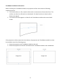
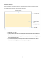
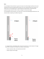
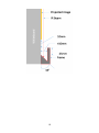
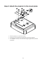
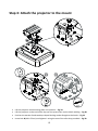
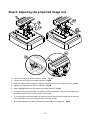
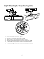
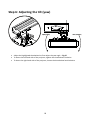
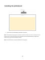
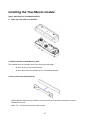
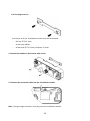
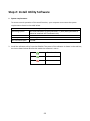
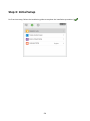
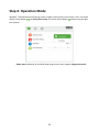
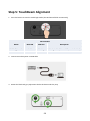
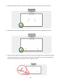
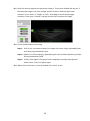
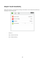
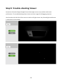
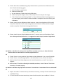
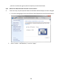
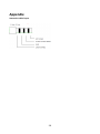
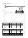
TouchBeam Interactive TouchBeam interactive User manual Table of contents Usage Notice…………………………………………………………………………………………………………………………….. 2 Precautions...………………………………………………………………………………………………………………………………….2 How it works…………………………………………………………………………………………………………………………………..2 Package overview……………………………………………………………………………………………………………………….3 Before Installation – Environment Check…………………………………………………………………………………….4 TouchBeam installation information……………………………………………………………………………………………….5 Whiteboard guidelines…………………………………………………………………………………………………………………..6 Measuring projection surface flatness……………………………………….....……………………………………………..10 Installation Guide……………………………………………………………………………………………………………………..11 Installation workflow………………………………………………………………………………………………………………….…11 Installing the mount……………………………………………………………..………………………………………………….….12 Step 1: Attach the wall plate to the wall….………………………………………………………..……………..…………..12 Step 2: Attach the projector to the mount plate.……………………………………………………………..…………..13 Step 3: Attach the projector to the mount…..…………………………………………………………………..…………..14 Step 4: Adjusting the projected image size………………………………………………………………….…..……………15 Step 5: Adjusting the tilt (vertical keystone)...…………………………………………………………………..……..…..16 Step 6: Adjusting the tilt (yaw)…………………....…………………………………………………………………..……..…...17 Step 5: Adjusting the tilt (horizontal keystone)...……………………………………………………………..……..…..18 Installing the whiteboard…………..……………………………………………………………………………………….…...19 Installing the TouchBeam module………………………………………………………………………………..……….….20 Step 1: Mounting the TouchBeam module………………………………………………………..……………..…………..20 Step 2: Install Utility Software………………..………………………………………………………………………..…………..22 Step 3: Initial Setup………………………………..………………………………………………………………………..…………..23 Step 4: Operation Mode…………………………………………………………………………………………………..…………..24 Step 5: TouchBeam Alignment……………….………………………………………………………………………..…………..25 Step 6: Touch Area Setting………………………..……………………………………………………………………..…………..28 Step 7: Calibration………………………………….………………………………………………………………………..…………..30 Step 8: Touch Sensitivity…………..……………….……………………………………………………..……………..…………..31 Step 9: Troubleshooting Viewer……………….……………………………………………………..……………..…………..32 Appendix………………………………………………………………………………………………………………………………….33 Troubleshooting……………………………………………………………………………………………………………………..……33 Interactive cable layout…………………………………………………………………………………………………………………38 Distance Calculator ………………………………………………………………………………………………………………………39 Specification………………………………………………………………………………………………………………………………...41 2 Usage Notice Please follow all warnings, precautions and maintenance as recommended in this user's manual. Warning - Do not disassemble the TouchBeam module. Warning - Do not use, store, or leave the TouchBeam module near fire, or in places with a high temperature, e.g., in direct sunlight, or in sun-heated cars. Warning – Use a standard USB cable (maximum length: 5m). To extend the USB cable length over 5m, a certified active extension USB cable is required. Warning - Do not allow liquid or foreign material to enter the TouchBeam module. Precautions The IR camera on the projector receives infrared signals from the TouchBeam module which is attached to the whiteboard. To operate normally: The IR camera should face the projection area of the whiteboard. Remove any obstacle in between the IR camera and the TouchBeam module. Do not place other infrared communication devices, lighting equipment, or residential heating equipment etc., nearby. Maintenance: Gently clean the optical port with dust blower. How it works TouchBeam covers the entire whiteboard with a thin invisible IR light. When a finger or stylus breaks the TouchBeam, IR light reflects to the IR camera. The camera module tracks multiple touch points and reports positions to a PC or laptop via USB. To optimize the touch function the whiteboard needs to be flat and in good condition, without dents or warping. 3 Package Overview TouchBeam module 2x (M2 6mm) screws 2x (M6 6mm) screws Interactive cable power cable 2x Alignment sticker sticjestickers TouchBeam bracket mounting plate Double sided tape 5m USB cable TouchBeam mounting plate 2x Passive pens CD user manual software 4 Before Installation - Environment Check Before setting up and installing the projector and TouchBeam module ensure that the power supply and wiring work for the installation location of the mount in advance. Note: Install the projector away from other electrical devices such as florescent lights or air conditioners. Some kinds of florescent lights could interfere with the remote control of the projector We recommend to keep source cable length less than 20 meters to reduce external noise We recommend using a steel backed whiteboard Make sure the projector is installed under the following conditions - the projected image is a rectangular shape without any distortion - the projector is tilted at an angle no more than +/-3 degrees vertically and horizontal in relation to the screen When using the interactive function install the projector so that the projected image is within reach Do not install the projector or screen in a location subject to direct sunlight. If the projector and screen are subject to direct sunlight, the interactive function may not operate correctly. 5 TouchBeam installation information Before installing the TouchBeam module, the projection surface must meet the following conditions/criteria: 1. The screen surface is a flat, smooth surface with no unevenness of more than 5mm. The surface can either be a flat wall or a whiteboard. For details on how to check surface flatness see page 8. 2. The surface must be magnetic or allow for the TouchBeam module to be secured with screws If the projection surface meets the criteria above, the projector and TouchBeam module can then be installed in one of the following ways 1. Mount the projector and TouchBeam module to the wall 2. Mount the projector to the wall and attached the TouchBeam module to the whiteboard Image area Image area 6 Whiteboard guideline When installing the TouchBeam module on a whiteboard please follow the guidelines below For standard aspect ratio (4:3, 16:10 and 16:9) image sizes Image size: 70” ~ 115”* From the top of image area, a 20~100mm gap must be kept away from the bottom of TouchBeam module For a whiteboard with a frame height of <3mm, keep a 10mm bezel at left/right/bottom of the projected image area For a regular whiteboard (ex: aluminum frame) with a frame height >3mm, keep a 50mm bezel at left/right/bottom of the projected image area 7 For ultra-wide (24:9) image size Image size: 120” ~ 140” Ultra wide From the top of image area, a 40~100mm gap must be kept away from the bottom of TouchBeam module For a suggested whiteboard with a frame height of <3mm, keep a 10mm bezel at left/right/bottom of the projected image area For a regular whiteboard (ex: aluminum frame) with a frame height >3mm, keep a 50mm bezel at left/right/bottom of the projected image area 8 Note: If the whiteboard frame thickness is greater than 3mm the reflected light interference from the whiteboard frame may be detected by IR camera. This can compromise the touch function. To reduce the risk of this happening it is recommend that a 50mm border is kept around the projected image instead of 10mm as shown in diagram on the previous page. If the whiteboard frame thickness is less than 3mm, ensure the reflected light interference is not observed when completing TouchBeam alignment. It is suggested that a whiteboard with a frame of less than 3mm is used. However if a larger frame size is required it must follow the conditions shown below: - Surface treatment: Matt, with mold texture ≥11010 - Shape: as figure on next page 9 10 Measuring projection surface flatness Criteria: overall surface flatness should have variance of less than 5mm. Equipment: leveling instrument (1.2~1.5m) and thickness gauge. Split projection area into 16 segments equally as shown on chart below. Place leveling instrument on whiteboard. Insert the 5mm thickness gauge at point 1~9 positions following below order: Horizontal: Vertical: - Measure point 1, 2 & 3. - Measure point 1, 4 & 7. - Measure point 4, 5 & 6. - Measure point 2, 5 & 8. - Measure point 7, 8 & 9. - Measure point 3, 6 & 9. Point1 Point2 Point3 Point4 Point5 Point6 Point7 Point8 Point9 If a 5mm thickness gauge cannot be inserted between the whiteboard and the level then the whiteboard is not suitable for finger touch control. 11 Installation guide Installation workflow o Install the projector mount (See mount installation guide) o Attach the projector to mount (See mount installation guide) o Connect sources to the projector o Adjust projected images (See mount installation guide) o Install the whiteboard (See whiteboard installation guide) o Install the TouchBeam module Attach to board Connect to projector / PC Calibrate Note: If the whiteboard is already installed please see page 36. 12 Installing the mount Step 1: Attach the wall plate to the wall For ease of installation mount the bracket on the wall using position 1 and mark other positions using a spirit level. Remove bracket and drill other positions Use fixings suitable for your type of wall construction Use all available fixing points If in any doubt of the suitability of the wall, it’s construction or what type of fixings to use, consult a qualified builder or installer Note: Remove wall plate cover before attaching to wall. Retain fixings for re-attaching cover later. 13 Step 2: Attach the projector to the mount plate Place the projector on a soft clean surface Position the pre-assembled mounting plate on top of the projector Insert 5xA (M4 x 10mm) screws from the fixing kit, tighten with a posidrive screwdriver 14 Step 3: Attach the projector to the mount Lift the projector and mounting plate in to position – Fig 3A Lift the projector so the two hooks slip over the protrusions on the black molding – Fig 3B Position the washer C and teardrop shaped locking washer D against the hooks – Fig 3C Insert bolt B (M8 x 75mm) and tighten it using the one of the allen keys provided – Fig 3D 15 Step 4: Adjusting the projected image size Loosen the two bolts on the projector caddy – Fig 4A Loosen the bot on the fine length adjustor – Fig 4B Slide the caddy and fine adjuster together until the screen size is nearly correct – Fig 4C Tighten the fixing bolt on the fine adjuster – Fig 4D Adjust highlighted bolt to fine adjust the throw distance – Fig 4E To reduce the projected image size, tighten the bolt clockwise using one of the allen keys provided to move the projector closer to the screen To increase the projected image size, loosen the bolt anticlockwise using one of the allen keys provided to move the projector away from the screen Once fine adjustment is done. Tighten the two caddy mounting bolts – Fig 4F 16 Step 5: Adjusting the tilt (vertical keystone) Loosen the single M8 x 75mm bolt – Fig 5A Adjust the projector to the required angle – Fig 5B Tighten the bolt to lock the angle of the projector – Fig 5C Adjust the highlighted thumbwheel to fine adjust the tilt angle – Fig 5D To decrease the angle of projection, tighten the thumbwheel clockwise To increase the angle of projection, loosen the thumbwheel anticlockwise 17 Step 6: Adjusting the tilt (yaw) Adjust the highlighted thumbwheel to fine adjust the yaw angle – Fig 6E To lower the left hand side of the projector, tighten the thumbwheel clockwise To lower the right hand side of the projector, loosen the thumbwheel anticlockwise 18 Step 7: Adjusting the tilt (horizontal keystone) The projector mount is pre-tensioned and can be rotated by hand Adjust the highlighted thumbwheel to fine adjust the rotation of the projector – Fig 7A To bring the left hand side of the projector closer to the screen, tighten the thumbwheel clockwise To bring the right hand side of the projector close to the screen, loosen the thumbwheel anticlockwise 19 Installing the whiteboard Please refer to the whiteboard installation instructions Note: The whiteboard and projector should be installed centrally to each other. The bottom of the image must be a minimum of 10mm from the bottom of the whiteboard border. Enough room must be left on top for the TouchBeam module. Note: If the whiteboard is already installed please see page 36 20 Installing the TouchBeam module Step 1: Mounting the TouchBeam module 1. Open top cover with a screwdriver. 1.2 Mount bracket to whiteboard or wall The module must be installed away from the projected image - At least 13.5cm from the base plate - At least 10cm from the bottom of the TouchBeam module 1.3a For short-term demonstration: Adhere double-sided tape (enclosed in accessory box) onto bracket, then paste onto the whiteboard or wall. Note: 7.5 – 13.5cm from bottom of base plate 21 1.3b For long-term use: Use screws to fix the TouchBeam bracket onto the whiteboard: - Drill tip: Φ O=2.3mm - Screw type: M3x6L - Screw head: Φ O<5.5mm, thickness <2.5mm 1.4 Attach the module to the bracket with screws 1.5 Connect the interactive cable into the TouchBeam module Note: The right angle connector must plug into the TouchBeam module. 22 Step 2: Install Utility Software 1. System requirements To ensure normal operation of the touch function, your computer must meet the system requirements shown in the table below. Operating system CPU Memory Min. hard disk space System requirement Microsoft Windows XP (SP3)/Windows 7 (32bit/64bit)/Windows 8 (Must be installed. NET Framework 4.0) Intel® Core™ i3 or above 2GB or higher 110 MB 2. Install the software utility from the CDROM. The status of the software is shown in the task bar, the icons shown below describe the mode the software is set to: Touch mode Pen mode Disconnected 23 Step 3: Initial Setup For first time setup, follow the installation guide to complete the installation procedure ( 24 ). Step 4: Operation Mode Windows 7 and Windows 8 operating systems support multi-point touch control. Users can select default Touch Mode ( pen (IR pen). ) for multi-point touch, Or switch to Pen Mode ( ) when using the light Please note: Windows XP and MAC operating systems only support single-point touch 25 Step 5: TouchBeam Alignment 1. Press the button to switch to visible light mode (The Red LED will blink continuously) LED indicator Mode Blue LED Red LED IR Laser mode Solid -- Visible light mode Solid Blinking Error -- Solid Description IR laser ON Visible light ON (IR Laser OFF, touch disabled) Error of LD module occurred. 2. Connect PC and Projector via USB cable 3. Rotate the black and grey adjustment knobs clockwise until they stop 26 4. Rotate the grey knob counter-clockwise, until both beams are symmetrically at the same level. 5. Rotate black knob counter-clockwise, move beams downwards until they hit whiteboard frame. 6. Check the beam height with alignment the sticker for both left and right beams. The beams should be located within the grey strip. You will see a little red dot on the dark grey line. Use the black and grey knobs to adjust the beams to locate them on the alignment sticker. 27 7. Press the button again to switch back to IR mode (The Blue LED will stay solid) LED indicator Mode Blue LED Red LED IR Laser mode Solid -- Visible light mode Solid Blinking Error -- Always ON Description IR laser ON 8. Put top cover back on and tighten the screws. 28 Visible light ON (IR Laser OFF, touch disabled) Error of LD module occurred. Step 6: Touch Area Setting A. Select Auto Touch Area Setting: Note: Quit all software applications Reduce ambient light Do not obstruct or shake lens during Touch Area Setting Check if projection image is clear. If not, adjust focus to sharpen the image If fail message pops up, switch to Manual Touch Area Setting. B. Select Manual Touch Area Setting: 29 B-1. After the camera captures the projection image, a Touch Area window will pop up. If the captured image is not clear enough, please re-select “Ambient light mode selection” from “Auto” to “Bright” or “Dim” according to actual ambient light condition. Then press “Preview” and the camera will re-capture the image. B-2. Touch Area Boundary Fine-tuning Step 1: Click on P1, use mouse to drag P1 to upper left corner. Align adjustable green zone with projected white frame. Step 2: Adjust P2 to P4 accordingly; adjustable green zone should completely overlaps the projected white frame. Step 3: Finally, check again if the green frame completely overlaps the projected white frame. If not, fine-adjust again. B-3. When the Touch Area is correctly located click “close” to exit. 30 Step 7: Calibration A. Select Auto Calibration Note: If the fail message pops up, follow the steps shown below to troubleshoot the issues. Close all software applications Reduce ambient light Do not obstruct or shake lens during calibration Check if projection image is clear. If not, adjust focus to sharpen the image If the Auto Calibration fail message still pops up on screen, switch to Manual Calibration. B. Select Manual Calibration: Note: Manual Calibration is suggested for better accuracy. 31 Step 8: Touch Sensitivity When touch function is unresponsive or writing is intermittent. You can adjust the sensitivity by adjusting Touch Sensitivity level: - Default: 4 - Max.: 10 (most sensitive) - Min.: 0 (least sensitive) 32 Step 9: Trouble-shooting Viewer Sometimes infrared red light (IR light) from ambient light sources may interfere with touch performance. The troubleshooting viewer shows real time images for debugging purposes. Use the tab on the left side of the screen to switch to IR light viewer. Any infrared light interference is now shown in the window. 33 Appendix Troubleshooting Q1 Why won’t the PC boot when the USB cable is connected to the projector? A: 1. Unplug USB cable from PC; or 2. Go to BIOS setup page of PC and modify the “Boot priority order.” Choose Hard disk as top priority, save the change and reboot PC. Q2 What to do when Windows system cannot identify the USB device? A: 1. Unplug/re-plug in the USB cable and check again. 2. Switch to another USB port and check again. 3. Restart your computer and check again. 4. Go to Power Options in Control Panel, check USB selective suspend settings status in USB settings under Advance Settings. Switch to “Disabled”. 5. Go to the official website of the laptop/PC manufacturer, and update the USB driver to the latest version. 6. Use the USB cable included with your projector and check again. If a USB extension is needed please contact your distributor. 7. The USB port of your computer may not be working. Please contact your IT staff. 34 Q3 Why is the utility icon ( ) red and not green ( / )? A: Red icon ( ) indicates a failed connection. This may be caused by the following: 1. Unplug/re-plug in the USB cable and check again. 2. Switch to another USB port and check again. 3. Restart your computer and check again. 4. Go to Power Options in Control Panel; check USB selective suspend settings status in USB settings under Advance Settings. Switch to “Disabled”. 5. Go to official website of the laptop/PC manufacturer, and update the USB driver to the latest version. 6. Go to official website of the laptop/PC manufacturer, and update the BIOS driver to the latest version. 7. Use the USB cable included with your projector and check again. If an USB extension is needed, please contact your distributor. 8. The USB port of your computer may not be working. Please contact your IT staff. Q4 What to do when there is only single touch point? A: 1. Re-plug USB cable from PC. 2. Go to “Control Panel” and make sure “Tablet PC Components” is selected. 35 Q5 When should Calibration and Touch Area Setting be completed? A: Please perform Calibration and Touch Area setting during first installation. If the projector or whiteboard is moved, Touch Area Setting and Calibration should be performed again. When Laptop/PC resolution is changed, calibrate again. For better accuracy, please complete manual calibration. If an overlarge offset is observed, please perform Manual Calibration and see Step 8 Calibration for troubleshooting. Q6 What to do when Auto Calibration and Auto Touch Area Setting both fail? A: 1. When the projectors OSD message is shown, this may result in Auto Calibration failure and Auto Touch Area Setting failure. Please wait until the OSD message is hidden before performing Auto Calibration and Auto Touch Area Setting. 36 2. Please follow the troubleshooting steps shown below to perform Auto Calibration and Auto Touch Area Setting again. a. Quit all software applications b. Reduce ambient light c. Do not obstruct or shake lens during Calibration d. Check if projection image is clear. If not, adjust focus to sharpen the image. e. If the “Auto Touch Area Setting failed” or "Auto Calibration failed" message pops up on screen again, please switch to Manual Mode to complete Touch Area Setting and Calibration. 3. Please check Projector Brightness Mode selection. Lower lamp brightness (ECO mode) may affect both Auto Touch Area Setting and Auto Calibration. Please switch to Bright mode to complete Touch Area Setting and Calibration. 4. Please check Projector Display Mode selection. To ensure accuracy of both Auto Touch Area Setting and Auto Calibration, it is suggested to switch display mode to Bright Mode. Q8 What to do when the mouse cursor ( ) flashes or jumps on screen, or when the Touch function does not work well for a certain projection area? A: 1. Check if there is strong ambient light shown on the whiteboard. If yes, turn off the light. 2. Check if there are any foreign objects on the whiteboard. If yes, remove the object. 3. Refer to Step 6 Laser Beam Alignment for detailed procedures, to see if laser beam is aligned. 4. Refer to Step 7 Touch Area Setting for detailed procedures, check if Manual Touch Area boundary is located properly. Q9 What to do when the projection area corner is insensitive or intermittent lines are observed? A: 1. Adjust the level of Touch Sensitivity to enhance sensitivity, see Step 9 Touch Sensitivity for troubleshooting. 2. If Touch function remains insensitive, please check the optical port condition. If dust or 37 particles are observed, gently clean the optical port with dust blower. Q10 A: What to do when the touch function is not accurate? Touch accuracy may be impacted when the Windows default display has been changed. 1. Go to the setting page <Start menu/Control Panel/Appearance and Personalization> 2. Select “Smaller - 100%(Default) ” and click “Apply”. 38 Appendix Interactive cable layout 39 Distance calculator XGA B A W H Image size D M N 0.219m 0.472m 1.422m 1.066m 1.777m / 70” 0.181m 0.37m 1.57m 0.252m 0.505m 1.521m 1.141m 1.879m / 75” 0.194m 0.38m 1.64m 0.287m 0.540m 1.627m 1.220m 2.033m / 80” 0.207m 0.40m 1.75m 0.354m 0.607m 1.828m 1.371m 2.285m / 90” 0.233m 0.43m 1.92m 0.422m 0.675m 2.033m 1.525m 2.541m / 100” 0.259m 0.45m 2.10m B A W H Image size D M N 0.232m 0.485m 1.830m 1.144m 2.158m / 85” 0.172m 0.36m 1.63m 0.245m 0.498m 1.879m 1.175m 2.216m / 87” 0.176m 0.37m 1.67m 0.261m 0.514m 1.940m 1.212m 2.287m / 90” 0.182m 0.37m 1.71m 0.318m 0.571m 2.155m 1.347m 2.541m / 100” 0.202m 0.40m 1.87m 0.375m 0.628m 2.370m 1.481m 2.795m / 110” 0.222m 0.42m 2.02m 0.403m 0.656m 2.475m 1.547m 2.919m / 115” 0.232m 0.43m 2.10m WXGA 40 1080p B A W H D M N 0.193m 0.446m 1.770m 0.996m 2.031m / 80” 0.179m 0.37m 1.49m 0.244m 0.497m 1.972m 1.109m 2.263m / 89” 0.200m 0.39m 1.63m 0.249m 0.502m 1.992m 1.121m 2.286m / 90” 0.202m 0.39m 1.64m 0.305m 0.558m 2.214m 1.246m 2.541m / 100” 0.224m 0.42m 1.79m D M N Ultra wide* B A W H 0.467m 0.72m 2.857m 1.071m 3.05m / 120” 0.193m 0.39m 1.58m 0.497m 0.75m 2.976m 1.116m 3.18m / 125” 0.201m 0.39m 1.63m 0.527m 0.78m 3.095m 1.161m 3.30m / 130” 0.209m 0.40m 1.69m *longer arm mount required F G H K 0.125m 0.037m 0.125m 0.18 41 Specification I. TouchBeam Touch Module Laser Safety Class 1 Curtain to Screen 20mm ~ 100mm @75”~115” XGA/WXGA/1080p Distance 40mm ~ 100mm @ 120”~140” 16:6 ultra-wide LED Indicator Blue/Red I/O Port Interactive Jack x1 ID Size(W*L*H) 150.0 (W) x 50.0 (L) x 40.0 (H) mm Weight <330g Power Consumption 12V/0.3A Operation Temperature 0℃~+40℃(without cooling fan) Storage Temperature -20℃~+60℃ II. General Specifications Calibration Multi-touch Auto Calibration Manual Calibration 10-touch points (Win 7 and Win8 compliant) Multi-touch Min. Distance ≥40mm Hover (Z-depth) Default hover height is 5.5mm. 70”~100” @XGA (co-operate with TR0.33 UST projector) Working Projection Image 85”~115” @WXGA (co-operate with TR0.27 UST projector) Size 80”~100” @1080P (co-operate with TR0.25 UST projector) 120”~140” @ Ultra-wide 16:6 (co-operate with TR0.25 UST projector) Display mode IR camera hot plug Support Ceiling mode only IR camera cannot support hot plug. Please unplug AC power cord of projector before install IR camera. III. Installation Software Microsoft Windows XP (SP3): Mouse mode supported. Windows 7/Windows 8: Touch mode-10 touch points OS Required: supported and Mouse mode supported (Windows: .NET Framework 4.0 installation is required) System Requirements Max OS X(10.7~10.10) Processor Type Intel CoreTM i3 or above RAM 2GB or higher Min. HHD Space 110 MB 42 43