1
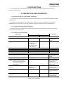
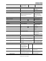
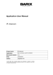
v 2.13 Omnicomm OPTIM terminal Installation manual Vaksali 19, Narva 20308, Estonia. Tel.: +372 3569590, Fax: +372 3566292 , e-mail: [email protected] www.omnicomm-online.com All rights reserved. ©2013 VEPAMON TABLE OF CONTENTS ABBREVIATIONS AND DEFINITIONS ......................................................................................................................... 3 1. INTRODUCTION .................................................................................................................................................. 4 2. DESCRIPTION AND OPERATION ........................................................................................................................... 4 2.1. MODIFICATIONS OF OMNICOMM TERMINALS.............................................................................................. 4 2.2. PURPOSE OF OMNICOMM TERMINALS ........................................................................................................ 4 2.3. TECHNICAL SPECIFICATIONS ......................................................................................................................... 4 2.4. SCOPE OF DELIVERY ..................................................................................................................................... 7 2.5. FUNCTIONS, CONSTRUCTION AND PRINCIPLE OF OPERATION ...................................................................... 7 2.5.1. FUNCTIONS OF Omnicomm Optim terminal .......................................................................................... 7 2.5.2 CONSTRUCTION OF Omnicomm optim terminal ..................................................................................... 9 2.5.3 PRINCIPLE OF OPERATION .................................................................................................................... 10 2.5.4. Omnicomm optim terminal LEDs......................................................................................................... 13 2.5.5. PARAMETERS DETERMINIG THE TRAFFIC VOLUME .............................................................................. 14 2.5.6. PRINCIPLE OF OPERATION OF THE UNIVERSAL INPUTS OF OMNICOMM TERMINAL ............................. 14 2.6. MARKING .................................................................................................................................................. 17 2.7. PACKAGING ............................................................................................................................................... 17 3. INTENDED USE .................................................................................................................................................. 17 3.1. OPERATING LIMITS..................................................................................................................................... 17 3.2. PREPARATION FOR USE .............................................................................................................................. 17 3.3. TYPES OF OPTIONAL EQUIPMENT THAT CAN BE CONNECTED TO OMNICOMM ........................................... 18 3.4. USE OF THE UNIT ....................................................................................................................................... 19 3.4.1. DRIVER USER ...................................................................................................................................... 19 3.4.2. FUNCTIONS PERFORMED BY THE USER ............................................................................................... 19 4. MAINTENANCE ................................................................................................................................................. 19 5. ROUTINE REPAIR ............................................................................................................................................... 20 6. MANUFACTURER’S WARRANTY ......................................................................................................................... 20 REVISION HISTORY................................................................................................................................................ 21 APPENDIX A.......................................................................................................................................................... 22 APPENDIX B .......................................................................................................................................................... 23 2 All rights reserved. ©2013 VEPAMON ABBREVIATIONS AND DEFINITIONS GLONASS – Global Satellite Navigation System of the Russian Federation. PC – personal computer. SW – software. VH – vehicle. GPS (Global Positioning System) – Global Satellite Navigation System of the USA. GSM (Groupe Spécial Mobile) – global digital standard for mobile cellular communication. GPRS (General Package Radio Service) – GSM mobile communication add-on technology for package data transmission. GPRS allows the cellular network user to exchange data with other GSM network devices and external networks, including the Internet. Home network – area within which it is possible to use the services of a given operator without using roaming services. Roaming - procedure for providing cellular services to the subscriber outside the subscriber’s home network coverage area by using the network resources of another mobile operator. Communication server (CS) – server located in the territory of Omnicomm that collects and stores data from the vehicle onboard equipment and transmits data to Omnicomm SW. Omnicomm Autocheck SW – server used to analytically process data received from the CS and the LCS and report on received and processed data. iButton – set of devices for identification of drivers. 3 All rights reserved. ©2013 VEPAMON 1. INTRODUCTION This installation manual describes the construction, principle of operation and operating procedures of Omnicomm Optim terminal. 2. DESCRIPTION AND OPERATION 2.1. MODIFICATIONS OF OMNICOMM TERMINALS Omnicomm Profi and Omnicomm Optim terminals are equipped with unit compatible with GLONASS and GPS satellite systems. Modifications of Omnicomm terminals differ by their design and the type of equipment to be connected. Modification-specific functions and technical specifications of Omnicomm terminals are described below. 2.2. PURPOSE OF OMNICOMM TERMINALS Omnicomm terminals are designed to operate with Omnicomm monitoring system, as well as with the third party vehicle monitoring systems. 2.3. TECHNICAL SPECIFICATIONS Specification General Overall dimensions, mm Value Omnicomm Profi Omnicomm Optim 127.5x100.5x38.0 101.0x90.0x31.5 Ingress protection rating IP51 (when cables are mounted into corrugation) / IP41 (when rubber cable glands are used) Operating temperature, °C -40 to +60 Front panel indication LED Weight, kg 0.2 Operating mode continuous Power supply and power consumption Normal operation range, V +10 to +48 Total operating range, V Power consumption for different data collection modes, W, not more than collect data during pounding; collect data, except GPS; collect all data. Power consumption of the internal heater, W Voltage of integrated power supply, V Load current of built-in power supply, mA, not more than Comments W/o connected cable connectors and wires. IP20 4 LEDs, see par. 3.3 Protection from reverse-polarity voltage. +7 to +60 1.0 2.0 3.0 3 to 11, when supply voltage is 10 to 32 V, respectively 12±0.5 - 350 - - Excluding power supply of LLS sensors, internal heater operation and battery charge current. The heater is activated when the temperature falls below -10°C. Power supply of LLS sensors and external devices. Built-in short circuit protection with selfrestoring capacity. 4 All rights reserved. ©2013 VEPAMON Built-in backup battery Data collection Data collection period Archive capacity, records, not more than Built-in peripherals Real-time clock Accelerometer Temperature sensor 1Wire bus controller Data transmission channel GSM/GPRS Interfaces RS-485 LLS RS-485 TS Runtime not less than 8 hours in standby mode - Li type 15 to 3600 s Set-up during installation Depending on number of collected parameters 150,000 The time calculation error in standalone mode is not more than ±5 min. per year (when disconnected from GPS and GLONASS systems). With stand-alone power supply. Automatic adjustment based on the GPS and GLONASS signals. Three-axis, measurement limit up to ±8 g. Absolute measurement error ±1°C. + - 850/900/1800/1900 MHz Data rate 19,200 bps For connection of LLS 20160, LLS 20230 sensors. For digital camera connection. For PC connection and setup Data rate 115,200 bps 2.0 USB CAN For connection of iButton external reader. Contact or contactless connection to the vehicle electrical system. Voice communication Discrete inputs Ignition key Alarm button Call answering input For connection of the external voice communication headset and speakers. Potential, actuation voltage not less than 8 V. Actuated if the VH is shorted to ground, with internal uncontrolled tightening to power plus. Actuated if the VH is shorted to ground, with internal uncontrolled tightening to power plus From ignition switch. From alarm button. On the voice communication headset or as a separate button. Pulse inputs Velocity Engine speed Frequency fuel level sensor Frequency-modulated signal, input signal frequency 10 Hz to 100 kHz, signal amplitude not less than 5 V. Frequency-modulated signal, input signal frequency 10 Hz to 5 kHz, signal amplitude not less than 5 V. Frequency-modulated signal, frequency 30 Hz to 1054 Hz, signal amplitude not less than 5 V. From pulse velocity sensor. From generator, tachograph or pulse sensor. From LLS-AF 20310 or similar sensors with a frequencymodulated signal. Universal inputs 5 All rights reserved. ©2013 VEPAMON Number of universal inputs Connected signals Analogue signal: Input voltage range Measurement resolution Basic percentage error limit Measurement rate Pulse signal: Pulse frequency Minimum unit pulse duration Input signal amplitude Potential signal: Actuation determination voltage limit Minimum duration of existing voltage that exceeds the threshold for actuation recording Discrete outputs Sound signal 4 2 Analogue voltage signal, pulse signal, potential signal. Inputs are similar and not specially-purposed. The signal type is programmable, connection is made via the same wire 0 to 30 V 10 bits ±1% 1s 10 Hz to 10 kHz 1 μs not less than 5 V Programmable within the range from 1 to 30 V. Actuation (logical unit recording) takes place during data collection if the input voltage exceeds the actuation threshold. 100 μs Supply voltage to output switching, switching current up to 300 mA. Freely controlled discrete output Supply voltage to output switching, switching current up to 300 mA GLONASS + GPS global positioning system Systems in use GLONASS and GPS together, 32 channels Positioning accuracy, m up to 3 Cold start, s not more than 60 Hot start, s not more than 15 Type of antenna Antenna mounting technique external, SMA connector to metal surfaces using the built-in magnet and additionally glued For connection of the sound source. Controlled by incoming SMS-messages Depending on the number of visible satellites. Positioning period upon startup. Positioning period upon short shutdown. To be only installed onto the VH roof or uncovered horizontal surfaces. 6 All rights reserved. ©2013 VEPAMON 2.4. SCOPE OF DELIVERY No. 1 2 3 4 5 6 7 Note: Description Omnicomm OPTIM terminal GLONASS-GPS antenna GSM antenna Mounting parts set Connecting cables set Package Data Sheet Quantity, pcs 1 1 1 1 1 1 1 The following is supplied optionally: alarm button*; CAN alligator clip; * It is recommended to purchase these items from Omnicomm. For detailed description see Appendix B. 2.5. FUNCTIONS, CONSTRUCTION AND PRINCIPLE OF OPERATION 2.5.1. FUNCTIONS OF OMNICOMM OPTIM TERMINAL Omnicomm Optim 1. Measurement of location (spatial coordinates), altitude and velocity of the VH. 2. Data collection from the VH at a preset interval, namely: data from 2 LLS 20160/ LLS 20230 fuel level sensors (fuel level, LLS sensors status, LLS sensors temperature) OR data from 1 LLS-20310-AF fuel level sensor. data from 2 universal inputs; event registration time; ignition key status; engine speed values from pulse sensor or from CAN bus or based on the ignition key position; system voltage; Alarm button input status; acceleration values; data from CAN bus*. 3. Collection of additional location data during turns and slow turns. 4. Data transmission optimization when in home network or roaming. 5. Selection of the data collection and transmission mode when the ignition key is in off position: Collect all data (with data transmission at intervals preset in the Omnicomm). Collect all data, except GPS (with data transmission once an hour in home network and once a day in roaming). Collect data during 5 minutes if accelerometer readings change by 0.2g, with subsequent transmission. 6. Data transmission when the alarm button is pressed. 7. Conversion of data (from engine speed sensor, pulse velocity sensor, pulse universal inputs) to physical values based on calibration and configuration factors. 8. Data reading and conversion to physical values of CAN bus data selected by the user during configuration. 9. Data storage in the internal non-volatile memory before data transmission to the CS. 10. Additional filtration of data from LLS sensors. 11. Recording and transmission of the following data to be displayed in Omnicomm Configurator SW, in addition to the parameters listed above: Time values of the built-in clock. 7 All rights reserved. ©2013 VEPAMON Time values of the GPS/GLONASS system. Internal temperature of the unit. Voltage and number of pulses at pulse and universal inputs. 12. Processing of incoming and outgoing phone voice calls. 13. Adjustment of internal time based on the GPS data. 14. Two-color LED indication of unit statuses and Omnicomm power supply. 15. Processing of incoming SMS. 16. Parameter settings and firmware update via USB interface and via the CS based on the GPRS data. 17. Calculation of mileage based on the GPS data. * Data from CAN bus: temperature of the engine coolant; pressure and temperature of the engine oil; accelerator pedal position [%]; cruise control status; state and position of the foot brake (pedal); engine speed [rpm]; fuel temperature; daily consumption [liter per 100 km]; total consumption during the service life [l]; weight load on the axis; instantaneous efficiency; state of the parking brake (handbrake); state and position of the clutch pedal; mileage [km] (daily/during the service life/before routine maintenance); engine runtime [h] (during the service life/hours before routine maintenance); axis index; instantaneous velocity [km/h]; state of the doors (driver and passenger); state of the driver and front passenger seat belts. 8 All rights reserved. ©2013 VEPAMON 2.5.2 CONSTRUCTION OF OMNICOMM OPTIM TERMINAL Figure 1 – Omnicomm Optim terminal flow chart Microprocessor and Flash-Memory The microprocessor ensures polling of modules and external devices connected to inputs and outputs of Omnicomm Optim terminal. The capacity of Flash-memory is 8 MB. If the data storage module memory is full the processor stops collecting data. Inputs Omnicomm Optim terminals have following inputs: Discrete inputs for the ignition key, alarm button and call answering button. Pulse inputs for the engine speed sensor and LLS-20310-AF frequency fuel level sensor. Two universal inputs for optional equipment. The universal inputs Omnicomm OPTIM terminal is compatible with the following types of signals: Analog signal of DC voltage of up to 30 V Potential signal of DC voltage of up to 30 V; Frequency pulse signal with up to 1000 Hz frequency and up to 30 V amplitude. Satellite navigation. There are two satellite navigation systems simultaneously used in Omnicomm OPTIM terminal: GPS and GLONASS systems. The satellite navigation system module collects the following VH data: location, course, speed, altitude, data validity, time in UTC (Coordinated Universal Time). 9 All rights reserved. ©2013 VEPAMON RS-485 Interface Omnicomm Optim terminals have one RS-485 interface for connection of two LLS 20160 or LLS 20230 sensors. CAN interface. CAN interface allow reading data from CAN bus of the vehicle via FMS or J1939 protocol. The data reading can be either contact, by cutting into wires, or contactless, using CAN alligator clip. GSM module. The GSM module ensures data transmission to the communication server via GPRS channel. Frequency range of the GSM module is of 850/900/1800/1900 MHz. Omnicomm Optim terminal is compatible with SIM-cards of Global mobile operators within frequency range of 850/900/1800/1900 MHz. Voice communication set. Omnicomm OPTIM terminal has the interface for connection of the speaker and microphone from the voice communication headset. Built-in accelerometer. Omnicomm OPTIM terminal has built-in accelerometer to measure acceleration along three coordinate axes and switch to Collect data during pounding mode. Built-in RTC. The reading of the real-time clock is automatically synchronized with the time received from the global positioning system module, once every 15 minutes with the ignition key in ON position. Configuration interface (USB). USB interface is designed for connection of Omnicomm OPTIM terminal to the PC. Indication. Omnicomm OPTIM terminal has four two-color LEDs to indicate different events that take place during unit operation. The designation of LEDs is described in par. 2.5.4. 2.5.3 PRINCIPLE OF OPERATION 2.5.3.1 Data Collection at Preset Intervals and Data Collection on Turns The microprocessor ensures polling of modules and external devices connected to inputs and outputs of Omnicomm OPTIM terminal at preset polling intervals. The value of sensors and modules polling interval varies from 30 to 3,600 seconds and is set through Data collection timer (s) parameter in Omnicomm OPTIM terminal settings using Omnicomm Configurator SW (see Omnicomm Configurator User Manual). The option of data collection on turns allows increase accuracy of turns displayed on the map through additional data collection from the GPS/GLONASS module at shorter intervals than those preset in Data collection timer parameter. 2.5.3.2 Operation upon Pressing the Alarm Button When the alarm button is pressed Omnicomm OPTIM terminal: Immediately transmits data to the communication server; Sends an SMS to the number specified during configuration of the terminal using Omnicomm Configurator software. 2.5.3.3 Data Transmission to the Communication Server If the VH is in the GSM home network, data is transmitted: When Period of data transmission to the CS (home network) preset during Omnicomm OPTIM terminal configuration has elapsed. When the alarm button is pressed. 10 All rights reserved. ©2013 VEPAMON If Omnicomm OPTIM terminal switches to Collect all data mode, except GPS mode once an hour. If Omnicomm OPTIM terminal switches to collect data during pounding mode. If during 5 minutes accelerometer readings changed again by more than 0.2g, data is transmitted every 5 minutes. On command of the SMS sent to the number of SIM-card inserted into Omnicomm OPTIM terminal. If the VH is in roaming, data is transmitted: When period of data transmission to the CS (roaming) has elapsed or when the data volume preset in the Data package volume for transmission to the CS parameter has been achieved, preset during configuration of terminal. When the alarm button is pressed. If Omnicomm OPTIM terminal switches to collect all data, except GPS mode once a day. On command of the SMS sent to the number of SIM-card inserted into terminal. 2.5.3.4. Omnicomm OPTIM terminal Operating Modes In normal power supply mode (the unit is powered by the onboard electrical system, VH battery or external optional battery) and ignition key is ON position Omnicomm OPTIM terminal switches to Collect all data mode. In this case terminal collects data selected during configuration of terminal using Omnicomm Configurator software. For data transmission connection to the communication server is made as preset according to par. 2.5.3.3. In normal power supply mode (the unit is powered by the onboard electrical system, VH battery or external optional battery) and ignition key is in OFF position Omnicomm OPTIM terminal switches to any of the following three modes: Collect all data. In this case terminal collects data selected during configuration of terminal using Omnicomm Configurator software. For data transmission connection to the communication server is made as preset according to par. 2.5.3.3. Collect all data, except GPS. In this case terminal collects data selected during configuration of terminal using Omnicomm Configurator software, except data from the GPS module. For data package transmission connection to the communication server is made once an hour if the VH is in the home network or once a day if the VH is in roaming. If any module is de-energized the unit stops collecting their data. Collect data during pounding. In this case terminal controls the status of the alarm button, accelerometer. If accelerometer readings change by more than 0.2g, the alarm button is pressed; terminal is activated, collects all data selected during configuration and transmits data to the communication server. If during 5 minutes accelerometer readings changed again by more than 0.2g, terminal continues to collect and transmit data to the communication server every 5 minutes. If in 5 minutes accelerometer readings did not change by more than 0.2g and the VH velocity is less than 5 km/h, terminal switches back to control the status of the alarm button and accelerometer. The data collection mode can be selected by setting Operating mode when the ignition key in OFF position and power is on parameter value during configuration of terminal using Omnicomm Configurator software. Omnicomm OPTIM terminal not equipped with the built-in battery does not operate. 2.5.3.5. Omnicomm OPTIM terminal operation with LLS 20160/LLS 20230 and LLS-20310-AF Fuel Level Sensors Omnicomm OPTIM terminal has option of additional filtration of LLS fuel level sensors which can be preset during configuration of terminal using Omnicomm Configurator software. 11 All rights reserved. ©2013 VEPAMON When using LLS-20310-AF fuel level sensor, Omnicomm OPTIM terminal automatically brings frequency range of 30 to 1053 Hz preset during configuration of LLS-20310-AF fuel level sensor to the level measurement scale of 0 to 4095 points. 2.5.3.6. SMS Omnicomm OPTIM terminal processes the following incoming SMS: Request to make connection to the CS (immediately upon receipt of this SMS). Request to send terminal current settings to the CS (immediately upon receipt of this SMS). Request for the following data from the VH (following this, the SMS is sent to the number from which the request was received): current status of the ignition key, current (or last known) velocity, last known location of the VH (without altitude), fuel volume in the tank, system voltage. Request for the status of terminal (following this, the SMS is sent to the number from which the request was received): terminal state, firmware version, number of archived records, time of recent data transmission to the CS, number of satellites, battery voltage. For the description of command formats see Appendix B. 2.5.3.7. Configuration of Omnicomm Optim terminal Omnicomm Optim terminal can be configured using Omnicomm Configurator software. Omnicomm Optim terminal can be connected to the PC via USB interface using USB-mini USB cable. To configure Omnicomm Optim terminal connect USB cable and the mains power cable. Attention! Before connecting Omnicomm Optim terminal to a Notebook via USB interface it is recommended to disconnect PC from the mains and power it from the Notebook battery. If it is impossible to disconnect PC from the mains strictly observe the following procedure for connection of Omnicomm Optim terminal: 1) Connect USB cable to Omnicomm terminal and PC. 2) Connect Side 1 power connector to Omnicomm terminal. Important: Before connecting USB interface you shall disconnect Side 1 from Omnicomm terminal. It is not enough to simply de-energize terminal. During configuration of Omnicomm terminal, already installed on the VH ground, the VH body and the PC housing shall be grounded, if the PC is not powered by the PC battery. During configuration of Omnicomm terminal on the VH, do not disconnect the mass break switch on the VH when you connect USB interface. Failure to observe these requirements can cause damage to USB interface of the PC. 2.5.3.8. Firmware Updates The microprocessor firmware is updated via wired USB interface using Omnicomm Configurator software (see Omnicomm Configurator User Manual) during unit connection to the PC. 12 All rights reserved. ©2013 VEPAMON 2.5.4. OMNICOMM OPTIM TERMINAL LEDS Table 3 LED Power supply, red/green Indication mode Off Flashing, red-green Always on, green Always on, red GPS, red/green Off Always on, green Always on, red GSM, red/green The number of LED flashings depends on number of red LED actuations, following green LED actuation Off Always on, red Always on, green Flashing 1 time (following green LED actuation, red LED lights up 1 time) Flashing 2 times (following green LED actuation, red LED lights up 2 times) Flashing 4 times (following green LED actuation, red LED lights up 4 times) Emergency, red/green Off Value Power is off Power: normal or from USB Ignition: OFF Operating mode: Collect data during pounding Power: normal Ignition: ON or Power: normal Ignition: OFF Operating mode: Collect data, except GPS or Collect all data Ignition: OFF Operating mode: Collect data during pounding In case of module failure Emergency LED lights up Valid data is received from satellites Data is not received from satellites or invalid data is being received Power: normal Ignition: OFF Operating mode: Collect data during pounding In case of module failure Emergency LED goes on Outside the GSM network coverage Within the GSM network coverage; however, without data exchange with the communication sever via GPRS channel SIM-card error or the card is not inserted. Insert or replace the SIM-card The card is blocked (with the PIN code). Unblock the card, disable the PIN code request upon card activation Within the GSM network coverage, with data exchange with the communication server via the GPRS channel, connection The unit operates properly (faultfree) The number of LED flashings depends on the number of red LED actuations, following green LED actuation Always on, red The internal elements of the unit or global positioning system module or GSM module are out of order 13 All rights reserved. ©2013 VEPAMON (broken). Contact the supplier Flashing 1 time (following green LED Configuration failure. actuation, red LED lights up 1 time) Update configuration using Omnicomm Configurator software Flashing 2 times (following green Archive storage failure. LED actuation, red LED lights up 2 Archived data will be lost. Contact times) Omnicomm technical support center Flashing 3 times (following green Failure of data exchange with one or LED actuation, red LED lights up 3 more LLS sensors. times) Check configuration of the LLS sensors, communication line, LLS supply voltage as per LLS 20160, LLS 20230 Installation manual * Note: In case of internal failure (Emergency LED lights up) the satellite navigation system module and GSM module serviceability is indicated by their LEDs. If the LEDS are off and not flashing when the ignition key is in ON position the relevant module is out of order. 2.5.5. PARAMETERS DETERMINIG THE TRAFFIC VOLUME The values of the following parameters set during configuration of Omnicomm Optim terminal using Omnicomm Configurator software determine the traffic volume: 1) The number of data collection parameters selected during configuration of terminal. Only data enabled for data collection is transmitted by terminal. The maximum data package volume is 200 kB. 2) Data collection timer (s) – the period of time after which all sensors connected to Omnicomm terminal and the satellite navigation system module are polled again. When the value of the data collection timer is increased the traffic volume is decreased, leading to a less accurate representation of the route on the map. However, the calculated vehicle motion values are accurate. The recommended value is 30 sec. 3) Enabled adaptive data collection on turns increases the number of recorded events and, thus, increases the traffic volume. Period of data transmission to the CS (min) - the time after which terminal shall establish connection to the communication server. The recommended value for the VHs in the home network is 10 minutes. The recommended value for the VHs in roaming is 180 minutes. Data package volume for transmission to the CS (kB) - the data package volume at which terminal shall establish connection to the communication server while being in roaming. The recommended value is 100 kB. 4) The operating mode of the terminal with the ignition key in OFF position and normal power supply: Collect all data, Collect all data, except GPS or Collect data during pounding. 2.5.6. PRINCIPLE OF OPERATION OF THE UNIVERSAL INPUTS OF OMNICOMM TERMINAL One of the following types of sensors can be connected to universal input: analog sensor with output voltage or output current signal; pulse sensor with output frequency signal; 14 All rights reserved. ©2013 VEPAMON potential sensor. Analog voltage output signal – signal where the measured value of the sensor is proportional to the sensor output voltage. The higher voltage the higher measured value (directly proportional signal) or the lower voltage the higher measured value (inversely proportional signal). Omnicomm terminal can operate with both directly proportional and inversely proportional signals. Sensors that have the output current signal (the most common is 4...20 mA and 0...20 mA signal) instead of the output voltage signal can also be referred to analog sensors. To connect these sensors to Omnicomm terminal install the shunt resistor and measure voltage drop across terminal (i.e. the current signal is converted to the voltage signal that can be sensed by Omnicomm Terminal). The analog voltage signal measured by Omnicomm terminal is converted to the physical value measured by sensor. The conversion is performed linearly based on two points assigned during configuration of Omnicomm terminal. Figure 2 – Assignment of the law for voltage conversion in the measured physical value The measured value averaged over the data collection period and obtained upon linear conversion is transmitted to Omnicomm Autocheck SW. Pulse (or frequency) signal – signal where the measured value is frequency-modulated. I.e. the higher the measured value the higher number of pulses per unit time. For pulse signals Omnicomm terminal summarizes the number of pulses (at the leading edge, i.e. at the signal increase edge) over the data collection period, multiplies the sum by the factor of pulse input calibration and transmits the result to Omnicomm Autocheck SW. The sum is multiplied by the calibration factor for the purpose of conversion of number of pulses in physical value measured by the sensor (for example, the number of pulses can be converted in the engine speed). The pulse signal is also used to count the number of events that take place more often than the data collection period. For example, you can count the number of passengers entering a public vehicle through the doors. In this case Omnicomm terminal summarizes the number of door sensor tripping and transmits the number of passengers entered (or exited) over each data collection interval to Omnicomm Autocheck SW. In this case set the calibration factor to 1, since one sensor tripping corresponds to one passenger. Potential signal – signal indicating the occurrence of any event that takes place less often than the data collection period. The fact that the event occurred shall be recorded, however, the exact time of its occurrence is not important (it is enough to determine the time within the data collection period). Such events can include triggering of any equipment, lowering of actuators of the VH, doors opening etc. The value from the sensor with potential signal is logical: ON (logical unit) or OFF (logical zero). However, this state can exist for the period longer than the data collection period. 15 All rights reserved. ©2013 VEPAMON ON (logical unit) is recorded by Omnicomm terminal if the input of terminal receives the voltage signal that exceeds the actuation voltage threshold and lasts for more than 0.5 s. Potential input ON (logical unit) is transmitted to Omnicomm Autocheck SW as 1000, logical zero – as 0. This is graphically shown in the figure below (Figure4). Figure 4 – Operation of the potential input of Omnicomm terminal If necessary, you can invert the voltage signal before its transmission to Omnicomm Autocheck SW, i.e. ON signal (logical unit) is converted to OFF signal (logical zero) and vice versa. Which type of signal shall be configured – pulse or potential? How to select the type? Configure the pulse signal if you want to count the number of events or triggers, and the potential signal if you want to record the event occurrence, determine the current state of the monitored object and calculate the duration of a certain state of the object. Example: Assume we have a door sensor. To count how often the door was opened during for any period configure the input of Omnicomm terminal as the pulse input. In this case every opening event cause that a nonzero value appears in the data package transmitted to Omnicomm Autocheck SW during the relevant data collection period. However, it will be impossible to determine the period of time during which the door was opened, as well as its current state. To control the period of time when the door is opened and its current state configure the input as the potential input. This is graphically shown in the figure below (Figure 5). 16 All rights reserved. ©2013 VEPAMON Figure 5 – Different output values of pulse and potential types of inputs during processing of the door sensor signal 2.6. MARKING The unit housing is marked as follows: serial number of the unit; trademark or logo of the manufacturer; supply voltage; product designation; ingress protection rating; operating temperature range; 2.7. PACKAGING The unit is packaged with the supplied items in an individual consumer container. 3. INTENDED USE 3.1. OPERATING LIMITS The unit is designed for continuous operation in climatic conditions of enclosed VH cabin. Avoid unit contact with water or other liquids. Protection rating of Omnicomm Optim terminal – IP20. During welding works performed on the VHs equipped with Omnicomm terminals and connected to LLS 20230 fuel level sensors, along with BIS 20240 spark protection units, in order to prevent failure of the terminal, you MUST disconnect cables from SIDE1 and SIDE2 connectors of the terminal and battery terminals. During welding works performed on the VHs equipped with Omnicomm terminal and connected to LLS 20160 fuel level sensors in order to prevent failure of the terminal: disconnect cables from SIDE1 and SIDE2 connectors of terminal and battery terminals (preferred option) connect the second electrode of the welding machine in close vicinity to the welding site and disconnect battery terminals. or 3.2. PREPARATION FOR USE Prepare and connect Omnicomm Optim terminal to the following devices as described in Omnicomm Installation Instructions: optional equipment; engine speed sensor; ignition key terminal; LLS fuel level sensors or one LLS-AF sensor; 17 All rights reserved. ©2013 VEPAMON alarm button; voice communication set; external battery. Configure the unit using Omnicomm Configurator software (see Omnicomm Configurator User Manual). To use voice calls enable the voice calls service on SIM-card inserted into terminal. To use short messages in SMS-messages enable the short message service on SIM-card inserted into terminal. If the VH is operated outside country connect service of international roaming. When using LLS-20310-AF fuel level sensor configure the output signal as the frequency signal and set the maximum and minimum frequency values – 1053 and 30 Hz, respectively. 3.3. TYPES OF OPTIONAL EQUIPMENT THAT CAN BE CONNECTED TO OMNICOMM Depending on the type of optional equipment Omnicomm Optim terminal can display data shown in the table below (Table 4). Table 4 Measured value Fuel, reactants, fertilizers consumption etc. Control of an auxiliary engine speed or any other equipment driven by the power take-off Fuel level in the optional fuel tank or hydraulic liquid tank Number of events that occur more often than the collection period: excavator bucket lifting/lowering, number of public transport passengers, conveyor loading /unloading etc. Fuel level in the auxiliary fuel tank or hydraulic liquid tank Temperature, pressure, humidity etc. Optional equipment on/off (engine, burner, attachments) Sensors/types of sensors Flow meters with pulse output Proximity sensor that determines the shaft (gear, drive etc.) speed Signal type Pulse (frequency-modulated signal the frequency of which is proportional to the measured or recorded value) Sensor of physical values, LLS20310-AF fuel level sensor in frequency output mode Contact switches, proximity sensors triggered by each event Sensor of physical values, LLS20310-AF fuel level sensor in frequency output mode Temperature, pressure, humidity etc. sensors or analog transmitters with output voltage or current signal Proximity sensors, sensors of physical values (e.g. pressure) or other signal sources Contact switches, proximity sensors Number of events that occur less often than the data collection period: taxi passenger boarding, dump truck body lifting, plough lowering etc. Omnicomm Optim terminal has two universal inputs for optional equipment. Analog (voltage or current signal, signal of which is proportional or inversely proportional to measured value) Potential (signal of triggering of any device followed by supply of the specific voltage (potential) across any wire) 18 All rights reserved. ©2013 VEPAMON 3.4. USE OF THE UNIT The unit is operated by two users: Driver and Operator. 3.4.1. DRIVER USER The Driver drives the VH and performs works listed in the job description. Using the alarm button If necessary, it is used to inform the user of Omnicomm Autocheck SW of an emergency the Driver shall press the alarm button. Using the voice communication set by the Driver If necessary, it is used to make outgoing calls via the headset connected to terminal to the number preset during configuration of terminal. An outgoing call is made upon pressing the button located on the headset connected to terminal. Receipt of operator incoming calls. An incoming call is received either automatically or upon pressing the button located on the headset connected to terminal. 3.4.2. FUNCTIONS PERFORMED BY THE USER Data processing using OMNICOMM AUTOCHECK SW Processes the data received from Omnicomm Optim terminal using Omnicomm Autocheck software. Making calls and receipt of driver voice calls Makes outgoing voice calls to the Driver through the headset connected to Omnicomm Optim terminal; Receives voice calls from the Driver. Acquisition of Omnicomm Optim terminal Sends the command for transmission of the following VH data as an SMS: current (or last known) ignition status, current (or last known) speed, the last known coordinates of the vehicle (no height) amount of fuel in the tank, the system voltage. Sends the command for transmission of terminal state as an SMS: firmware version, number of archived records, time of recent data transmission to the CS, number of satellites, battery voltage. For the description of command formats sent by the operator in the SMS see Appendix B. 4. MAINTENANCE The maintenance consists in visual inspection of connecting cables integrity, connectors reliability, antennas reliability, seals and fuses integrity. It is recommended to perform maintenance works at least once a year. Replace integrated power sources every 6 years; 19 All rights reserved. ©2013 VEPAMON 5. ROUTINE REPAIR For replacement or repair send Omnicomm Optim terminal to the manufacturer's service center. In case the Omnicomm Optim terminal is repaired by non-authorized personnel the warranty will be cancelled. 6. MANUFACTURER’S WARRANTY 24 months from the date of original purchase from OMNICOMM (if the other period or conditions did not arranged by special agreements with certain vendor/supplier, or covers the certain territory) providing the user follows transportation, storage, installation and operation rules described in the operating instructions. The warranty period does not cover built-in power sources, including rechargeable ones (batteries). Replace builtin power sources as often as it is required by the relevant operation manual. For replacement send the unit to the manufacturer's service center. 20 All rights reserved. ©2013 VEPAMON REVISION HISTORY Date Version Description 29.04.13 1.13 Initial Release 19.08.13 2.13 Update Optim inputs 11.09.13 3.13 Changed logo 21 All rights reserved. ©2013 VEPAMON APPENDIX A Dimensions of Omnicomm Optim terminal *All dimensions in millimeters (mm) 22 All rights reserved. ©2013 VEPAMON APPENDIX B List and Format of Commands Sent by the Operator in SMS Command SMS command text *SOUND 1# *SOUND 0# *SETDOUT param# Param=0 Param=1 Param=0,1 Purpose SMS command reply *CONNECT# SOUND ON SOUND OFF SETDOUT param Possible parameter values: param = OK if the command was execution param = ER if the command wasn’t execution CRLDOUT param Possible parameter values: param = OK if the command was execution param = ER if the command wasn’t execution DOUT 0=1 1=0 where: output_number=output_status CONNECT CS_address:port *GETLINK# LINK ip4_CS_address:port date_and_time *GETINFO# INFO DID=deviceID VID=VehicleID HW=hardware_code_version BL=boot_loader_version FW=firmware_version REC=number_of_archived_records STAT=terminal_date_and_time GPS=GPS_position SPD=speed IGN=ignition_status L1=fuel_level:sensor_status… L6=fuel_level:sensor_status RESET param Possible parameter values: param = OK if the command was sent for execution param = ER if the command wasn’t sent for execution *CLRDOUT param# Param=0 Param=1 Param=0,1 *GETDOUT# *GETSTAT# *RESET# Request to turn the siren on Request to turn the siren off Request to enable the discrete output sent for sent for Request to disable the discrete output sent for sent for Request for the discrete output status Request to connect terminal to the CS Request for CS connection status Request for terminal status Request for VH status terminal reset 23 All rights reserved. ©2013 VEPAMON