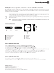
1
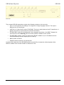
OPERATING INSTRUCTIONS
SIR 800
Compact Transmitter
Printed in Germany
If you have questions about this manual please contact:
beyerdynamic GmbH & Co. KG
Theresienstr. 8
D-74072 Heilbronn , Germany
Phone: +49 (0)7131-617-0
Fax:
+49 (0)7131-617-224
Email: [email protected]
For further information about our products, please go to our website:
http://www.beyerdynamic.de
© 2007
beyerdynamic, Heilbronn
All rights reserved, especially (also partly) the translation, reprint, reproduction through copying or other
similar methods.
beyerdynamic reserves the right to make changes without notice.
Nov-07
SIR Infrared System
SIR 800
CAUTION
DANGER OF ELECTRIC SHOCK
DO NOT OPEN DEVICES
Do not open housing with mains cable connected.
Maintenance operations may only be executed by
qualified personnel.
Our equipment and installations have been built and tested according to the latest state of the art. Under
normal conditions, they do not require any special maintenance.
However, please be aware of the following:
secure and stable position of the installation
sufficient ventilation - never operate equipment near heat sources such as heating radiators etc.
power connection - install all power cables to avoid damaging
connecting cables - avoid trip-traps
liquids - avoid penetration of liquids into the housing
exclusively operate equipment via wall sockets that are connected to ground according to the
relevant specifications and regulations
Warning: Never expose equipment to rain or humidity
Please be also aware of the fact that rough handling of the equipment, such as strong bumps or
vibrations, may result in damages. Inappropriate handling and storage, i.e. handling and storage not in
conformity with the operating instructions, may as well lead to equipment damages.
1
SIR Infrared System
2
SIR 800
SIR Infrared System
SIR 800
Content
1. About this manual .......................................................................................................4
Symbols.................................................................................................................................................................. 4
2. Important remarks......................................................................................................5
2.1 For customers in the EU and in the USA................................................................................................... 5
2.2 For customers in the United Kingdom ....................................................................................................... 5
2.3 Safety .............................................................................................................................................................. 5
2.4 Installation ..................................................................................................................................................... 5
2.5 Cleaning .......................................................................................................................................................... 5
2.6 Repacking ....................................................................................................................................................... 6
2.7 General ............................................................................................................................................................ 6
2.8 Important information ................................................................................................................................. 6
3. Short description..........................................................................................................7
3.1 System function ............................................................................................................................................. 7
3.2 Use ................................................................................................................................................................... 7
3.3 SIR 800 Compact transmitter ..................................................................................................................... 8
4. Installation and starting up ......................................................................................10
4.1
4.2
4.3
4.4
Connecting the LINE-IN socket ............................................................................................................... 10
Connecting RF-LINK socket ..................................................................................................................... 10
Connecting radiator sockets....................................................................................................................... 10
Connecting mains power ............................................................................................................................ 10
5. Starting Up..................................................................................................................11
5.1 Tuning input/output levels ......................................................................................................................... 11
6. OPERATION ..............................................................................................................12
6.1
6.2
6.3
6.4
6.5
LED AF and ON on front side................................................................................................................... 12
Infrared test diodes...................................................................................................................................... 12
Overview....................................................................................................................................................... 13
Technical Data SIR 800 ............................................................................................................................. 14
Optional accessories.................................................................................................................................... 15
Troubleshooting..............................................................................................................16
Warranty ........................................................................................................................17
3
SIR Infrared System
SIR 800
1. About this manual
Symbols
The following symbols and fonts are used in this manual:
Indicates an important note, which has to be followed to guarantee that the functions of the unit,
the security of any data or your health are not put at risk
Indicates additional information, remarks and tips
Describes activities that must be performed in the shown order
Words in bold letters require your special attention.
4
SIR Infrared System
SIR 800
2. Important remarks
2.1 For customers in the EU and in the USA
Our equipment has been tested and complies with the requirement of the CE test. This guarantees the
protection against harmful interferences, when the equipment is operating in a commercial environment.
If the unit is not proper installed to this user manual it may causes radio interferences. Any changes or
modifications not explicit approved in this manual could void your authority to operate this equipment.
2.2 For customers in the United Kingdom
The wires in the main lead are coloured in accordance to the following codes:
Green-and-yellow:
Earth
Blue:
Neutral
Brown
Live
If the colours of the wires in the mains lead of this unit are not corresponding with the coloured markings
of the terminals in your plug, so please proceed as follows:
The green-and-yellow wire must be connected to the plug terminal marked with the letter E, with the
safety earth symbol or with green-and-yellow colour. The blue wire must be connected to the terminal
marked with the letter N or with black colour. The brown wire must be connected to the terminal marked
with the letter L or with red colour.
The equipment must be connected to earth!
2.3 Safety
Check that the operating voltage of the unit is identical with the voltage of your local mains power. If a
voltage conversion is required, consult your beyerdynamic dealer or qualified personnel.
Should any liquid or solid object fall into the cabinet, unplug the unit and have it checked by qualified
personnel before it will be used again. Unplug the unit from the wall outlet or set the Main Power switch
to OFF if it is not used for several days. To disconnect the cord, pull it out holding the plug. Never pull
the cord itself.
2.4 Installation
Allow adequate air circulation to prevent internal heat accumulation. Do not place the unit on a surface
(rugs, blankets, etc.) that may block the ventilation holes.
Do not install the unit in locations near heat sources such as radiators or air ducts, nor in places exposed
to direct sunlight, excessive dust or humidity, mechanical vibration or shock.
To avoid condensation do not install the unit where the temperature may increase rapidly.
2.5 Cleaning
To keep the surface of the housing in a proper condition, periodically clean it with a soft cloth. Large
staining may be removed with a cloth lightly dampened with a mild detergent. Never use organic
solvents such as thinners or abrasive cleaners since these might damage the surface.
5
SIR Infrared System
SIR 800
2.6 Repacking
Save the original shipping box and packing material. For maximum protection, re-pack the unit as
originally packed from the factory.
If not supplied with the equipment, a complete transportation and storage box system is available from
beyerdynamic. We recommend using this system for long-term protection and care.
2.7 General
Please keep this manual together with the compact SIR 800 transmitter. If you hand on the units to third
parties, please include this manual.
Please read the manual carefully, taking special care when you see this symbol as it indicates
important information!
This product is conform to the rules of the following European directive:
89/336/EWG
Council directive to the alignment of the rules of rights of all member states about the electromagnetic
compatibility, modified through RL 91/263/EWG, 92/31/EWG and 93/68/EWG of the council. Further
information is available on request.
The warranty will expire, if you cause defectives through inappropriate use or handling of the unit.
2.8 Important information
The unit should not be used at the maximum volume setting. Adjust the volume to a more
suitable level.
High sound pressure levels will damage your hearing!
6
SIR Infrared System
SIR 800
3. Short description
SIR is a system for the wireless transmission of sound using infrared light. By far the most important
application is in simultaneous interpretation installations, where it is combined with interpreter consoles
from beyerdynamic.
3.1 System function
The SIR system consists of several components:
The central component is the compact SIR 800 transmitter. The inputs are signals from several audio
channels (for instance, several different language channels with simultaneous interpretation). It converts
them into the appropriate FM signals for wireless transmission.
Infrared radiators transmit the information carried by the audio channels in the form of frequencymodulated infrared light.
Within the radiator's area, receivers are used to pick up the information transmitted in the form of infrared
light signals. These receivers feature small dimensions. Headphones are plugged in to listen to their
audio output. Receivers can be moved at will anywhere within the area that is fully illuminated by the
radiators. They can be switched to receive up to 32 channels.
Whenever the SIR system is used as a simultaneous interpretation installation it is operating in
combination with one or several interpreter consoles (e.g. SIS 1202, SID 202, MCS-D 202). The various
languages are fed into the appropriate outgoing channels. The interpreter consoles also include a
number of functions that are essential to ensure the uninterrupted transmission of simultaneous
translation.
These consoles are installed inside sound-proofed interpreter booths.
Interpreters sit inside these booths and use headphones to listen to the original sound, which is normally
called the floor channel. At the same time they speak their translation into an outgoing channel.
Wherever we have a combination of a Microphone system and interpreter consoles it is SIR’s job to
transmit several audio channels wireless to the auditorium.
3.2 Use
In combination with a microphone management system (such as MCS-D), the system can provide the
best communication facilities for organized events that need several languages.
Each and every participant (a term often used is "delegate") can use the microphone system to speak,
and what he or she says will be translated simultaneously so that other delegates will be able to listen to
it in one of the languages. This technique permits direct communication in several languages even at
very large scale events.
It is a simple matter to set up the SIR system in such a way that it is protected against eavesdropping
from outside. Since all information is transmitted in the form of light waves, it is possible to use opaque
material as necessary to limit the area to which it is to be transmitted. Dark curtains drawn across
windows, for instance, are enough to shield a room reliably from the outside world.
Although the SIR system is most commonly used in combination with an interpretation system and
microphone-management system, it is also possible to use it for other purposes.
During organized events, for instance, it is possible to use infrared light to transmit information to individual participants wearing receivers without disturbing anyone else present.
Another example might be museums applications. There it is possible to provide information on
individual exhibits by means of infrared light radiated only to a limited area in front of the particular
exhibit. Visitors listen to the information with receivers and headphones.
These particular operating instructions deal with the combination of SIR systems and interpreter
consoles of the SIS and MCS-D systems. Regarding the operation of these systems, please refer to the
appropriate manuals.
7
SIR Infrared System
SIR 800
3.3 Compact SIR 800 transmitter
Front View
The compact SIR 800 transmitter is part of the SIR system, which serves the wireless language
distribution by means of infrared light.
The sound signal is thereby converted into a frequency-modulated infrared signal and emitted via
transmitting diodes. With special SIR receivers the signal is re-converted into a sound signal, which can
be heard on a set of headphones. Up to 8 channels can be transmitted simultaneously with an FM
narrow band modulation.
The compact SIR 800 transmitter is provided for modulating the sound signals on the different carrier
frequencies and for signal amplification.
The compact transmitter consists of a 19" housing (2HU). Mounting brackets for rack assembly are also
available.
Seven languages and the original (floor channel) can be transmitted.
On the front right-hand side of the compact SIR 800 transmitter there is a green POWER ON showing
the ON/OFF status. Next to this there are three infrared test diodes emitting the IR-signal. With the IR
receiver you can listen to the outgoing channels even without IR-Radiator.
The operating elements of the eight infrared channels are also on the front side of the console.
With miniature-switches on the front panel the frequency band can be chosen and the channels can be
switched ON or OFF. With a rotating switch it is possible to assign up to 32 transmission channels. Each
channel can be set from OR - Ch31.
Eight green LED (“INT”) indicate the status of the corresponding interpreter channel: green LED means
interpreter is “live”. This gives a quick overview about the occupied channels.
8
SIR Infrared System
SIR 800
Rear view
The compact SIR 800 transmitter contains the following sockets on the rear side:
•
Input 1-8: XLR sockets for feeding in the original or foreign language channel. The input is
balanced via AF transformer.
•
LINE IN 1-8: 25-pin Sub-D socket (TASCAM). The input is also balanced via AF transformer. A
signal can be fed in via this socket or the XLR connection.
•
IR-LINK: BNC socket for cascading with other compact transmitters. Use BNC-T adaptor for
more than two units. Warning: Do not connect SIR 801 radiators to this socket.
•
IR-LINE: BNC sockets 1 and 2 for connecting SIR 801 radiators. Up to 10 radiators can be
connected directly at each output (IR Line 1 and 2).
•
Mains power connector.
•
Separate earth connection via special bolt
Unused audio channels of the SIR 800 should be turned off to increase the infrared power of the
SIR 801 radiator for the actual number of channels in use.
9
SIR Infrared System
SIR 800
4. Installation and starting up
The Compact Transmitter has an ex-works mains voltage setting of 90 - 250 Volts by 50 / 60 Hz.
If there is another voltage range you must not connect this equipment. In connecting the system,
special attention is to be paid to ensure that all cables are installed in cable ducts or that they are
fixed by cable clamps or adhesive tape in such a way that there is no danger of somebody tripping over
them.
When installing several SIR 800 above each other, leave 1 U at least free between them.
If the SIR 801 radiator is mounted to the ceiling, please use a safety rope to protect it from falling down.
4.1 Connecting the LINE-IN socket
XLR LINE-IN connector (female): socket for feeding in the original channel or the target
languages.
4.2 Connecting RF-LINK socket
BNC socket for cascading another compact SIR 800 transmitter: To manage more than
8 Outputs you can extend the SIR system with 16 or more line outputs.
4.3 Connecting radiator sockets
BNC 1 and BNC 2: BNC sockets for connecting SIR 801 radiators. Up to 10
radiators can be connected directly.
If there are more radiators needed we recommend using an active CA 5214
distributor.
4.4 Connecting mains power
Connect the delivered cable with this socket to ensure the proper working of
the Compact Transmitter.
10
SIR Infrared System
SIR 800
5. Starting Up
The power supply is turned on via the power switch on the front side of the compact SIR 800
transmitter.
When you use the compact transmitter the first time it is necessary to adjust the provided
channels. This procedure will allocate the transmitter frequencies to the respective channels.
For adjusting this allocation refer to the following figure. The scheme is enclosed with the Compact
Transmitter as a separate sticker which may be adhering to the front panel.
The following allocation is shown on the figure above:
First figure: Channel 1; second figure: Channel 16; third figure: Channel 32
The left DIP-switch 1 will activate the corresponding channel. DIP-switch to ON means channel is active.
DIP-switch has no function.
Do not select the “IF” transmission channel.
5.1 Tuning input/output levels
Before starting a conference situation you should check the sound level in- and output to
avoid level change between floor sound and interpreter sound. This is done by feed in a
test signal to socket “OR-IN” and listening to the corresponding sound level.
Other controls are not necessary for a successful event.
Unused audio channels of the SIR 800 should be turned off to increase the infrared power of the
SIR 801 radiator for the actual number of channels in use.
11
SIR Infrared System
SIR 800
6. OPERATION
Once the SIR system has been properly started up and checked, there is usually no need for any further
intervention from the operator.
Most of the work involved with audio distribution should have been completed during the pre-selection of
channels and system start-up.
6.1 LED AF and ON on front side
AF: This LED indicates a signal on this output (for example line 1).
ON: This LED represents the ON-status of the corresponding output
channel.
Remark: You should switch off not used channels to increase the IR power.
ON- and OFF-status is set with the left DIP-switch.
6.2 Infrared test diodes
Three transmitting test diodes allow testing the receivers at a maximum
distance of 3 meters between the test LED’s and the receiver.
12
SIR Infrared System
SIR 800
6.3 Overview
Power switch
Illustration 1
AF indicator
LED green
ON LED
red
DIP-switch setting
channel range
LINE-IN
3 IR diodes
Mains Power
1-8
Link connector
BNC
Channel
selection
Radiator
connectors
Illustration 2
13
SIR Infrared System
6.4 Technical Data SIR 800
The unit is complying with the international standard IEC914.
Connections
•
Input (8 x XLR sockets)
for input of the original language (OR) and the target languages +6 dBu, balanced
or connection to a 25-pin SUB-D socket (“TASCAM)
•
IR-LINK (2 x BNC-socket)
1: Connection for up to 10 SIR 801 Radiators
2: Connection of up to 10 further SIR 801 Radiators
•
RF-LINK (1 x BNC-socket)
for cascading (RF) with further SIR 800
Features
•
Green lighted mains switch for power ON indication
•
Red LEDs for channel ON indication
•
Green LEDs for audio available (AF)
Transmission frequency
•
55kHz - 1335kHz (channel 31) in 40kHz steps
Intermediate frequency
•
455 kHz
Measurements
•
Distortion: < 0.2%
•
Signal-to-noise ratio: > 70dB
•
Channel separation: > 60dB
Power Supply
•
Mains power: 90 – 250 VAC, 50 / 60 Hz
•
Power consumption: 40 W max
Housing
•
19”, 2 HE, Aluminium, “black” anodized
•
W x H x D: 433 x 88 x 305 mm
Weight
•
14
4.6kg
SIR 800
SIR Infrared System
SIR 800
6.5 Optional accessories
(not included in delivery)
•
SIR 801 Radiator
•
SIR 320 Receiver
•
BNC cable (50 Ohm) different length available
•
CA 5103 BNC-T-adapter
•
CA 5102 BNC-BNC-adapter
•
CA 5101 50-ohm terminating resistor
15
SIR Infrared System
SIR 800
Troubleshooting
Error description
Error cause
Switching
on
the
system The main cable connector is not
produces
no
POWER
ON properly
connected
to
the
condition (green LAMP does not corresponding socket of the unit.
light up).
Connection
cable
possibly
defective.
Error solution
Check if there is no connection to
the mains power.
Replace a new mains cable.
Turn on the POWER ON switch.
The power switch is not in the
correct position.
No clear IR signal at the SIR 320 2 or more channels switched to Check frequency setting on front
receiver
the same frequency
panel and control signal using the
test diodes
16
SIR Infrared System
SIR 800
Warranty
beyerdynamic GmbH & Co. KG provides you with two years’ guarantee on brand-new devices from the
date of purchase. Please save your sales receipt and this guarantee supplement. Without this proof
repairs can fundamentally only be carried out for a charge. The guaranteeing includes materials and
working time for the elimination of demonstrable defects in material or workmanship. The guarantee
claim is void in the case of operating errors, improper operation, electric and mechanical damage, as
well as in the case of improper repairs by unauthorised workshops.
Excluded from the guarantee claim are batteries and rechargeable batteries included in the delivery, as
well as parts that are
subject to natural wear and tear during usage, such as connecting cables, ear
cups, headband pads, etc.
The guarantee can be claimed in all countries in which legal provisions do not stand in the way of the
guaranteeing.
Valid in all countries in addition to the legal provisions are the guarantees provided by beyerdynamic
sales locations.
beyerdynamic rejects any guarantee, if the safety label with the serial number is removed.
beyerdynamic declares itself to agree to exchange or repair defective components due to faulty materials
or manufacturing, dependent on following procedure:
1) The client declares that the fault is not due to empty, discharged, wrongly inserted, or faulty batteries.
2) You may send the defective product to:
beyerdynamic GmbH Service & Logistik Center
August-Häußer-Str. 9
D-74080 Heilbronn
Germany
3) Should it turn out that the fault was caused through inattentiveness or inappropriate use, the service
and shipping charges will be added to the clients account.
17
SIR Infrared System
NOTES
18
SIR 800
SIR Infrared System
SIR 800
NOTES
19
SIR Infrared System
NOTES
20
SIR 800
SIR Infrared System
SIR 800
NOTES
21
beyerdynamic GmbH & Co. KG
Theresienstr. 8
74072 Heilbronn – Germany
Tel. +49(0)7131-617-0
Fax +49(0)7131-617-224
[email protected]
www.beyerdynamic.de
beyerdynamic U.K. Ltd.
17 Albert Drive
Burgess Hill RH15 9TN
Tel. +44(0)1444-258258
Fax +44(0)1444-258444
[email protected]
www.beyerdynamic.co.uk
beyerdynamic Inc. USA
56 Central Ave.
Farmingdale, NY 11735
Tel. +1(631)293-3200
Fax +1(631)293-3288
[email protected]
www.beyerdynamic.com
Non-contractual illustrations. Subject to change without notice.