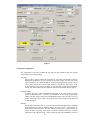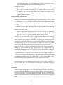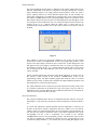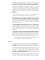
1
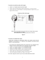
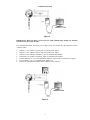
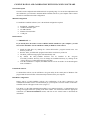
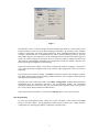
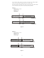
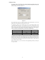
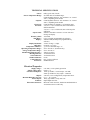
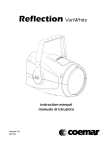
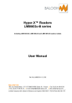
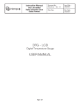
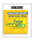
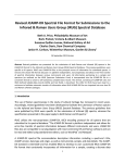
DTG Series
DIGITAL TEMPERATURE GAUGE
User’s Guide
DTG SERIES
DIGITAL TEMPERATURE GAUGE
USER MANUAL
Document No:
DTG_CONFIG USB –
Instruction manual
Software Rev :
2.5
Issue Date:
September 2008
Rev. Date :
November 2009
INTEMPCO CONTROLS LTD.
DTG-CONFIG
INSTRUCTION MANUAL
INTRODUCTION ............................................................................................................................................3
General Description............................................................................................................................................3
Available Models ...............................................................................................................................................3
INSTALLATION .............................................................................................................................................3
Unpacking.....................................................................................................................................................3
Mechanical Installation ................................................................................................................................3
Electrical Installation ...................................................................................................................................3
Connection in stand-alone mode (no output) ..........................................................................................5
Connection in stand-alone mode (with output) .......................................................................................6
Connection in communication mode ......................................................................................................6
CONFIGURATION AND CALIBRATION WITH DTG-CONFIG SOFTWARE ..................................8
General Description .....................................................................................................................................8
Minimal Configuration ................................................................................................................................8
Install software..............................................................................................................................................8
Uninstall software.........................................................................................................................................8
Read DTG configuration ..............................................................................................................................8
DTG Programming ......................................................................................................................................9
Change DTG configuration...................................................................................................................10
Tag Name ........................................................................................................................................10
Calibration Date...............................................................................................................................10
Filtering ...........................................................................................................................................10
Sensor Failure Setting......................................................................................................................11
Change operating range and units .........................................................................................................11
Calibration.............................................................................................................................................11
Output Calibration ...........................................................................................................................12
One-point Calibration ......................................................................................................................12
Two-Point Calibration .....................................................................................................................13
Relay Output .........................................................................................................................................13
LED Display Setting .............................................................................................................................15
TECHNICAL SPECIFICATIONS ...............................................................................................................16
2
INTRODUCTION
General Description
The DTG, Digital Temperature Gauge, features a bright and large 4-digit LED display, optional 420mA output, optional switch output, and an optional RTD (Resistive Temperature Detector) output.
The DTG wetted parts, as well as the housing, are fabricated from stainless 316. The electrical
connection is either extension wires or a Micro-DC male plug. The RTD element used for temperature
measurement is a standard Pt100 ohm. The DTG can be entirely readjusted and recalibrated in all its
operating range by using the USB P-KIT module and the convivial DTG-CONFIG software. The DTG
is a complete solution for most industrial temperature monitoring and indicating applications. It is
designed as a direct replacement for Bi-Metal, Liquid Bulb and Glass Thermometers.
Available Models
The DTG is available with many different mechanical configurations and two temperature limits.
•
•
Hi Temp Model (H) from - 328 to 1112 °F (from - 200 to 600 °C)
Low Temp Model (L) from - 58 to 392 °F (from - 50 to 200 °C)
Consult the catalogue for combinations of the different mechanical assemblies.
INSTALLATION
Unpacking
The DTG is available in the stand-alone version or with the calibration accessories kit. In the standalone version, the DTG is delivered, pre-adjusted and calibrated, only with the instruction manual. In
the calibration version, the complete set includes:
•
•
•
•
•
The DTG gauge (pre-adjusted and calibrated)
The calibration interface module
USB Cable
The calibration software DTG-CONFIG for Windows (CD-ROM) with USB drivers
The instruction manual
Unpack the instrument carefully. Inspect all components for damage. If any damage found, or if
components missing, please notify INTEMPCO representative as soon as possible prior to installation.
Mechanical Installation
The mechanical installation differs for each type of assembly. The same standard installation
procedures as for an RTD assembly must be followed. The INTEMPCO DTG should be located for
easy access for service and monitoring. Sensor electronics and the housing should not be exposed to
temperature below -400C (-400F) or above 700C (1580F). This is very important when process
temperatures are high and heat can conducted up to the enclosure and to the electronics. Special
precaution should be made to prevent exposure to corrosive atmospheres, excessive vibration, shock or
physical damage. It is preferable that the DTG is not installed in proximity to high voltage wires or
other sources of high electrical noise.
Electrical Installation
The DTG is an instrument which, depending on its configuration, comes with 5 or 8 wires. Please refer
to Table 1 and Figures 1 and 2 for color code.
3
5-wire configuration :
** Connector Type : M-12 (5 contacts)
1-Brown (V+)
2-White (Tx)
3-Blue (V-)
1
5
4
2
3
4-Black (Rx)
5-Gey (4-20 mA)
FRONT VIEW
Figure 1
8-wire configuration :
** Connector Type: M-12 (8 contacts)
1-White (Tx)
2
2-Brown (V+)
3
3-Green (Rx)
4
4-Yellow (Relay NO)
1
8
7
6
5
5-Grey (4-20mA)
6-Pink (Relay NC)
7-Blue (V-)
8-Red (Relay COM)
FRONT VIEW
Figure 2
SIGNAL
V+
V4-20 mA
Tx
Rx
Relay – COM
Relay – NO
Relay - NC
5-pin
connector
Brown
Blue
Grey
White
Black
-
8-pin
connector
Brown
Blue
Grey
White
Green
Red
Yellow
Pink
Lead wires
PVC (5)
Brown
Yellow or Blue
Grey
White
Green
-
TABLE 1 – Color code
4
Lead wires
PVC (8)
Brown
Blue
Grey
White
Green
Red
Yellow
Pink
Lead wires
Teflon (5)
Red
Black
Blue
White
Green
*** IMPORTANT ***
If the DTG is not connected to the communication module, the two communication wires (Rx
and Tx) must be isolated from all tension or ground.
The DTG can be connected in stand-alone mode or with the communication module. Figures 3 and 4
show the electrical connection in stand-alone mode and figures 5 and 6, in communication mode.
Connection in stand-alone mode (no output):
•
•
Connect V+ wire of DTG to positive side of power supply
Connect V- wire of DTG to negative side of power supply
Stand-alone Mode without output
NOTE: The communication wires (Tx and Rx) must be left not connected.
Figure 3
5
Connection in stand-alone mode (with output):
•
•
•
•
Connect V+ wire of DTG to positive side of power supply.
Connect V- wire of DTG to negative side of power supply
Connect 4-20mA wire of DTG at positive side of current indicator or measuring instrument
Connect negative side of current indicator or measuring instrument to negative side of power
supply to close current loop.
Stand-alone Mode with output
NOTE: The current indicator must be placed between the output (4-20mA) and the
negative side of the power supply.
The communication wires (Tx and Rx) must be left not connected.
Figure 4
Connection in communication mode:
NOTE: Before connecting the communication module to the computer proceed with the
installation of the USB driver (see “Calibration and Configuration with DTG-CONFIG
Software” section of this manual)
•
•
•
•
•
•
•
•
Do not connect power (USB cable) until all of the steps below have been completed in order,
making sure the last connection made is power (USB cable) to the interface module.
Connect V+ wire of DTG to terminal no 1 (V+) of communication module.
Connect V- wire of DTG to terminal no 2 (V-) of communication module.
Connect Tx wire of DTG to terminal no 3 (Tx) of communication module.
Connect Rx wire of DTG to terminal no 4 (Rx) of communication module.
Connect 4-20mA wire of DTG to the positive side of the ampmeter.
Connect negative side of the ampmeter to negative side of the power supply.
Connect the communication module to the USB port of the computer.
Note: In this configuration, the DTG is powered by the USB communication module.
6
Communication Mode
Figure 5
IMPORTANT: When the DTG is powered by the USB communication module, the maximal
load allowed on the loop is 50 ohms.
In a communication mode, an exterior power supply can be used. In that case, the connection of DTG
is done as follow:
•
•
•
•
•
•
•
Connect V+ wire of DTG to positive side of external power supply.
Connect V- wire of DTG to negative side of external power supply.
Connect Tx wire of DTG to terminal no 3 (Tx) of communication module.
Connect Rx wire of DTG to terminal no 4 (Rx) of communication module.
Connect terminal no 2 (V-) of communication module to negative side of external power supply.
Leave terminal no 1 (V+) of communication module free.
Connect the communication module to the USB port of the computer.
Figure 6
7
CONFIGURATION AND CALIBRATION WITH DTG-CONFIG SOFTWARE
General Description
The DTG can be readjusted and recalibrated in all its operating range. To execute the readjustment and
the recalibration, you will need to install the DTG-CONFIG software on your computer and to connect
the DTG in communication mode configuration.
Minimal Configuration
To install DTG-CONFIG software, here is the minimal configuration required:
•
•
•
•
•
Pentium III – 600 MHz or better
10 MB of Hard Disk space
256 MB of RAM
Windows XP and VISTA
1 USB port
Install software
*** IMPORTANT ***
If you already have the former version of DTG-CONFIG installed on your computer, you will
first need to uninstall it. Use the Add/Remove utility in Windows Control Panel.
•
•
•
•
•
Install the USB driver by running the “CP210xVCPInstaller” program located in the root
directory of the CD.
Run the “DTG_CONFIG.MSI” program located in the root directory of the CD.
The DTG_CONFIG Setup program will automatically start.
By default, the DTG_CONFIG Software will be installed in the “Program
Files\DTG_CONFIG” directory. You can change the installation directory by clicking on the
“Change Directory” button during the setup procedure.
After the installation is complete, the MIST Software will be accessible via the Start-Program
menu of Windows.
Uninstall the software
To uninstall the software, use the Add/Remove Programs utility in the control panel of Windows. The
program and all associated files will automatically be deleted from your computer.
Read DTG Configuration
During start-up of DTG-CONFIG software, the configuration of the DTG connected to the
communication module will be read automatically by your computer. The main window of the DTGCONFIG software will appear on the screen. (Figure 7)
If no DTG is or the USB communication module is not connected properly, a communication error
message will appear before the opening of the main window. You will need to make the appropriate
connection (see Electrical Installation section) and click on the “Read” button to download the
information.
8
Figure 7
The USB driver creates a virtual COM port when the communication module is connected. The virtual
COM port number can be seen in the Device Manager of Windows. By default, the DTG_CONFIG
Software is configured to read on the virtual COM port #1. If the communication module is connected
to another virtual COM port, a communication error will be generated during the start-up. Once the
main window appears, you can then select, in the Configuration section of the main window (upper left
corner), the virtual COM port on which the device is connected (COM1 to COM8) and click on the
“Read” button to download the information. The Configuration section also contains a drop down list
allowing choosing from English to French language.
In this same section of the window, you can find a scrolling menu entitled « Language », which allows
you to select the French or English version of the software. This configuration is also saved for next
utilizations.
The second section of the main window, called DTG, contains the « Read » and « Program » buttons.
The “Read” button activates the downloading of DTG information. The « Program » button opens the
calibration and programming window.
The right side section of the main window, called DTG - Configuration, contains all the information
downloaded from the instrument connected to the communication module. The downloaded
information includes the sensor name (Tag), the serial number, the temperature range, the set point (in
case of relay output option) and the last calibration date.
At the bottom of the main window, a text box named Message shows error or status messages.
DTG Programming
To access the programming window, simply click on the « Program » button located in the DTG
section of the main window. The programming window (Figure 8) allows you to change the DTG
configuration, the operating range and the recalibration of the instrument.
9
Figure 8
Change DTG configuration
The configuration of the DTG includes the tag name, the last calibration date, the filtering
option and the sensor failing setting.
Tag name:
The tag name is used to identify the instrument. It can contain a maximum of eight (8)
alphanumerical characters. To set or change the tag name, simply enter the value in the
text box entitled “TAG” in the GENERAL section of the programming window (top left
corner). If the entered name exceeds eight characters, only the first eight will be saved.
To download the sensor name to the DTG, click on the “SET” button in the GENERAL
section. The “SET” button will also update the calibration date and the filtering option.
Calibration Date:
To modify the value of the last calibration date, enter the new date in the text boxes
entitled « Calibration Date », located in the GENERAL section of the programming
window. The date must be entered in Year/Month/Day format. Once the date is correctly
entered, click on the “SET” button. The “SET” button will also update the tag name and
the filtering option.
Filtering :
The filtering option allows the user to set the response time of the digital filter embedded
in the DTG. There are four (4) different settings. The first, « None », corresponds to an
almost instant output time delay. The other settings correspond to 1, 3 and 5 seconds. To
change the filter’s time delay, click on the selection box entitled « Filtering », chose the
appropriate value and click on the « SET » button located in the GENERAL section of
10
the programming window. It is recommended to set the filter at 1 second. The « SET »
button will also update the sensor name and the calibration date.
Sensor Failure Setting:
The sensor failure setting stands for the output value at which the transmitter will be set
to if a failure is detected on the RTD. The two available choices are “Low”, which
corresponds to a 2,5 mA output, and « High » which corresponds to a 24 mA output. To
set the failure value, click on the Option button, in the “Sensor Failure Settings” section,
matching your choice and then click on the « SET » button located in the same section to
update the setting in the DTG.
Change operating range and units
The DTG can be readjusted in its temperature range at any moment. The user can chose from a
list of thirteen (13) different preset ranges or manually enter the values and preserve the factory
precision standard of ± 0,4 % on any range. This section of the software, entitled OPERATION
RANGE, also allows the user to change the temperature units from Celsius to Fahrenheit, and
vice versa.
To change the temperature units, simply click on the selection box entitled « Units » and chose
the desired value. Once the value is chosen, click on the « SET » button located in the
OPERATION RANGE section.
NOTE : Changing the temperature units or the operating range will reset all the high
precision calibrations at one or two points previously executed, but the measure
precision of ± 0,25 °C + 0,4 % set by default in factory will be preserved.
Every time you click on the « SET » button of the OPERATION RANGE section, a message
will appear on the screen to warn you that the calibration parameters will be lost. You can then
chose to continue or not with the new settings. When units change, the numerical values of the
operating range stay the same since only the temperature units change. (For example, if a DTG
is configured from 0 to 100 °C and the units are changed in Fahrenheit, the instrument will then
be configured from 0 to 100 °F.) Once the units are changed, the values in the « Preset
Ranges » selection box change automatically to correspond to the new temperature units.
To readjust the DTG to one of the predefined ranges, simply click on the « Preset Range »
selection box, chose the appropriate range and click on the « SET » button located in the
OPERATION RANGE section. Once the new range is set, the « Actual Reading » located at the
bottom of the programming window will be updated with the new values.
To readjust the DTG to a range that is not included in the « Preset Range » selection box,
simply enter, in the chosen temperature unit, the values corresponding to output of 4 and 20 mA
in their respective text boxes. To validate this new range, click on the « SET » button located in
the OPERATION RANGE section. Once this new range is set, the “Actual Reading” section,
located at the bottom of the programming window, will be updated with new values.
If the chosen range exceeds the fabrication limits of the DTG, an error message will appear on
the screen and the DTG will not accept the new setting. Bear in mind that changing the
operating range or the temperature units will reset all the calibration values.
Calibration
The DTG-CONFIG software allows you to execute three types of calibration. The first type is
the output calibration, which allows the user to calibrate the DTG output against a current
indicator. The second type is a one-point calibration, which allows the user to calibrate the DTG
for a known temperature value in the operating range. Finally, the third type is a two-point
calibration, which allows the user to calibrate the DTG at two known points in the operating
range.
11
Output Calibration
The output calibration function allows a calibration of the current output against current
indicator, independent of the detector’s temperature. All DTGs already have a factory
output calibration against a very high precision current indicator. If the user wants a
perfect symmetry between its current indicator and the DTG, he can recalibrate the
output. This recalibration is executed firstly by clicking on the “4 mA” button located in
the OUPUT CALIBRATION section of the programming window. It will impose to the
DTG output a theoretical value of 4,00 mA. A little dialogue box will then appear on the
screen (Figure 9) and will allow the user to set exactly the output current to 4,00 mA by
clicking on the (+) or (-) buttons. When the output value is exactly 4,00 mA, as
measured by the current indicator, click on the « SET » button to store the new value in
the DTG.
Figure 9
Next, calibrate to 20 mA. To execute the calibration, click on the « 20 mA » button
located in the OUTPUT CALIBRATION section in the programming window. It will
impose to the DTG output a theoretical value of 20,00 mA. A little dialogue box will
then appear on the screen (Figure 9) and allow the user to set exactly the output current
to 20,00 mA by clicking on the (+) or (-) buttons. When the output value si exactly 20,00
mA, as measured by the current indicator, click on the “SET” button to store the new
value in the DTG.
Finally, calculate and store the parameters of the output calibration. To do this, click on
the “Process” button located in the OUTPUT CALIBRATION section of the
programming window. The DTG-CONFIG program then reads the values of 4 and 20
mA that were previously set in the DTG, calculates the output calibration parameters and
downloads the new values in the DTG memory.
The output calibration can be executed at any moment and not necessarily in this order
(it is possible to adjust the 20 mA before the 4 mA). If necessary, only one of the two
adjustments can be executed. When the output calibration parameters are calculated, the
values are retrieved from the DTG’s memory.
One-point Calibration
The one-point calibration allows the user to compensate the DTG output as well as the
LED display, so they perfectly correspond to a known temperature to which the DTG is
set.
To execute this calibration, a known and stable reference temperature is necessary. Set
the DTG to this known reference temperature and wait 5 minutes to be sure that the
reading is stable. To establish which output current corresponds to this temperature, the
user can enter the reference temperature value (in the chosen temperature unit) in the
corresponding text box (« For a temperature of ») located in the 1-POINT
CALIBRATION section in the programming window. The theoretical output current
will then be automatically calculated and displayed in the corresponding text box
(« theoretical output should be »). You can also rely on the reading that appears on the
12
LED display. If the current displayed by the current indicator, or the reading of the LED
display, do not correspond to the reference value, click on the (+) or (-) buttons of the
“Adjustment” section to adjust the reading of the output to the right value. Each time
you click on the (+) or (-) buttons, the new value is downloaded in the DTG’s memory.
NOTE : The « Actual Reading » section located at the bottom of the 1-POINT
CALIBRATION section displays the values calculated by the DTG-CONFIG program.
This calculation is based on a digital measure (by means of the USB) and cannot exactly
correspond to the current output read by the current indicator or the LED display. For
more precision, use the current indicator’s measure or the LED display to make
adjustments.
Two-Point Calibration
Two-point calibration allows the user to calibrate the DTG for two known reference
temperatures in the operating range. The calibration is executed in three steps.
First step: Reading of first point (« First Point »). The DTG must be at a known and
stable reference temperature located in the operating range. The first point must have a
value inferior to the value of the second point (« Second Point »). Once the value of the
DTG’s output is stable, enter the temperature value in the « First Point » text box located
in the 2-POINTS CALIBRATION section, and click on the corresponding « Read »
button. The entry value is then stored in the DTG’s memory, like the reference
temperature for the first point.
Second step: Reading of second point. The DTG must be at a known and stable
reference temperature located in the operating range. The second point must have a
value superior to the value of the first point. Once the value of the DTG’s output is
stable, enter the temperature value in the « Second Point » text box located in the 2POINTS CALIBRATION section, and click on the corresponding « Read » button. The
entry value is then stored in the DTG’s memory, like the reference temperature for the
second point.
Third and last step: Calculate the calibration parameters. This calculation is executed by
clicking on the “Process” button located in the 2-POINTS CALIBRATION section. The
DTG-CONFIG software will then calculates and downloads the values of the DTG’s
calibration parameters, based on a linear extrapolation between the two stored points.
The new calibration parameters will then be downloaded and stored in the DTG’s
memory. The DTG’s output is automatically recalculated with no resetting required.
NOTE : The reading of the first and second point do not necessarily have to be
executed during the same session or in the indicated order.
Relay Output
The adjustment of the set point for the relay output is executed by entering the numerical
value of the set point in the « Set Point Value » text box, located in the « Relay Output »
section. The units of the set point are in Celsius or Fahrenheit degrees, depending on the
selected units.
The user must then enter the hysteresis value that will be applied to the set point. The
hysteresis level is written in percentage of the operating range. Thus, for an operating
range of 100 °C, 1% represents a hysteresis of 1 °C. This value must be entered in the
« Hysteresis » text box located in the « Relay Output » section. The hysteresis value
corresponds to the temperature at which the relay will return to its normal state. Consult
figures 10 and 11 to understand the mechanism.
Finally, you must choose the operation mode of the relay. The relay can operate in
normal mode, in which it is activated when the set point is reached, or it can operate in
the “fail safe” mode, in which it is deactivated when the set point is reached. To operate
13
in the “fail safe” mode, check the “Fail Safe” box located in the « Relay Output »
section. For the normal mode, simply deactivate the “Fail Safe” option.
Once all the settings concerning the relay output are entered, click on the « SET » button
to store in the DTG’s memory the new relay output operation paramaters.
Example 1 :
Operating Range = 100 °C
Set Point = 50 °C
Hysteresis = 1%
Normal Mode
Relay Activated
Relay Deactivated
49oC
50oC
Temperature
Relay Activated
Relay Deactivated
49oC
50oC
Temperature
Figure 10
Example 2 :
Operating Range = 100 °C
Set Point = 50 °C
Hysteresis = 1%
Fail Safe Mode
Relay Activated
Relay Deactivated
49oC
50oC
Temperature
Relay Deactivated
Relay Activated
49oC
50oC
Figure 11
14
Temperature
LED Display Settings
By clicking on the « LED Display Setup » button, located in the bottom portion of the
programming window, the user will have access to the window allowing him to execute the
different settings on the display (Figure 12).
Figure 12
This window allows the user to adjust the position of the decimal point as well as the
display range corresponding to the output signal 4 to 20 mA.
To modify the position of the decimal point, click on the desired position in the
« DECIMAL POINT SETTING » section, and then click on SET to confirm and store in the
DTG’s memory. If the position of the decimal point does not permit to display the actual
value, the message HI or LO will appear on the display, depending if the value to display is
inferior or superior to the display limits (see table below for display limits)
Position of decimal point
0
1
2
3
Minimal Value
-999
-99.9
-9.99
-.999
Maximal Value
9999
999.9
99.99
9.999
The display range corresponds to the numerical values associated to a signal at 0% of the
operating range and at 100% of the operating range. If, for example, the operating range is
from 0 to 150 °C and that you want a display representing the temperature, enter 0 as the
0% value and 150 as the 100% value. Them click on the SET button to confirm and store
the new display range in the DTG.
When all settings are set, you can come back to the programming window by clicking on
the « Quit » button.
15
TECHNICAL SPECIFICATIONS
Sensor:
Sensor Temperature Range:
Setpoint:
Hysteresis:
Precision:
Open Circuit:
Warm-Up Time:
Time Delay :
Display :
Display Resolution:
RFI effect :
Temperature Influence :
Operating Temperature Range :
Storage Temperature Range :
Maximal Operating Pressure :
Housing Material :
Sensor Material :
Window Material :
Cables Material :
Protection :
RTD, type Pt 100, Class B
See DTG table for standard ranges.
Client adjustable between - 200 and 600 °C or –50 and
200 °C, depending on the model.
Client adjustable between - 200 and 600 °C or –50 and
200 °C, depending on the model.
Client adjustable, by default 1% of operating range.
± (0,25 °C + 0,4 % of full scale) max. with values of
default calibration.
± (0,10 °C + 0,2 % of full scale) max. with one-point
calibration.
Software selectable at 24 mA or 2.5 mA with error
message on display.
30 seconds
0.5 to 5 seconds (programmable by software)
4 DIGIT LED (decimal point programmable by
software).
±0.02% of range ± 1 Digit
Generally 1 % or less
≤ 0,01 % of maximal range / °C
from - 40 to 80 °C (transition only)
from - 40 to 80 °C
500 psi (on probe)
316 Stainless Steel
316 Stainless Steel
Lexan
PVC, Teflon or Silicone
NEMA 4X/IP 65
Electrical Properties
Supply voltage :
Supply voltage effect :
Current Consumption :
Output :
Maximal Resistance of Loop :
Alarm Output :
Isolation :
Electrical Connection :
9-36 VDC, reverse polarity protection
0,005 % / V
15mA @ 24VDC + current output – 950 mW
50mA @ 24VDC for relay output – 1200 mW
4-20 mA (3-wire configuration), temperature linear.
(VAlim. – 9V) / 20 mA
Relay type SPDT 0.5A @ 240 VAC
Input/Output 500 VDC
Micro-DC male connector, aluminium anodized black or
316 Stainless Steel or cable only.
16