1
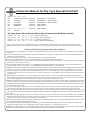
Instruction Manual for Dry-Type Special Clutch Kit
(common among A and B type spindles, and for a motorcycle equipped with M1-14T )
Item No.
Fits:
Fits:
Fits:
Fits:
Fits:
02―02―120
6V Monkey & 6V Gorilla
12V Monkey
12V Gorilla
Monkey BAJA
MONKEY RT
CO
Item No. 02―02―121
Fits:
Monkey R
Frame
Frame
Frame
Frame
Frame
No.
No.
No.
No.
No.
Frame No.
Z50J-1300017 ∼ Z50J-1805927
Z50J-2000001 ∼ / AB27-1000001 ∼
Z50J-2500001 ∼ / AB27-1000001 ∼
Z50J-1700001 ∼
AB22-1007601 ∼
AB22-1000017 ∼
Dry-Type Special Clutch & Close Ratio 5-Speed Transmission Kit (B-type spindle)
Item
Item
Item
Item
No.:
No.:
No.:
No.:
02―03―0001/0002
02―03―0003/0004
02―03―0005/0006
02―03―0007/0008
(Street transmission)
(Super street transmission)
(S-Touring transmission)
(Super close-ratio transmission)
PY
・Thank you for purchasing one of our TAKEGAWA’s products. You are requested to follow the below-mentioned instructions in installing this Kit.
・Before installation, please check the contents of this Kit. Should you have any questions about the product, please kindly contact your local dealer.
Please read the following before starting the installation.
◎ We do not take any responsibility for any accident or damage whatsoever arising from the use of this product not in conformity with the instructions in
this manual.
◎ We shall be held free from any responsibility or compensation whatsoever for any glitch in the parts other than ours if the glitch takes place after the installation and use of this product.
◎ If you make alterations to the product, we shall be held free from any guarantee of the product.
◎ You are kindly requested not to contact us about the combination of our products with other manufacturers’.
◎ This Kit is designed for exclusive use in the above-mentioned fitting models with specified frame numbers only. Please take note that this Kit cannot be
mounted on any other types of motorcycles.
◎For the installation of Item No. 02-02-120 or -121, our TAKEGAWA-made 5-Speed Transmission Kit is necessary. This Kit cannot be installed onto a motorcycle equipped with a stock 4-speed or our TAKEGAWA-made 6-speed transmission, which please note.
◎Installation of this Kit requires splitting of a crankcase and other work. Please do not fail to prepare and strictly follow a HONDA’s genuine service manual
to match your motorcycle. In addition, you need to prepare gaskets like cylinder gaskets and packing suitable for the specifications of your vehicle.
◎ If the friction disk gets covered with water, for example when running in the rain, clutch slippage may occur causing the clutch to be nonfunctional.
If possible, avoid running in the rain, or when driving your motorcycle is inevitable, try to skirt puddles as much as possible to prevent the friction discs
from getting wet.
◎ Water adhering to the friction discs, etc. will corrode these parts, rendering the clutch nonfunctional. Always wipe the water off the friction discs, a clutch plate and other parts and dry them sufficiently after riding in the rain or washing the motorcycle. In the humid or rainy seasons, store your vehicle
with the clutch disengaged to prevent the friction discs, clutch plate or other parts from sticking to each other.
◎Installation of this Kit requires work from removal and mounting of the engine to splitting of the crankcase. At some stages of the installation, some special
tools are required and you need to process some parts. Besides, this Instruction Manual, as well as a service manual, is prepared for those who have
acquired basic skill and knowledge. Therefore, those who are not skilled or do not have sufficient knowledge may not be able to install the Kit correctly,
or in some cases, break the parts.
◎ In the case of Dry-Type Clutch Kit, and if your current mainshaft 1st gear is a 15T close ratio transmission, the mainshaft 1st gear supplied in this Kit is
14T. Accordingly, the 1st gear ratio will change to 2.357 from 2.200. This change of gear ratio, however, does not pose any technical problem.
◎In the case of Dry-Type Clutch Kit, and if your current mainshaft 1st gear is a 13T close ratio transmission and a B-type kick starter is used, a 33T counter
shaft 1st gear (C1-33) and 25TB kick starter pinion (K-25B) are additionally needed for the installation of this Kit. And the 1st gear ratio will change to 2.357
from 2.692.
◎In the case of Dry-Type Clutch Kit, and if your current mainshaft 1st gear is a 13T close ratio transmission and a A-type kick starter is used, a B-Type Kick
Starter Spindle Kit of Item No. 02-04-0011 and 33T counter shaft 1st gear (C1-33) and 25TB kick starter pinion (K-25B) are additionally needed for the installation of this Kit. And the 1st gear ratio will change to 2.357 from 2.692.
◎In the case of Dry-Type Clutch Kit and Close Ratio Transmission Kit, and if an A-type spindle is used, a B-Type Kick Starter Spindle Kit of Item No. 02-04 001 is additionally needed for the installation of this Kit.
◎If this product is installed onto the Monkey RT and a HONDA’s genuine optional protector is installed onto this vehicle, the release arm of this Kit will interfere with the said protector. As a countermeasure, either uninstall the protector, or cut off the interfering portions.
◎Installation of the Oil Cooler Kit requires an optional oil outlet of either 09-07-056 or 09-07-057. And a stock muffler or street-up muffler cannot be installed.
◎ Please note that the descriptions in this manual like illustrations and photos may differ from the actual hardware.
-1-
Dec./16/’
08
The following show the envisioned possibility of injuries to human bodies or property damage as a result of disregarding the following
CAUTION cautions.
・Always try to drive your motorcycle at legal speeds on the public road, abiding by the laws.
(Riding a motorcycle at a speed exceeding the legal speed limit is subject to punishment for overspeeding in violation of the Law.)
・Work only when the engine and muffler are cool. (Otherwise, you will get burned.)
・Prepare right tools for the work. (Otherwise, the installation with improper tools could cause breakage of parts or injuries to you.)
CO
・Tighten the bolts and nuts securely to the specified torque with a torque wrench. (Otherwise, these parts may get damaged or come off.)
・As some products and frames have sharp edges or protruding portions, please work with your hands protected.
(Otherwise, you will suffer injuries.)
・Before riding, always check every hardware for slack in parts like screws. If you find slack ones, screw them securely up to the specified torque.
(Or improper torque may cause parts to come off.)
The following show the envisioned possibility of human death or serious injuries to human bodies as a result of disregarding the
WARNING following cautions.
・Those who lack technical skill or knowledge are required not to do the work.
(Improper installation could lead to a motorcycle's overturning or accidents as a result of parts breakage.)
・Rotating parts in the dry-type clutch, such as a clutch outer, are touchable through an opening in a cover. Please never look into or touch them
when the engine is running. Moreover, be dressed to protect your legs when riding so you do not get your clothes caught in the rotating parts of the
clutch. (Otherwise, the motorcycle may overturn, and you will suffer injury or burn yourself.)
・Always drive the engine in a well-ventilated place, and do not start the engine in an airtight place.
(Otherwise, you will suffer from carbon monoxide poisoning.)
・When you notice something unusual with your motorcycle while riding, immediately stop riding and park your motorcycle in a safe place.
(Otherwise, the abnormality could lead to accidents.)
・Before starting the work, secure your motorcycle firmly on level ground for safety’s sake.
(Otherwise, your motorcycle could overturn and injure you while you are working.)
・Carry out inspection or maintenance of your motorcycle correctly according to the procedures in the instruction manual or service manual. (Improper inspection or maintenance could lead to accidents.)
・If you find damaged parts when checking or performing maintenance of your motorcycle, do not use these parts any longer, and replace them with
PY
new ones. (The continued use of these damaged parts as they are could lead to accidents.)
・As gasoline is highly flammable, never place it close to fire. Make sure that nothing flammable is near the gasoline. Since vaporized accumulation of
gasoline is at high risk of explosion, work in a well-ventilated place.
◎ Please be informed that, mainly because of improvement in performance, design changes, and cost increase, the product specifications and prices
are subject to change without prior notice.
◎ This manual should be retained for future reference, and keep it at hand so you can refer it any time.
∼ Features ∼
・As the clutch is installed on the transmission main shaft, the friction loss of the crankshaft can be reduced, and the crankshaft durability and throttle
response can be improved.
・Being located outside, this clutch mechanism has an excellent cooling effect. Moreover, since the clutch mechanism does not encounter oil resistance,
the clutch disengagement improves.
In addition, this dry-type clutch prevents oil from deteriorating caused by the wear of the clutch discs or the generated heat, and reduces adverse effect on the engine.
・We have designed the number of friction disks to be four so the clutch can match the high-powered engine.
・We have incorporated a damper into the primary driven gear with an aim to reduce the shock felt at the time of clutch engagement.
・We have used a paper-type oil filter to improve the engine oil filterability. And we have created an oil sight window to check the amount of oil left.
-2-
Dec./16/’
08
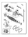
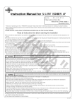
∼ The clutch consists of ∼
8
N
CO
9
10
6
51
52
55
55
54
17
1
56
15
1717
17
18
16
17 17
19
38
37
44
43
15
39A
39B
31
32
PY
33
34
45
46
47
21
29 29
25 25
36
35
29
49
20
26
22
30
23
57
24
25
48
50
28
56
12
11
14
13 53
7
25
29
29
27
27
27
27
29
2
41
42
40,41
5
41
41
41
41
4
3
42
※A component marked “N” shows a genuine part.
-3-
Dec./16/’
08
No.
1
2
3
4
5
6
7
8
9
10
11
12
13
14
15
16
17
18
19
20
21
22
23
24
25
26
27
28
29
30
31
32
33
34
35
36
37
38
39A
39B
40
41
42
43
44
45
46
47
48
49
50
51
52
53
54
55
56
57
58
Part name
Right side crankcase cover COMP.
Clutch cover COMP.
Right side crankcase cover gaskets
Crankcase gaskets (6V)
Crankcase gaskets (12V)
Main shaft
Main shaft first gear (14T)
Thrust washer, 14mm
Primary drive gear (18T)
Lock washer
Conical spring washer
Lock nut COMP.
Bearing seat
Primary driven gear COMP. (67T)
Dowel pin, 8x12
Clutch outer
Flat head screw, 6x15
Seal bearing, 6903
Clutch pressure plate
Clutch plate
Clutch friction disk (Kevlar)
Clutch plate B
Clutch center
External circlip, 17mm
Clutch spring
Clutch lifter plate
Flange hex bolt, 6x22
Clutch release rack
Socket cap screw, 6x15
Clutch cable receiver
Oil filter spring
Oil filter element
O-ring, 40mm
Oil filter cover
Plain washer, 10mm
Clutch arm spring
Flange hex bolt, 6x18
Clutch release arm
Clutch cable COMP., 910mm
Clutch cable COMP., 730mm (Monkey R)
Socket cap screw, 6x70 (12V motorcycle)
Socket cap screw, 6x25
Socket cap screw, 6x30
O-ring, 30mm
Hole cap
Oil pot window COMP.
Oil seal, 60x80x8
Oil seal, 13.8X24X5
Clutch release pinion
Oil seal, 10X17X5
Flat head screw, 4X10
Oil seal, 6X13X5
C-ring, 13 mm
Thrust bearing
Thrust washer
Ball bearing, 6803
Oil seal, 17X28X7
Shield bearing, 6001
Hex wrench, 5mm
CO
Qty
1
1
1
1
1
1
1
1
1
1
1
1
1
1
2
1
6
1
1
5
4
1
1
1
4
1
4
1
6
1
1
1
1
1
1
1
1
1
1
1
1
6
2
1
1
1
1
1
1
1
1
1
1
1
1
2
1
1
1
Repair part item No.
00-02-0068
11650-181-T00
11394-GW8-T01
11191-035-T01
11191-GB4-T01
23212-165-T30
23222-165-T20
00-02-0047
23121-181-T00
90431-001-T00
00-02-0036
90200-181-T00
22301-181-T00
23100-GEF-T00-C
000-03-092
23101-165-T10
00-00-0031
NTN-6903LLB
22351-GEF-T00
22311-165-T00
02-02-0003
22321-GEF-T00
22120-165-T00
00-02-0005
22401-181-T00
22361-GEY-T10
BW-00-0077
00-02-0039
BW-00-0002
22839-181-T00
15413-181-T00
00-02-0027
00-02-0040
15411-181-T00
BW-01-0003
22815-165-T00
00-00-0023
22812-181-T00
22870-181-T20
22870-181-T10
BW-00-0003
BW-00-0005
BW-00-0004
00-01-0034
12361-GEF-T00
00-02-0032
00-02-0044
00-02-0032
23261-28B-T00
00-02-0006
BW-00-0007
00-02-0037
000-03-093
00-02-0061
00-02-0060
00-00-0024
00-02-0020
00-00-0026
In packs of
1
1
1
1
1
1
1
1
1
1
1
1
1
1
3
1
5
1
1
1
5
1
1
5
1
1
4
1
10
1
1
1
1
1
10
1
5
1
1
1
2
10
5
4
1
1
1
1
1
1
6
1
5
1
1
1
1
1
―
PY
※ In the case of a Dry-Type Clutch Kit and a Close Ratio Transmission Kit, the close ratio transmission is included in the Kit. Therefore, those parts which will not be used or overlap each other are excluded from the Kit.
※ In the case of Dry-Type Clutch Kit and Close Ratio Transmission Kit, when you order the repair parts for the close ratio transmission, please quote the Nos in this list for the mainshaft and mainshaft 1st gear, and for other parts, please quote the part Nos in the close ratio transmission.
※ In ordering repair parts, please quote the Repair Part Item No. There are some parts, however, for which we are not in a position to accept your order
in just the quantity to be used. In this case, please take them in the quantity packed.
-4-
Dec./16/’
08
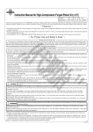
∼ The transmission consists of ∼
24
CO
16
22
12
26
18
23
13
24
17
16 16
14
16
20
19
30
6
20
20
31
32
19
19
9
15
8 32
31
5
21 27
PY
28
25
11 31
N
32
1
4
32
31
2
7 31
32
10
3
29
02-03-0001/0002 (Street)
No.
1
2
3
4
5
6
7
8
9
10
11
Part name
Main shaft
Counter shaft
Main shaft first gear (14T)
Counter shaft first gear (33T)
Main shaft second gear (17T)
Counter shaft second gear (30T)
Main shaft third/fourth gear (20T/22T)
Counter shaft third gear (28T)
Counter shaft fourth gear (25T)
Main shaft fifth gear (24T)
Counter shaft fifth gear (23T)
Qty
1
1
1
1
1
1
1
1
1
1
1
Part name
Main shaft
Counter shaft
Main shaft first gear (14T)
Counter shaft first gear (33T)
Main shaft second gear (17T)
Counter shaft second gear (30T)
Main shaft third/fourth gear (20T/22T)
Counter shaft third gear (28T)
Counter shaft fourth gear (25T)
Main shaft fifth gear (24T)
Counter shaft fifth gear (24T)
Qty
1
1
1
1
1
1
1
1
1
1
1
02-03-0007/0008(Super close ratio)
Repair part item No. In packs of
23212-165-T30
1
23221-165-T11
1
23222-165-T20
1
23421-165-T22
1
23431-051-T01
1
23441-051-T01
1
23451-051-T00
1
23461-051-T10
1
23481-051-T10
1
23491-051-T00
1
23501-051-T00
1
02-03-0003/0004 (Super Street)
No.
1
2
3
4
5
6
7
8
9
10
11
Part name
Main shaft
Counter shaft
Main shaft first gear (14T)
Counter shaft first gear (33T)
Main shaft second gear (18T)
Counter shaft second gear (29T)
Main shaft third/fourth gear (21T/24T)
Counter shaft third gear (25T)
Counter shaft fourth gear (23T)
Main shaft fifth gear (26T)
Counter shaft fifth gear (21T)
Qty
1
1
1
1
1
1
1
1
1
1
1
No.
1
2
3
4
5
6
7
8
9
10
11
Part name
Main shaft
Counter shaft
Main shaft first gear (14T)
Counter shaft first gear (33T)
Main shaft second gear (19T)
Counter shaft second gear (29T)
Main shaft third/fourth gear (21T/23T)
Counter shaft third gear (27T)
Counter shaft fourth gear (26T)
Main shaft fifth gear (24T)
Counter shaft fifth gear (24T)
No.
12
13
14
15
16
17
18
19
20
21
22
23
24
25
26
27
28
29
30
31
32
Part name
Right gear shift fork
Center gear shift fork
Left gear shift fork
Gear shift drum
Dowel pin, 4x10
Gear shift drum side plate
Gear shift drum stopper plate
Gear shift fork guide pin
Gear shift fork guide pin clip
Neutral switch rotor
Shift drum stopper arm COMP.
Shift drum stopper spring
Stopper plate setting pin
Kick starter pinion (25T)
Knock bolt, 6mm
Plain washer, 6X17X2.3
Hex bolt, 6x16
Thrust washer, 14mm
Thrust washer, 13.5mm
External circlip, 17mm
Spline washer, 17mm
Qty
1
1
1
1
1
1
1
1
1
1
1
Repair part item No. In packs of
23212-165-T30
1
23221-165-T11
1
23222-165-T20
1
23421-165-T22
1
23431-165-T00
1
23441-165-T01
1
23451-165-T00
1
23461-165-T00
1
23481-165-T00
1
23491-165-T01
1
23501-165-T00
1
Common Parts
Repair part item No. In packs of
23212-165-T30
1
23221-165-T11
1
23222-165-T20
1
23421-165-T22
1
23431-051-T01
1
23441-051-T01
1
23451-051-T00
1
23461-051-T20
1
23481-051-T10
1
23491-165-T01
1
23501-165-T00
1
02-03-0005/0006 (S-Touring)
No.
1
2
3
4
5
6
7
8
9
10
11
※A component marked “N” shows a genuine part.
Repair part item No. In packs of
23212-165-T30
1
23221-165-T11
1
23222-165-T20
1
23421-165-T22
1
23431-181-T00
1
23441-181-T00
1
23451-181-T10
1
23461-181-T10
1
23481-181-T10
1
23491-181-T00
1
23501-181-T00
1
Qty
1
1
1
1
4
1
1
3
3
1
1
1
2
1
1
1
1
1
1
5
5
Repair part item No. In packs of
00-02-0014
1
00-02-0015
1
00-02-0016
1
24301-181-T12
1
00-02-0049
5
00-02-0018
1
24411-051-T01
1
00-02-0048
3
24263-165-T00
1
00-02-0090
1
00-02-0025
1
24435-GEF-T00
1
00-02-0054
1
28211-165-T20
1
00-02-0013
1
00-02-0050
1
00-00-0032
3
00-02-0047
1
00-02-0055
1
00-02-0005
5
00-02-0023
5
※ In ordering repair parts, please quote the Repair Part Item No. There are some parts, however, for which we are not in a position to accept your order in
just the quantity to be used. In this case, please take them in the quantity packed.
-5-
Dec./16/’
08
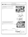
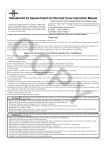
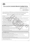
∼ On processing ∼
CAUTION
Always work with gloves on to protect your hands. Otherwise, you may suffer injuries.
CO
Left side crankcase
〇Fold down the circled portion on the left side crankcase with a plier, and
rasp the circled portion with a file or a hand grinder. Then wash the left
side crankcase with water.
※ Cover the bearings with a tape not to get any dirt, dust or chips into them.
※ Work with gloves on lest you should cut your hands with edges of the
case.
Rasp here.
PY
Rasp the shaded area.
mm
About 7 mm
Ab
out
18
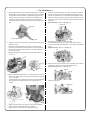
〇 In case a kick starter pinion and a left side crankcase interfere with each other on motorcycles with frame Nos from AB27- onwards, cut off
the circled portion until the gear does not touch it any more.
※ Cover the bearings with a tape not to get any dirt, dust or chips into them.
※ Work with gloves on lest you should cut your hands with edges of the
case.
Rasp here.
Gearshift arm
〇 Rasp the tip of the gearshift arm.
※ Work with gloves on lest you should cut your hands with edges of the
shift arm.
Rasp the shaded area.
Life size
-6-
Dec./16/’
08
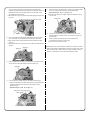
∼ On installation ∼
1.Apply grease to the lips of the oil seal of the left side crankcase shift
spindle. Apply oil to the bearings of the right and left side crankcases.
And place the left side crankcase on the pedestal. Apply oil to the 4.Degrease the mating surfaces of the right and left side crankcases.
And set a dowel pin and attach new gaskets. Put together the right and left side crankcases, and check that the they fit together closely.
rubbing surfaces of the gears on the sides of the mainshaft and countershaft. And mesh together the gears of the mainshaft and countershaft, and fit the hook of the shift fork into the grooves on the
gear.
With the left side crankcase up, place the bolts, and tighten first those
placed in the middle, and then those placed outside but diagonally and
alternately.
Specified torque: 10 N・m (1.0 kgf・m)
CO
Dowel pin
Shift drum
Counter shaft
Gasket
Main shaft
2.Install into crankcase the main shaft, counter shaft and shift drum all
together as a unit.
※ Do above installation with the transmission in neutral, or at the
position where the neutral switch and switch rotor mesh together.
5.Put together the right and left side crankcases.
With the left side crankcase up, place the crankcase bolts on the crankcase, and tighten them diagonally in a few steps to the specified
torque.
Specified torque: 10 N・m (1.0 kgf・m)
PY
※ Never forget to install the thrust washer. As the stock washer is not
to be used, remove it.
※Install the shaft with care so the lip of the countershaft oil seal may not turn up.
Neutral switch
rotor
6V
6.Setting the round corner of the shift drum side washer to face toward
the shift drum, tighten a hex bolt to the specified torque.
Specified torque: 12 N・m (1.2 kgf・m)
Neutral switch
Washer
Hex bolt
3.
Remove, from the kick starter spindle, a 17mm washer, 20mm set ring,
starter drive ratchet, 20mm set ring, 20mm thrust washer and starter
pinion, in this order.
Install the starter pinion included in the Kit onto the kick starter spindle,
and install the above-mentioned parts in the opposite order of
removal.
Install the rubber plug.
Rubber plug
Meshing its friction spring with grooves in the left side crankcase, attach the starter spindle to the left side crankcase.
※ Apply engine oil to the starter pinion and starter spindle.
-7-
Dec./16/’
08
7.Turn around the crankcase so the right side crankcase faces
upwards. And install the kick starter spring and kick spring retainer to
the starter spindle. And fit the spring end into the case with a click. And install the external circlip.
※ Be careful not to get your fingers caught when fitting the spring into
the case.
CO
11.Place the spring in the stopper arm, fit them into the stopper plate
on the case, and tighten the bolt to the specified torque.
Specified torque: 10 N・m (1.0 kgf・m)
※ Be careful not to get your fingers caught when fitting the spring into the case.
Stopper arm
Fit the spring end into the case with a click.
Retainer
Circlip
8.Fit four dowel pins and two stopper plate setting pins into the shift drum, and install the processed gear shift arm onto crankcase.
※Apply engine oil to the sliding surface of the shift spindle and gear shift arm.
※ Apply grease to the lip of the oil seal for the left side crankcase shift
spindle.
Setting pin
Dowel pin
Shift arm
12.Turning the mainshaft with hands, turn the knock bolt on the
stopper plate with a socket wrench, and check if the gears can shift smoothly.
Check that there is some free play in the mainshaft and
countershaft in the direction of thrusting.
※ Do not turn the shift drum forcibly.
PY
◎ Reinstall back the removed parts with reference to the service manual.
Shift the transmission into NEUTRAL, and start the engine. Then check
every component for oil leak. If nothing is wrong, do a test run at slow speed in a safe place to check how the transmission works.
9.Install the shift-drum side plate on the shift drum, meshing the holes
on the shift drum side plate with the shift drum setting pin.
Side plate
10.Fit the shift drum stopper plate into the shift drum setting pin,
keeping the marking on the plate visible. And then, apply thread lock
cement to the thread of the dowel bolt, and tighten it to the
specified torque.
Specified torque: 16 N・m (1.6 kgf・m)
Apply the screw locking agent.
Laser marking
-8-
Dec./16/’
08
∼ On installation ∼
Check the contents of each kit
(Transmission and Dry-Type Clutch Kits)
CO
1.Make sure that your motorcycle is secure on a maintenance stand. Referring to the service manual, demount the engine.
2.Place the removed engine on a working table so it stands stable. And
referring to the service manual, split the crankcase and take out the
transmission.
3.Change the mainshaft for the transmission from the wet-type to the
dry-type.
※In installing each gear, be careful about its direction. Install the M1 gear with the protrusion facing the M5 gear.
4.Install the transmission into the crankcases, replace the crankcase
gaskets with new ones, and fit the crankcases together.
※If your transmission has a 14mm thrust washer between the mainshaft
1st speed gear and crankcase, replace it with a new one. And if your
transmission does not have a 14mm thrust washer, attach one.
5.Referring to a HONDA’s genuine service manual, reinstall the parts removed at the time of splitting the crankcase.
At this point, however, keep the crankshaft and transmission mainshaft
bare of hardware.
2.Fit the clutch bearing seat into the transmission mainshaft.
(Set the bearing seat so its folded portion fits well with the crankcase
so as to prevent it from rotating.)
Then, fit the thrust bearing and thrust washer in this order into the mainshaft.
3.Apply engine oil to the ball bearing of the primary driven gear COMP. ,
and then the grease to the oil seal. And insert the primary driven gear
COMP. into the mainshaft.
※Take off the protective masking tape on the primary driven gear COMP.,
wipe off the tape mark with thinner or the like, and then apply a thin coat of grease to the tape mark.
4.Tighten the lock nut to the specified torque with the crankshaft being
seated in detent.
Specified torque: 39 N・m (4.0 kgf・m)
※After tightening the lock nut to the specified torque, and if the hook on
the lock washer does not fit in the lock nut grooves, turn the lock nut
in the direction of tightening so the hook fits in the lock nut groove.
※ Keep other hooks on the lock washer in close contact with the lock
nuts.
Set the hooks to be in close contact with the lock nut.
PY
(Transmission, Dry-Type Clutch Kit and Close
Ratio Transmission Kit)
1.Make sure that your motorcycle is secure on a maintenance stand. And referring to the service manual, demount the engine.
2.Place the removed engine on a working table so it stands stable. And
referring to the service manual, split the crankcase and take out the
transmission.
3.Referring to the instruction manual for Close Ration Transmission Kit,
install the transmission into the crankcases, replace the crankcase
gaskets with new ones, and fit the crankcases together.
4.Referring to the instructions in the HONDA’s genuine service manual,
reinstall the parts removed at the time of splitting the crankcase.
At this point, however, keep the crankshaft and transmission mainshaft
bare of hardware.
(On installation of the primary gear)
1.
Fit a stock collar into the crankshaft. Then fit a primary drive gear, lock
washer and conical spring washer in this order, and loosely tighten
them for now with a lock nut whose oil seal has been greased.
※ Locate the lock washer and conical spring washer, being careful of
their direction.
Lock washer
Fit the hooks into the lock nut grooves.
(Installation of the right side crankcase cover)
1.Degrease the mating surfaces of the crankcases, and attach the supplied two dowel pins and right side crankcase cover gaskets to
the crankcase.
Apply grease to the lip of the oil seal in the right side crankcase cover.
2.Put in the case straight along the mainshaft so as not to damage the
oil seal of the right side crankcase cover COMP. and that of the lock
nut. Then, temporarily fix the right side crankcase cover onto the crankcase by tightening cap screws from the center of the case to
the outside diagonally to the specified torque.
Specified torque: 10 N・m (1.0 kgf・m)
(Installation of clutch)
1.Put a clutch outer COMP. into the mainshaft, which loosely tighten for
now with a flat head screw. And screw it up diagonally to the
specified torque.
Torque: 10 N・m (1.0 kgf・m)
2.Attach the seal bearing to the mainshaft.
3.To the clutch center, attach a clutch plate B, clutch plate and then clutch friction disk alternately in this order, and install a clutch
pressure plate.
※Degrease the oil on the clutch plate thoroughly, since the oil remaining
on it causes slippage.
※ Check that the clutch center and the clutch pressure plate are
meshing with each other closely.
4.Holding the boss of the clutch pressure plate, align the protruding Lock nut
Drive gear
Turn the lock nut in the tightening
direction so the hooks and
grooves mesh together.
Conical spring washer
(Be careful of its direction)
portion of the clutch friction disk with the clutch outer grooves.
At the same time, align the clutch center with the mainshaft spline, and insert the mainshaft.
-9-
Dec./16/’
08
5.Attach the supplied external circlip to the grooves in the main shaft.
Make sure to place the circlip with the angular side facing out.
※ Do not expand the external circlip more than necessary.
※ If the external circlip does not easily fit into the main shaft grooves,
fit it while pulling the mainshaft with a needle nose plier or the like.
6.Fix the clutch spring to the boss of the clutch pressure plate.
7.Fix the 6x22 hex flange bolt on the clutch pressure plate and tighten
CO
them with hands as hard as possible, with the bearing of the clutch
lifter plate facing outside.
Pull the clutch lifter plate toward you and see if there is a clearance
between the friction disks. If there is a clearance, this shows that the
clutch center and the clutch pressure plate have got out of place with
each other. Therefore, turn the clutch lifter plate to the right and left a
little until they fit each other.
After making sure they fit closely, gradually tighten the 6x22 hex flange bolt diagonally, while pulling the clutch lifter plate toward you.
Finally, tighten them to the specified torque.
Specified torque: 10 N・m (1.0 kgf・m)
※ Do the work carefully so the clutch spring does not get out of place.
(Installation of clutch cables)
(Installation of oil filter cover)
1.Put the oil filter spring into the right side crankcase cover.
Please see to it that it fits in the boss in the crankcase. Also attach the
oil filter, and then fix the oil filter cover by tightening a cap screw to t
he specified torque.
Specified torque: 10 N・m (1.0 kgf・m)
※Place the oil filter so that it sticks into the protrusion on the oil filter cover.
※ Unless the oil filter spring is set correctly inside the protrusion on the
oil filter, there will be a gap between the oil filter cover and the right side crankcase cover COMP.
※ When replacing the oil filter, wipe off the oil on the mating surface of
the O-ring and the oil filter cover, and then apply grease to the O-ring
thinly.
2.Referring to the HONDA’s genuine service manual, reinstall back
all the parts removed at the time of demounting the engine.
3.After checking that the drain bolt is tightened to the specified torque
of { 21.5 N・m (2.2 kgf・m) }, inject 800 cc of engine oil, attach an
O-ring to the hole cap, and tighten it to the specified torque.
Specified torque: 12 N・m (1.2 kgf・m)
※ Apply engine oil slightly to an O-ring of the hole cap.
※In case the crankcase is not to be split (at the time of oil change), add
PY
750 cc of engine oil.
1.Referring to the instructions in the HONDA’s genuine service manual,
reinstall back the parts removed at the time of splitting the crankcase
and mount the engine on the frame.
2.Attach the clutch cable receiver to the clutch cover COMP. with a socket cap screw, and tighten the screw to the specified torque. Specified torque: 10 N・m (1.0 kgf・m)
3.After making sure that a clutch release rack is present inside the clutch cover COMP., fit it securely into the right side crankcase cover
and hold it loosely for now with a cap screw, and tighten the screw
to the specified torque.
Specified torque: 10 N・m (1.0 kgf・m)
※ Apply grease to the clutch release rack.
4.Attach the clutch cable end to the clutch lever.
5.
Route the clutch cable to the receiver, being careful not to stretch it too tight.
6.Slightly apply grease to the clutch cable end, and fit the clutch cable
into the clutch release arm.
※Set and fit the clutch cable so the notch on the clutch release arm faces backward.
7.Screw in the adjuster on the clutch cable to the cable receiver to the
end.
8.Fix into the release pinion the clutch arm spring and release arm with
its inner cable of the clutch cable stretched . Tighten it with a cap screw to the specified torque.
Specified torque: 7 N・m (0.7 kgf・m)
※ Install the release arm by aligning the serrations with each other.
850 cc
800 cc
750 cc
Use above figures just as a guideline on the
oil level at the time of crankcase splitting.
(Inspection after installation)
1.With the engine turned off, shift the transmission to the first gear. Squeeze the clutch lever. Then, check that the rear wheel rotates when you move the machine, and that the rear wheel does not rotate
when you have released the clutch lever.
2.Shift the transmission into NEUTRAL, and start the engine.
Then check each component for oil leak.
If nothing is wrong, do a test run at slow speed in a safe place to check how the clutch works.
If the release arm is pressed inside forcibly without aligning the
serrations, then the release arm will break, getting unusable.
9.Adjust the free play at the clutch with the adjuster on the clutch cable
receiver, then tighten the locking nuts to the specified torque, and cover the clutch cable adjusters at both ends with rubber caps.
Specified torque: 10 N・m (1.0 kgf・m) ※ Adjust the free play at the clutch lever end to be 10 to 20 mm.
-10-
Dec./16/’
08
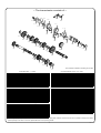
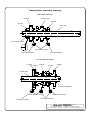
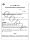
Transmission assembly drawing:
Main shaft assembly
CO
M5 gear
M3 / M4 gear
M2 gear
M1 gear
Main shaft
14mm Thrust washer
PY
17mm External circlip
17mm Spline washer
17mm Spline washer
Counter shaft assembly
C1 Gear
C3 Gear
C5 Gear
Counter shaft
C2 Gear
C4 Gear
13.5mm Thrust washer
17mm External circlip
17mm External circlip
17mm Spline washer
17mm Spline washer
Co.,Ltd.
3-5-16 Nishikiorihigashi Tondabayashi Osaka Japan
TEL : 81-721-25-1357 FAX : 81-721-24-5059 URL : http://www.takegawa.co.jp
-11-
Dec./16/’
08