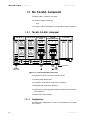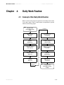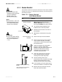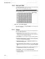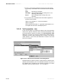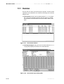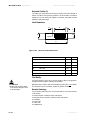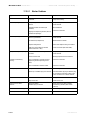
1
Microlab
U S E R
F.A.M.E.
M A N U A L
Version 2.0
Important Notice
This manual may not be used or reproduced in any way whatsoever without the express
written consent of Hamilton Bonaduz AG.
Copyright ã 1995, 1996, 1997, 1998, 1999 Hamilton Bonaduz AG, All Rights Reserved.
Microlab is a registered trade mark of Hamilton Bonaduz AG.
IBM, OS/2, DATABASE 2 and DB2 are registered trademarks of International Business
Machines Corporation.
MICROTITER is a registered trademark of Dynatech Laboratories.
P/N 610520/02 05/01
Microlab F.A.M.E. User Manual V2.0 ——————————————————————————— Master Table of Contents ——
Master Table of Contents
1 - ML F.A.M.E. Overview .................................................................1
Cook Book - Chapter 2 to 8
2 - Cook Book Introduction ............................................................25
3 - ML F.A.M.E. Methods ................................................................27
4 - Daily Work Routine....................................................................41
5 - Test Results & ML F.A.M.E. Traces............................................55
6 - Instrument Status ......................................................................63
7 - ML F.A.M.E. Verification.............................................................65
8 - ML F.A.M.E. Maintenance .........................................................69
Reference Guide - Chapter 9 to 17
9 - Reference Guide Introduction...................................................81
10 - ML F.A.M.E. Methods ..............................................................83
11 - Daily Work Routine................................................................105
12 - Test Results & ML F.A.M.E. Traces........................................129
13 - ML F.A.M.E. Functions & Requirements ...............................137
14 - ML F.A.M.E. Verification.........................................................147
15 - ML F.A.M.E. Maintenance .....................................................169
16 - Technical Specifications........................................................183
17 - Troubleshooting & Error Handling ........................................199
Appendices - A1 to A8
A1 - Error & Trace Codes Messages............................................213
A2 - Glossary ................................................................................237
A3 - Frequently Asked Questions ................................................247
A4 - Anomalies .............................................................................249
A5 - Forms ....................................................................................251
A6 - News Letters .........................................................................261
A7 - User Manual Update Information .........................................263
A8 - Index .....................................................................................265
P/N 610520/02 05/01
Microlab F.A.M.E. User Manual V2.0 ——————————————————————————— Master Table of Contents ——
P/N 610520/02 05/01
Microlab F.A.M.E. User Manual V2.0 —————————————————————————— ML F.A.M.E. Overview ——
Chapter 1
ML F.A.M.E. Overview
Table of Contents
1.1 - About the Microlab F.A.M.E. ....................................................2
1.1.1 - Basic Concepts ..................................................................2
1.2 - Using This Manual....................................................................3
1.2.1 - User Manual Symbols ........................................................3
1.3 - ML F.A.M.E. Components ........................................................4
1.3.1 - The ML F.A.M.E. Instrument ...............................................4
1.3.2 - The ML F.A.M.E. Workstation .............................................9
1.4 - General Information ...............................................................12
1.4.1 - Warranty............................................................................12
1.4.2 - Ordering Information ........................................................13
1.4.3 - Definition of Terms ............................................................17
1.4.4 - Safety Precautions and Hazards......................................17
P/N 610520/02 05/01
1-1
Microlab F.A.M.E. User Manual V2.0 —————————————————————————— ML F.A.M.E. Overview ——
1.1 About the Microlab F.A.M.E.
1.1.1 Basic Concepts
The Microlab F.A.M.E. (ML F.A.M.E.) is a diagnostic instrument
used to analyze blood samples for the presence of certain biological elements.
This analysis is performed using the ELISA (Enzyme Linked
Immuno Sorbent Assay) testing process. This process requires
samples to be manipulated in various ways, i.e. incubating, washing, dispensing, mixing, photometric measurement, etc.
The ML F.A.M.E. has been developed with a modular design, incorporating all functions necessary to perform these sample manipulations.
The test process is controlled by a highly developed software
pakkage allowing:
r Simultaneous processing of tests from different manufacturers.
r Easy adaptation of various tests using the ML F.A.M.E. Method
Editor.
r Automatic schedule optimization and work list visualization.
r Full traceability and documentation of sample processing and
of individual instrument functions.
1.1.1.1
Intended Use
The intended use of the ML F.A.M.E. is to process microplate
based ELISA assays for screening blood and blood products for
the presence of any blood-borne pathogen, primarily in screening
centers, plasma centers, hospitals, public health centers and reference laboratories.
1.1.1.2
ML F.A.M.E. Operator
Any persons operating the ML F.A.M.E. and ML F.A.M.E. workstation must have attended a certified training course. Any departure
from the following texts could lead to erroneous results or ML
F.A.M.E. malfunction.
1-2
P/N 610520/02 05/01
Microlab F.A.M.E. User Manual V2.0 —————————————————————————— ML F.A.M.E. Overview ——
1.2 Using This Manual
This manual has been developed for use with ML F.A.M.E. version
2.0 and should not be used with any other software version unless
previously announced by the supplier.
The documentation set has been designed to allow various levels
of ML F.A.M.E. operator to access the required information as they
progress in their knowledge of the environment.
This has been achieved using a three part structure:
r ML F.A.M.E. Overview
The ML F.A.M.E. Overview gives general information about
the ML F.A.M.E., its computer environment, functions and
intended use.
r Cook Book
The Cook Book defines the ML F.A.M.E. operator related
tasks in a step-by-step guide.
In each section there is an introduction explaining the task
then a table structure defining a question and then an
explanation of the procedures needed to achieve this task.
Where necessary there are “Notes” and “Attention”
paragraphs to bring certain information to the ML F.A.M.E.
operator. These paragraphs are positioned in the left column
to avoid any interruption in the flow of the step by step
process.
r Reference Guide
The Reference Guide gives full technical information on all
functions of the ML F.A.M.E. and is designed to be used as
both support for the Cook Book (through extensive cross
referencing) and as a stand alone reference work.
“Notes” and “Attention” paragraphs, similar to those used in
the Cook Book are also used in the Reference Guide.
1.2.1 User Manual Symbols
ATTENTION
NOTE
ATTENTION: Any special problems, warnings or important information will be accompanied by this symbol. Read these carefully as
they can easly help to understand particular issues.
NOTE: This is used to give information to the ML F.A.M.E. operator
that is useful but not essential to the task at hand. Read these carefully as they can easly help to understand particular issues.
P/N 610520/02 05/01
1-3
Microlab F.A.M.E. User Manual V2.0 —————————————————————————— ML F.A.M.E. Overview ——
1.3 ML F.A.M.E. Components
The ML F.A.M.E. consists of two parts:
r The ML F.A.M.E. Instrument.
and
r The ML F.A.M.E. Workstation (including ML F.A.M.E. software).
1.3.1 The ML F.A.M.E. Instrument
5 Slots
temperaturecontrolled
5 Slots
temperaturecontrolled
Front
Incubator
Tower
Front
Incubator
Tower
5 Slots
ambient
temperature
5 Slots
temperaturecontrolled
Washer
Photometer
24 channel
manifold
Transport
Main
Module
Transport
Entry
Lift/
Stack
Module
Plate
Barcode
Reader
Shuttle
Mixer
Mixer
Dispenser
Dispenser
Reagent
Container
1 8sel
Carou
Reagent
Container
1 usel
8
Caro
Reagent
Barcode
Reader
Reagent
Barcode
Reader
Reagent
Drawer
Rail
Module
Rear
Incubator
Tower
End Module
(Dispenser/Photometer)
Transport
Rear
Incubator
Tower
Washer/Dispenser
Module
Transport
Power
Supply
230/
115 V
Incubator Module
Module
Entry Module
Wash/Rinse
Fluid
Containers
1-4
Ext.
Pump
Station
Exit
Stack/
Manipulation
Position
PC Connection
Reagent
Drawer
MTP Loading
(max 4per stack)
Container Stack
MTPExit
(10 max.)
Figure 1.1 16/20 configuration (top view)
The primary functions of the ML F.A.M.E. include:
r Positive plate identification.
r Incubation (temperature-controlled or ambient).
r Washing (with liquid level detection).
r Dispensing (including positive reagent identification and liquid
level detection).
r Photometric measurement.
1.3.1.1
Configurations
All instrument configurations consist of a combination of four different modules.
1-4
P/N 610520/02 05/01
Microlab F.A.M.E. User Manual V2.0 —————————————————————————— ML F.A.M.E. Overview ——
r Entry Module - 10 incubation slots
r Incubator Module - 10 incubation slots
r Washer/Dispenser Module with External Pump Station
r End Module
These four basic modules connected to the chassis, plus a container stack, complete the basic instrument configuration 16/20 - 16
reagent positions and 20 incubator slots.
By adding an extra incubator module and/or an extra washer/dispenser module to the chassis, the following three instrument configurations are also possible:
r 16/30 - 2 incubator modules giving 30 incubation slots
r 24/20 - 2 washer/dispenser modules giving 24 reagent positions
r 24/30 - 2 incubator modules and 2 washer/dispenser modules
Upgrade from one configuration to a higher specification instrument is possible in the field.
1.3.1.2
Entry Module
The main functions of the Entry Module are:
r Loading of the plates
r Plate barcode reading (positive plate identification)
r Incubation
The Entry Module consists of the following components:
1.3.1.2.1
Entry Section
The entry platform is used to load plates onto the instrument. All
plates are placed manually onto the entry platform.
There are two ways of loading plates:
1 Place a single plate directly onto the entry platform.
2 Place an entry stack (which accommodates up to 4 plates) onto
the entry platform.
1.3.1.2.2
Plate Barcode Reader
The function of the plate barcode reader is to identify barcodes on
the plates. Barcode information is also used to select the test
method and or kit lot to be used.
After reading, the plate is transported automatically, according to
the selected method, to the defined modules for processing, e.g.
incubator, washer, etc.
P/N 610520/02 05/01
1-5
Microlab F.A.M.E. User Manual V2.0 —————————————————————————— ML F.A.M.E. Overview ——
1.3.1.2.3
NOTE
Slots within the same incubator
tower cannot be individually
programmed. However, each
slot is individually temperaturecontrolled.
Incubators
The Entry Module contains two incubator towers each with 5 incubation slots.
The front tower is used for ambient temperature incubation only.
The rear tower is used for ambient temperature or for temperaturecontrolled incubation.
The temperature can be set between ambient and 45°C. A plate
can be loaded individually into each slot.
1.3.1.2.4
Power Distribution
The power supply for all the modules is built into the Entry Module.
The mains power connector and the on/off switch are located on
the left hand side of this module towards the rear.
The primary and secondary protection switches (circuit breakers),
and the voltage selector switch (230/115V) are also located in this
area, behind the instrument side panel.
1.3.1.3
NOTE
Slots within the same incubator
tower cannot be individually programmed. However, each slot is
individually temperature controlled.
Incubator Module
The Incubator Module contains two temperature-controlled incubator towers each with 5 incubation slots.
The temperature of both towers is programmable up to 70°C (maximum allowed temperature difference between the two towers:
25°C).
An individual plate can be loaded into each incubator slot.
1.3.1.4
Washer/Dispenser Module
The main functions of the Washer/Dispenser Module are:
r Plate washing
r Dispensing of reagents
r Mixing (shaking of plates)
Washer/Dispenser Modules consist of the following components:
1.3.1.4.1
Washer
The washer comprises a 24-channel manifold consisting of 3 rows
of 8 needles. Each of the 24 wells is washed simultaneously.
An adjustment of the manifold liquid level detection system is executed automatically during every cold start of the system.
Each needle has liquid level detection. If a well cannot be properly
washed, the liquid level detector produces an error which is documented as a message in a trace file.
1-6
P/N 610520/02 05/01
Microlab F.A.M.E. User Manual V2.0 —————————————————————————— ML F.A.M.E. Overview ——
Three different wash solutions (up to 3 liters each) and one rinse
fluid (up to 3 liters) can be loaded into the container stack situated
next to the End Module. All wash fluid containers have liquid level
detection. All wash functions and liquid definitions are programmable by the user software in the Method Definition. For example:
r Wash mode
r Number of wash cycles
r Soak time
r Volume of liquid
r Solution name
1.3.1.4.2
Waste Container
The waste container holds the fluid that is aspirated from the plates
during washing and has a capacity of 10 liters. A liquid level detector is incorporated in the waste cap. When the container is full, a
message appears on the workstation screen. Exchanging of waste
containers is possible without interrupting instrument operation.
1.3.1.4.3
External Water Separator
The external water separator holds fluid that is expelled from the
venting tube.
1.3.1.4.4
Dispenser
A single channel dispenser, using disposable syringes and reagent
containers dispenses the required reagents into the plates.
Carry-over is eliminated by the use of Hamilton Reagent Container
Systems with dedicated syringes for each reagent liquid.
Liquid Level Detection is used during the reagent’s distribution process.
1.3.1.4.5
Reagent Container System
Each Reagent Container System consists of:
r A reagent container
r A dedicated disposable syringe
r A barcode label
In total, 8 reagent container systems can be positioned in segments on the reagent container carousel. The carousel is then
placed into the reagent drawer.
Several reagent container carousels can be utilized. Single reagent
container systems or complete reagent container carousels can be
exchanged and kept in a refrigerator.
P/N 610520/02 05/01
1-7
Microlab F.A.M.E. User Manual V2.0 —————————————————————————— ML F.A.M.E. Overview ——
1.3.1.4.6
Reagent Container Identification
Each reagent container is identified by a clear text label and a barcode. A barcode reader located in each reagent drawer identifies
the reagents.
Barcodes are supplied for containers. You may use other barcode
labels providing that they comply with ML F.A.M.E. specifications,
see Reference Guide Section 16.3.2 on page 193.
1.3.1.4.7
Mixer
The mixer is used for horizontal shaking of the plate in the lengthwise direction. The mix intensity and the mix time are programmable.
1.3.1.5
End Module
The main functions of the End Module are:
r Reagent dispensing
r Photometric measurement
r Mixing (shaking of the plate)
The Exit Stack is also located in this module allowing plates to be
removed from the instrument.
The End Module comprises the following components:
1.3.1.5.1
Dispenser
The function of the dispenser is the same as the one in the Washer/
Dispenser module.
1.3.1.5.2
Mixer
The mixer is identical to the one in the Washer/Dispenser module.
1.3.1.5.3
Photometer
The photometer has 8 measuring channels (i.e. 8 wells can be
measured simultaneously) and one additional reference channel.
There are 5 filters incorporated with the following wavelengths:
r 340 nm
r 405 nm
r 450 nm
r 492 nm
r 620 nm
Up to 8 filters can be used. These may have wavelengths ranging
from 340 nm to 750 nm.
1-8
P/N 610520/02 05/01
Microlab F.A.M.E. User Manual V2.0 —————————————————————————— ML F.A.M.E. Overview ——
The following parameters are programmable via the user software:
r Measurement wavelength
r Reference wavelength
1.3.1.5.4
Exit Stack
The exit stack is where the instrument stores finished plates (i.e.
plates which have had all processing steps performed on them).
From here the plates can be removed and disposed of.
Approximately 10 plates can be stored in the exit stack. Bristles
hold the plates in place in the exit stack. A sensor controls the exit
status.
If the stack is nearly full, a warning message is displayed by the
user software. Plates can be removed at any time without interrupting processing.
1.3.2 The ML F.A.M.E. Workstation
The ML F.A.M.E. Workstation is an IBM compatible personal computer (PC), to the specification listed in section 1.3.2.1 en la página
1-9, running the IBM operating system OS/2 WARP with IBM’s DB2/
2 and version 2.0 of the ML F.A.M.E. software.
1.3.2.1
The Computer
The specification of the personal computer required for use with
the ML F.A.M.E. is listed in Reference Guide Section 16.4 on page
196 and it is highly recommended to use a system as similar as
possible.
1.3.2.2
The Operating System
An operating system is a software application allowing the system
operator to access installed software and to write and read information to a storage device, i.e. floppy or fixed disk.
This software application has been designed and created to run
with IBM’s OS/2 operating system (WARP). It also utilizes IBM’s
data storage retrieval system DB2/2.
OS/2 is a Graphic User Interface (GUI) operating environment
which means the ML F.A.M.E. operator can access the required
functions using an object oriented control method, i.e. to access a
function the ML F.A.M.E. operator will physically select the command for that function using a pointing device, e.g. a mouse.
For further information on using OS/2 and DB2/2 please consult
the supplier or the documentation supplied with the product.
P/N 610520/02 05/01
1-9
Microlab F.A.M.E. User Manual V2.0 —————————————————————————— ML F.A.M.E. Overview ——
1.3.2.3
NOTE
The standard Microlab F.A.M.E.
software does not include the
Active Kit Lot Check and Sample
and Reagent Addition Monitoring
(SRAM) features. If Hamilton
users need these features,
authorization from Hamilton and
OCD is required for blood banks
in specific territories. Please
contact the Product Manager at
Hamilton Bonaduz to obtain the
special disk set.
The ML F.A.M.E. Software
The ML F.A.M.E. software is an application with various access
rights assigned to the various levels of ML F.A.M.E. operator giving
them software control on a need-to-use basis.
Main features of the software include:
r Full operations tracing (ML F.A.M.E. operator, ML F.A.M.E. software and ML F.A.M.E. functions and actions).
r Full sample tracing (from entire plates to individual wells).
r Temporary storage of processed plates’ data.
r Method definition and editing.
r Scheduling with re-scheduling options.
r Graphical representation of daily work routine.
r Extensive error handling and recovery routines.
r Complete instrument maintenance and verification procedures.
1.3.2.4
ATTENTION
For further information on
installation please see the
separate Installation Guide. It is
the responsibility of the
laboratory manager which
installation options are selected.
ATTENTION
With this option on it is possible
to operate an “un-verified”
instrument.
Installation Options
During the installation procedure for the ML F.A.M.E. software a
number of features exist allowing the customizing of the installation.
The installation options are as follows:
r Verification Restrictive:
With this option selected the ML F.A.M.E. operator will be
prompted when trying to start a run, if there are verification procedures required. It is not possible to run ML F.A.M.E. if the
required verification for any module is not completed. The only
exception is if the ML F.A.M.E. operator is asked whether or not
to run verification on an incubator slot and answers "no" then
that slot will be locked, although a run can be started.
r Verification Non-restrictive:
With this option selected the ML F.A.M.E. operator will be
prompted when trying to start a run, if there are verification procedures required. It is still possible to use ML F.A.M.E. modules
if the required verification for that module is not completed, e.g,
if the ML F.A.M.E. operator is asked whether or not to run verification on an incubator slot and answers "no" then that slot will
be not locked, however, the error status of a test will be set to
trace and all test traces will contain a warning indicating the
required function was not verified when requested.
r Plate Access Off:
With this option selected the ML F.A.M.E. software must find the
pipetting information on the first try or else the plate will not be
accepted for processing. No other options are allowed.
1-10
P/N 610520/02 05/01
Microlab F.A.M.E. User Manual V2.0 —————————————————————————— ML F.A.M.E. Overview ——
ATTENTION
Please ensure that the correct
sample barcodes are entered.
Sample barcodes from the plate
barcode file are write protected.
ATTENTION
Please ensure that the correct kit
lot data is defined in the kit lot
editor.
ATTENTION
Please ensure that the default
users are deleted and the
correct lab specific users and
access rights are defined.
P/N 610520/02 05/01
r Plate Access On:
With this option selected the ML F.A.M.E. software will allow the
ML F.A.M.E. operator to process plates when no pipetting information is found. Options include retry or searching for the barcode information along a path, using an editor to include or
exclude wells or to enter the well barcodes after plate loading.
r Active Kit Lot Check:
With this option selected the master kit lot number included in
the plate barcode or in the pipetting file will be checked against
the defined one. The kit lot file must be provided by the higher
system, no access is given to the editor.
r Kit Lot Documentation:
With this option selected the ML F.A.M.E. operator will have
access to the Kit Lot Editor allowing editing or creating of kit lot
information file. However, the defined kit lot will be documented,
but no check is made of the loaded lot.
r User Access Editor Off:
Disables the User Access Editor.
r User Access Editor On:
Enables the User Access Editor where it is possible to establish a list of ML F.A.M.E. operators and their security level.
1-11
Microlab F.A.M.E. User Manual V2.0 —————————————————————————— ML F.A.M.E. Overview ——
1.4 General Information
1.4.1 Warranty
HAMILTON warrants this product to be free of defects in material
and workmanship for a period of 12 months from the date of delivery.
HAMILTON or an authorized HAMILTON representative will repair
or replace, at its option and free of charge, any product that under
proper and normal use proves to be defective during the warranty
period.
HAMILTON shall in no event be liable or responsible for any incidental or consequential damage, either direct or contingent.
HAMILTON consumable products such as syringes, valves, tubing,
disposable tips, etc. are warranted to be free of defects in material
and workmanship at the time of delivery only.
This warranty shall not apply if:
1 the product has not been operated in accordance with the ML
F.A.M.E. operator manual
2 the product is not regularly and correctly maintained
3 the product is not maintained, repaired or modified by a HAMILTON authorized representative or ML F.A.M.E. operator
4 parts other than original-HAMILTON parts are used
5 the product and parts thereof have been altered without written
authorization from HAMILTON
6 the product is not returned properly packed in the original
HAMILTON packaging
HAMILTON reserves the right to refuse to accept the return of any
product that has been used with radioactive or microbiological
substances, or any other material that may be deemed hazardous
to employees of HAMILTON. Such a product has to be properly
decontaminated and marked.
HAMILTON endeavors to provide prompt and satisfactory service.
1-12
P/N 610520/02 05/01
Microlab F.A.M.E. User Manual V2.0 —————————————————————————— ML F.A.M.E. Overview ——
1.4.2 Ordering Information
Instruments
Part No.
Description
146 000
Microlab F.A.M.E. 16/20
146 001
Microlab F.A.M.E. 16/30
146 002
Microlab F.A.M.E. 24/20
146 003
Microlab F.A.M.E. 24/30
Disposables for Microlab F.A.M.E.
P/N 610520/02 05/01
Part No.
Description
147 624
Wash Fluid Container
147 930
Reagent Container Set (8 pcs.)
147 931
Disposable Syringe Set (8 pcs.)
147 933
Reagent Barcode Label Set (52 pcs.)
281 110
Manifold Plug
281 153
Sterile Filter
281 242
Microlab™ Detergent & Disinfectant Kit
281 243
Microlab™ Disinfectant Spray Kit
281 245
Microlab™ Disinfectant Starter Kit
1-13
Microlab F.A.M.E. User Manual V2.0 —————————————————————————— ML F.A.M.E. Overview ——
Accessories for Microlab F.A.M.E.
1-14
Part No.
Description
281 107
Waste Container
147 660
Entry Stack
147 179
Reagent Container Carousel
148 309
Washer Manifold complete
235 524
Filter Strip
147 256
Filter Case
147 936
Manifold Cleaning Set
148 333
Spillage Tray
230 005
Check Plates for Cold Start Maintenance
146 373
Substitute Plug
146 385
Computer Cable
255 634
Reagent Labels Drawer
255 653
Label Warning PC
148 417
External Water Separator
148 335
Waste Cap
610 520
User Manual (English)
230 006
Upgrade Kit V2.0 for 16/20 or 16/30
230 007
Upgrade Kit V2.0 for 24/20 or 24/30
P/N 610520/02 05/01
Microlab F.A.M.E. User Manual V2.0 —————————————————————————— ML F.A.M.E. Overview ——
Barcodes for Wash System
Part No.
Description
255 734
External Pump Station - Washer 1
255 735
External Pump Station - Washer 2
255 736
Ortho Specific Wash Fluids - Washer 1
255 737
Ortho Specific Wash Fluids - Washer 2
255 738
Maintenance Fluids - Washer 1
255 739
Maintenance Fluids - Washer 2
255 740
Generic Wash Fluids
Verification Kit
Part No.
Description
148 381
Verification Kit
148 383
Washer/Dispenser Verification Kit
148 405
Incubator Check Plate
Modules
P/N 610520/02 05/01
Part No.
Description
148 301
Expansion 16/20 to 16/30 configuration
148 302
Expansion 16/20 to 24/20 configuration
148 303
Expansion 16/20 to 24/30 configuration
148 304
Expansion 16/30 to 24/30 configuration
148 320
Expansion 24/20 to 24/30 configuration
1-15
Microlab F.A.M.E. User Manual V2.0 —————————————————————————— ML F.A.M.E. Overview ——
Photometer Filters for Microlab F.A.M.E.
Part No.
Description
235 511
340 nm
235 504
405 nm
235 505
450 nm
235 506
492 nm
235 509
620 nm
Optional Filters for Microlab F.A.M.E.
Part No.
Description
235 521
570 nm
235 525
610 nm
235 510
690 nm
-
Other filters available on request.
Microlab F.A.M.E. Software
1-16
Part No.
Description
910 034
User Software (English) including firmware
P/N 610520/02 05/01
Microlab F.A.M.E. User Manual V2.0 —————————————————————————— ML F.A.M.E. Overview ——
1.4.3 Definition of Terms
The terms Microplate and MTP are the same and will otherwise be
referred to as plate.
The term ML F.A.M.E. refers to the Microlab F.A.M.E. instrument.
The term ML F.A.M.E. software refers to the Microlab F.A.M.E. user
software.
The term ML F.A.M.E. database refers to the Microlab F.A.M.E. database.
The term ML F.A.M.E. workstation refers to the PC running the ML
F.A.M.E. software and the cable connecting this to the ML F.A.M.E..
The term ML F.A.M.E. operator refers to the person who operates
the ML F.A.M.E. and ML F.A.M.E. software.
The term “Test Kit” refers to the package containing all necessary
components for one or several assays of a kind.
1.4.4 Safety Precautions and Hazards
Read the following safety notices very carefully before using
the ML F.A.M.E..
1.4.4.1
General Precautions
1 When using the ML F.A.M.E., good laboratory working practices
should be observed. Suitable protective clothing, safety glasses
and protective gloves should be worn, particularly when dealing
with a malfunction of the instrument where the risk of contamination from spilled liquids exists.
2 Only certified technicians are authorized to perform mechanical
maintenance on the ML F.A.M.E..
3 While extensive efforts have been made to ensure error-free test
processing and general system security, any manual manipulation of ML F.A.M.E. data files or other information pertaining to
ML F.A.M.E. functions can result in erroneous test results or ML
F.A.M.E. failure.
4 During instrument operation, do not place hands in the way of
moving parts or microplates. Do not touch the incubator towers
with bare hands as these may cause burns (max. temp: 70°C).
5 Smoking and eating in the vicinity of the instrument and in
rooms in which samples or reagents are handled is forbidden
(see also warning notices and precautionary measures in the
test kit pakkage inserts).
6 During operation, the instrument should be shielded from direct
sunlight and intense artificial light.
7 Nothing should be attached to a microplate when it is loaded
into the instrument (except one barcode).
8 Each plate barcode must be unique.
P/N 610520/02 05/01
1-17
Microlab F.A.M.E. User Manual V2.0 —————————————————————————— ML F.A.M.E. Overview ——
9 Ensure that barcode labels do not protrude above or below the
level of the surface of the microplates.
10 Microplates must be placed in the entry stack or on the entry
platform such that well A1 is in the front left position.
11 Under normal operating conditions microplates should only be
loaded into the instrument via the entry platform or entry stack
and removed via the exit stack. Only when specifically
instructed by the ML F.A.M.E. software may plates be directly
placed in or removed from the instrument.
12 Do not swap plates on the entry stack after loading (i.e. after
pressing the load button).
13 Do not open the transparent cover unless instructed by the user
software as processing may be interrupted leading to aborted
plates. An open transparent cover causes the main shuttle to
stop (i.e. the part that moves plates from module to module) but
all functions within modules continue (moving parts).
14 The pause button should generally not be pressed unless
instructed by the ML F.A.M.E. software or in case of an emergency stop situation, as plate processing may be interrupted
leading to aborted plates. Carefully follow the on screen instructions.
15 Pay close attention to all instructions and parameters given in
test kit package inserts when programming test methods for the
ML F.A.M.E. and when preparing said test kits for use with a
test.
16 A newly programmed test method should first be run on the
system using deionized water containing 0.9% NaCl in place of
all reagents and wash solutions, to verify correct test definition
and operation prior to the verification/validation of the method.
This run should be overseen by the method programmer.
17 Only original ML F.A.M.E. specific parts and tools may be used
with the ML F.A.M.E., i.e. syringes, reagent containers, wash
containers and waste containers.
18 Never lift a fully installed (assembled) instrument from one place
to another. It must first be dismantled (only by an authorized
technician) and then reinstalled in the new work place.
19 The instrument weighs in excess of 220 kg. Necessary precautions should be taken when carrying individual modules and
when transporting the instrument.
20 After repair/service/module exchange, the instrument should be
verified using the verification kit.
21 For reasons of data security and integrity it is recommend to
use the system with an uninterruptable power supply (UPS)
since a loss of power may cause data to be lost or corrupted.
1.4.4.2
ATTENTION
Before connecting and switching
on the instrument, check the
setting of the voltage selector
switch and if necessary, switch
1-18
Electrical Safety Precautions
Severe damage will occur to an instrument set to 115V which is
connected to a 230V mains electricity supply!
Before removing a mechanical or electrical component, the instrument must first be switched off and disconnected from the mains
electricity supply and PC.
P/N 610520/02 05/01
Microlab F.A.M.E. User Manual V2.0 —————————————————————————— ML F.A.M.E. Overview ——
1.4.4.3
Hazards
Location of warning and attention labels and general location information:
Warning
Warning
Warning
Do not swap plates after loading. Biohazard (inside transparent cover).
Moving Parts (inside transparent cover).
Power Supply
(on left side) and
Instrument Serial Number
(on back side).
Warning
Laser Beam
Do not stare into beam
Class 2 Laser.
Warning
Do not overfill reagent container.
Close the reagent drawer gently
to prevent spillage.
Pause
Instrument pause button.
Warning
Turn carousel untill it drops into locked
position. Ensure all plungers are pushed
down and caps are properly closed.
Before removing the module,
decontaminate the instrument, unplug all
connectors and seal the fluid system as
described in the manual.
Figure 1.2 Warning Labels and general locations
Explanation of warning and attention labels
Power Connection:
Connect only to earth grounded outlet
115V~/...A 60Hz
230V~/...A 50Hz
P/N 610520/02 05/01
1-19
Microlab F.A.M.E. User Manual V2.0 —————————————————————————— ML F.A.M.E. Overview ——
Warning Symbols
General
Warning
Danger
High Voltage
Bio-Hazard
Danger
Laser
If the instrument becomes contaminated with liquids, it should be
cleaned in accordance with the maintenance procedures, see Reference Guide Section 15.1.6 on page 173.
Certain parts of the instrument are biohazardous. Observe and
carry out the maintenance procedures, see Reference Guide Section 15.1.6 on page 173 paying particular regard to cleaning and
decontamination.
Do not use disinfecting materials which contain hypochlorite (Javelle water, Chlorox) or bleaching fluids.
Failure to observe and carry out the maintenance procedures may
impair the reliability and correct functioning of the instrument.
Wear gloves when exchanging the sterile filter and handling the
venting tube as any liquid which is released is biohazardous.
Any surfaces on which liquid is spilled must be decontaminated.
1.4.4.4
Software Precautions
The ML F.A.M.E. Workstation should not be used for running any
other applications (programs) except those described in 1.3.2 en la
página 1-9.
The ML F.A.M.E. Workstation date and time must not be changed
while the instrument is running tests or while the user software is
running or being started up, otherwise trouble-free operation cannot be guaranteed.
The operating system (OS/2) and database (DB2/2) functions are
optimized to suit the instrument configuration. Changes to the
setup can impair the operational reliability and data security of the
system.
Only the ML F.A.M.E. software may be used to control the ML
F.A.M.E..
When running the system 24 hours a day, shut down and restart
the system once a day in order to re-calibrate the washer, photometer, etc. and also carry out cold start maintenance.
1-20
P/N 610520/02 05/01
Microlab F.A.M.E. User Manual V2.0 —————————————————————————— ML F.A.M.E. Overview ——
The ML F.A.M.E. operator is responsible for the security of communication between the ML F.A.M.E. and any host computer. The ML
F.A.M.E. system creates result files but does not provide the specific communication protocols to ensure reliable and safe transmission of result files.
P/N 610520/02 05/01
1-21
Microlab F.A.M.E. User Manual V2.0 —————————————————————————— ML F.A.M.E. Overview ——
1-22
P/N 610520/02 05/01
Microlab F.A.M.E. User Manual V2.0 ——————————————————————————————— Cook Book ——
Chapter 2 - 8 Cook Book
Cook Book Sections
2 - Cook Book Introduction ............................................................25
3 - ML F.A.M.E. Methods ................................................................27
4 - Daily Work Routine....................................................................41
5 - Test Results & ML F.A.M.E. Traces............................................55
6 - Instrument Status ......................................................................63
7 - ML F.A.M.E. Verification.............................................................65
8 - ML F.A.M.E. Maintenance .........................................................69
P/N 610520/02 05/01
2-23
Microlab F.A.M.E. User Manual V2.0 ——————————————————————————————— Cook Book ——
2-24
P/N 610520/02 05/01
Microlab F.A.M.E. User Manual V2.0 ———————————————————— Cook Book - Cook Book Introduction ——
Chapter 2
Cook Book Introduction
The purpose of the cook book is to give a step-by-step guide to the
day-to-day operation of the ML F.A.M.E. and the ML F.A.M.E. software version 2.0.
Each section consists of an introduction explaining the basic principles being covered, then a step by step guide to each task in a
tabulated two column format.
r Column 1 - The Task.
r Column 2 - The Procedure.
Any additional information for the operator’s attention is displayed
in the left margin as either a “Note” or an “Attention”.
A certain amount of basic computer understanding will be
assumed throughout these examples and most will assume that a
valid ML F.A.M.E. operator with the necessary access rights is
logged in to the ML F.A.M.E. workstation.
In trying to avoid long-winded explanations and examples, common information, i.e. explanations of common fields, push-buttons,
etc., of a repetitive nature has been omitted (unless applicable) and
is explained in the Reference Guide section of this document set.
Special information, directly related to the task being explained
(but not a step in the procedure) like warnings and notes being
brought to the attention of the user are displayed in the left margin
of this document to avoid breaking the flow of the examples.
P/N 610520/02 05/01
2-25
Microlab F.A.M.E. User Manual V2.0 ———————————————————— Cook Book - Cook Book Introduction ——
2-26
P/N 610520/02 05/01
Microlab F.A.M.E. User Manual V2.0 ————————————————————— Cook Book - ML F.A.M.E. Methods ——
Chapter 3
ML F.A.M.E. Methods
Table of Contents
3.1 - Overview.................................................................................28
3.1.1 - Method Definition .............................................................28
3.1.2 - Documenting a Test Run ..................................................37
3.1.3 - Method Management .......................................................38
P/N 610520/02 05/01
3-27
Microlab F.A.M.E. User Manual V2.0 ————————————————————— Cook Book - ML F.A.M.E. Methods ——
3.1 Overview
A method is a structured group of definitions, stored electronically,
which enables an Immunoassay test to be performed on the ML
F.A.M.E. and includes plate layout information, processing step
definitions and documentation criteria for the test.
For further information on methods see Reference Guide Section 10.1 on page - 84.
3.1.1 Method Definition
The following section defines the creation of a method as
described in a Test Kit Manufacturer’s Package Insert. Even though
it is not generally possible to create or edit in any way, this is
explained to clarify the structure of the methods.
Example Information Required To Program A Method
Method Name: Example ELISA.
Manufacturer: Example Company.
NOTE
Only wash solutions that are
specified as suitable by the test
kits’ manufacturer should be
used.
Parameter: Hepatitis B Antigen.
Test Kit: The Test Kit contains all necessary reagents
except wash and stop solution, which is
available separately. Note that the substrate
solution should be used within 60 mins of
preparation.
Ambient
Temperature
Conditions: 15 - 30°C
NOTE
Plate dimensions are not normally included in the package
insert and must be measured by
hand with the vernier caliper.
This is to prevent possible spillage, contamination, or errors
during wash and dispense
steps. The dimensions shown
are given as an example only.
Plate
Dimensions : Plate Length:
127.5 mm
Plate Height:
14.5 mm
Well Diameter:
6.6 mm
Well Depth:
11.4 mm
Well Shape:
Flat
Strip Direction:
A-H
Sample Filling Direction: A - H
Assay 1
Procedure:
3-28
Dispense 50 ml of conjugate solution into
each well of the plate except the blank.
P/N 610520/02 05/01
Microlab F.A.M.E. User Manual V2.0 ————————————————————— Cook Book - ML F.A.M.E. Methods ——
Example Information Required To Program A Method (CONTINUED)
2
Pipette controls and samples as follows:
- A1 Substrate Blank (BL)
- B1, C1 & D1 (100 ml) - Negative Control
(NC)
- E1 & F1 (100 ml) - Positive Control
(PC)
- G1 & H1 keep empty (##)
- Pipette all remaining wells with 100 ml of
the SAmples to be tested
P/N 610520/02 05/01
3
SRAM (measuring filter - 450 nm) see
Reference Guide Section - 10.2.3.3 on page
- 95 for further information on this step.
4
Place the plate in the incubator as soon as
possible, max. 30 min after completion of
the sample distribution step.
5
Incubate at 37 +/- 1°C for 30 +/- 5 min.
6
Wash plate 5 times: completely aspirate the
liquid from all wells and fill the wells with
370 ml of wash solution. The washing
solution should be allowed to remain for 20
seconds in the wells before being removed.
7
Dispense 200 ml of the substrate solution
into each well.
8
SRAM (measuring filter - 450 nm).
9
Incubate the plate at room temperature for
30 +/- 2 min.
10
Reidentify the plate.
11
Stop the reaction by adding 50 ml 2 mol/l
sulphuric acid to each well.
12
Shake the plate for 10 seconds.
13
Read the optical density at 492 nm, with 620
nm as the reference wavelength.
3-29
Microlab F.A.M.E. User Manual V2.0 ————————————————————— Cook Book - ML F.A.M.E. Methods ——
The following table defines, step by step, how to create this
method as per the above method programming information.
Table 3.1.1.1 - Method Definition Process
To...
NOTE
The Barcode Mask (see Reference Guide Section - 10.2.1 on
page - 86) must be unique and
must correspond exactly to the
barcodes used on the plates.
For further information on Plate
hold time and Pipetting delay
see Reference Guide Section 10.2.1 on page - 86.
Do This...
Create a method .1)
Select the New menu choice from the
Methods pull-down menu. The
Method - New dialog box is then
displayed. Enter the name “Example
ELISA”.
Method .2)
identification
information
The Method information dialog box
(see Reference Guide Section - 10.2.1
on page - 86) is displayed, enter the
Manufacturer:
Example Company
Parameter: Hepatitis B Antigen
Barcode Mask:
HB#######?????****
Plate Hold Time: 30 mins
Pipetting Delay: 5 mins
Read Access: 2
Write Access: 6
.3)
ATTENTION
The plate dimensions specified in
the plate configuration must
correspond to dimensions of
the plate, otherwise
contamination, spillage or errors
may occur during wash and
dispense steps.
3-30
Confirm the Method Information
dialog box definition by selecting the
OK push button.
Layout editor .4)
The Layout editor allows the ML
F.A.M.E. operator to define what goes
where in the plate.
Plate .5)
configuration
From the Configuration menu select
the Set Plate Dimensions menu
choice.
.6)
Enter the plate’s dimensions in the
appropriate entry fields.
Arranging sample .7)
well types
First select the filling direction from the
Configuration menu, either vertical
(A - H) or horizontal (1 - 12). A marker
on the menu shows which direction is
selected. For this example select A H.
.8)
Next select the required Replica
Number from the Samples menu to
define the number of replicas of each
sample (a value of 1 gives 1 well per
sample. A value of 2 gives 2 wells per
sample, etc.). In this case a value of 1
is required.
P/N 610520/02 05/01
Microlab F.A.M.E. User Manual V2.0 ————————————————————— Cook Book - ML F.A.M.E. Methods ——
Table 3.1.1.1 - Method Definition Process (CONTINUED)
To...
Do This...
Defining control well .9)
types
For this example the required well
types are Positive Control (PC),
Negative Control (NC), Samples (SA)
and Blank (BL). Except for Blank well
types, all the above are ML F.A.M.E.
software defaults.
.10) From the Edit menu select the Edit
Well Types menu choice.
Select the Insert push button. A new
line is created in the table.
Enter BL in the abbreviation entry
field, Blank in the Used as entry field
and an optional comment.
Confirm the definition with the OK
push button.
Deleting well types .11) Delete any well types that will not be
required for the test.
From the Edit menu select the Edit
Well Types menu choice.
Select the well types to be deleted
and select the Delete push button.
Assigning control .12) Choose a well type from the Select
well types
Well Type drop-down list.
.13) The cursor icon will change from an
arrow to a Pencil (!) indicating well
edit mode, then select a well to
allocate its selected well type as per
the desired layout.
NOTE
If there are any unused well types
in the layout, they must be
deleted.
Remember to rearrange the layout again if well types have
been deleted.
Completing the .14) Select the Arrange Samples menu
layout
choice from the Samples menu to
automatically complete the plate
layout, assigning all remaining empty
wells as sample wells. This is always
the last action in laying out a plate.
Checking the layout .15) Finally select the Check Layout menu
choice from the File menu to
automatically check the plate layout
for errors.
Test processing .16) Activate the Test Processing Editor by
editor
double clicking on its icon.
Prepare plate .17) This is carried out external to the ML
F.A.M.E. and the ML F.A.M.E. operator
only needs to define the approximate
time required to fill the plate with
samples (in this example 10 minutes).
P/N 610520/02 05/01
3-31
Microlab F.A.M.E. User Manual V2.0 ————————————————————— Cook Book - ML F.A.M.E. Methods ——
Table 3.1.1.1 - Method Definition Process (CONTINUED)
To...
NOTE
Sample and Reagent Addition
Monitoring is used to check dispensing and can be used at any
time in a test run (for further
information on the SRAM step
and additional functions see
Reference Guide Section 10.2.3.3 on page - 95).
Do This...
SRAM .18) From the Steps menu select the
Sample and Reagent Addition
Monitoring menu choice.
.19) In the displayed dialog box select a
Measuring Filter of 450 nm, an
optional Reference Measurement
Filter and range check criteria.
Incubate .20) From the Steps menu select the
Incubate menu choice.
.21) In the displayed dialog box select the
Temperature controlled incubation
radio button.
.22) Enter a temperature of 37°C (default
setting).
.23) An operating temperature tolerance
must be set defining the maximum
variation in temperature (between 1°C
and 5°C).
.24) Select the Fast option from the
Heating up drop-down list.
NOTE
For incubation times of 30 minutes and less, fast heating up is
recommended.
.25) Enter the required incubation and
tolerance times (in this example 30
minutes and 5 minutes).
Wash .26) From the Steps menu select the
Wash menu choice.
.27) Select the Plate wash option.
.28) Before the wash step can be used a
wash solution must be defined.
Define global fluid .29) From the Test Processing Editor Wash dialog box select the Edit
Global push button, then in the
displayed dialog box select the New
push button. The Edit Global Fluid
dialog box is displayed.
NOTE
Global Fluids are designated by a
preceding asterisk (*) in their
name.
3-32
.30) Enter the Wash Fluid name - OCD-01
- and a preparation time of 10 mins.
.31) Confirm this with the OK push button
and the new fluid will appear in the
display of the Edit Global Fluids dialog
box.
P/N 610520/02 05/01
Microlab F.A.M.E. User Manual V2.0 ————————————————————— Cook Book - ML F.A.M.E. Methods ——
Table 3.1.1.1 - Method Definition Process (CONTINUED)
To...
Do This...
.32) Return to the Test Processing Editor Wash dialog box by selecting the
Close push button.
NOTE
In this example, no wash options
are selected. To select a wash
option, select the Wash
Options... push button, additional wash options include
Continuous wash, Bottom
wash, Bottom sweep and
Pump power (see Reference
Guide Section - 10.2.3.3 on
page - 95).
.33) Select the new wash solution from the
drop down list.
Enter the required wash/dispense
volume or select it from the dropdown list (In this example 370 ml) then
the Number of Cycles (5 in this
example), Soak Time (20 sec.) and
Aspiration Height (0.3 mm).
.34) To enter this step in the test process
definition select the OK push button.
Dispense .35) From the Steps menu select the
Dispense menu choice.
.36) Before the Dispense step can be used
a reagent must be defined.
.37) The reagent is specific to this method
(i.e. not global), select the Edit
Method specific push button. The
Edit Method Specific Fluids dialog box
is displayed.
Define method .38) Select the New push button.
specific fluid
The Edit Method Specific Fluid dialog
box will appear. Enter the name
“SUBSTRATE” in the Name entry field
then the time it will take to prepare the
substrate solution.
.39) In this case the solution is unstable so
select the Reagent Is Unstable check
box and enter the stability time (in this
case 60 minutes).
.40) Confirm this with the OK push button
and the new fluid will appear in the
display of the Edit Method Specific
Fluid dialog box.
NOTE
For method specific reagents, it is
recommended to include the
method name as part of the
reagent name to make barcode
assignment easier during a run.
P/N 610520/02 05/01
.41) Select the Close push button and the
ML F.A.M.E. software returns to the
Dispense dialog box.
3-33
Microlab F.A.M.E. User Manual V2.0 ————————————————————— Cook Book - ML F.A.M.E. Methods ——
Table 3.1.1.1 - Method Definition Process (CONTINUED)
To...
Do This...
.42) Select “SUBSTRATE” from the Reagent
name drop-down list and a dispense
volume of 200 ml from the Volume
drop-down list.
Select a Slow aspirate speed from the
drop-down list.
Select a Slow dispense speed from
the drop-down list.
.43) To enter this step in the test process
definition select the OK push button.
SRAM .44) See - Step 3, Item Number 18)
Incubate .45) From the Steps menu select the
Incubate menu choice.
.46) In the displayed dialog box select the
Ambient incubation radio button.
.47) Enter the lower and upper
temperature limits for ambient
incubation given in the package insert
(in this case 15 and 30°C).
.48) Enter the required Incubation and
tolerance times (in this example 30
minutes and 2 minutes) and select the
OK push button.
Re-identify .49) Select the Re-identify menu choice
from the Steps menu to check that the
plate barcode matches the one read
at the start of the run.
Dispense .50) From the Steps menu select the
Dispense menu choice.
.51) Before the dispense step can be used
a reagent must be defined.
This is a global reagent since it is not
specific to any one method.
.52) Select Edit Global... The Edit Global
Fluid dialog box is displayed.
.53) Select the New push button.
The Edit Global Fluid dialog box will
appear.
3-34
P/N 610520/02 05/01
Microlab F.A.M.E. User Manual V2.0 ————————————————————— Cook Book - ML F.A.M.E. Methods ——
Table 3.1.1.1 - Method Definition Process (CONTINUED)
To...
Do This...
.54) Enter the name “2 MOL/L H2SO4” in the
Name entry field then the time it will
take to prepare (10 mins), select the
OK push button to confirm selection.
Then select the Close push button to
return to the Dispense dialog box.
.55) Select “2 MOL/L H2SO4” from the
Reagent name drop-down list and a
dispense volume of 50 ml from the
Volume drop-down list.
.56) Select the Well push button to define
into which well types to dispense. The
Select Wells dialog box will appear.
.57) Choose the well types to dispense by
selecting them from the Well Types
drop down list (in this example all well
types should be selected). The
selected wells will appear highlighted
in the plate layout.
.58) Select OK. The message “All types ”
should appear in the Wells field of the
Dispense dialog box.
.59) Select a slow aspiration speed from
the drop-down list.
Select a slow dispense speed from
the drop-down list.
.60) To enter this step in the test
processing definition select the OK
push button.
Mix .61) From the Steps menu select the Mix
menu choice.
.62) Select the medium mix intensity.
.63) Select a mix time of 10 seconds, then
click on the OK push button.
NOTE
When specifying a Photometer
Filter for an assay it is important
to check that this Photometer
Filter is installed.
P/N 610520/02 05/01
Read .64) Select the Read menu choice from
the Steps menu.
.65) Select the 492 nm measuring filter
from the drop-down list.
3-35
Microlab F.A.M.E. User Manual V2.0 ————————————————————— Cook Book - ML F.A.M.E. Methods ——
Table 3.1.1.1 - Method Definition Process (CONTINUED)
To...
Do This...
.66) The method also requires a reference
measurement. Select the Reference
measurement check box and select
the 620 nm reference filter. Then
select the OK push button.
Check method .67) Once the processing definition is
completed the method must be
checked for errors in the test
processing definition.
NOTE
A method that returns warnings
when checked may still be run
while a method returning errors
will prevent the method being
run.
.68) Select Check Layout And
Processing Definition... from the File
menu to check the layout and test
processing definition.
.69) If errors were found in the layout or
processing definition the ML F.A.M.E.
operator will be prompted as to the
type of error and its location.
.70) Once these errors have been
corrected re-check the method until
no errors are returned.
Defining the first .71) From the Edit menu select the Select
processing step
First Processing Step menu choice.
A dialog box will be displayed
allowing the ML F.A.M.E. operator to
select the step number that will be
addressed first in the run process
which defines the end of the plate
hold time.
Save method .72) From the File menu select the Save
menu choice and the method is saved
in the data base under the name
entered in the beginning of the
definition in this case Example ELISA.
This completes the test processing (method) definition.
3-36
P/N 610520/02 05/01
Microlab F.A.M.E. User Manual V2.0 ————————————————————— Cook Book - ML F.A.M.E. Methods ——
3.1.2 Documenting a Test Run
Information generated by a test run can be handled in a number of
ways. These are called documentation jobs. Documentation jobs
are method specific and can be defined in various ways including
or excluding different information. These are called documentation
formats and are global, i.e. they can be used by multiple methods
by being included in the method specific documentation job.
Table 3.1.2.1 - Documentation Jobs
To...
Do This...
Working with .1)
documentation
formats
.2)
The Documentation Formats dialog
box is displayed allowing the ML
F.A.M.E. operator to create new
documentation formats and change or
delete existing ones.
Create a new or .3)
change an existing
documentation
format
The Documentation Formats dialog
box allows the ML F.A.M.E. operator to
enter a name and comment for the
documentation format then specify the
various information to be contained in
the documentation job, including trace
information, OD values and plate
information.
Assigning a .4)
documentation
format to a doc.
job and then a
method
From the Methods menu select the Edit
menu choice then the Documentation
sub-menu choice.
.5)
A dialog box is displayed listing all
documentation jobs available for use.
This includes the documentation format
used and the destination device of that
information.
New .6)
.7)
P/N 610520/02 05/01
From the Methods menu select the Edit
Globals menu choice then the Formats
sub-menu choice.
Select the New push button and in the
dialog box, a list of documentation
formats and possible device
destinations is displayed.
Select the desired options and the Save
push button and the new
documentation job is displayed in the
Documentation Job dialog box.
3-37
Microlab F.A.M.E. User Manual V2.0 ————————————————————— Cook Book - ML F.A.M.E. Methods ——
Table 3.1.2.1 - Documentation Jobs (CONTINUED)
To...
Do This...
Change .8)
The Change push button allows the ML
F.A.M.E. operator to edit an existing
Documentation Job’s properties (see
New above).
Delete .9)
To delete an existing Documentation
Job select it then select the Delete push
button.
Start .10) With this option selected the test’s
documentation by
information must be released manually
user
by the ML F.A.M.E. operator as opposed
to automatically at the end of the run
(see Reference Guide Section - 12.2.1
on page - 133).
3.1.3 Method Management
In general, it is only possible for ML F.A.M.E. operators to use the
“Save As, Copy, Rename, Delete, Backup & Restore Methods”
functions. The following table explains these procedures.
As most of the dialog boxes for these procedures are identical the
process will be explained once in entirety then again for each further command using reference to the common elements.
Table 3.1.3.1 - Save As, Copy, Rename, Delete, Backup,
Restore and Print a Method.
NOTE
When a copy is made of a
method the new method will not
have a barcode mask as no two
methods can use the same barcode mask. It is then necessary
to open the method, define the
new barcode mask then check
the full method definition. For
information on barcode mask
see Reference Guide Section 10.2.1 on page - 86.
NOTE
An open method’s name will not
appear in the selection dialog
box when Copy, Rename or
Delete are selected. A method
cannot be deleted if test results
for that method exist on the system.
3-38
To...
Do This...
Save as... .1)
.2)
Copy... .3)
From the Methods menu in the main ML
F.A.M.E. window select the Manage
sub-menu then the Save as... menu
choice.
A dialog box is displayed allowing the
ML F.A.M.E. operator to enter a new
name for the method.
If a method is open for editing the ML
F.A.M.E. operator is prompted for the
new method name. However, when no
method is open, a dialog box is
displayed listing all methods available to
the ML F.A.M.E. operator on the ML
F.A.M.E. database allowing the selection
of the method to be copied and an entry
field for its new name.
P/N 610520/02 05/01
Microlab F.A.M.E. User Manual V2.0 ————————————————————— Cook Book - ML F.A.M.E. Methods ——
Table 3.1.3.1 - Save As, Copy, Rename, Delete, Backup,
Restore and Print a Method. (CONTINUED)
To...
NOTE
The default back-up path for a
method is defined in the Software
Presettings dialog box (see Reference Guide Section - 13.2.5 on
page - 142)
Do This...
Rename... .4)
Select the method from the list in the
displayed dialog box and enter the new
name.
Delete... .5)
To delete a method select the method
from the displayed list and use the
delete push button. The method will be
removed from the ML F.A.M.E.
database.
Backup... .6)
To backup an open method the ML
F.A.M.E. operator must only enter a path
to the desired directory, however if no
method is open the ML F.A.M.E.
operator is asked to first select a
method.
Restore... .7)
To restore a backed-up method the ML
F.A.M.E. operator will be prompted for
the backup path. A list of all methods
that have been backed-up will then be
displayed for selection.
Print... .8)
P/N 610520/02 05/01
With a method open for editing the print
command prints that method, however
with no method open the ML F.A.M.E.
operator is prompted to select the
method to be printed from a dialog box
listing all methods available to that ML
F.A.M.E. operator.
3-39
Microlab F.A.M.E. User Manual V2.0 ————————————————————— Cook Book - ML F.A.M.E. Methods ——
3-40
P/N 610520/02 05/01
Microlab F.A.M.E. User Manual V2.0 —————————————————————— Cook Book - Daily Work Routine ——
Chapter 4
Daily Work Routine
4.1 Concept of the Daily Work Routine
Below is a flow chart giving the logical flow of the daily work routine
for the ML F.A.M.E.. Each of these steps are explained in greater
detail in the following pages.
Concept of the
Daily Work Routine
- Start -
OSP System
Start-Up
Start Work List
Processing
Perform
Maintenance
Prepare, Verify &
Load all Fluids
Define or Select
Stack Type(s)
OSP Processes
all Plates
Define or Select
Work List
Perform
Maintenance
Schedule
Work List
OSP System
Shut-Down
Continued
P/N 610520/02 05/01
Continued
Concept of the
Daily Work Routine
- Finish -
4-41
Microlab F.A.M.E. User Manual V2.0 —————————————————————— Cook Book - Daily Work Routine ——
4.1.1 System Start-Up and Shut-Down
This section details the start-up procedure and outlines the tasks
necessary before a test run can be started.
Table 4.2 - Starting-up and Shutting-down the ML F.A.M.E.
To...
Do This...
Start up the ML .1)
F.A.M.E.
ATTENTION
Do not switch off instrument,
open drawers or transparent
cover, touch load button or any
moving parts during
initialization.
ATTENTION
No other programs or
applications should be started
while the ML F.A.M.E.
software is running.
.2)
Turn on ML F.A.M.E. instrument power
supply.
.3)
Enter ML F.A.M.E. operator name.
.4)
Enter password.
.5)
The instrument is then initialized to
check whether the instrument and ML
F.A.M.E. software are in an operable
condition.
.6)
The ML F.A.M.E. software will then run a
maintenance status check to establish
the maintenance routines required.
.7)
The ML F.A.M.E. operator will be
prompted to run cold start maintenance
if:
.8)
ATTENTION
It is very important that the ML
F.A.M.E. operator waits until
prompted by the ML F.A.M.E.
workstation before turning off
the power supply. This is due to
the closing of the ML F.A.M.E.
database and misuse can result
in ML F.A.M.E. database
corruption.
4-42
Turn on ML F.A.M.E. workstation power
supply.
Shut down the ML .9)
F.A.M.E.
a)
The instrument has been initialized
for the first time that day.
b)
more than 24 hours have passed
since the last cold start
maintenance was run.
A check is made to ascertain when the
ML F.A.M.E. had its last verification
check. See chapter 7 for further
information on verification.
Exit all windows and editors.
.10) From the File Menu in the main ML
F.A.M.E. window select the Exit menu
choice.
.11) The ML F.A.M.E. software will then run a
maintenance status check to establish
the maintenance routines required.
P/N 610520/02 05/01
Microlab F.A.M.E. User Manual V2.0 —————————————————————— Cook Book - Daily Work Routine ——
4.2.1 Stack Types
Below is a step-by-step guide to working with stack types. For a
general description of and further technical information on stack
types, see Reference Guide Section - 11.1.1 on page - 106.
Table 4.1.2.1 - Define a New Stack Type
To...
Do This...
Define a new stack .1)
type
NOTE
The List of Stack types... push
button displays a list of all existing stack types.
The order in which methods are
placed in a stack type does not
define the order in which plates
are processed in a run. The
scheduler decides the optimum
processing order.
Name the stack .2)
type
The New Stack Type dialog box is then
displayed, enter the desired (unique)
name for the new stack type (i.e.
Example Stack Type).
Add methods to .3)
the stack type
From the Method list box select the
method to be added to the stack type
(i.e. Example ELISA), then click the Add
push button. The selected method will
be placed in the Stack Type list box.
Continue this process until the desired
stack type is achieved.
Remove methods .4)
from the stack type
Save and exit .5)
P/N 610520/02 05/01
From the Main ML F.A.M.E. window
select the Work menu then the Stack
Type menu choice then the New submenu choice.
To remove a method from the stack
type, select the method name in the
Stack Type list box and click on the
Remove push button.
When all required methods are in the
stack type contents list box click the
Save/Next push button and then either
exit the dialog box using the Cancel
push button or repeat the above
process to define another stack type.
4-43
Microlab F.A.M.E. User Manual V2.0 —————————————————————— Cook Book - Daily Work Routine ——
Table 4.1.2.2 - Edit a Stack Type
To...
Do This...
Edit a stack type .1)
From the Main ML F.A.M.E. window
select the Work menu then the Stack
Type menu choice then the Edit submenu choice.
.2)
The Stack Type Select dialog box is
then displayed, select the desired stack
type from the list box.
.3)
Follow the procedures in the above
table to edit and save the stack type.
Table 4.1.2.3 - Print or Delete a Stack Type
To...
Do This...
Print or delete a .1)
stack type
From the Main ML F.A.M.E. window
select the Work menu then the Stack
Type menu choice then the Delete or
Print sub-menu choice.
.2)
The Stack Type Delete or Print dialog
box is then displayed, select the desired
stack type from the list box.
.3)
Click the Delete or Print push button
and the selected stack type is erased
from the ML F.A.M.E. database or
printed to the OS/2 default printer.
4.1.3 Kit Lot Editor
The Kit Lot Editor is only available if the Kit Lot Documentation
option was selected during the installation procedure. When using
the Kit Lot Editor the defined kit lot will be documented and any kit
lot information provided in the plate barcode or in the barcode file
will be ignored.
If this installation option is not selected then the ML F.A.M.E. software will perform an active kit lot check and compare the loaded kit
lot elements with the defined elements.
Table 4.1.3.1 - Working with the Kit Lot Editor
To...
Do This...
Define a new kit lot .1)
4-44
From the Main ML F.A.M.E. window
select the Work menu then the Kit Lot
Editor menu choice.
P/N 610520/02 05/01
Microlab F.A.M.E. User Manual V2.0 —————————————————————— Cook Book - Daily Work Routine ——
Table 4.1.3.1 - Working with the Kit Lot Editor
To...
Do This...
.2)
Define a kit lot for a .3)
method
The Kit Lot Editor is displayed and lists
all currently stored kit lot data on the
system in the path defined in the
software presettings.
From the Edit menu select the Insert
Kit Lot menu choice.
.4)
Select a method from the pull-down list
and then select the OK push button.
.5)
A dialog box is displayed where the new
kit lot is assigned to an existing method,
its expiration date and components
(with the component lot numbers) can
be defined.
Define the kit lot of .6)
a global fluid
.7)
From the Edit menu select the Insert
Global Fluid menu choice.
Here the ML F.A.M.E. operator may
select a global fluid name, its expiration
date, whether it is a single or dual
component and the either a single
component lot number or two lot
numbers if it is a dual component.
4.1.4 Work Lists
Below is a step-by-step guide to working with work lists (for further
information on work lists see Reference Guide Section - 11.1.1 on
page - 106).
For the purposes of these examples it is assumed that all method
data is correct and kit lots exist and are date validated.
Table 4.1.4.1 - Define a New Work List
To...
Do This...
Define a new work .1)
list
.2)
Include a stack in .3)
a work list
.4)
P/N 610520/02 05/01
From the Main ML F.A.M.E. window
select the Work menu then the Work
List Manager menu choice.
The Work List Manager window is then
displayed.
From the Edit menu select the Insert
Stack Type menu choice.
A dialog box is displayed listing all
available stack types.
4-45
Microlab F.A.M.E. User Manual V2.0 —————————————————————— Cook Book - Daily Work Routine ——
Table 4.1.4.1 - Define a New Work List (CONTINUED)
NOTE
Each individual Method’s state is
checked to ensure it is error free
and that the corresponding Kit
Lot is correct for the method
and the expiry date has not been
reached.
NOTE
It is not possible to perform any
actions on a work list (or individual stack in the list) that has
a status of planned or running.
In order to edit the properties of
a stack the planned work list
must be un-scheduled (see
Table 4.1.4.3, “Scheduling and
Un-scheduling a Work List,” on
page 47). Therefore, running
work lists and their stack types
cannot be edited.
NOTE
The ML F.A.M.E. software
allows two way of defining the
earliest starting time for a
stacks processing: either time
of day (i.e. the ML F.A.M.E.
operator defines an actual time
for the start) or as an offset to
the previous stacks start time.
When the first stack uses the
offset time the start time is offset from the time the stack is
planned.
4-46
To...
Do This...
.5)
Select the required stack type name (i.e.
Example Stack Type) from the list and
click on the Insert push button.
.6)
After a moment the stack will appear in
the Work List Manager window. For
further information on the contents of
the Work List Manager window, see
Reference Guide Section - 11.3 on page
- 109.
.7)
To insert a stack in-between two stacks,
select the lower of the two and use the
Insert menu choice from the Edit menu.
The new stack will be placed above the
selected stack.
Remove a stack .8)
from a
work list
Select the stack to be removed from the
work list and either select the Delete
menu choice from the Edit menu or
press the keyboard Del key.
.9)
Repeat this process until the desired
work list arrangement is achieved. Then
select the Close push button to return
to the Work List Manager window.
Define the earliest .10) Select the stack type name and then
start time
from the Edit menu the Set Earliest
Start Time menu choice.
.11) Set the Time of Day or the Delay to the
Previous Stack.
Change the kit lot .12) By selecting an individual method in a
stack and the Change Kit Lot menu
choice from the Edit menu a dialog box
is displayed listing all kit lots available
for use with this method (also see Table
4.1.3.1 - Working with the Kit Lot Editor)
.13) Select the required kit lot and click the
OK push button. All methods of the type
selected will now use the new kit lot.
Print the work list .14) From the File menu select the Print
menu choice, the work list data will be
printed on the default OS/2 printer.
P/N 610520/02 05/01
Microlab F.A.M.E. User Manual V2.0 —————————————————————— Cook Book - Daily Work Routine ——
Table 4.1.4.1 - Define a New Work List (CONTINUED)
To...
Do This...
Save the work list .15) From the File menu select the Save As
menu choice, a dialog box is displayed
where the (unique) work list name is
entered (i.e. Example Work List).
Select the Save push button and the
work list is stored in the ML F.A.M.E.
database.
There is also a Display List push button
that allows the ML F.A.M.E. operator to
view a list of all, available, defined work
lists.
Table 4.1.4.2 - Edit a Work List
To...
Do This...
Edit a work list .1)
To edit an existing work list select the
Open menu choice from the File menu,
a dialog box is displayed listing all
available work lists.
.2)
Select the desired work list and follow
the steps in the above table to either
add new stacks or delete existing ones.
Once a work list has been created it is then possible to create a
schedule of processing events as follows:
Table 4.1.4.3 - Scheduling and Un-scheduling a Work List
To...
P/N 610520/02 05/01
Do This...
Schedule a work .1)
list (creating a
plan)
To schedule the running of the open
work list select the Schedule menu
choice from the Actions menu in the
Work List Manager window.
.2)
A progress indicator is displayed
indicating the percentage of the work
list scheduling completed.
.3)
When scheduling is completed the Plan
window is displayed. For further
information on the contents of the Plan
window see Reference Guide Section 11.4 on page - 112.
4-47
Microlab F.A.M.E. User Manual V2.0 —————————————————————— Cook Book - Daily Work Routine ——
Table 4.1.4.3 - Scheduling and Un-scheduling a Work List
To...
NOTE
Un-scheduling is a sequential
process, i.e. it is not possible to
un-schedule an individual stack
positioned in the middle of a
work list, selecting an individual
stack like this to un-schedule
will un-schedule the selected
stack and all following stacks in
the work list.
4-48
Do This...
Work list status .4)
When a work list has been successfully
scheduled the stack and individual
methods status will change from Not
Planned to Planned. All time lines
defined for the stacks are now active
and no further options can be defined
for this work list.
Un-schedule a .5)
planned work list.
Once a work list has been scheduled
and the ML F.A.M.E. software has
switched focus to the Plan window,
select the Work List menu choice from
the View menu (or use the F7 key) to
change the focus back to the Work List
Manager.
.6)
Select the required stack (see Note) and
then from the Actions menu the Unschedule menu choice.
P/N 610520/02 05/01
Microlab F.A.M.E. User Manual V2.0 —————————————————————— Cook Book - Daily Work Routine ——
4.1.5 Executing and Aborting a Run
After successfully scheduling a work list the Plan window is displayed (for further information on the Plan Window and its contents see Reference Guide Section - 11.4 on page - 112).
At this stage the ML F.A.M.E. operator should load all stable fluids,
please see section section 4.1.6 "Fluids" for a step-by-step guide to
working with fluids.
Table 4.1.5.1 - Starting a Run
To...
Do This...
Start a run .1)
From the Actions menu select the Start
Run menu option.
.2)
The work list will now start processing
using the ML F.A.M.E. software defined
schedule.
ML F.A.M.E. .3)
operator actions
NOTE
This option is only available if the
Plate Access On installation
option was selected.
ATTENTION
Selecting Retry or Search in path
must be carried out within two
minutes.
If any samples must be
excluded or included this must
be done prior to the first
aspirate, wash or SRAM step. If
there is insufficient time for this,
it is possible to add an ambient
incubation step.
Well barcodes can be entered
until before the start of
documentation.
P/N 610520/02 05/01
The ML F.A.M.E. operator will be
prompted when action is required.
.4)
Prepare plate(s):
The ML F.A.M.E. operator is prompted
to start the plate preparation given the
time specified in the prepared plate step
of the method definition.
.5)
Load stack:
The ML F.A.M.E. operator is prompted
to load the appropriate stack then press
the instrument’s Load button.
Edit plate barcode .6)
information
When a plate is loaded a search is
made to find the plate’s barcode data. If
this search can not find any information
the Pipetting Information Error dialog
box is displayed. By selecting Retry or
Search In Path another search is made
to find the pipetting information. With in
this dialog box it is then possible to
select the Edit Plate push button
displaying the Edit Plate dialog box.
.7)
Here it is possible to include or exclude
samples and to edit a wells barcode
.8)
Load Unstable Fluid(s):
Table 4.1.6.2, “Assigning Fluids in the
Plan Window,” on page 52.
4-49
Microlab F.A.M.E. User Manual V2.0 —————————————————————— Cook Book - Daily Work Routine ——
Table 4.1.5.1 - Starting a Run (CONTINUED)
To...
Do This...
Abort a test/run .9)
NOTE
Individual test can only be
aborted when the plate has
actually been loaded onto the
instrument.
Aborted tests will appear grey in
the Plan window.
All aborted plates will be transported to the exit module.
To abort an individual test or an entire
run the ML F.A.M.E. operator must
switch to the Work List Manager, use
the Work List menu choice from the
View menu or the F7 keyboard key.
.10) To abort an individual test select the test
and from the Abort menu use the
Selected Test menu choice, confirm the
action and the test is removed from the
schedule.
.11) The entire run can be aborted at any
time by following the above procedure
but selecting the Entire Run menu
choice.
4.1.6 Fluids
ATTENTION
It is important that the ML
F.A.M.E. operator ensures that
the correct fluids are placed in
the correct, labeled, container.
NOTE
Please consult with the manufacturer of stable fluids to ascertain
the exact stability status of their
fluids.
NOTE
It is important that the ML
F.A.M.E. operator check each
barcode while placing it on any
ML F.A.M.E. part to ensure it
is in a serviceable condition.
Fluid Loading
It is highly recommended that stable fluids which have a close
loading time, i.e. are the first fluids to be loaded, be loaded
together and assigned with a location and barcode prior to starting
a run. This will reduce the amount of time-critical work for the ML
F.A.M.E. operator during the run and will limit possible problems
caused by delays. The procedure for this is explained below in the
Assignment Editor section (Table 4.1.6.1, “Assignment Editor,” on
page 51).
While stable fluids are loaded before starting the run, unstable fluids must be loaded when the ML F.A.M.E. software requests them.
While unneeded fluids may be removed from the ML F.A.M.E. when
prompted by the ML F.A.M.E. software, this may not be done if a
dispensing step is scheduled for the next 5 minutes.
For further information on fluids see Reference Guide Section 11.5 on page - 116.
NOTE
To avoid possible errors during a
run due to incorrect loading of
fluids, please label all fluid containers and storage containers.
4-50
P/N 610520/02 05/01
Microlab F.A.M.E. User Manual V2.0 —————————————————————— Cook Book - Daily Work Routine ——
Fluid Assignment
Two procedures are possible for assigning fluids:
r The Assignment Editor (Stable Fluids) - allows the independent assignment of fluids and their barcodes. Not available
while the Work List Manager is active.
Table 4.1.6.1 - Assignment Editor
To...
P/N 610520/02 05/01
Do This...
Insert a fluid .1)
Open the Assignment Editor using the
Assignment Editor menu choice from
the Work menu in the main ML F.A.M.E.
window.
.2)
From the Edit menu select the Insert
Fluid push button (or use the Insert key
on the keyboard) the Insert Fluid dialog
box is displayed.
.3)
Two selection fields are displayed:
a)
Method - lists all methods currently
available on the ML F.A.M.E.
database.
b)
Fluid - lists all fluids available for
the selected method. The in the
method list indicates global fluids.
*
*
Select global fluids .4)
To assign a global fluid select the in
the Methods list box. Then from the list
of fluids displayed in the Fluids list box
select the desired fluid name then the
OK push button.
Select method- .5)
specific Fluids
Select the method from the Method list,
any method specific fluids will be
displayed in the Fluid list. Select the
desired fluid and click the OK push
button.
Assign the fluid .6)
After the above steps the Assign dialog
box is displayed. Here the ML F.A.M.E.
operator must select the module where
the fluid is stored and dispensed from.
The container barcode information is
entered in the Assign Container
Barcode entry field.
.7)
Select the Add push button. The fluid is
now assigned and ready for loading.
Exiting the .8)
assignment editor
When all desired fluids have been
assigned select the Close menu choice
from the File menu.
The fluid will be displayed in the
Assignment Editor window with the
specified information.
4-51
Microlab F.A.M.E. User Manual V2.0 —————————————————————— Cook Book - Daily Work Routine ——
r After Scheduling (Unstable Fluids) - After a successful work
list scheduling the data defined in the Assignment Editor can
be overruled in the Plan window.
For further information on the contents of the Plan Window see
Reference Guide Section - 11.4 on page - 112.
Table 4.1.6.2 - Assigning Fluids in the Plan Window
To...
Do This...
Select a fluid .1)
.2)
NOTE
When the Load Fluid Container
dialog box is displayed, the first
column of which will indicate
whether the fluid has been verified. A marker, i.e. >, beside the
fluid entry means the fluid is
verified.
Barcode entry .3)
Fluid verification .4)
Select the desired fluid in the Fluid
column of the Plan window.
From the Actions menu select the
Assign Fluids menu choice or use the
F4 keyboard key.
The Assign Fluids dialog box is
displayed. Then enter the container
barcode.
When the component lot number has
been entered (either using the barcode
scanner or manually using double blind
entry) and is correct, select the OK push
button. The fluid is now assigned and
ready for loading.
The normal procedure for fluid barcode assignment is by manual
entry of the barcode.
4.1.7 Barcode Scanner or Double-Blind Entry
Under certain circumstances the ML F.A.M.E. operator must use
the hand- held barcode scanner or double-blind entry procedure.
These circumstances include:
r Plate barcode not readable
r To verify a component lot number
r Correlate wash fluid
Table 4.1.7.1 - Double-Blind Entry
To...
Do This...
Manually enter .1)
barcode
information
4-52
When required by the ML F.A.M.E.
software or selected by the ML F.A.M.E.
operator a dialog box is displayed
where barcode correlation is required.
P/N 610520/02 05/01
Microlab F.A.M.E. User Manual V2.0 —————————————————————— Cook Book - Daily Work Routine ——
Table 4.1.7.1 - Double-Blind Entry
To...
P/N 610520/02 05/01
Do This...
.2)
The ML F.A.M.E. operator must enter the
required barcode in the entry field via
the keyboard.
.3)
When entered press the Tab keyboard
key. The entered barcode will disappear.
.4)
Enter the barcode again and press the
Tab key, the ML F.A.M.E. software will
check that the two entered barcodes are
identical. If so, the barcode correlation
is complete.
4-53
Microlab F.A.M.E. User Manual V2.0 —————————————————————— Cook Book - Daily Work Routine ——
4-54
P/N 610520/02 05/01
Microlab F.A.M.E. User Manual V2.0 ——————————————— Cook Book - Test Results & ML F.A.M.E. Traces ——
Chapter 5
Test Results & ML F.A.M.E.
Traces
Table of Contents
5.1 - Test Results - Overview ..........................................................56
5.1.1 - The Test Results Window .................................................56
5.1.2 - The Test Result Report Dialog Box...................................58
5.2 - ML F.A.M.E. Traces - Overview ..............................................59
5.2.1 - The Trace Window ............................................................60
P/N 610520/02 05/01
5-55
Microlab F.A.M.E. User Manual V2.0 ——————————————— Cook Book - Test Results & ML F.A.M.E. Traces ——
5.1 Test Results - Overview
Once a test has been processed by the system, all resulting data
can be accessed from the Test Results Window.
5.1.1 The Test Results Window
After the processing of a test, whether successfully completed or
not, the results are stored on the ML F.A.M.E. database. The following tables give a step-by-step guide to working with these results.
Table 5.1.1.1 - Test Results Window - Procedures
To...
Do This...
Open the test .1)
results window
.2)
Select viewing .3)
options
.4)
NOTE
A user needs the necessary
access rights to delete data.
Ensure that any tests to be
deleted have been documented.
Tests deleted from the ML
F.A.M.E. database cannot be
recovered.
The Test Results window is displayed
listing the available test results stored
on the ML F.A.M.E. database.
From the View menu select the List
Tests by Run Status menu choice.
In the displayed dialog box, two check
boxes allow the ML F.A.M.E. operator to
select:
a)
Processed - when checked will
display all tests with the run status
‘Processed’.
b)
Documented - when checked will
display all tests with the run status
‘Documented’.
Refresh the .5)
display
To update the Test Results window,
either select the Refresh Now menu
choice from the View menu or use the
F5 keyboard key.
Delete tests .6)
There are three ways to delete tests
from the ML F.A.M.E. database. Each is
explained in the following section.
Delete a Single .7)
Test
To delete an individual test from the ML
F.A.M.E. database, select the desired
test, then from the Tests menu select
the Delete Selected Test(s) menu
choice.
.8)
5-56
From the Results menu in the Main ML
F.A.M.E. window select the Test Results
menu choice.
Confirm this action and the test will be
erased.
P/N 610520/02 05/01
Microlab F.A.M.E. User Manual V2.0 ——————————————— Cook Book - Test Results & ML F.A.M.E. Traces ——
Table 5.1.1.1 - Test Results Window - Procedures (CONTINUED)
To...
Do This...
Deleting multiple .9)
tests
To delete multiple tests it is first
necessary to enable multiple test
selection.
Enable multiple .10) Select the Enable Multiple Test
test Selection
Selection menu choice from the Tests
menu.
.11) It is now possible to select more than
one test at a time. To deselect a
selected test just click on the test.
.12) Select the desired tests to be deleted
then the Delete Selected Test(s) menu
choice.
.13) Confirm this action and the selected
tests will be erased.
Delete tests by .14) From the Tests menu select the Delete
criteria
Test by Criteria menu choice.
.15) Three radio button options are available
in the displayed dialog box.
a)
All Existing Tests - this will delete
all test result data from the ML
F.A.M.E. database.
b)
Documented Tests Only - this will
delete all tests whose
documentation has been released.
c)
Aborted Tests Only - this will
delete all tests whose error status is
marked as aborted (see Reference
Guide Section - 12.1.1 on page 131).
Batch .16) With the multiple test selection option
documentation
active, select the tests to be
documented.
.17) From the Tests menu select the
Documentation Tests Batch menu
choice.
.18) A dialog box will display the currently
available documentation format options
(See Cook Book page - 37) and
destination devices.
.19) Select the desired options and then the
Document push button. All defined
criteria will be followed for the selected
tests.
P/N 610520/02 05/01
5-57
Microlab F.A.M.E. User Manual V2.0 ——————————————— Cook Book - Test Results & ML F.A.M.E. Traces ——
5.1.2 The Test Result Report Dialog Box
Table 5.1.2.1 - Test Result Reports
To...
Do This...
View a test result’s .1)
report
NOTE
Once a well has been excluded it
is not possible to re-include the
well. The ML F.A.M.E. operator who excluded the well and
the time and date of exclusion
are noted in the trace file.
From the displayed list select the
required test’s results line.
.2)
Then from the Tests menu select the
Show Test Results Report menu
choice or double click with the pointer
placed over the required line.
.3)
The Test Results Report dialog box is
displayed giving detailed information
about the selected test (see Reference
Guide Section - 12.1 on page - 130).
View an .4)
individual well’s
details
Select the desired well from the
graphical display then select the Well
Details push button. The Well Details
dialog box gives full well details.
Exclude a well .5)
From the Well Details dialog box select
the Exclude Well push button.
Attach a message .6)
to a well
From the Well Details dialog box select
the Insert Well Comment push button.
.7)
A dialog box is displayed where the ML
F.A.M.E. operator can attach a short
message to the selected well.
View well data in a .8)
tabulated format
.9)
Select the Table View push button in
the Test Results Report dialog box.
The Test Results Report - Table View
dialog box is displayed.
.10) The Sort push button allows the user to
specify the listing order of the data.
View the test .11) Select the Test Trace push button to
trace
view any information attached to the
results of the selected test.
.12) A comment may also be attached by the
ML F.A.M.E. operator.
NOTE
It is only possible to document
tests with the status Processed
or documented.
Manually release .13) Select the Document push button in the
the documentation
Test Results Report dialog box.
for the test
.14) All defined documentation criteria for
the selected test will be followed (see
Reference Guide Section - 10.2.4.1 on
page - 101).
5-58
P/N 610520/02 05/01
Microlab F.A.M.E. User Manual V2.0 ——————————————— Cook Book - Test Results & ML F.A.M.E. Traces ——
Table 5.1.2.1 - Test Result Reports (CONTINUED)
To...
Do This...
Print the test result .15) Select the Print push button in the Test
reports for the
Results Report dialog box.
selected test
.16) The ML F.A.M.E. software will now print,
on the OS/2 default printer, the
information as defined in the
documentation format (see Reference
Guide Section - 3.1.2 on page - 37):
a graphical representation of the
test’s plate containing the OD
reading and the well barcode.
a table containing - well ID, barcode,
OD, MW, RW and the well flag.
View the well .17) There are two radio buttons in the
OD/barcode
bottom left of the Test Results Report
dialog box. Select the Display
barcodes radio button to display the
individual well barcodes.
5.2 ML F.A.M.E. Traces - Overview
Virtually all actions of the ML F.A.M.E. and ML F.A.M.E. software are
stored in the Trace section of the ML F.A.M.E. database. Three
types of tracing are recorded:
r Well Trace - tracks only exceptional events for the wells in a test
and is normally blank.
r Test Trace - tracks all events and data for each and every test.
r System Trace - tracks all important events and data throughout
the entire system and includes ML F.A.M.E. operator actions,
ML F.A.M.E. software functions, ML F.A.M.E. procedures and
also important test trace information.
P/N 610520/02 05/01
5-59
Microlab F.A.M.E. User Manual V2.0 ——————————————— Cook Book - Test Results & ML F.A.M.E. Traces ——
5.2.1 The Trace Window
The following section gives a step-by-step guide to working with
these traces.
Table 5.2.1.1 - The Trace Window
To...
Do This...
Open the Trace .1)
window
From the Services menu in the Main
ML F.A.M.E. window select the Trace
menu choice.
.2)
The Trace window is displayed listing
the available trace information stored on
the ML F.A.M.E. database as per the
defined view criteria.
Print the trace .3)
information
From the File menu select the Print
menu choice. The displayed information
is printed on the default OS/2 printer.
Store the trace .4)
information
From the File menu select the Save As
menu choice.
.5)
A dialog box will then ask the ML
F.A.M.E. operator to enter a file name.
The trace information is recorded in this
file.
Attaching .6)
messages
The ML F.A.M.E. operator can insert
messages to any of the three types of
traces.
Well messages .7)
From the Edit menu select the Insert
Well Comment menu choice. A dialog
box is displayed where the ML F.A.M.E.
operator must select the test containing
the required well.
.8)
Once a test has been selected the ML
F.A.M.E. operator must then select a
well from the graphical display, then the
Insert Well Comment push button.
.9)
A dialog box is displayed allowing the
entry of up to 80 characters.
.10) Select the Save push button to confirm
the message.
Test messages .11) The procedure for inserting a test trace
is the same as the well trace but without
step 8 above.
5-60
P/N 610520/02 05/01
Microlab F.A.M.E. User Manual V2.0 ——————————————— Cook Book - Test Results & ML F.A.M.E. Traces ——
Table 5.2.1.1 - The Trace Window (CONTINUED)
To...
Do This...
System messages .12) To insert a system trace select the
Insert System Comment menu choice
from the Edit menu.
.13) A dialog box is displayed allowing the
entry of up to 80 characters.
.14) Select the Save push button to confirm
the message.
Deleting system .15) From the Edit menu select the Delete
Traces
System Traces menu choice.
.16) A dialog box is displayed where the ML
F.A.M.E. operator is asked to select a
date. All system traces recorded before
this date will be erased from the ML
F.A.M.E. database.
Viewing a well .17) From the View menu select the Well
trace
Trace menu choice. A dialog box is
displayed where the ML F.A.M.E.
operator must select the Test containing
the required well.
.18) Once a test has been selected the ML
F.A.M.E. operator must then select a
well from the graphical display, then the
View Well Trace push button.
.19) The trace information for the specified
well is then displayed.
Viewing a test .20) From the View menu select the Test
trace
Trace menu choice. A dialog box is
displayed where the ML F.A.M.E.
operator must select the required test.
.21) The trace information for the specified
test is then displayed.
NOTE
The ML F.A.M.E. database will
store a maximum of 14 individual days of system traces.
View the system .22) From the View menu select the System
trace
Trace menu choice.
.23) A dialog box is displayed allowing the
ML F.A.M.E. operator to select the date
for which systems trace information are
to be displayed.
.24) The system trace is then displayed.
Set the trace .25) From the View menu select the Set
display priority
Priority menu choice.
P/N 610520/02 05/01
5-61
Microlab F.A.M.E. User Manual V2.0 ——————————————— Cook Book - Test Results & ML F.A.M.E. Traces ——
Table 5.2.1.1 - The Trace Window (CONTINUED)
To...
Do This...
.26) Three options are allowed:
1)
Note - displays all messages
2)
Warning - displays all messages
except Notes
3)
Error - displays all messages
except Notes and Warnings
Refresh the .27) From the View menu select the Refresh
display
menu choice or use the F5 keyboard
key.
5-62
P/N 610520/02 05/01
Microlab F.A.M.E. User Manual V2.0 ——————————————————————— Cook Book - Instrument Status ——
Chapter 6
Instrument Status
Table of Contents
6.1 - Instrument Status Window .....................................................64
6.1.1 - Unlocking Instrument Functions ......................................64
P/N 610520/02 05/01
6-63
Microlab F.A.M.E. User Manual V2.0 ——————————————————————— Cook Book - Instrument Status ——
6.1 Instrument Status Window
The Instrument Status window allows the ML F.A.M.E. operator to
view the incubator temperature status of each incubator slot and
also lock and/or unlock instrument functions.
6.1.1 Unlocking Instrument Functions
Table 6.1.1.1 - Change Lock Status
To...
NOTE
Unlocking a function can take
some time and if the dialog box
is reopened a Unlocking message will be displayed for functions currently being unlocked.
6-64
Do This...
Access required .1)
functions
In the Main ML F.A.M.E. window select
the Instrument Status menu choice
from the Services menu.
.2)
The Instrument Status window is
displayed. Initially the display will be in
incubator temperature mode.
View a function’s .3)
lock status
From the View menu select the Lock
Status menu choice. The display will
change to show all present ML F.A.M.E.
modules and their lock status.
Unlock an .4)
instrument
function
Select the module containing the locked
function from the Change Lock Status
menu.
.5)
All functions related to the selected
module are displayed (see Reference
Guide Section - 13.2.1 on page - 138).
.6)
Select the check box for the function to
be unlocked and the OK push button.
P/N 610520/02 05/01
Microlab F.A.M.E. User Manual V2.0 ———————————————————— Cook Book - ML F.A.M.E. Verification ——
Chapter 7
ML F.A.M.E. Verification
Table of Contents
7.1 - Overview.................................................................................66
7.1.1 - Pre-verification ..................................................................66
7.1.2 - Verifying an Instrument Module........................................68
P/N 610520/02 05/01
7-65
Microlab F.A.M.E. User Manual V2.0 ———————————————————— Cook Book - ML F.A.M.E. Verification ——
7.1 Overview
NOTE
A warning dialog box will be displayed giving 14 days notice of
any required verification procedures.
Verification is an in-built self checking system of the functionality of
the ML F.A.M.E.. All physical modules of the instrument are tested
against predefined values using a verification kit with tested, known
values.
These checks must be performed at a regular interval to ensure
reliable operation of the ML F.A.M.E..
This chapter explains, step-by-step, each verification procedure.
For further technical information see Reference Guide Section - 14
on page - 147.
7.1.1 Pre-verification
ATTENTION
Photometer filters 620 and 405
nm must be present to perform
verification.
Before the verification process can be started it is necessary to
supply the ML F.A.M.E. software with validation data for the verification kit. Three criteria exist and are explained below.
Table 7.1.1.1 - Photometer Verification Validation
To...
Do This...
Validate the .1)
photometer
Before the photometer verification the
ML F.A.M.E. software requires reference
data.
.2)
Supplied with the verification kit is a
diskette containing the reference data.
.3)
From the Validation menu select the
Load Photometer Reference Data
menu choice.
.4)
Insert the supplied diskette into the
specified drive and confirm with the Yes
push button.
.5)
The predefined reference data is loaded
into the ML F.A.M.E. database and the
Photometer may now be verified.
Table 7.1.1.2 - Dispenser Verification Validation
To...
Do This...
Validate the .1)
dispenser
.2)
7-66
To validate the dispenser it is first
necessary to establish three known
values for a hand pipette, as a
reference, then supply this information
to the ML F.A.M.E. software.
From the Validation menu select the
Dispenser menu choice.
P/N 610520/02 05/01
Microlab F.A.M.E. User Manual V2.0 ———————————————————— Cook Book - ML F.A.M.E. Verification ——
Table 7.1.1.2 - Dispenser Verification Validation (CONTINUED)
To...
Do This...
.3)
In the displayed dialog box enter the
required data and select the Save push
button.
.4)
Only after this data is supplied is it
possible to verify the dispenser module.
Table 7.1.1.3 - Washer Verification Validation
To...
Do This...
Validate the .1)
washer
For the purposes of traceability it is
required that the serial number(s) of the
washer manifold(s) be recorded.
.2)
From the Validation menu select the
Washer menu choice.
.3)
In the displayed dialog box enter the
required data (see Reference Guide
Section - 14.4.1 on page - 166) and
select the Save push button.
.4)
Only after this data is supplied is it
possible to verify the washer module.
Table 7.1.1.4 - Incubator Verification Validation
To...
Do This...
Validate the .1)
incubator
P/N 610520/02 05/01
The incubator check plate must be
registered with the ML F.A.M.E. software
to establish temperature offset and a
validity date.
.2)
From the Validation menu select the
Incubator menu choice.
.3)
In the displayed dialog box enter the
incubator check plate serial number, the
predefined temperature tolerance and
its validity date, then select the Save
push button.
7-67
Microlab F.A.M.E. User Manual V2.0 ———————————————————— Cook Book - ML F.A.M.E. Verification ——
7.1.2 Verifying an Instrument Module
The ML F.A.M.E. operator will be prompted when verification is
required. The instrument verification procedure is a predefined process with step-by-step instructions displayed on screen at the
appropriate times. However, to access these procedures at other
times use the following:
Table 7.1.2.1 - Starting Verification Manually
To...
7-68
Do This...
Access verification .1)
window
From the Services menu in the main ML
F.A.M.E. window select the Verification
menu choice.
.2)
From the Procedure menu all
verification options are listed. For further
information on the Verification window,
see Reference Guide Section - 14.4 on
page - 165.
P/N 610520/02 05/01
Microlab F.A.M.E. User Manual V2.0 ——————————————————— Cook Book - ML F.A.M.E. Maintenance ——
Chapter 8
ML F.A.M.E. Maintenance
Table of Contents
8.1 - Maintenance - Overview.........................................................70
8.1.1 - Maintenance Procedures .................................................70
8.1.2 - Washer Manifold...............................................................71
8.1.3 - Manual Maintenance Procedures ....................................74
P/N 610520/02 05/01
8-69
Microlab F.A.M.E. User Manual V2.0 ——————————————————— Cook Book - ML F.A.M.E. Maintenance ——
8.1 Maintenance - Overview
While most of the procedures required to perform ML F.A.M.E.
maintenance are guided by the ML F.A.M.E. software some manual
actions are still required by the ML F.A.M.E. operator.
This chapter gives a step-by-step guide to the initiation of these
maintenance tasks and to the aforementioned manual ML F.A.M.E.
operator actions.
8.1.1 Maintenance Procedures
r Cold Start - must be run after the first ML F.A.M.E. initialization of
the day or after every 24 hours of operation.
NOTE
If the ML F.A.M.E. operator
declines to run either, weekly or
monthly maintenance before
shut down, upon the next initialization these routines must be
run.
r Daily - before ML F.A.M.E. shut-down if it has not been run for
one day.
r Weekly - before ML F.A.M.E. shut-down if it has not been run for
one week.
r Monthly - before ML F.A.M.E. shut-down if it has not been run for
one month.
Table 8.1.1.1 - Accessing the Maintenance Procedures
To...
Do This...
Start maintenance .1)
procedures
From the Services menu in the Main
ML F.A.M.E. window select the
Maintenance menu choice.
.2)
The Maintenance window is displayed
allowing the ML F.A.M.E. operator to
view the maintenance status of each ML
F.A.M.E. module (see Reference Guide
Section - 15.1.3 on page - 171).
.3)
From the Procedure menu select the
desired maintenance routine.
.4)
The ML F.A.M.E. software will then issue
on screen instructions detailing all
procedures required to perform the
selected maintenance procedure.
For general information on running maintenance procedures
see Reference Guide Section - 15.1 on page - 170.
8-70
P/N 610520/02 05/01
Microlab F.A.M.E. User Manual V2.0 ——————————————————— Cook Book - ML F.A.M.E. Maintenance ——
8.1.2 Washer Manifold
ATTENTION
Wear protective gloves when
handling the washer manifold as
it may be contaminated.
Manifold needles could
puncture protective gloves.
The washer manifold must be removed from the ML F.A.M.E.
monthly for service or maintenance/cleaning. The following outlines this procedure.
Table 8.1.2.1 - Remove, Wash and
Install Washer Manifold
To...
NOTE
Manifold removal is a part of the
monthly maintenance process
and is initiated independently
from any menu commands.
Do This...
Remove the .1)
washer manifold
.2)
The selected manifold will then be
lowered into the removal position.
.3)
Release knurled screw on the front of
the manifold.
.4)
Withdraw the manifold from its guide
rods.
Knurled screw
Manifold plugs
ATTENTION
Do not use water hotter than 50°C
to clean the manifold and do not
dry or store at temperatures
> 50°C.
Clean the washer .5)
manifold
Cleaning Aspirating/Dispensing
Needle
Insert cleaning stick into aspirating
needle and slide in and out.
P/N 610520/02 05/01
From the Extras menu in the
Maintenance window select the
Remove Manifold menu choice then
the required Washer sub-menu choice.
Remove the cap from the manifold.
.6)
Remove the plugs from the manifold
once a month. Use the 3 mm allen
screw driver to push the plugs through
the manifold bores.
.7)
Soak the manifold, the cap and the
plugs in a solution of Microlab™
Detergent and Disinfectant (please see
the product data sheet for further
information). Do not immerse the
connector board (see left).
.8)
Clean the manifold bores using the
brush supplied with the manifold
cleaning kit and warm tap water.
.9)
Use the cleaning sticks in the
mechanical kit only if needles are totally
blocked. Using these sticks could
damage the inner part of the needles.
.10) If it is necessary to solute obstructions,
clean the manifold in an ultrasonic bath.
.11) After the above procedures rinse all
items with deionized water.
8-71
Microlab F.A.M.E. User Manual V2.0 ——————————————————— Cook Book - ML F.A.M.E. Maintenance ——
Table 8.1.2.1 - Remove, Wash and
Install Washer Manifold (CONTINUED)
To...
Do This...
Ultrasonic bath .12) Clean the manifold needles by placing
method
the manifold in an ultrasonic bath
containing Microlab™ Detergent and
Disinfectant solution for 5 minutes. Do
not immerse the connector board.
.13) After the above procedures rinse all
items with pipe water and deionized
water.
Washer manifold .14) Examine each manifold plug for
assembly
scratches or any signs of damage. If
signs of scratching or damage are
Cap must be
apparent, replace with a new plug.
firmly seated all
around.
7
When reinserting, plugs must
be completely flush with sides
of manifold.
3
.15) Reinsert the plugs into the manifold.
The plugs must be completely flush with
the sides of the manifold and the cap
must be firmly seated all-around.
.16) Replace the cap on the manifold.
Clean wash shell .17) The wash shell is the white plastic
molding which sits under the washer
manifold when it is raised. It pivots down
and back when the manifold is lowered.
.18) The wash shell should not be removed
from the instrument for cleaning. Swing
it down to clean its vertical position and
clean it with a cloth soaked in
Microlab™ Disinfectant Spray (wearing
protective gloves).
Reinstall washer .19) From the Extras menu in the
manifold
Maintenance window select the Insert
Manifold menu choice then the
required Washer sub-menu choice.
Follow the on screen instructions for the
safe removal of the manifold.
8-72
P/N 610520/02 05/01
Microlab F.A.M.E. User Manual V2.0 ——————————————————— Cook Book - ML F.A.M.E. Maintenance ——
NOTE
Ensure the connector board at the
back of the manifold, the needles, the fluid connections and
the bottom edge of the manifold
coupling are completely dry
before reinstallation. Wet the
manifold coupling O-rings using
a paper towel soaked in deionized water.
Table 8.1.2.1 - Remove, Wash and
Install Washer Manifold (CONTINUED)
To...
Do This...
.20) Slide the manifold onto its guide rods
and tighten the knurled screw until solid
resistance is met (between 11 and 14
revolutions).
Location of manifold
coupling O-rings.
Manifold
P/N 610520/02 05/01
Connector board, manifold
fluid connections and bottom
edge of manifold coupling
must be completely dry before
manifold is reinstalled.
8-73
Microlab F.A.M.E. User Manual V2.0 ——————————————————— Cook Book - ML F.A.M.E. Maintenance ——
8.1.3 Manual Maintenance Procedures
Table 8.1.3.1 - Manual Cleaning - Daily Maintenance
ATTENTION
Do not clean the instrument in the
vicinity of naked flames or
devices which could create
sparks. Do not use hot air
blowers to dry the instrument.
Flammable liquids are used for
cleaning.
Wear gloves when cleaning the
instrument and removing the
washer manifold.
ATTENTION
Do not use water hotter than 50°C
to clean reagent containers and
do not dry or store at
temperatures > 50°C. Cold
deionized water is
recommended.
Make sure that the conductive
insert is still in place after
washing a reagent container.
NOTE
Research has shown that
syringes can be used for a maximum period of one (1) week if
an appropriate cleaning procedure is applied. The decision to
reuse lies with the operator and
should be made in accordance
with the guidelines of Good Laboratory Practice (GLP). For
more details, refer to your
reagent manufacturer for an
approved syringe cleaning procedure.
To...
Do This...
Waste containers .1)
Fill the contaminated waste container
with a suitable disinfectant, leave to
soak, as recommended by the
manufacturer.
.2)
Empty the container, rinse thoroughly
with water and leave to dry.
External water .3)
separator
Do the same for the external water
separator.
Waste cap .4)
Clean the outside of the waste cap with
a cloth soaked in Microlab™
Disinfectant Spray.
Reagent .5)
containers
Remove the barcode label from the
reagent container.
.6)
Immerse the reagent containers in
deionized water.
Note that the lids of the reagent
containers can be removed if necessary.
.7)
Alternatively clean the reagent
containers in a laboratory washing
machine.
.8)
Empty and leave to dry.
Clean/dispose of .9)
syringes
Fill the syringe manually once with
deionized water.
.10) Leave the filled syringe, free of air
bubbles, to stand in an upright position
overnight.
.11) Examine the syringe for the overnight
formation of air bubbles (> 1 cm). Any
such air bubbles indicate a faulty
syringe.
.12) Empty the syringe before reusing.
ATTENTION
Never pull the plunger completely
out of the syringe; this damages
the syringe.
8-74
P/N 610520/02 05/01
Microlab F.A.M.E. User Manual V2.0 ——————————————————— Cook Book - ML F.A.M.E. Maintenance ——
If syringes are used for more than one run, dedicate each syringe
to a specific reagent. Mark each syringe clearly with the name of
the reagent for which it is intended.
Some reagents may require the use of a new syringe every day.
Check with the reagent manufacturer’s recommendations specific
to each assay and reagent.
Table 8.1.3.2 - Manual Cleaning
Weekly Maintenance
To...
Do This...
Washer manifold .1)
NOTE
Do not use liquids containing propyl alcohol to clean the transparent cover or exit stack as
they will cause stain the surfaces.
Remove and clean the washer manifold
if the needles are blocked, otherwise
every month.
Clean instrument .2)
housing, entry lift,
entry stack and
plate transport
system
Clean using Microlab™ Disinfectant
Spray directly onto all surfaces, then
wipe clean.
Transparent cover .3)
and exit stack
Open and remove (if necessary) the
transparent cover.
.4)
To remove the cover, slide the two
locking pins located at each end by the
hinges inwards and lift the cover out.
.5)
Spray the cover with Microlab™
Disinfectant Spray and wipe it dry.
.6)
Clean the exit stack in the same way.
.7)
To refit the transparent cover, slide the
two locking pins inwards and slide the
cover into place.
Washer/dispenser .8)
areas
Do not spray Microlab™ Disinfectant
Spray directly into the washer/dispenser
areas as this may damage the
instrument. Wipe the washer/dispenser
areas with a cloth soaked in Microlab™
Disinfectant Spray.
.9)
The green printed circuit board must be
completely dry before the instrument
can be reused.
Photometer area .10) Do not spray Microlab™ Disinfectant
Spray directly on the photometer area
as this may damage or impair the
performance of the instrument. Wipe the
photometer area with a lint-free cloth
lightly soaked in Ethanol (70%).
P/N 610520/02 05/01
8-75
Microlab F.A.M.E. User Manual V2.0 ——————————————————— Cook Book - ML F.A.M.E. Maintenance ——
Table 8.1.3.2 - Manual Cleaning
Weekly Maintenance (CONTINUED)
To...
Do This...
.11) The lens block must be completely dry
and free from dust and fibres before the
instrument can be reused.
Reagent drawers .12) See section “Reagent containers” on
page 8-74.
Reagent .13) See section “Reagent containers” on
containers
page 8-74.
Waste containers .14) See section “Waste containers” on
and waste caps
page 8-74.
NOTE
Do not remove the tubing from
the inside of wash fluid containers.
If a wash fluid container
becomes contaminated with
bacteria or fungus, it must be
replaced. It is recommended to
renew the wash fluid container
at least once a year.
External water .15) See section “External water separator”
separator
on page 8-74.
Wash fluid .16) Clean all wash fluid containers
containers
(especially those which will not be used
for a long period) and keep them dry.
.17) Empty any remaining wash solution.
Partially fill the container with deionized
water and replace cap.
.18) With the cap facing upwards, shake the
container in the lengthwise direction for
a few moments.
Some liquid may leak through the
thread of the cap. This is because a vent
is incorporated in the thread to equalize
the pressure in the container.
.19) Control the position of the internal filter.
It must be on the same side as the filling
opening.
.20) Empty the container and leave to dry.
.21) Once a month it is necessary to rinse
the wash fluid containers with
Microlab™ Detergent and Disinfectant
solution then rinse with tap water and
deionized water.
Renew syringes .22) The frequency of renewal of syringes
and reagent containers is dependent
upon the reagents being used, but as a
minimum, syringes should be renewed
weekly.
Renew reagent .23) Every 4 weeks.
containers
8-76
P/N 610520/02 05/01
Microlab F.A.M.E. User Manual V2.0 ——————————————————— Cook Book - ML F.A.M.E. Maintenance ——
Table 8.1.3.2 - Manual Cleaning
Weekly Maintenance (CONTINUED)
To...
ATTENTION
Wear gloves as any liquid which
is released from the tube or filter
may be biohazardous.
Ensure that the venting tube at
the sterile filter is free from
kinks by cutting it to an accurate
fit.
P/N 610520/02 05/01
Do This...
Renew sterile filter .24) The sterile filter is connected to the
external water separator cap with a
short piece of the venting tube. Replace
the sterile filter at least every six months
or as needed based on laboratory
conditions or testing requirements.
8-77
Microlab F.A.M.E. User Manual V2.0 ——————————————————— Cook Book - ML F.A.M.E. Maintenance ——
8-78
P/N 610520/02 05/01
Microlab F.A.M.E. User Manual V2.0 —————————————————————————————Reference Guide ——
Chapter 9 - 17 Reference Guide
Reference Guide Sections
9 - Reference Guide Introduction...................................................81
10 - ML F.A.M.E. Methods ..............................................................83
11 - Daily Work Routine................................................................105
12 - Test Results & ML F.A.M.E. Traces........................................129
13 - ML F.A.M.E. Functions & Requirements ...............................137
14 - ML F.A.M.E. Verification.........................................................147
15 - ML F.A.M.E. Maintenance .....................................................169
16 - Technical Specifications........................................................183
17 - Troubleshooting & Error Handling ........................................199
P/N 610520/02 05/01
9-79
Microlab F.A.M.E. User Manual V2.0 —————————————————————————————Reference Guide ——
9-80
P/N 610520/02 05/01
Microlab F.A.M.E. User Manual V2.0 ————————————————Reference Guide - Reference Guide Introduction ——
Chapter 9
Reference Guide Introduction
The purpose of this reference guide is to give support to the stepby-step guide (Cook Book) of the Microlab F.A.M.E. user software,
version 2.0, (further referred to as ML F.A.M.E. 2.0).
A certain amount of end user basic computer understanding will be
assumed throughout this manual and the assumption is that a valid
user with the necessary access rights is logged in to the ML
F.A.M.E. workstation.
P/N 610520/02 05/01
9-81
Microlab F.A.M.E. User Manual V2.0 ————————————————Reference Guide - Reference Guide Introduction ——
9-82
P/N 610520/02 05/01
Microlab F.A.M.E. User Manual V2.0 ——————————————————— Reference Guide - ML F.A.M.E. Methods ——
Chapter 10
ML F.A.M.E. Methods
Table of Contents
10.1 - Overview...............................................................................84
10.1.1 - Method Access Rights....................................................84
10.1.2 - General Method Definition Limitations ...........................84
10.2 - Method Editors.....................................................................84
10.2.1 - Method Information Dialog Box .....................................86
10.2.2 - Plate Layout Editor .........................................................90
10.2.2.1 - File Menu...................................................................90
10.2.2.2 - Edit Menu ..................................................................91
10.2.2.3 - Configuration Menu ..................................................91
10.2.2.4 - Samples Menu ..........................................................93
10.2.3 - Test Processing Editor....................................................94
10.2.3.1 - File Menu...................................................................95
10.2.3.2 - Edit Menu ..................................................................95
10.2.3.3 - Steps Menu ...............................................................95
10.2.4 - Documentation ............................................................101
10.2.4.1 - Test Documentation - Formats................................101
10.2.4.2 - Test Documentation - Jobs .....................................102
10.2.5 - Exiting a Method...........................................................103
10.2.6 - Method Management Menu Items ...............................103
10.2.6.1 - Check ......................................................................103
10.2.6.2 - Backup ....................................................................103
10.2.6.3 - Restore ....................................................................103
10.2.7 - Method Verification .......................................................104
P/N 610520/02 05/01
10-83
Microlab F.A.M.E. User Manual V2.0 ——————————————————— Reference Guide - ML F.A.M.E. Methods ——
10.1 Overview
A method is a structured group of definitions, stored electronically,
which enables an immunoassay test to be performed on the Microlab F.A.M.E. (ML F.A.M.E.) and includes plate layout information, processing steps definitions and documentation criteria for the test.
For information on working with methods see Cook Book Section 3.1.1 on page 28.
10.1.1 Method Access Rights
During the method definition process individual read and write
access rights can be established for the method. For further information on access rights see Reference Guide Section 13.3 on
page 145.
Regardless of individual user access rights or the predefined
access rights of a particular method it is impossible to perform any
operations on methods under the following conditions:
1 When a method has been included in a work list that has been
scheduled.
2 When the Plan window is open.
3 If the method is currently being used for a test running on the
instrument.
10.1.2 General Method Definition Limitations
NOTE
While editing a method it is not
possible to change the logged in
ML F.A.M.E. operator.
r A maximum of 100 methods can be stored in the database.
r A method cannot exceed 50 processing steps.
r A maximum of 400 fluids (including both method-specific and
global fluids) can be defined in the ML F.A.M.E. Software.
The ML F.A.M.E.’s method definition supports methods which will
provide only the OD (optical density) values for the samples of a
test. Further result interpretation must to be carried out externally to
the system.
10.2 Method Editors
The method editors are used to work with methods stored on the
ML F.A.M.E. database and are divided into five main areas as follows:
r Method Information dialog box - is used to define general
method information and is the first step in the method definition.
10-84
P/N 610520/02 05/01
Microlab F.A.M.E. User Manual V2.0 ——————————————————— Reference Guide - ML F.A.M.E. Methods ——
r Layout Editor - used to define plate dimensions and sample
layout and arrangement.
r Test Processing Editor - used to define test processing steps.
r Documentation - used to define documentation criteria.
r Barcode Mask dialog box - used to establish a barcode mask.
Method Information
Layout Editor
Documentation Assignment
Test Processing Editor
Barcode Mask Assignment
Figure 10.1 Method Editors Process Flow
P/N 610520/02 05/01
10-85
Microlab F.A.M.E. User Manual V2.0 ——————————————————— Reference Guide - ML F.A.M.E. Methods ——
10.2.1 Method Information Dialog Box
The Method Information dialog box is the first step in the method
definition process and is used to define the general information for
the method and to display the processing status of the method, i.e.
if the method has been checked and is processible.
Figure 10.2 Method Information Dialog Box
r Created by: This is the name of the user logged-in when the
method was created. Directly across the dialog box from this
entry is the associated creation date.
r Modified by: This is the name of the user logged-in when the
method was last modified. Directly across the dialog box from
this entry is the associated modification date.
r Version: Each time the method is saved this number is
increased by one.
r M Code: When a new method is defined, it is assigned a unique
security code (designated M Code). Similarly, when an existing
method is edited, a new security code (M Code) is assigned to
it.
When the results of a test are generated, the M Code of the
method used at the time of the test is recorded in the test
results.
r Manufacturer: This entry is freely definable by the ML F.A.M.E.
oprator and has no systems relevance. Enter the manufacturer’s name in this entry field, i.e. Example Company.
r Parameter: Again, this entry is freely definable by the ML
F.A.M.E. oprator and has no systems relevance. Enter the type
of test here, i.e. Hepatitis B.
10-86
P/N 610520/02 05/01
Microlab F.A.M.E. User Manual V2.0 ——————————————————— Reference Guide - ML F.A.M.E. Methods ——
NOTE
It is also possible to assign or edit
the barcode mask using the
Method menu - Edit sub-menu Barcode mask.
NOTE
Each method has to have a
unique barcode mask, i.e. no
two methods may have the
same barcode mask.
r Barcode Mask: The barcode mask defines the basic structure
of the plate barcode. Two types of character are defined in the
barcode mask:
m Barcode-Specific Characters - the use of barcode-specific
characters will identify each barcode as being of the same
method or from the same manufacturer.
m Barcode Wildcards (variables) - the use of variables or “wildcards” that hold information like the test kit lot number, plate
number, test number, etc.
Barcode mask criteria are given in the following table:
Maximum number of
characters:
34
Forbidden character:
%
Wildcard characters:
?
Mask character for test number
(numerics only).
#
Mask character for kit lot
number (alpha-numeric).
*
Mask character for any other
characters which may vary from
one barcode to another (alphanumeric).
The following restrictions apply to barcode mask definitions:
m A barcode mask may not be made-up of only wildcard characters.
m The wildcards ‘?’ and ‘#’ can only appear in one group, i.e.
identical wildcards must not be separated by other characters. The ‘*’ wildcard can be defined in different places of the
barcode mask.
m Barcode masks of identical length must be different in at
least one fixed character. The complete length of the fixed
part of the barcode mask is used for plate identification.
Valid and invalid masks:
HAM#######?????****
These characters
appear in every
barcode
7 characters for kit
lot number
HAM##??###??#??**?**
P/N 610520/02 05/01
- valid
5 characters for
test number
4 characters for
any other
- invalid (interdispersed wildcards)
10-87
Microlab F.A.M.E. User Manual V2.0 ——————————————————— Reference Guide - ML F.A.M.E. Methods ——
Examples of valid barcodes:
4
4
4
4
4
HIV-BM-?????
T4?????Pa####
HP1????*****’
AB##
A?##
Examples of invalid plate barcodes:
8 ABC??D??
8
8
8
8
NOTE
For users that print their own barcodes please See section 16.3
on page 16-191 for further
information.
Wildcard ‘?’ separated by another
character
ABC??##??
Wildcard ‘?’ separated by wildcard ‘#’
ABC50%T??K##
Contains character not allowed (%)
##??****
Consists exclusively of wildcards
ABC** and AB### Barcode mask not unique
Barcode Mask
Z ?????
ABC??????
Barcode Label
Z 02581
ABC000121
HAM????
HAM1210
HAM????
HAM1211
XYZ????####
XYZ1211K100
Figure 10.3 Barcode Masks and their Corresponding Barcode
Labels
r Access Levels:
m Read Access: This specifies the access level a user must
have to be able to open the method.
m Write Access: This specifies the access level a user must
have to be able to edit or modifying the method.
10-88
P/N 610520/02 05/01
Microlab F.A.M.E. User Manual V2.0 ——————————————————— Reference Guide - ML F.A.M.E. Methods ——
r Test Processing Information:
m Plate Hold Time: Maximum time between the time stamp
from the barcode file and the “First processing step” defined
in the Method. This time frame will be checked by the ML
F.A.M.E. software and if exceeded the plate will be rejected.
Prepare Plate and cold incubation on entry stack
Pipette Plate
Load Plate
Do Nothing
Strip Check etc...
First Processing Step
Move Plate to OSP
Pipetting
Delay
Plate Movement
Time
Creation time of barcode file
Plate Wait Time
Planed Plate loading Time
Plate Stay Time (must be <= defined plate hold time)
Time Stamp (time of relevant sample processing step written into the barcode file from the sampler software)
Figure 10.4
Plate Hold Time
m Pipetting Delay: The time span between pipetting the first
and last well of a plate can be rather large, especially for
complex sample pipetting sequences. To compensate for
this difference from the first well pipetted to the last, an average can be set with this command.
m First Processing Step: This specifies which is to be the first
step used in the calculation of the end of the plate hold time
(See section 10.2.3.2 on page 10-95).
r State: This is the Check State of the method and includes:
NOTE
A method that returns warnings
when checked may still be run
while a method returning errors
cannot be run.
NOTE
Unless a method has a state of
OK in all sections, it is not possible to use the method for a
run.
P/N 610520/02 05/01
m Information: whether the method information has passed the
checking criteria.
m Layout: whether the plate dimensions and layout have
passed the checking criteria.
m Test Processing: whether the method’s processing steps
have passed the checking criteria.
r Check push button: This starts a check of all method elements
against a predefined criteria displaying an error and error information where applicable.
10-89
Microlab F.A.M.E. User Manual V2.0 ——————————————————— Reference Guide - ML F.A.M.E. Methods ——
10.2.2 Plate Layout Editor
The Plate Layout Editor allows the definition of the plate layout,
plate configuration and all plate-related values.
Figure 10.5 Layout Editor Window
For further information on the Layout Editor see Cook Book Section - 3.1.1 on page 28.
10.2.2.1
File Menu
The File menu allows the user to control the management functions of the Plate Layout Editor.
r Check Layout - when selected, this menu choice checks to
make sure all defined well types have been used. A dialog box
will display an error message if applicable.
r Save Method - saves the method to the ML F.A.M.E. database.
r Switch to Test Processing - minimizes the Plate Layout Editor
and opens the Test Processing Editor.
r Method Information - opens the Method Information dialog
box for the current method.
r Save and Switch to Test Processing - saves the Plate Layout
Editor information defined and opens the Test Processing Editor.
r Print - prints on the default printer a graphical representation of
the Plate Layout as defined for the current method.
r Close Editor - shuts down the Plate Layout Editor.
r Exit Method Editor - shuts down all method related editors and
related dialog boxes.
10-90
P/N 610520/02 05/01
Microlab F.A.M.E. User Manual V2.0 ——————————————————— Reference Guide - ML F.A.M.E. Methods ——
10.2.2.2
Edit Menu
The Edit menu allows the user to work with well types.
NOTE
Well type names can consist of
only two alpha characters. No
numerics are allowed.
r Edit Well Types - this menu choice displays the Edit Well
Types dialog box allowing the user to define new and delete
existing well types, the plate layout can also be checked.
Here is an example of possible well types:
m NC (default Negative Control type)
NOTE
It is not possible to define individual wells as samples (default
abbreviation SA) as all wells
otherwise not defined are interpreted as sample containing
wells and automatically filled as
per the defined criteria.
m PC (default Positive Control type)
m SA (default SAmple type)
m Keep Empty (##). This indicates that wells of this type serve
no function in a test and no reagents should be dispensed
into them.
If other well types are required they must be defined manually
(See Cook Book page - 28).
r Clear Layout - clears the plate of all definitions.
10.2.2.3
Configuration Menu
Use the Configuration menu to define the characteristics of the
plate being used. The following data must be specified:
ATTENTION
The plate dimensions specified in
the plate configuration must
correspond exactly to the
dimensions of the plate to
ensure error-free washing and
dispensing. Erroneous plate
dimensions may cause
contamination or spillage during
wash and dispense steps.
P/N 610520/02 05/01
r Set Plate Dimensions - enter the plate length, plate height, well
diameter and well depth in the appropriate entry fields. Figure
10.6 explains exactly what these dimensions are. This step is
mandatory.
10-91
Microlab F.A.M.E. User Manual V2.0 ——————————————————— Reference Guide - ML F.A.M.E. Methods ——
Well
Diameter
Plate
Height
Well
Depth
Plate
Length
(outermost dimension)
NOTE
If the plate has flat-bottom wells with slightly
tapered walls, measure the diameter about
half-way down.
Figure 10.6 Plate Dimensions
Dial calliper
depth gauge
ATTENTION
Use the dial caliper supplied with
the instrument to measure the
plate dimensions.
Figure 10.7 Method for Measuring Plate Height
r Strip direction (either horizontal or vertical) - this feature is
used for plates with removable strips and defines in which direction the strips run.
r CAg/Ag Coating - defines whether the strips are alternately
Control Antigen/Antigen (CAg/Ag) coated. This feature is generally used only in very specialized applications.
10-92
P/N 610520/02 05/01
Microlab F.A.M.E. User Manual V2.0 ——————————————————— Reference Guide - ML F.A.M.E. Methods ——
10.2.2.4
Samples Menu
The Samples menu is used to define the following:
r Arrange Samples - once all control well types and layout definitions are completed, use this command to fill the remainder of
the plate with samples.
r Sample Filling Direction - (either left to right (horizontal) or top
to bottom (vertical)).
NOTE
The replica number applies only
to sample well types.
Control and blank wells can only
be replicated manually.
r Sample Replica Number.
r Replica Direction - (either left to right (horizontal) or top to bottom (vertical)).
This menu is also used to automatically rearrange the sample layout.
Strip Direction:
Vertical
Strip Direction:
Filling Direction:
Vertical
Filling Direction:
Vertical
Replica Number:
2
Replica Number:
2
Replica Direction:
Horizontal
Replica Direction:
Vertical
Strip Direction:
Vertical
Strip Direction:
Horizontal
Filling Direction:
Horizontal
Filling Direction:
Horizontal
Replica Number:
2
Replica Number:
2
Replica Direction:
Vertical
Replica Direction:
Horizontal
Vertical
Figure 10.8 Example Sample Layouts
Before exiting the layout editor, all unused well types must be
deleted. For instance, if no NC well types are used in the layout, all
reference to this well type must be deleted, using the delete function in the Edit menu.
P/N 610520/02 05/01
10-93
Microlab F.A.M.E. User Manual V2.0 ——————————————————— Reference Guide - ML F.A.M.E. Methods ——
Defining an Error-Free Plate Layout Compatible with
Microlab AT/ATplus 2
NOTE
Sample wells that are not pipetted
by the Microlab AT/Microlab
ATplus 2 will be flagged as “not
pipetted” and will not be processed by the ML F.A.M.E..
If a Microlab AT or Microlab ATplus 2 is being used for plate sample
distribution and the barcode files are transferred to the ML F.A.M.E.
workstation, the following points should be considered when defining the plate layout:
r Define the location of controls as they are pipetted in the Sunrise/Sunplus definition.
r Use a replica number consistent with the pipetting procedure
defined in Sunrise/Sunplus (e.g. replica number = 2 means two
wells per sample).
r Ensure that the replica direction corresponds with the Sunrise/
Sunplus definition.
r Wells which are never pipetted by the Microlab AT/ML ATplus 2
should be defined as “Keep Empty”.
10.2.3 Test Processing Editor
The Test Processing Editor allows the user to define all the processing steps for a method. Each step, incubation duration and
temperature, wash procedure and photometer settings, etc., can
be defined using this window and its dialog boxes. In addition to
these steps, the Fluids menu allows reagents and wash fluids to
be defined and edited.
Figure 10.9 Test Processing Editor Window
10-94
P/N 610520/02 05/01
Microlab F.A.M.E. User Manual V2.0 ——————————————————— Reference Guide - ML F.A.M.E. Methods ——
10.2.3.1
File Menu
r Check Layout and Processing Definition.
r Save Method - stores the method in the ML F.A.M.E. database.
r Switch to Plate Layout Editor - minimizes the Test Processing
Editor and opens the Plate Layout Editor.
r Method Information - opens the Method Information dialog
box for the current method.
r Save and Switch to Plate Layout Editor - saves the Test Processing Editor information defined and opens the Plate Layout Editor.
r Print - prints on the default printer test processing information
as defined for the current method.
r Close Editor - shuts down the Test Processing Editor.
r Exit Method Editors - shuts down all method related editors
and related dialog boxes.
10.2.3.2
Edit Menu
The Edit Menu has three choices:
r Change - allows the user to change the settings of the selected
step.
NOTE
The default first processing step
is set to 0 (zero) meaning that
the ML F.A.M.E. operator must
define it manually, otherwise an
error is returned when the
method is checked.
10.2.3.3
r Delete - allows the user to delete the selected step.
r Set First Processing Step - displays a dialog box allowing the
user to define which step in the definition is the first relevant
step to be processed on the ML F.A.M.E. (used to calculate the
plate hold time).
Steps Menu
The Steps menu allows the user define the required processing
steps, for the current method, from the nine different processing
steps available for use with the ML F.A.M.E..
r Prepare Plate... -
NOTE
This step can be defined only
once within a method and is
always the first step of a
method, if included.
m The approximate plate preparation time. This information is
necessary for scheduling. The operator can then be
instructed when to start preparing the plates. Sample preparation has to be carried out externally to the system.
r Incubate... - This option is used to define the incubation step.
m Type of incubation:
This can be either ambient or temperature controlled.
P/N 610520/02 05/01
10-95
Microlab F.A.M.E. User Manual V2.0 ——————————————————— Reference Guide - ML F.A.M.E. Methods ——
m For ambient incubation:
Ambient temperature upper and lower limits: These define
the allowable temperature range for ambient incubation
required for the assay.
m For temperature-controlled incubation:
Temperature: Required temperature.
Temperature tolerance: The permissible variation in incubation temperature.
NOTE
For short incubation times
(approx. 30 minutes) or for
heating-up characteristics similar to a water bath, use fast
heating up.
Heating up: (either slow, medium or fast) of the incubator
slot. The heating up rate is the speed at which an incubation
slot is raised to its preset temperature after a plate has been
inserted (an incubation slot loses temperature when its door
is opened).
m Incubation time: Duration of Incubation.
m Tolerance time: The permissible variation in the incubation
time.
r Wash... - This option is used to define how the plate is to be
washed.
The following data must be specified:
m Wash solution name.
m Wash mode, Either:
Strip wash: The plate is washed three strips at a time, i.e. if
there are 2 wash cycles, 3 strips of 8 wells are washed twice,
then the next 3 strips twice, then the next 3 twice, etc.
Plate wash: Each wash cycle is completed over the whole
plate before the next cycle, i.e. if there are 2 wash cycles, the
entire plate is washed 3 strips at a time and then immediately
again for the second cycle.
Dispense Only: With this mode wash solution is only dispensed into the wells.
NOTE
When setting the wash volume,
make allowance for the well volume and do not overfill the
wells. Avoid creating a convex
meniscus. If a higher volume is
required to wash the well (e.g.
500 ml), the option “Continuous
wash” can be used to define the
additional volume needed (e.g.
specify 300 ml for the Wash/
Disp. volume and 200 ml for the
additional volume).
10-96
m Wash/Disp. Volume: Specifies the amount of solution to be
dispensed during washing.
m Number of Cycles: Specifies the number of times the wash
cycle should be repeated.
m Soak Time: Specifies the time the dispensed wash solution
should be left in the plate before aspiration.
P/N 610520/02 05/01
Microlab F.A.M.E. User Manual V2.0 ——————————————————— Reference Guide - ML F.A.M.E. Methods ——
m Aspiration Height: Specifies the distance between the aspiration needle and the bottom of the well during the aspiration
cycle.
NOTE
If a negative aspiration height is
specified, a warning message
will appear on the screen. A
negative aspiration height
causes the aspirating needles to
come in contact with the bottom
of the wells of the plate, under
the weight of the manifold and
manifold coupling.
There are three additional wash options as follows:
m Continuous Wash: With this option dispensing and aspiration
take place simultaneously at the top of the well. This option
requires the following data to be specified:
Additional volume: The volume of wash fluid to use in addition to that specified for a normal wash. Since dispensing
and aspiration take place simultaneously, this can be greater
than the well volume.
m Bottom Wash: This is the same as continuous wash except
that the aspiration needles are positioned near the bottom of
the wells. This option requires the following data to be specified:
Additional Volume: The volume of wash fluid to use in addition to that specified for a normal wash. Since dispensing
and aspiration take place simultaneously, this can be greater
than the well volume.
Height: The distance between the bottom of the aspirating
needle and the bottom of the well.
ATTENTION
If using bottom sweep, specify an
aspiration height ³ 0.3 mm to
prevent the aspirating needles
from scratching the bottom of the
plates. Check for scratching with
a verification run (see section 10.2.7 on page - 104).
m Bottom Sweep On: With this option the plate is moved backwards and forwards during washing to minimize the wash
solution left in the wells. This option is only possible when
using plates with flat-bottom wells.
m Pump Power: The following data must be specified:
Aspirate Power (either low, medium or high).
Dispensing Power (either low, medium or high).
Aspirate Power During Dispensing (either low, medium or
high).
P/N 610520/02 05/01
10-97
Microlab F.A.M.E. User Manual V2.0 ——————————————————— Reference Guide - ML F.A.M.E. Methods ——
Number indicates order of washing strips
1st cycle
1
3
5
7
1st cycle
1
2
3
4
2nd cycle
2
4
6
8
2nd cycle
5
6
7
8
Strip Wash
Plate Wash
Washer Manifold
Aspiration
Height
(diagram not to scale)
Figure 10.10 Explanation of Strip Wash and Plate Wash (2 cycle
wash) and aspiration height
r Dispense... - this step defines the criteria for reagent dispensing.
The following data must be specified:
m Reagent name.
m Into which well types (PC, NC, etc.).
m Dispense volume.
m Dispense speed (either very slow, slow, medium or fast).
m Aspirate speed (either very slow, slow, medium or fast).
NOTE
The inclusion of a Sample and
Reagent Addition Monitoring
step within a method should be
given some consideration as
this option can have effects on
the instrument’s throughput
since additional transport and
photometric read steps will
become necessary to process
such a step.
10-98
r Sample and Reagent Addition Monitoring (SRAM)...
This step starts a photometric reading of the plate and is usually
included after a reagent dispense step for assays in which the
manufacturer added dyes to the various reagents. Evaluation of
the photometric results can determine whether the reagent
dispensing was successful or not.
SRAM data evaluation criteria can be defined using the Range
Check section of the SRAM dialog.
P/N 610520/02 05/01
Microlab F.A.M.E. User Manual V2.0 ——————————————————— Reference Guide - ML F.A.M.E. Methods ——
A sample and reagent addition monitoring step can be included
in the Test Processing definition as often as desired and at any
time during the processing sequence.
Figure 10.11 Test Processing Editor - SRAM dialog box
The following filter data can be specified for each step:
m Type of measurement - either single wavelength measurement mode or reference measurement mode.
NOTE
The range check will happen real
time during the run. However, it
will have no influence on a
test’s processing. Any well
errors will be recorded in the
trace entry.
m Photometer filter wavelength(s) - for one or, in case of reference measurement mode, two filters.
The following range check data can be specified for each step:
m Select well type(s) - By selecting the Well... push button it is
possible to specify which well types will be used in the range
check.
m Absolute Minimum and Absolute Maximum - entry fields allow
the ML F.A.M.E. operator to define the check range within
which the OD’s are valid.
m Deviation From Median - check button, the ML F.A.M.E. operator can set the percentage from the median at which the
well is then interpreted as correctly dispensed. This is an
additional step performed after the range check.
m Blank Correction Before Range Check - check box will, when
selected, perform a blank correction before starting the
range check. The mean of all valid wells defined as “Blank”
will be subtracted for the value of all other wells. If the blank
correction option is selected, “Blank” wells may not be
included in the range check.
P/N 610520/02 05/01
10-99
Microlab F.A.M.E. User Manual V2.0 ——————————————————— Reference Guide - ML F.A.M.E. Methods ——
m Comment - push button allows the ML F.A.M.E. operator to
add a comment. This comment will be displayed in the
SRAM Error dialog box.
NOTE
A mix step should be specified
before photometric measurement (Read... step) or after
dispensing reagent into plate.
r Mix... - use this step to agitate the plate for a given time.
The following data must be specified:
m Mix intensity - either low (5 Hz), medium (7 Hz) or high
(11Hz).
m Mix time.
NOTE
The inclusion of a Re-Identify
step within a method should be
given some consideration as
this option can have an effect
on the schedule since additional transport steps and plate
barcode read steps will become
necessary to process such a
step.
r Re-Identify...
This step results in a re-identification of the plate barcode
during processing and is used to ensure that no plate mix-ups
occur during processing. A re-identify step can be included in
the test processing definition as often as desired and at any
time during the processing sequence.
r Read... - this step is used for photometric measurement. The
following data has to be specified:
m Measuring filter wavelength.
m Whether a reference measurement is required, and if so...
m ...Reference filter wavelength.
r Exit Plate...
This step is used if the plate has to be removed from the
instrument for external processing. When this step is executed,
the plate is sent to the manipulation position allowing it to be
removed.
It is not then possible to continue with the method after
removing the plate.
Fluids
The Fluids menu allows the definition of all fluids which are
required to process a test of this method. Fluids can be wash solutions or reagents.
Two options are given in this menu:
r Edit Method specific...
10-100
P/N 610520/02 05/01
Microlab F.A.M.E. User Manual V2.0 ——————————————————— Reference Guide - ML F.A.M.E. Methods ——
m This option displays a dialog box allowing the user to select
and change already defined, add new or delete existing
method specific fluids.
When the Change or Add options are selected the Edit
Method Specific Fluid dialog box is displayed:
here the type of fluid is defined with the fluids name, dual
components if applicable i.e. for a fluid that uses two components mixed together,
NOTE
Verification of fluids is possible only in installation
mode “Active Kit Lot
Check”.
whether the fluid must be verified i.e. matching the fluid with
the registered components for that fluid,
the preparation time,
the fluids stability state and stability duration.
there is also a comment field.
r Edit Global...
m This option accesses a dialog box allowing the user to select
and change already defined, add new fluids or delete existing global fluids.
Change...
If the global fluid is used by another method(s) a dialog box
will be displayed showing the method(s) and the user is
asked to confirm whether to continue or not.
Delete...
It is not possible to delete a global fluid if it is used by
another method(s) stored on the ML F.A.M.E. database.
10.2.4
Documentation
A method’s documentation is defined in two parts - the first controls the definition of a method’s documentation formats the second is the actual way it is handled.
10.2.4.1
NOTE
A documentation format is nonmethod-specific. One documentation format can included
in a documentation job and be
used across many different
methods.
P/N 610520/02 05/01
Test Documentation - Formats
A test’s documentation format determines the information that will
appear in the test’s final documentation.
A number of different options can be defined in the Documentation Format dialog box. These include:
m Traces - well trace and test trace, use these check buttons to
specify if the documentation format will include individual
well information and test trace information.
10-101
Microlab F.A.M.E. User Manual V2.0 ——————————————————— Reference Guide - ML F.A.M.E. Methods ——
m Priority - three priority categories can be set, these specify
the severity of information to be included in the documentation:
Note:
all traces are included.
Warnings: trace messages with the severity ‘Error’ and
‘Warning’ are included.
Errors:
trace messages with severity ’Error’ are
included.
m On printouts only - specifies which information appears in
printouts and includes:
Table of non-samples, i.e. controls and blanks.
Table of samples.
Plate-oriented information, i.e. graphical representation of a
microplate with the test’s data displayed in it.
10.2.4.2
Test Documentation - Jobs
A test documentation job determines where a test documentation
format for a specific method is sent. All test documentation jobs
associated with a method are listed in the Documentation Jobs
dialog box. In Figure 10.12 a job is shown which sends the documentation protocol called “Example Doc Format” to the device
called “Printer1”. In this case, the destination is “Printer1” but could
be a host computer.
Figure 10.12 Edit Test Documentation Job Dialog Boxes
A default feature of the ML F.A.M.E. software allows a method-independent documentation job to be executed whenever any test of
any method type is finished on the Summit Processor for further
information see Cook Book Section - 3.1.2 on page 37.
10-102
P/N 610520/02 05/01
Microlab F.A.M.E. User Manual V2.0 ——————————————————— Reference Guide - ML F.A.M.E. Methods ——
10.2.5 Exiting a Method
ATTENTION
When leaving the method editor,
the user is prompted whether
the method should be checked
and verified. If the user declines
or if the method does not check
out without errors, then the
method cannot be used on the
ML F.A.M.E..
It is also possible to check the
method at a later date and then
if it checks out without errors it
can be used.
10.2.6
Exit a method in any of the following ways:
Select Exit editing from the Methods menu.
Select Exit method from the File menu of any of the method editing windows (Plate Layout and Test Processing).
To close a specific method editing window, select the Close choice
from its Window Control menu (to display the Window Control
menu, click on the Title Bar Icon - for further information on closing
windows please refer to the OS/2 documentation supplied with the
version of OS/2 installed on the ML F.A.M.E. workstation).
Method Management Menu Items
The method management information supplied below is a technical reference. For further information on method management see
Cook Book Section - 3.1.3 on page 38.
10.2.6.1
Check
The Check menu item performs a verification of the entire method
currently open. Any errors encountered will be listed in a dialog
box. Errors such as incomplete definitions will be displayed. Only
methods which are “checked and ok” or methods with just warnings can be used for running tests on the instrument. If no method
is currently open, one can be selected from a list for checking.
10.2.6.2
Backup
The Backup... menu choice allows a method definition to be
archived onto another device such as a floppy disk or any other
drive (LAN, etc.). The method to be backed up has to be selected
and the backup path specified. As default, the backup directory
defined in the Software Presettings dialog box is displayed.
Methods can only be backed up individually, i.e. one method at a
time.
10.2.6.3
NOTE
Only one method can be restored
at a time using the Restore...
function, i.e. it is not possible to
specify a batch of methods to
restore.
P/N 610520/02 05/01
Restore
The Restore... menu item allows an archived method definition to
be re-loaded from a device such as a floppy disk or any LAN drive,
into the database. The path of the archived method has to be specified. As default, the default directory as defined in the Software
Presettings dialog box is displayed.
Any restored method should also be verified before being used for
real tests, see section 10.2.7 on page 10-104. If the restored
method’s barcode mask is not unique within the methods currently
stored on the instrument’s database, a message is displayed in
which a new barcode mask must be assigned.
10-103
Microlab F.A.M.E. User Manual V2.0 ——————————————————— Reference Guide - ML F.A.M.E. Methods ——
10.2.7 Method Verification
ATTENTION
After a new method has been
created with the method editor,
a verification run should be
performed. Deionized water
containing 0.9 % NaCl should
be used as a substitute for all
reagents and wash solutions.
10-104
Before using any newly created method for routine test purposes, a
comparison study between the method previously used and the
new one must be carried out to ensure that the processing and
data evaluation of both methods produce equal results.
The entire test should be visually overseen by the method programmer to ensure that all steps are executed correctly and that
the right values for wash volumes and reagent volumes have been
specified. It is also advisable to check for errors in the programming of the order of processing steps. Wrong parameters may
result in fluid being spilled from plates onto the instrument’s transport system.
P/N 610520/02 05/01
Microlab F.A.M.E. User Manual V2.0 ———————————————————— Reference Guide - Daily Work Routine ——
Chapter 11
Daily Work Routine
Table of Contents
11.1 - Overview - Daily Work Routine...........................................106
11.1.1 - Elements of a Test Run.................................................106
11.1.2 - Work Menu....................................................................107
11.2 - Kit Lot Editor.......................................................................108
11.2.1 - Menu Choices...............................................................108
11.3 - Work List Manager .............................................................109
11.3.1 - Menu Choices...............................................................110
11.3.2 - Scheduling a Work List.................................................111
11.4 - The Plan Window ...............................................................112
11.4.1 - Menu Choices...............................................................112
11.4.2 - Test Window .................................................................113
11.4.3 - Time Bar........................................................................113
11.4.4 - Fluid Window ................................................................114
11.4.5 - Changing a Work List ...................................................114
11.5 - Fluid Handling ....................................................................116
11.6 - Assignment Editor..............................................................117
11.6.1 - Fluid Container Barcode Reservation ..........................117
11.6.2 - Reserved Bar Codes ....................................................117
11.7 - Starting a Run ....................................................................118
11.7.1 - Fluid Handling - General Remarks ...............................118
11.7.2 - Inserting the Reagent Containers into the Carousel....119
11.7.3 - Using Reagent Container Carousels............................120
11.7.4 - Fluid Handling for Stable Reagents .............................120
11.7.5 - Loading of Unstable Reagents.....................................121
11.7.6 - Loading of Wash Solutions ..........................................121
11.7.6.1 - Wash Solution Loading Dialog Box ........................122
11.7.7 - Plate Preparation and Sample Pipetting Information...123
11.7.8 - Plate Loading................................................................123
11.8 - Changing a Run .................................................................126
11.8.1 - Un-schedule .................................................................126
11.8.2 - Reschedule...................................................................126
11.9 - Aborting a Plate or Run......................................................127
11.9.1 - Aborting Plate ...............................................................127
11.9.2 - Aborting a Run..............................................................127
11.10 - Finishing a Run ................................................................128
P/N 610520/02 05/01
11-105
Microlab F.A.M.E. User Manual V2.0 ———————————————————— Reference Guide - Daily Work Routine ——
11.1 Overview - Daily Work Routine
The daily work routine consists of all the day to day operation of
the Microlab F.A.M.E.
Included in this are:
r System Start-up
r Defining and Editing Stack Types
r Defining and Editing Work Lists
r Fluid Handling
r Scheduling and Un-scheduling Work Lists
r Starting the Test Run
r Plate Processing
r System Shut-down
These are the main elements that make up the daily work routine.
Although there are other necessary procedures i.e. maintenance,
etc.,... these are explained in separate sections.
11.1.1 Elements of a Test Run
To execute a test run, a work list defining the work-load (i.e. number of plates and methods to use) must first be created.
Below are the elements associated with executing a test run.
r Stack Types are the basic building blocks with which the workload is made-up.
A stack type is an electronically stored list containing reference
information for up to four plates and the methods associated
with them.
This list corresponds directly to a physical entry stack to be
loaded with this quantity of plates and requiring the specified
methods. This is the basic loading unit for the system.
Stack types can be made up of various methods and do not
have to be of only one type of method, these stack types can
then be stored on the ML F.A.M.E. database.
r A Work List is a group of stack types and their projected loading times. Only one work list can be scheduled to run on the
instrument at any one time.
11-106
P/N 610520/02 05/01
Microlab F.A.M.E. User Manual V2.0 ———————————————————— Reference Guide - Daily Work Routine ——
r The Plan window is the next step in the routine execution of a
test run. After scheduling a work list the Plan window displays a
graphical representation of the various methods (with barcode
and location information etc.) scheduled to run and is updated
constantly when events occurred that have impact on the processing of a test run.
r Action List is a document type file generated by the ML
F.A.M.E. software which provides a timetable of actions and
steps required of the ML F.A.M.E. operator to execute the test
run and is based on the work-load defined in the work list.
This list is created after the work list is scheduled and can only
be printed out (i.e. is not displayed on the monitor); the action
list is not updated for any changes in the work list.
11.1.2 Work Menu
The Work menu in the Main ML F.A.M.E. window allows access to
the functions necessary to execute a test run on the Summit Processor.
r Available menu choices include:
m Work List Manager - launches the Work List Manager window (see page - 109 for general information and see Cook
Book Section - 4.1.4 on page 45 for information on work list
handling).
m Stack Types - allows access to sub-menu choices relating to
the definition of new, edit existing, deleting or printing stack
types (see Cook Book Section - 4.2.1 on page 43).
NOTE
This option is only available if the
Kit Lot Documentation installation option was selected.
P/N 610520/02 05/01
m Assignment Editor - allows the allocation of barcodes to fluids and specifying fluid locations (see page - 116 for general
information and see Cook Book Section - 4.1.6 on page 50
for information on fluid handling).
m Kit Lot Editor - allows the creation of new, editing of existing
kit lot files in the defined path. Kit lots for existing methods or
global fluids can be created, edited or deleted.
11-107
Microlab F.A.M.E. User Manual V2.0 ———————————————————— Reference Guide - Daily Work Routine ——
11.2 Kit Lot Editor
NOTE
This option is only available if the
Kit Lot Documentation installation option was selected.
The Kit Lot Editor window displays a list of methods and global
fluids (indicated with a preceding asterisk) with the following associated information:
Figure 11.1 The Kit Lot Editor window
r Component name - lists the components of the kit lot or in the
case of a global fluid the fluid name.
r Lot no. - lists the lot numbers for, in the case of a method, the
master lot number then the component lot number or in the
case of a global fluid the fluids lot number.
Expiration date - lists the defined date when the kit lot will be
unusable by the ML F.A.M.E..
11.2.1 Menu Choices
r File Menu
m Save - stores any changes made to the kit lot file to the path
defined in the Device Presettings dialog box.
m Print - prints the contents of the Kit Lot Editor on the OS/2
default printer.
m Close - shuts down the Kit Lot Editor.
11-108
P/N 610520/02 05/01
Microlab F.A.M.E. User Manual V2.0 ———————————————————— Reference Guide - Daily Work Routine ——
r Edit Menu
m Insert Kit Lot - allows the manual definition of kit lots and
their components (see Cook Book Section - Table 4.1.3.1 on page 44)
m Insert Global Fluid - allows the manual definition of the kit
lot of global fluids (see Cook Book Section - Table 4.1.3.1 on page 44)
m Change - allows the ML F.A.M.E. operator to edit a kit lot and
its components.
m Delete - removes the selected kit lot from the kit lot file.
11.3 Work List Manager
A work list is a list of stack types and their earliest expected loading
times. These loading times can be specified in two ways: time of
day mode (i.e. an absolute time of the day and a day offset as per
the time set in the ML F.A.M.E. workstation) or the delay to the previous stack loading time (i.e. an amount of time relative to the previous stack types loading time).
As work lists consist of stack types, therefore, it is not possible to
define work lists if no stack types exist on the ML F.A.M.E. database.
Figure 11.2
Work List Manager
To access the Work List Manager select the Work List Manager
menu choice from the Work pull-down menu.
For a step-by-step guide to working with stack types, work lists and
fluids see Cook Book Section - 4 on page 41.
P/N 610520/02 05/01
11-109
Microlab F.A.M.E. User Manual V2.0 ———————————————————— Reference Guide - Daily Work Routine ——
11.3.1 Menu Choices
r File Menu
m New - allows the ML F.A.M.E. operator to create a new work
list.
m Open - opens an existing work list.
m Delete - deletes an existing work list.
m Save - saves the current work list.
m Save As - saves the current work list under a new name.
m Comment - attaches a comment to the current work list.
m Print - prints the contents of the current work list on the OS/2
default printer.
m Close - shuts down the Work List Manager.
r Edit Menu (for further information on the operations of these
commands see Cook Book Section - 4.2.1 on page 43).
m Insert Stack - displays a dialog box allowing the ML F.A.M.E.
operator to choose a pre-defined Stack to include above the
highlighted line in the current work list.
m Delete Stack - deletes the selected Stack from the current
work list.
m Set Earliest Start Time - allows the ML F.A.M.E. operator to
specify the method of defining the starting time of a work list
and set the time properties.
m Change Kit Lot - allows the ML F.A.M.E. operator to specify
the kit lot to be used by the selected method within the current work list.
r View Menu
m View Plan - allows the ML F.A.M.E. operator to switch to the
Plan window (also use the F7 keyboard key).
r Actions Menu
m Schedule - the schedule option will analysis the stacks and
their methods in the current work list and optimize the processing order, within the stacks, returning an action list
viewed with the Plan window.
m Un-schedule - will sequentially un-schedule stacks from the
selected stack down.
r Abort Menu
m Selected Test - (after scheduling) cancels the processing of
the selected test.
m Entire Run - (after scheduling) cancels the processing of the
entire work list.
11-110
P/N 610520/02 05/01
Microlab F.A.M.E. User Manual V2.0 ———————————————————— Reference Guide - Daily Work Routine ——
When a stack type is inserted into the work list, the following
defaults are applied:
r Earliest Start Time For The Stack. Initially, the default start
time of a stack is set to the actual time of day +20 minutes. If an
earliest start time has been previously defined, it is used as
default for each inserted stack.
NOTE
Kit lot changes are only allowed
before scheduling is started. An
Error Message will inform the
ML F.A.M.E. operator if
changes of the kit lots are not
allowed.
r Kit Lot. If one kit lot has been assigned to the methods of the
stack, this kit lot is used as the default. If several kit lots are
assigned for a method, the operator must select the individual
method’s kit lot. If no valid kit lot has been assigned, the kit lot
field (for the method) in the Work List window remains empty.
A stack type name preceded with ‘*’ indicates that a method associated with that stack type is unchecked. Work lists containing
these stack types cannot be executed.
11.3.2 Scheduling a Work List
When the work list definition has been completed it is then possible
to create a schedule of events.
For a step-by-step guide to scheduling a work list see Cook Book
Section - 4.1.4 on page 45.
During the calculation, a progress indicator will display the status
of the calculation. If the scheduling was successful, the resulting
plan is displayed in the Plan Window, which becomes the active
window after successful scheduling.
It is also possible to open existing work lists using the Open...
menu choice in the File pull-down menu and then start the scheduling process as described above.
The scheduler will calculate different plate stay times, however, the
plate hold time defined in the method will never be exceeded. The
scheduler will organise the plate order to minimize the plate stay
time on any stack.
P/N 610520/02 05/01
11-111
Microlab F.A.M.E. User Manual V2.0 ———————————————————— Reference Guide - Daily Work Routine ——
11.4 The Plan Window
The Plan window is a graphical representation of a scheduled work
list. It displays information about the run and operator interactions,
etc. The Plan window is displayed whenever the scheduling of a
work list was successful.
Test Window
Time Bar
Fluid Window
Figure 11.3
Plan window
The Plan window is separated into three sections (rows) as follows:
r The upper part of the Plan window is the Test window.
r The bar across the middle is the Time bar.
r The lower part is the Fluid window.
11.4.1 Menu Choices
r File Menu
NOTE
All times referred to in the printed
action list are not accurate until
the work run is started.
m Print - prints an action list on the OS/2 default printer.
m Close - shuts down the Plan Window (the ML F.A.M.E. operator is prompted that this action will destroy the schedule).
r View Menu
m Details - gives information on the selected element of the
plan (i.e. if a fluid is selected information is displayed about
that fluid).
m Current Time - returns the window to the current time line.
11-112
P/N 610520/02 05/01
Microlab F.A.M.E. User Manual V2.0 ———————————————————— Reference Guide - Daily Work Routine ——
m Work List - switches to the Work List Manager.
r Actions Menu
m Assign Fluid - allows the ML F.A.M.E. operator to assign a
fluids position and associated barcode.
NOTE
This option is only available if the
Plate Access On installation
option was selected.
m Start Run - initiates processing of current work list’s plan.
m Edit Plate - allows the ML F.A.M.E. operator to access a
plate’s sample barcode information after the plate has been
loaded and accepted.
For further information and a step by step guide to working with the
above functions see Cook Book Section - 4.1.5 on page 49.
11.4.2 Test Window
The Test window provides a real-time view of the processing steps
for the various tests in the work list in the order arranged by the
Scheduler.
Test Information is displayed in columns as follows:r Method - displays the method used by the test.
r Plate Barcode - for plates that have been loaded onto the
instrument, i.e. whose barcode has been identified.
r Test Action - graphically displays the status of each test. Different colors represent various ML F.A.M.E. operator and ML
F.A.M.E. actions. If an individual test is aborted the action sections for the test will appear in grey in the graphical display.
r The current time is indicated by a vertical line through the Plan
window.
r Location - The plate location, i.e. in which module.
11.4.3 Time Bar
The Time Bar is located between the Test window and the Fluid
window. It indicates the current time line using a line across the
Plan window.
A status button in the Time Bar gives the ML F.A.M.E. operator a
warning when a problem exists with one or more tests after scheduling. The status button is gray under normal conditions but will
turn red when a test within a stack could not be scheduled. The ML
F.A.M.E. operator must then select this button to confirm recognition of the problem.
The Time Bar is marked with vertical strips of magenta indicating a
ML F.A.M.E. operator action at that time segment.
P/N 610520/02 05/01
11-113
Microlab F.A.M.E. User Manual V2.0 ———————————————————— Reference Guide - Daily Work Routine ——
11.4.4 Fluid Window
The fluids necessary for the plan’s processing are listed with the
following information:
r Fluid Name - each individually loaded fluid is displayed on one
line, (exception:- multiple loadings of an identical wash fluid are
combined on one line).
r Container Barcode - for reagent barcodes that have been
loaded onto the instrument, i.e. whose barcode has been identified.
r Fluid Action - graphically displays the status of each fluid. Different colors represent various ML F.A.M.E. operator and ML
F.A.M.E. actions.
r A schematic plan of the test steps, in which the fluid is used; this
includes preparation times and loading times.
r Container Location - the container location, i.e. in which module.
r Container Volume - for reagent containers only; initially, the calculated volume is displayed and after the first dispensing from
the reagent container, the volume required for the next steps.
11.4.5 Changing a Work List
The scheduling of a work list may not meet all requirements or the
user may want to add or delete certain stack types from the work
list prior to the start of the run, for information on work lists see
Cook Book Section - 4.1.4 on page 45.
11-114
P/N 610520/02 05/01
Microlab F.A.M.E. User Manual V2.0 ———————————————————— Reference Guide - Daily Work Routine ——
11.4.6 Test Processing Statuses
Once a work list has been scheduled, i.e. after a plan exists, the
statuses of the stacks and test change.
The following tables provide an overview of the statuses of the
stacks and tests in the work list.
Table 11.4.6.1- Test Processing Statuses
Processing Status
Description
Running The processing of this test has already
started, but not yet finished.
Processed Successfully processed test.
Aborting An immediate abort of this test was started,
the abort is not yet been processed.
Aborted This test was aborted during processing.
Not loaded This test was expected but was not loaded
(less plates than expected in the stack).
Kit lot not assigned A valid kit lot has not been assigned to the
method.
Kit lot invalid Test cannot be processed since no valid kit
lot is defined.
Method invalid Method is not checked, i.e. method was
newly created or edited without method
check.
No resource Test cannot be processed since not all
required resources are available (e.g.
photometer filter missing, defined incubator
temperature not available, etc.).
Non-processable Scheduling did not find a solution for this
test. Stack was reduced by this test.
Table 11.4.6.2 - Stack Processing Statuses
Processing Status
Description
Not planned This stack has at least one test with the
processing status Not planned.
Planned No test of this stack is Not planned or
Running, at least one test of the stack is
Planned.
Running At least one test of this stack is Running or
Aborting.
P/N 610520/02 05/01
11-115
Microlab F.A.M.E. User Manual V2.0 ———————————————————— Reference Guide - Daily Work Routine ——
Table 11.4.6.2 - Stack Processing Statuses
Processing Status
NOTE
An invalid status is not an actual
ML F.A.M.E. state but is a
general name for a test with one
of the following statuses:
Kit lot invalid,
Method invalid,
No resource,
and
Non-processable.
Description
Processed All tests of this stack are Processed, Aborted,
Not loaded or Invalid. However, not all test
are allowed to be Aborted.
Aborted All test of this stack are Aborted.
Non processable All test of this stack are Non processable.
When a work list is defined, i.e. all stack types are added to the
work list, valid stacks and tests will have the status Not planned.
After scheduling stacks and tests which could be scheduled will
have the status Planned.
To change a work list prior to a scheduling process, simply use the
menu options of the Edit pull-down menu of the Work List window
to delete or insert stacks (see Reference Guide Section 11.4.5 on
page 114).
11.5 Fluid Handling
Fluids used by the ML F.A.M.E. include:
r Reagents
r Wash Fluids
r Rinse Fluids
r Maintenance Fluids
ATTENTION
If a method definition is not
complete and/or the kit lot and
global component registration is
missing, it is not possible to
process these methods.
r Check Fluids
Certain information for the fluids must be present in order to make
a method processable within a run. These are:
r Fluid definition. All relevant fluids are defined within the corresponding method of the ML F.A.M.E. database. For each
method, either method-specific or global components have
been specified.
r Kit lot and component lot information. The kit lot information
contains the registration of the method’s kit lot; these contain
the kit lot numbers of method-specific components and additionally of all global components.
11-116
P/N 610520/02 05/01
Microlab F.A.M.E. User Manual V2.0 ———————————————————— Reference Guide - Daily Work Routine ——
There are two ways to handle fluids while processing a run:
r Reservation of fluid container barcodes for the different fluids
prior to the run using the Assignment Editor.
r Assignment of fluid container barcodes during the run (during
fluid loading steps).
11.6 Assignment Editor
The assignment editor is accessible via the Work pull-down menu
in the Main ML F.A.M.E. window. This editor is used to reserve container barcodes for predefined methods and modules.
11.6.1 Fluid Container Barcode Reservation
NOTE
Assigning several container barcodes for each fluid will make
the daily operation easier.
It is possible to define several container barcodes for each fluid,
however, each container barcode must be unique, i.e. it is not possible to use identical container barcode assignments for several
different fluids.
In a similar fashion, the user can remove previously assigned container barcodes from the assignment table, e.g. when no longer
using a particular method.
11.6.2 Reserved Bar Codes
There are 4 barcodes that are reserved by the ML F.A.M.E. software
for service containers, these are:
Reagent Containers
r REAGENT 46.00
r REAGENT 47.00
r REAGENT 48.00
r --- (i.e. three minus signs/dashes)
Wash Container Slots
r Cont. 1, Cont. 2, to Cont. 8
Rinse Fluid
r Rinse Sol. 1
r Rinse Sol. 2
Reserved barcodes are not displayed in the Assignment editor
and cannot be changed.
P/N 610520/02 05/01
11-117
Microlab F.A.M.E. User Manual V2.0 ———————————————————— Reference Guide - Daily Work Routine ——
11.7 Starting a Run
After fluid assignment, work list definition (or loading) and scheduling, the Plan window will be the active window. If any of the fluids
used in the run are not included in the fluid assignment table, they
must be assigned container barcodes prior to starting or during the
run.
This is done via the Actions/Assign fluids... pull-down menu
option in the Plan window. Here, the ML F.A.M.E. operator may
overrule any definitions which have been automatically included by
the scheduler from the assignment table (see Cook Book Section Table 4.1.6.1 - on page 51).
After these definitions are complete, start the run by selecting the
Actions/Start run menu option form the Plan window.
11.7.1 Fluid Handling - General Remarks
NOTE
Do not load unstable reagents
into the reagent drawers until
requested by an Operator Action
dialog box.
NOTE
When a fluid is defined with the
Verify Fluid option on, it is critical to the schedule that when
the ML F.A.M.E. operator is
prompted to perform this verification it is carried out as soon
and as quickly as possible.
NOTE
While unneeded fluids may be
removed from the ML F.A.M.E.
when prompted by the ML
F.A.M.E. software, this may
not be done if a dispensing step
is scheduled for the next 5 minutes.
ATTENTION
It is important that the ML
F.A.M.E. operators ensure that
correct fluids are placed in the
correct, labeled, container.
11-118
As mentioned earlier, fluids are defined as all reagents for dispensing operations, the wash fluids and the rinse fluid. Additionally,
some of the reagents may be unstable. Therefore, the fluid handling differs slightly depending on the nature of the fluids.
Some general principles apply to all fluids:
r Fluids usually have a preparation time defined in the method;
this preparation time is taken into account during the scheduling and is also displayed in the Fluid window of the Plan window.
r For each fluid, a loading step is planned, i.e. a time span is
reserved in the plan to load fluids without any negative consequences on the run (i.e. delays of other steps, etc.). As many
fluid loading steps are combined in one loading step as possible. Fluid loading steps are also displayed in the Fluid window.
r The loading of fluids may be postponed if the operator has
insufficient time during the loading step or wants to postpone
the fluid loading for whatever reason. Postponed fluid loadings
are also displayed in the Fluid window.
r Any barcode on a fluid container must be unique within a run.
r Some fluids must be verified, i.e. the component kit lot of the
fluid must be checked against the registered kit lot file to see
whether it matches or not. This check must be done prior to the
use of this fluid. In the case of unstable fluids this verification
must be carried out during the preparation time or at loading.
The definition, whether a fluid must be verified or not, is contained in the method definition.
r For the fluid’s verification, a hand-held barcode scanner connected in parallel with the computer’s keyboard can be used.
Fluid verification follows a double-blind entry principle (see
Cook Book Section - Table 4.1.7.1 - on page 52).
P/N 610520/02 05/01
Microlab F.A.M.E. User Manual V2.0 ———————————————————— Reference Guide - Daily Work Routine ——
ATTENTION
When pouring reagents into the
reagent containers, ensure that
there is no foam on the surface
of the liquid.
r All fluids must be correlated, i.e. in addition to the fluid container
barcode check and the component lot verification, the container
must be connected to a certain position on the instrument,
either automatically in a certain reagent container carousel position or manually in a defined wash channel position.
When preparing the reagents, observe the following points:
r Ensure that the conductive insert is in place in the bottom of the
reagent container.
r Attach the correct barcode label to the reagent container, i.e.
the barcode assigned to the reagent.
r Place a disposable syringe in the “parked” position of the
reagent container.
r Before inserting the reagent container into the reagent container
carousel, put the cap in the “service” position (i.e. in its recess)
and check that it is firmly seated.
Locking tab
“Service” position
(recess)
Cap
“Closed” position
Syringe “parked”
position
Conductive insert
Barcode label
Figure 11.4
Reagent Container: Definition of Terms
11.7.2 Inserting the Reagent Containers into the Carousel
Insert the prepared reagent containers into the reagent container
carousel.
Note the two grooves in the reagent container which slide into the
two tongues in each segment of the reagent container carousel.
The reagent container is locked in place by the locking tab which
clicks into the slot in the carousel.
P/N 610520/02 05/01
11-119
Microlab F.A.M.E. User Manual V2.0 ———————————————————— Reference Guide - Daily Work Routine ——
11.7.3 Using Reagent Container Carousels
NOTE
The reagent drawers should only
be opened by their handles. The
handle contains a switch which
tells the ML F.A.M.E. software
that the drawer is open.
ATTENTION
Make sure to put the reagent
container in the correct reagent
drawer as specified in the Fluid
Loading dialog box.
Ensure that all reagent container
caps are pressed firmly into
their recesses (caps in open
position) and that the syringe
plungers are fully down so that
they do not foul on the module
chassis when the drawer is
closed.
To insert a reagent container carousel in a drawer, open the
reagent drawer smoothly by the handle.
Hold the reagent container carousel by the knob in the centre and
slide it onto the spindle in the reagent drawer.
Rotate the reagent container carousel by the knob until it drops
and locks into place.
Close the reagent drawer gently. Slamming the drawer shut may
cause reagent spillage.
Do not open a drawer and remove or add reagent containers while
the dispenser is active or while the reagent container carousel is
rotating.
11.7.4 Fluid Handling for Stable Reagents
NOTE
Stable fluids may be loaded prior
to their preparation time, during
their preparation time, during a
loading step or after the loading
step. For safety reasons, it is
recommended to load fluids
only during their loading time.
The main reason is that for all
other times, no instrument
resources are reserved for fluid
loading, i.e. the fluid’s loading
may interfere with other processing steps and may cause
delays in the run.
In the schedule, the loading step is included and planned to ensure
a safe execution of the fluid loading. All fluids that are planned to
be loaded at this time, a Loading dialog box is displayed.
The effect of pressing the Ignore button is that the loading of the
fluids which have not been assigned by the operator, will be postponed.
When the Assign... push button is pressed, the Assignment dialog box for the selected fluid is displayed. The reagent container
barcode has to be entered in the Assign Container Barcode entry
field . If container barcodes have been reserved for this reagent in
the fluid assignment table, it is displayed in this field (or all, if several container barcodes have been reserved); depending on the
nature of the reagent definition, one of three dialog boxes is then
displayed.
r Fluid assignment definition - verification flag OFF
A unique component lot number must be present.
ATTENTION
Verification flag ON is only
processable with Installation
mode „Active Kit Lot Check“.
11-120
r Fluid assignment definition - verification flag ON.
For all reagents of this type, not only the reagent container barcode, but also the component kit lot number(s) for the reagent
(or its sub-components) must be entered.
In the verification entry fields, the component lot number(s)
must be entered as a double-blind entry (see Cook Book Section - Table 4.1.7.1 - on page 52). Only if both entries are completely identical, the entry is accepted. The entry can be made
either via keyboard or by using a hand-held barcode scanner.
P/N 610520/02 05/01
Microlab F.A.M.E. User Manual V2.0 ———————————————————— Reference Guide - Daily Work Routine ——
r Fluid assignment - verification flag OFF and non-unique
component lot numbers.
ATTENTION
The definitions in the fluid
Assignment dialog boxes must
be complete in order to leave
the dialog box. Any
discrepancies, e.g. incorrect
double-blind (see Cook Book
Section - Table 4.1.7.1 - on
page 52) entries, etc. will result
in error messages and the
dialog box remains open.
Finally, for those reagents which do not require a verification (verification flag OFF), but for which several component numbers exist.
The drop-down lists in the Selected Component Lot No. field lists
all registered component lot numbers of this reagent. The ML
F.A.M.E. operator must select the one that you are actually using.
11.7.5 Loading of Unstable Reagents
ATTENTION
The stability time of unstable
reagents starts as soon as the
corresponding loading step has
been started by the system. Any
unstable reagent must be at
least stable until the start of the
dispensing step.
Reagents which have been defined within the method as unstable,
can only be loaded during their preparation and/or loading time.
The above procedures for assignment and verification of stable
reagents can also be preformed for unstable reagents, however
this must be started after the reagents’ preparation time has
begun.
11.7.6 Loading of Wash Solutions
General Remarks
r Prepare the wash and rinse fluids at the times specified in the
Plan window.
Wash Container Stand
r When decanting wash/rinse fluid into a wash fluid container,
place the wash fluid container on the wash container stand
(supplied with instrument). This allows it to be placed on its side
with the cap facing upwards.
r Unscrew the wash container cap.
ATTENTION
It is possible some liquid may
leak through the thread of the
cap due to the vent.
r Fill the wash container with the wash/rinse fluid (max. 3 l).
r Replace the wash container cap. Make sure it is screwed on
tight.
r Slide the wash container into the appropriate position in the
container stack.
m Wash containers should be clearly labelled in order to distinguish between wash solutions (both in and outside the
instrument).
m Never load a wash fluid container when the orange status
light is lit (see Figure 11.5).
m Green light = wash channel ready.
m Orange light = wash channel in use.
m Flashing Green light = container empty.
P/N 610520/02 05/01
11-121
Microlab F.A.M.E. User Manual V2.0 ———————————————————— Reference Guide - Daily Work Routine ——
To connect up the wash fluid container, pull out the fluid connector
from the rinse position (vertical), turn, and push into the wash container outlet.
Orange Light
Green Light
Rinse position
(vertical)
Figure 11.5
ATTENTION
Never leave fluid connectors
unconnected. They must be put
in either the wash position or
the rinse position.
11.7.6.1
ATTENTION
If a Wash Fluid Almost Empty
Warning dialog box or an
Insufficient Liquid error dialog
box appears, the appropriate
wash fluid container should be
exchanged/refilled immediately.
The dialog box will then
automatically disappear.
NOTE
The volume of the wash solution
is monitored by the system but
only a warning is given. Thus, it
remains with the operator’s
responsibility to ensure that
there is sufficient wash solution
in the wash container or a sufficient number of wash containers are loaded.
11-122
Fluid connector
Connected position
(horizontal)
Connecting Wash Fluid Container
After a wash solution has been loaded into the instrument, the
Correlation dialog box will automatically appear, in which a wash
container barcode has to be assigned to the wash channel barcode.
Wash Solution Loading Dialog Box
The Loading of a wash container is requested by the system using
the Fluid Loading dialog box. The dialog box is closed by either
finishing the last necessary identification or by pressing the Ignore
button to postpone the loading.
If all wash containers have not been loaded, the dialog box
remains open, i.e. the ML F.A.M.E. operator must manually close
the dialog box.
Whenever a wash container is loaded, i.e. when the wash connector switch is moved from the vertical position to the horizontal position, the wash Container Correlation dialog box is displayed. In
this dialog box, the container barcode and the wash channel barcode must be entered by the ML F.A.M.E. operator. Both entry
fields follow the double-blind entry principle (see Cook Book Section - Table 4.1.7.1 - on page 52) and can be defined either via keyboard or hand-held barcode scanner.
Identical wash solutions can be loaded to different channels of the
wash container stack. The different containers must have the identical container barcode in order to be detected as identical wash
fluids. If several identical wash fluid containers are present, the system ensures that the one that was loaded at the earliest time is initially used.
P/N 610520/02 05/01
Microlab F.A.M.E. User Manual V2.0 ———————————————————— Reference Guide - Daily Work Routine ——
11.7.7 Plate Preparation and Sample Pipetting
Information
Sample pipetting into the wells of a plate is an external task and
cannot be controlled by the system. However, assistance is provided to the operator in form of the definition of the plate preparation time in the method definition. This time is taken into account
during scheduling and is also displayed in the Plan window to
inform the ML F.A.M.E. operator that a plate’s pipetting is due.
Since the system cannot monitor the sample pipetting procedure, it
does not know which well of a plate was pipetted. For this reason,
additional sample pipetting information must be provided to the
system at the time a plate is loaded onto the instrument. This information must be provided in a specific form. The directory into
which this file is written can be set by using the Device Presettings
menu choice from the Services menu in the Main ML F.A.M.E. window.
11.7.8 Plate Loading
NOTE
It is possible to load stacks prior
to the expected loading time,
but only if the green light is on,
see Figure 11.6. If the stack
type consists of only one plate,
the plate may be placed directly
on the entry platform without
using the entry stack.
Place the prepared plates on the entry stack to give the required
stack type as specified in the action list. Position the plates such
that well A1 is at the outer left corner and butt the rear edge against
the back of the entry stack.
Place the entry stack on the entry platform when requested by the
ML F.A.M.E. software. Ensure that it sits flat and inside the lips of
the platform.
Press the load button to activate the loading sequence.
The barcodes will be read, verified and the plates systematically
loaded onto the transport system of the instrument.
ATTENTION
It is important that plates stay in
the same order on the entry
stack after plate barcode
identification.
P/N 610520/02 05/01
If placing plates directly on the entry platform (i.e. without the entry
stack), ensure that the rear edge of the plate butt against the ledge
at the back of the entry platform.
It is also possible to load a stack that does not containing all of the
defined plates for this stack, however, it must contain the next plate
required in the plan.
11-123
Microlab F.A.M.E. User Manual V2.0 ———————————————————— Reference Guide - Daily Work Routine ——
When not using entry stack, rear
edge of plate must butt against
ledge at back of entry platform
Well position A1
Orange Light
Green Light
Load Button
Figure 11.6 Entry Stack Loading
Entry Lift Signal Lights
The green and orange signal lights next to the entry lift have the following meanings:
Green Light
When the green light is on, a plate/stack may be placed on the
entry platform.
Orange Light
When the orange light is on, a plate/stack may not be placed on
the entry platform.
ATTENTION
Do not swap plates on the entry
stack after loading.
A flashing orange light indicates that a plate/stack is in the process
of being loaded into the instrument, i.e. the entry lift is moving or
will soon move. In general, a Stack Loading dialog box is displayed whenever plates have not been loaded at the required time
or will be moved soon. The dialog box graphically displays the
stack and all plates according to the stack type definition.
This dialog box is either closed by loading the required stack onto
the instrument and pressing the Load button on the instrument or
by selecting the Abort plate button. Pressing the Abort plate button will result in the aborting of the next plate required by the instrument.
Once a plate has been loaded to the instrument, several checks
are executed which ensure that everything is alright with the loaded
plate. These checks are:
11-124
P/N 610520/02 05/01
Microlab F.A.M.E. User Manual V2.0 ———————————————————— Reference Guide - Daily Work Routine ——
r Plate detection. The number of plates on the entry stack is
detected to check whether any plate has been loaded. If no
plate has been found, the entry stack moves back to the uppermost position.
r Plate identification and plate barcode check. The plate barcode of each plate detected on the stack is read. If no or unreadable plate barcodes are detected, the operator has the
opportunity to enter the plate barcodes as part of the error
handling. The operator definition of the plate barcode follows
the double-blind entry principle (see Cook Book Section - Table
4.1.7.1 - on page 52).
r Plate integrity check. At the start of the plates planned loading
time (displayed as a dark red block in the Plan window) an initial check is made to find the pipetting information file.
If no pipetting information file is found, an error message is displayed and the plate is not accepted (if the ML F.A.M.E. software
has been installed with the Plate Access On option the ML
F.A.M.E. operator will get the option to continue processing
without pipetting information).
The barcode on the plate must be unique, i.e. the plate’s barcode must not already exist on the ML F.A.M.E. database. If a
non-unique plate barcode is detected, the operator must repeat
the complete loading sequence without the plate with the not
unique barcode. Plates containing non-unique barcodes will
never be accepted for loading.
If no matching plate barcode is detected, an error message is
displayed to the operator (i.e. if the plate’s barcode does not
match with the required plate’s barcode mask defined in the
method definition).
NOTE
Kit lot documentation mode:
The defined kit lot from the kit
lot file and the used kit lot, if
available, will be documented
but not compared.
r Kit lot check. The expected kit lots are defined for each plate in
the work list. The used kit lot number is either part of the plate
barcode (see Reference Guide Section 10.2.1 on page 86),
which has the higher priority, or is part of the pipetting information. When the ML F.A.M.E. software has been installed with the
Active Kit Lot Check mode, then both the expected and the
used kit lot numbers must completely match to accept a plate’s
loading.
r Reading of time stamp of barcode file. The span between this
time stamp and the defined first processing step (plate stay
time) must be less than the plate hold time (as defined in the
method definition); else, the plate will be aborted at the time
when the ’first processing step’ of the method is due. The oldest
plate of a similar method in a stack is given priority.
r Plate assignment. Once all the above have been completed a
test number is created, the plates barcode is registered and displayed in the Plan window, and a loading time assigned.
P/N 610520/02 05/01
11-125
Microlab F.A.M.E. User Manual V2.0 ———————————————————— Reference Guide - Daily Work Routine ——
r Well identification. The pipetting information file is inspected
when the plate is loaded. The inspection of the pipetting information file can result in the detection of errors occurring during
the sample pipetting or a mismatch of the well definitions
between the pipetting information file and the method definition.
In these cases and if an incomplete plate is detected, an error
message is displayed explaining the discrepancies.
11.8 Changing a Run
NOTE
It is not possible to change a plan
when it is processed. Any difficulties experienced during the
run, i.e. delays of the processing of test steps, are brought to
the attention of the operator, but
a rescheduling of a running
work list will never be carried
out by the system automatically.
This avoids any situations
where the operator is not aware
of any changes of the plan.
It is generally possible to change a run during its processing. There
are three possibilities as follows:
r Abort Test
r Un-scheduling of stacks
r Re-scheduling of a work list
To change a run during processing, the ML F.A.M.E. operator must
switch from the Plan window to the Work List window.
11.8.1 Un-schedule
ATTENTION
The Un-schedule option is
only applicable to a stack which
has the status ‘planned’. stack
types which are ‘not planned’,
‘processed’, ‘aborted’ or ‘nonprocessable’ can only be
deleted from the work list.
Select the stack type to be changed or deleted or at which position
you may wish to insert a stack and select the Un-schedule menu
choice from the Actions menu. All stacks including the selected
and the following stacks in the work list are then removed from the
plan.
After applying the Un-schedule option in the Work List window
and making the changes in the run by using the options of the Edit
pull-down menu in the Work List window, schedule the altered
work list again by selecting the Schedule option from the Action
menu.
Whenever the Un-schedule option is applied to a running work list,
the Plan window is accordingly updated, i.e. all plates and fluids
which are no longer used in the changed work list or are not yet
used, i.e., their preparation time has not started, are removed from
the plan. The same is true after the schedule of an altered work list.
11.8.2 Reschedule
Rescheduling a running plan is basically the procedure described
in the section above. During the processing of a run, delays may
occur, either based on delayed operator activities or any problems
encountered during the run that delayed certain process steps.
11-126
P/N 610520/02 05/01
Microlab F.A.M.E. User Manual V2.0 ———————————————————— Reference Guide - Daily Work Routine ——
Whenever the system detects that the run might be endangered, it
forwards information to the operator and suggests a re-scheduling
of the work list.
Recalculation of reagent volume and containers during
reschedule
r The loaded reagent volumes will be taken into consideration,
e.g., the unused reagent from aborted plates.
r The above is also true for reagents with already started preparation times, whether loaded or not.
r It is not possible to refill containers. If more reagent is required
new containers must be used.
11.9 Aborting a Plate or Run
11.9.1 Aborting Plate
Plates can either be aborted by the operator or by the system. Any
plate that is aborted by the system, either as a consequence of a
delayed operator response, the violation of any of the check procedures (e.g. during plate loading, violation of any of the methoddefined run steps, etc.) or due to a malfunction of the system (i.e.
that certain vital instrument functions are locked due to an error), is
automatically aborted and the operator is informed about this.
The operator can also initiate aborting a test by selecting the
Abort/Abort Test... option in the Plan window. Any operator-initiated test abort must be confirmed and is also traces in the test
trace.
The confirmation of a test abort results in the transport of the
selected test to the manipulation position. During the transport, the
test’s run status is set to aborting and after removal from the manipulation position, it is set to aborted.
11.9.2 Aborting a Run
The operator can decide to abort a complete run, i.e. finish the
work list before it is completed by selecting the Abort/Abort Run
option from the Plan window. Aborting a run must be confirmed by
the operator and results in the removal of all plates from the instrument and in finishing the run.
P/N 610520/02 05/01
11-127
Microlab F.A.M.E. User Manual V2.0 ———————————————————— Reference Guide - Daily Work Routine ——
11.10 Finishing a Run
A run is finished when the processing of all plates in the work list is
finished. Then, close the Plan window by selecting the Close
option from the File pull-down menu in the Plan window.
This returns focus to the Work List window, close the work list
manager that has been scheduled and processed.
A new run is started by the ML F.A.M.E. operator opening or creating a new work list.
After the test’s processing, depending on the documentation jobs
defined for the methods used, the test results must either be
realesed manually in the Test Results window or it if defined this
will be done automatically. Test results may be viewed in the Test
Results window.
11-128
P/N 610520/02 05/01
Microlab F.A.M.E. User Manual V2.0 —————————————— Reference Guide - Test Results & ML F.A.M.E. Traces ——
Chapter 12
Test Results & ML F.A.M.E.
Traces
Table of Contents
12.1 - Overview.............................................................................130
12.1.1 - The Test Results Window .............................................131
12.1.2 - Well Flag .......................................................................132
12.1.3 - Photometer Overflow and Underflow ...........................132
12.2 - Managing Test Data ...........................................................133
12.2.1 - Releasing Test Documentation.....................................133
12.2.2 - Documenting a Batch of Tests .....................................133
12.2.3 - Storing Results .............................................................133
12.2.4 - Archiving Test Data .......................................................134
12.2.5 - The ASTM File ..............................................................134
12.3 - Trace Reports .....................................................................135
12.3.1 - Trace Priority .................................................................135
12.3.2 - System Trace ................................................................135
12.3.3 - Test Trace......................................................................136
12.3.4 - Well Trace .....................................................................136
P/N 610520/02 05/01
12-129
Microlab F.A.M.E. User Manual V2.0 —————————————— Reference Guide - Test Results & ML F.A.M.E. Traces ——
12.1 Overview
Once a test has been processed by the system, all test results
operations are undertaken from within the following two windows/
dialog boxes:
r Test Results window (see Cook Book Section - 5.1.1 on page
56). This window displays all tests that have been processed
and therefore have information stored in the ML F.A.M.E. database.
Figure 12.1 Test Results Window
r Test Results Report dialog box (see Cook Book Section - 5.1.2
on page 58) displays the results of an individual test.
Figure 12.2 Test Results Report Dialog Box
12-130
P/N 610520/02 05/01
Microlab F.A.M.E. User Manual V2.0 —————————————— Reference Guide - Test Results & ML F.A.M.E. Traces ——
12.1.1 The Test Results Window
The following is an explanation of the contents of the Test Results
Window. For further information on the workings of this window,
see Cook Book Section - Table 5.1.2.1 - on page 58.
The window is in a table format with the rows representing individual tests and the columns information on these tests.
r Method - the method used for the test.
r Plate Barcode - the barcode assigned to the test’s plate.
r Load Date - recorded date of the plates entry onto the ML
F.A.M.E..
r Load Time - recorded time of the plates entry onto the ML
F.A.M.E..
r Run Status - can be one of the following:
m Processed - indicates that the test has been processed and
is awaiting the documentation.
m Documented - indicates that the test has been completed in
all respects, i.e. all documentation jobs have completed.
r Error status -indicates whether a test’s processing was erroneous or not. It can have one of the following statuses:
m None (empty) - this indicates that all test processing steps
were completed successfully.
m Trace - indicates that at least one well was marked (flagged),
however, the test is still valid and its processing was finished.
Further information is in the well trace.
m Error - indicates that an error occurred during the test’s processing which has effected either the complete plate or individual wells. The effected wells cannot be positively
identified. Further information about the occurred error is
included in the test trace.
m Aborted. The test’s processing was aborted. The reason for
this is included in the test trace.
For information on how a tests status affects the tests documentation see section 12.2.1 on page 12-133.
P/N 610520/02 05/01
12-131
Microlab F.A.M.E. User Manual V2.0 —————————————— Reference Guide - Test Results & ML F.A.M.E. Traces ——
12.1.2 Well Flag
Each well in the test result report has an associated well flag which
can have one of the following statuses:
r None (empty) indicates that there are no entries in the well
trace.
r tr (abbreviation for ‘trace’) indicates that there are errors, warnings or messages in the well trace.
r ex (abbreviation for ‘excluded’) indicates that this well is
excluded. The causing error could have occurred either during
sample pipetting (by using the Microlab AT/ATplus2), during
processing in the instrument, or the well was manually excluded
by the operator. The well trace gives more details about the
cause of the exclusion.
12.1.3 Photometer Overflow and Underflow
If a photometer overflow or underflow occurs during a well measurement, the result is handled in two different ways.
r Display of OD values:
m A photometer overflow is indicated by an OD value of 3.000
in the test result report display.
m A photometer underflow is indicated by an OD value of
-0.101 in the test result report display.
r Documentation of OD values in the ASTM result file:
m A photometer overflow is indicated by an OD value of 9.999
in the test result report ASTM file.
m A photometer underflow is indicated by an OD value of 8.888
in the test result report ASTM file.
12-132
P/N 610520/02 05/01
Microlab F.A.M.E. User Manual V2.0 —————————————— Reference Guide - Test Results & ML F.A.M.E. Traces ——
12.2 Managing Test Data
12.2.1 Releasing Test Documentation
Below are listed the ways to handle the method-specific documentation of a test’s results:
r Start by user: When the Start documentation by the user
check box is selected the OSP operator must manually start the
documentation (see Cook Book Section - Table 5.1.2.1 - on
page 58).
r Autostart: When the Start documentation by the user check
box is not checked all defined documentation jobs will be
started automatically on completion of processing; unless the
error status of the test is set to ‘Aborted’.
r Always start documentation - this is a check box found in the
Software Presettings dialog box. When it is selected all defined
documentation jobs in all processed methods, regardless of the
error status, will be started automatically on completion of processing.
This setting overrides the ‘Start by user’ and ‘autostart’ mode.
12.2.2 Documenting a Batch of Tests
NOTE
The Document test batch...
action will not change the test
status of the selected tests.
The Document Test Batch... action allows one or more selected
tests to be documented using a selectable documentation format
and the results to be sent to a selectable device independent of the
documentation definition specified in the method definition (see
Cook Book Section - Table 5.1.2.1 - on page 58).
12.2.3 Storing Results
The ML F.A.M.E. software is able to keep a large amount of test
data in the ML F.A.M.E. database, provided there is enough disk
space. However, it is not recommended to keep more tests in the
ML F.A.M.E. database than necessary as system performance will
decrease.
Once test results have been documented, i.e. printed and sent to
the host and archived, they should be deleted from the ML F.A.M.E.
database. It is the responsibility of the ML F.A.M.E. operator to
ensure that the documentation process was successful as the ML
F.A.M.E. software will automatically set the status to documented
regardless of possible problems such as printer failure, etc.
When 700 test results are stored in the ML F.A.M.E. database and a
new set of results are generated the oldest existing results are
deleted to make room in the ML F.A.M.E. database for the new one.
P/N 610520/02 05/01
12-133
Microlab F.A.M.E. User Manual V2.0 —————————————— Reference Guide - Test Results & ML F.A.M.E. Traces ——
12.2.4 Archiving Test Data
ATTENTION
It is impossible to bring ASTM
result files back into the
database, i.e. only unidirectional
communication with a host
computer is possible.
The host connection facilities of the ML F.A.M.E. software enables
archiving of test data, in ASTM format, on any accessible drive/network drive.
As a rule test archiving is performed by the host or higher system
and is not a day-to-day ML F.A.M.E. operator task.
12.2.5 The ASTM File
An ASTM (American Society for Testing and Materials) file is a standard format used for host reporting. All test results from the ML
F.A.M.E. are stored in this format.
The ASTM file from the ML F.A.M.E. contains;
m all test trace information (except the system trace which is
not test-specific)
m the OD values
m and general test information, i.e., method used, plate barcode, kit lot information, instrument serial number, etc.
12-134
P/N 610520/02 05/01
Microlab F.A.M.E. User Manual V2.0 —————————————— Reference Guide - Test Results & ML F.A.M.E. Traces ——
12.3 Trace Reports
A trace report gives a complete history of events which have taken
place on the system. The following types of trace report are available:
r System Trace - tracks all important events and data throughout
the entire system and includes ML F.A.M.E. operator actions,
ML F.A.M.E. software functions, ML F.A.M.E. procedures and
also all test trace and well trace information.
r Test Trace - tracks all events and data for each and every test.
r Well Trace - tracks only exceptional events for the wells in a test
and is normally blank.
NOTE
Opening or viewing a trace window during a run is not recommended.
For information about working with the Trace window see Cook
Book Section - Table 5.2.1.1 - on page 60.
12.3.1 Trace Priority
Each trace message carries one of the following priority levels:
r Level 1:
Note
r Level 2:
Warning
r Level 3:
Error
For information about working with priority levels see Cook Book
Section - Table 5.2.1.1 - on page 60.
12.3.2 System Trace
The system trace records all important events and data throughout
the complete system, i.e. ML F.A.M.E. operator actions, ML
F.A.M.E./ML F.A.M.E. software events and test information). It is
used to record the complete process and system changes.
The system trace can be useful for identifying problems with the
instrument and the user software, and also for identifying when a
particular event took place.
For information about working with the Trace window see Cook
Book Section - Table 5.2.1.1 - on page 60.
P/N 610520/02 05/01
12-135
Microlab F.A.M.E. User Manual V2.0 —————————————— Reference Guide - Test Results & ML F.A.M.E. Traces ——
12.3.3 Test Trace
The test trace report gives a complete history of a test. The test
trace can be useful for identifying problems with a test, such as at
what stage a test was invalidated and why.
For information about working with the Trace window see Cook
Book Section - Table 5.2.1.1 - on page 60.
12.3.4 Well Trace
The well trace report gives a complete history of each individual
well in a test. The well trace can be useful for identifying persistent
problems with a particular well position and hence can help point
out instrument problems.
12-136
P/N 610520/02 05/01
Microlab F.A.M.E. User Manual V2.0 ———————————— Reference Guide - ML F.A.M.E. Functions & Requirements ——
Chapter 13
ML F.A.M.E. Functions &
Requirements
Table of Contents
13.1 - Overview.............................................................................138
13.2 - Services Menu....................................................................138
13.2.1 - Instrument Status Window ...........................................138
13.2.2 - Trace .............................................................................140
13.2.3 - Download......................................................................140
13.2.4 - Device Presettings........................................................141
13.2.5 - Software Presettings.....................................................142
13.2.6 - Set System Time...........................................................145
13.3 - Access Rights.....................................................................145
P/N 610520/02 05/01
13-137
Microlab F.A.M.E. User Manual V2.0 ———————————— Reference Guide - ML F.A.M.E. Functions & Requirements ——
13.1 Overview
This section contains information on the various functions required
to perform the upkeep of the ML F.A.M.E..
13.2 Services Menu
The main access point for these functions is the Services menu in
the Main ML F.A.M.E. window.
13.2.1 Instrument Status Window
The Instrument Status window has two main functions, the first
allows the ML F.A.M.E. operator to view the current temperature of
each incubator slot in the ML F.A.M.E. and the second is used to
view the lock-status and to unlock any locked instrument functions.
Figure 13.1 The Instrument Status Window (Temperature Mode)
13-138
P/N 610520/02 05/01
Microlab F.A.M.E. User Manual V2.0 ———————————— Reference Guide - ML F.A.M.E. Functions & Requirements ——
Figure 13.2 The Instrument Status Window (Lock Status Mode)
In both window modes the menu choices remain the same. These
are:
r File Menu
m Close
r View Menu
m Temperature - Toggles the window to Temperature mode.
m Lock Status - Toggles the window to Lock Status mode.
m Refresh Now
r Instrument Menu
m Initialize - Runs a full instrument initialization, connecting or
reconnecting the ML F.A.M.E. software to the ML F.A.M.E..
m Prepare for Service - Will disconnect the ML F.A.M.E. software from the ML F.A.M.E. allowing the user to update the
ML F.A.M.E. settings without influencing with the actual
instrument settings. It is also not possible to affect some settings while connected to the ML F.A.M.E.. Necessary activity
prior to downloading firmware.
r Change Lock Status Menu (see Cook Book Section - on page
64).
Each instrument function available with the current
configuration is displayed with their current lock status.
P/N 610520/02 05/01
13-139
Microlab F.A.M.E. User Manual V2.0 ———————————— Reference Guide - ML F.A.M.E. Functions & Requirements ——
Within each function a number of subsidiary functions are
accessible, i.e. the Incubator/Entry instrument function
contains:
Module Transport,
Front Tower (with 5 Slots),
Rear Tower (with 5 Slots),
Plate Barcode Reader,
and the Entry Lift.
These subsidiary functions can be individually locked or
unlocked by the system or by the ML F.A.M.E. operator,
independently of the others.
An icon placed before each function name gives at a glance
information, i.e.
- Status normal
- Subsidiary function locked
- Entire function locked
13.2.2 Trace
For information on ML F.A.M.E. Traces see Reference Guide Section 12.3 on page 135
13.2.3 Download
Download is used for updating the ML F.A.M.E. firmware and is not
a general ML F.A.M.E. operator action.
13-140
P/N 610520/02 05/01
Microlab F.A.M.E. User Manual V2.0 ———————————— Reference Guide - ML F.A.M.E. Functions & Requirements ——
13.2.4 Device Presettings
Figure 13.3 The Device Presettings window
This window allows ML F.A.M.E. operators, with sufficient access
rights (see Reference Guide Section 13.3 on page 145), to create
or change the attribute settings of devices used by the ML F.A.M.E..
r Device Menu
m New - This menu choice contains sub-menu choices allowing the ML F.A.M.E. operator to create new Instruments,
Printers, Host computers and Samplers. Attention must be
paid when defining new devices to the specific information
required, e.g., when defining a new printer the physical
name of the printer must be entered exactly as it is defined in
the OS/2 system environment, i.e., if the name is listed in all
upper case letters, then it must be defined in the ML F.A.M.E.
software in the same case.
m Change - The Change menu choice allows the ML F.A.M.E.
operator to modify the attributes of the device selected in the
Device Presettings window.
m Delete - Removes the selected device from the ML F.A.M.E.
database.
r Connected Instrument Menu (options may vary due to configuration).
m View Configuration - displays the currently connected instrument’s configuration.
m View Filters - displays the currently connected instrument’s
installed photometric filters.
m Entry Module - dialog box allowing the temperature of the
rear tower (front tower is always ambient) of this module to
be set.
P/N 610520/02 05/01
13-141
Microlab F.A.M.E. User Manual V2.0 ———————————— Reference Guide - ML F.A.M.E. Functions & Requirements ——
m Incubator 1 - dialog box allowing the temperature of the front
and rear towers of this module to be set.
m Incubator 2 - as above.
r Simulated Instrument Menu - using the simulated instrument
allows the user to run simulated scheduling of work lists. The
options in this menu allow the user to define different configurations to achieve these simulated schedules and are virtually the
same as the connected instrument options.
13.2.5 Software Presettings
Figure 13.4 The Software Presettings Dialog Box
This dialog box allows ML F.A.M.E. operators, with sufficient access
rights to change the settings of the ML F.A.M.E. software.
r Global Settings
m Name of laboratory - this name will be displayed on all information printed from the ML F.A.M.E. software.
m Plate movement time - defines the laboratory-specific time
span which is required to transport the plate from the pipetting device to the ML F.A.M.E..
m Always start documentation - test documentation will be
released automatically.
m Audible alarm - toggles audio prompts on or off (checked =
on) when off the other sound options are non-selectable
(grayed).
m Sound type (Sounds on/off) - this spin button allows the
selection of individual sounds and the push button will disable the selected sound.
13-142
P/N 610520/02 05/01
Microlab F.A.M.E. User Manual V2.0 ———————————— Reference Guide - ML F.A.M.E. Functions & Requirements ——
r External Interface Settings
m Trace path - specifies the path to where the trace files are
stored and if applicable the file name.
m Method backup path - specifies the path to where backed-up
methods are stored.
m Method restore path - specifies the path to where backed-up
methods are restored to the ML F.A.M.E. database from.
m User access file - specifies the path to where, and the name
of, the ML F.A.M.E. operator data file.
ATTENTION
When the time synchronization
has been defined, it is not
allowed to run work lists when
the switch to and from daylight
saving time is made. Drive A: or
B: must not be defined as the
path for time synchronization.
m Kit Lot file - specifies the path to where and the name of the
kit lot data file.
m Plate acknowledge - specifies the name of the command file
which informs the higher level system that the ML F.A.M.E.
software has identified a plate and processing has begun.
m Error recovery - specifies the name of the command file
which handles error recovery, i.e., if required common files
cannot be opened the ML F.A.M.E. software will start this
command file as a separate procedure.
m Time synchronization - specifies the name of the command
file which will ensure the time of the ML F.A.M.E. workstation
matches that of the higher system.
m Automatic documentation - When the command file is
defined, an ASTM file is generated in addition to the documentation jobs defined in a test’s method, with the following
documentation format options:
ATTENTION
The following explanation of the
results file transfer is for
advanced users only and
command or system related
files should never be edited.
The example given in the
following pages is only a guide
line.
Due to various network/system
configuration options it is the
responsibility of the ML F.A.M.E.
operator and system
administrator to validate any
such data transfer process.
P/N 610520/02 05/01
- Well trace
- Test trace
- Lowest trace priority (includes all trace messages)
This documentation job will be processed independently of
the documentation jobs defined for the method.
The command file is a script that will transfer the ASTM file to
a specified location, e.g. a network drive or host system. An
important part of this command file is its confirmation to the
ML F.A.M.E. of success or failure of delivery of this ASTM file.
This is done using an executable file called “FAM_RTC.EXE”
which is used to confirm the transfer. This file must be called
in the command file (defined in the Automatic documentation entry field in the software presettings dialog box).
Parameters of FAM_RTC.EXE:
Parameter 1:
result file name to be confirmed (without
path)
Parameter 2:
0 for positive confirmation
1 for negative confirmation
13-143
Microlab F.A.M.E. User Manual V2.0 ———————————— Reference Guide - ML F.A.M.E. Functions & Requirements ——
Example:
FAM_RTC 22133517 0 /* for positive
confirmation */
If the transmission is not confirmed within the result file transmission time-out time, the user software considers the transmission as not successful. The test status is not set to
documented.
Example of a File Link Command
The file link command myhost.cmd will be called by the
user software as defined in the Device Presettings dialog box
or in the AUTODOC.CMD file with two additional parameters.
OS/2 file link command script:
REM
*********************************************************************
REM
Filename
REM
********************************************************************
: MyHost.cmd
*
REM
Description:
REM
Send the file (path and name passed in with parameter 1 and 2) to
REM
a remote network resource utilizing a simple copy command.
REM
********************************************************************
REM
Assume that a user is already logged on to the network.
REM
If not, logon to the network here.
REM
********************************************************************
REM
********************************************************************
REM
Open the network resource to use if not automatically assigned during
REM
logon
REM
********************************************************************
net use t: \hostres
if errorlevel 1 goto nosuccess
REM
********************************************************************
REM
copy the file to the network drive t:
REM
********************************************************************
copy %1%2 t: /v
if errorlevel 1 goto nosuccess
REM
********************************************************************
REM
confirm successful transmission to FAME software
REM
********************************************************************
fam_rtc %2 0
REM
********************************************************************
REM
Start an application on your Host to tell your Host application,
REM
that a result file was sent.
REM
********************************************************************
net run t:\pick_res %2
goto delres
REM
13-144
********************************************************************
REM
if the copy failed, one could retry until copy is successful. If all
REM
retries failed, confirm to the Summit Processor software that the transmission
P/N 610520/02 05/01
Microlab F.A.M.E. User Manual V2.0 ———————————— Reference Guide - ML F.A.M.E. Functions & Requirements ——
REM
failed.
REM
********************************************************************
:nosuccess
fam_rtc %2 1
REM
********************************************************************
REM
Delete the t-drive resource, logoff from the network if login
REM
was performed within this file link command.
REM
********************************************************************
:delres
net use t: /d
:end
REM
********************************************************************
REM
End of example
REM
********************************************************************
13.2.6 Set System Time
NOTE
To use this function the time synchronization entry in the Software Presettings dialog box
(See section 13.2.5 on page
13-142) must be deleted and
the dialog box saved.
Also, it is only possible to use
this function if the instrument
status is either No instrument or
Idle.
The ML F.A.M.E. software allows two ways of setting the system
time.
r By using the Time Synchronization macro command file to get
the time from a higher level system.
r By setting the system time using the Set System Time menu
choice from the Services menu in the Main ML F.A.M.E. window.
13.3 Access Rights
Due to the complex nature and flexibility of the ML F.A.M.E. software it is necessary to allocate various access rights to the different
ML F.A.M.E. operators, therefore closing off some more complex
sections which require extensive training to master and are easily
affected by an inexperienced ML F.A.M.E. operator.
P/N 610520/02 05/01
13-145
Microlab F.A.M.E. User Manual V2.0 ———————————— Reference Guide - ML F.A.M.E. Functions & Requirements ——
13.3.1 User Access Editor
NOTE
It is the responsibility of the system manager to create users
and assign appropriate individual access rights. The table
below summarizes the access
rights required to carry out different functions with the system.
When the installation option User access editor off is selected,
access rights will be re-defined and can not be affected. When the
installation option User access editor on is selected, it is possible
to define laboratory specific user names, passwords and access
rights. Access rights are assigned to individual ML F.A.M.E. operators when they are created. Six access levels exist (designated 16). Level 1 is the lowest level. ML F.A.M.E. operators with level-1
access rights can carry out only very limited tasks with the ML
F.A.M.E.. Level 6 is the highest level. ML F.A.M.E. operators with
level-6 access rights have access to all ML F.A.M.E. software functions. The system manager usually has level-6 access rights. The
system manager can assign different access rights to different ML
F.A.M.E. operators, thus allowing say one ML F.A.M.E. operator to
run tests but not edit test data and another to run tests and also
edit test data. ML F.A.M.E. operators must log in with the defined
user name and password before actions can be undertaken with
the ML F.A.M.E. software. The login designates the OPS operator’s
corresponding access rights.
Description
Device presettings - Simulated Instrument
Delete method
Insert of trace messages by user
Test results
Verification
Routine work
Assignment editor
Stack definition
Maintenance
Change lock states
Documentation job definition of a method
Changing the barcode mask
Change System time
Edit the documentation formats
Restore of methods
Trace
Deletion of tests
Device presettings
Instrument status
Software presettings
Kit Lot Editor
View or edit method definitions
Backup of methods
View or edit global data for methods
User Access Editor
Firmware download
13-146
Write
2
6
3
3
3
3
3
3
3
3
3
4
4
4
4
4
4
4
4
4
5
6
6
6
6
7
Read
1
1
1
1
1
1
1
1
1
1
1
1
1
1
1
1
3
1
1
1
2
1
1
1
2
1
P/N 610520/02 05/01
Microlab F.A.M.E. User Manual V2.0 —————————————————— Reference Guide - ML F.A.M.E. Verification ——
Chapter 14
ML F.A.M.E. Verification
Table of Contents
14.1 - Overview.............................................................................148
14.1.1 - What is Verified .............................................................148
14.1.2 - Verification Statuses .....................................................149
14.1.3 - When are they Verified..................................................149
14.1.4 - What is in a Verification Kit ...........................................150
14.1.5 - Precautions...................................................................150
14.1.6 - Archiving Verification Results .......................................150
14.1.7 - Order of Verification......................................................151
14.2 - Principles of Verification .....................................................152
14.2.1 - Photometer ...................................................................152
14.2.2 - Dispenser......................................................................154
14.2.3 - Washer..........................................................................155
14.2.4 - Incubator.......................................................................157
14.2.5 - Statistical Definitions Used for Verification...................158
14.2.6 - Absorbance Calculation (E) .........................................158
14.2.7 - Volume Calculation (V) .................................................159
14.2.8 - General Calculation Principles .....................................159
14.2.9 - Acceptance Criteria ......................................................160
14.3 - Disposal of Consumable Items..........................................163
14.3.1 - Verification Kit Maintenance .........................................163
14.3.2 - Referencing the Photometer Check Plate....................163
14.3.3 - Incubator Check Plate Calibration ...............................163
14.3.4 - Decontamination ..........................................................164
14.4 - The Verification Window ..................................................165
14.4.1 - Menu Choices...............................................................166
P/N 610520/02 05/01
14-147
Microlab F.A.M.E. User Manual V2.0 —————————————————— Reference Guide - ML F.A.M.E. Verification ——
14.1 Overview
NOTE
A warning dialog box will be displayed giving 14 days notice
of any required verification
procedures.
Verification is an in-built self checking system of the functionality of
the ML F.A.M.E.. All physical modules of the instrument are tested
against predefined values using a verification kit with tested, known
values.
These checks must be performed at a regular interval to ensure
reliable operation of the ML F.A.M.E..
When the ML F.A.M.E. software has been installed with the Verification restrictive installation option, if any verification procedures
have the status Required the ML F.A.M.E. will not perform any tests.
Also, if any ML F.A.M.E. modules fail verification the module’s status will remain Required and the instrument will be locked. However, individual incubator slots that have failed verification may be
locked leaving all others active.
14.1.1 What is Verified
ATTENTION
Each verification procedure has
an associated set of acceptance
criteria. The user is responsible
for taking corrective action
whenever a verification result is
out of range.
The following instrument functions are verified:
r Photometer
m plate positioning
m accuracy and short-term reproducibility for
measuring channels A to H and reference
channel
m stray light
m short-term drift
m infrared blocking
r Dispensers
m accuracy
m precision
r Washer(s)
m average residual volume
m maximum residual volume
m aspirating precision and accuracy
r Incubators
m temperature variations
14-148
P/N 610520/02 05/01
Microlab F.A.M.E. User Manual V2.0 —————————————————— Reference Guide - ML F.A.M.E. Verification ——
14.1.2 Verification Statuses
r Required - ML F.A.M.E. non-functional. Some verification procedures must be run.
r Completed - ML F.A.M.E. Functional. Modules verified and criteria matched.
r Open - Module not present in current configuration and after
first installation all modules will have the status open.
14.1.3 When are they Verified
r Photometer
m Upon initial instrument installation.
m Quarterly (every 90 days).
m After repair or service of the module.
m If liquid spillage occurred in the end module.
m When a filter is exchanged.
m When the end module is exchanged.
r Dispenser
m Upon initial instrument installation.
m Quarterly (every 90 days) per dispenser.
m After repair or service of the module.
m When the module is exchanged.
r Washer
m Upon initial instrument installation.
m Quarterly (every 90 days) per washer.
m After repair or service of the module.
m When a manifold is exchanged.
m When the module is exchanged.
r Incubator
m All slots upon initial instrument installation.
m All slots twice a year (every 180 days).
m After repair or service of the incubator module.
m After a slot is locked due to a temperature error.
m When the incubator module is exchanged.
After ML F.A.M.E. initialization a number of checks are made, one
of these is to determine the verification interval statuses. The ML
F.A.M.E. operator will be prompted if any verification procedures
are required.
P/N 610520/02 05/01
14-149
Microlab F.A.M.E. User Manual V2.0 —————————————————— Reference Guide - ML F.A.M.E. Verification ——
14.1.4 What is in a Verification Kit
The complete Verification Kit consists of the following items:
r Incubator/Photometer Verification Kit, containing:
m Incubator Check Plate.
m Photometer Check Plate.
Diskette containing Photometer reference data.
NOTE
The Washer/Dispenser Verification Kit can be ordered as a separate item. Additional Incubator
Check Plates may also be
ordered.
r Washer/Dispenser Verification Kit, containing all consumable
items required for the dispenser and washer verification procedures:
m Four Dye Solutions (Check Solutions A, B, C and D) sufficient to verify 3 Washers and 3 Dispensers or combinations
of.
m Washer and Dispenser Check Plates.
m Reagent Container Set.
m Disposable Syringe Set.
The following item is also required but is not included in the Verification Kit:
r Calibrated hand pipette(s) (50, 100 and 200 µl volume).
14.1.5 Precautions
As is the case with all operation of the ML F.A.M.E., it is recommended to follow Good Laboratory Practice (GLP) standard. In
addition to this standard:
m Avoid touching the undersides of the photometer, dispenser
and washer check plates and ensure that they are completely clean, dry and free from particles.
m The photometer and incubator check plates are fragile so
please handle them with care. Take the necessary precautions when handling the photometer check plate.
m The photometer and incubator check plates must be decontaminated before they are returned for referencing/calibration.
m The washer and dispenser check plates may only be used
once and then discarded.
14.1.6 Archiving Verification Results
A record of all verification runs should be kept for future reference
and to aid any possible error tracing. Use the print functions
described in 14.4.1 on page 14-166 to document the verification
run immediately upon completion.
14-150
P/N 610520/02 05/01
Microlab F.A.M.E. User Manual V2.0 —————————————————— Reference Guide - ML F.A.M.E. Verification ——
14.1.7 Order of Verification
Always verify the photometer before the dispenser and then the
washer. Verify the washer and dispenser on the same day using the
same check solutions.
Since the washer and dispenser verification procedures use the
same check solutions, a syringe dedicated to a specific check
solution can be used for both verification procedures.
P/N 610520/02 05/01
14-151
Microlab F.A.M.E. User Manual V2.0 —————————————————— Reference Guide - ML F.A.M.E. Verification ——
14.2 Principles of Verification
14.2.1 Photometer
ATTENTION
Photometer filters 620nm and
405nm must be present to
perform verification.
Figure 14.1 explains the purpose of the filters on the photometer
check plate. The gray-scale filters have absorbance values of
approximately 0.3, 0.6, 1.0 and 2.0 OD (at wavelengths > 400 nm).
Due to variations in the glass, each photometer check plate has its
own set of reference values which must be loaded into the ML
F.A.M.E. database. In order to compensate for any drift in characteristics, the photometer check plate has to be referenced once a
year at the manufacturer’s site and the new reference values
loaded into the database (see section 14.3.2 on page 14-163).
1.0 OD at
340 nm
filter.
Infrared
blocking
filter.
12
11
9
10
8
Gray-scale filters
for checking
accuracy and
precision.
7
6
5
4
3
2
1
Position Checks for stray
A1.
light between
photometer
channels.
A
0%
transmission.
B
C
D
100%
transmission.
E
F
G
H
Checks plate
positioning.
Figure 14.1 Photometer Check Plate
For each well position on the photometer check plate, five measurements are made using each photometer filter (340, 405, 450,
492, 620 nm and, if installed, 570, 610 and 690 nm ). The mean values of the five measurements are used to determine the parameters in the following table:
14-152
Parameter
Rows
Used
Description
Plate
positioning
1 & 12
Checks the positioning of the plate
in the optical axis at 405 nm. The
diameter of the check holes are
such that when the plate is correctly
positioned, only 10 mOD may be
absorbed.
P/N 610520/02 05/01
Microlab F.A.M.E. User Manual V2.0 —————————————————— Reference Guide - ML F.A.M.E. Verification ——
P/N 610520/02 05/01
Parameter
Rows
Used
Description
Accuracy
4-8
Checks the measured values
against the reference values of the
check plate. Each gray-scale filter
and filter wavelength has specific
tolerance values.
Short-term
reproducibility
6
Calculates the variation in 5
consecutive measurements.
Measured as coefficient of variation
(CV(%)). Tested at wavelengths
³ 400 nm.
Infrared (IR)
blocking
9
This row only lets through infrared
light. In conjunction with the IR-filter
in the photometer, no light should be
detected. Tested at 620 nm.
Stray light
2&3
Checks for cross-talk between
photometer channels at 620 nm.
The checker-board configuration of
the two rows tests whether light from
one photometer channel is detected
by an adjacent one.
Short-term drift
6
Calculates the variation between the
measurements made during the
current verification and the
measurements from the previous
verification. Note: only calculated if
previous verification was performed
within 10 days of the current
verification. Tested at wavelengths
³ 400 nm.
14-153
Microlab F.A.M.E. User Manual V2.0 —————————————————— Reference Guide - ML F.A.M.E. Verification ——
14.2.2 Dispenser
The dispenser check plate is a flat-bottom microplate. Six rows are
hand pipetted; the remaining wells are pipetted by the dispenser.
Figure 14.3 shows the layout. The ODs of the hand-pipetted wells
are measured with the photometer and used as reference values.
Well A1
1
These three columns have
to be manually pipetted.
2
3
4
5
These columns are pipetted
by the dispenser
6
7
8
9
10
11
12
A
F
B200
A100
A50
E
B200 (H)
D
A100 (H)
C
A50 (H)
B
G
H
A50 (H) = 50 ml Check Solution A (hand pipetted)
A100 (H) = 100 ml Check Solution A (hand pipetted)
B200 (H)
A50
= 200 ml Check Solution B (hand pipetted)
= 50 ml Check Solution A (pipetted by dispenser)
A100
= 100 ml Check Solution A (pipetted by dispenser)
B200
= 200 ml Check Solution B (pipetted by dispenser)
The wells in columns 1 to 4 and 7 to 10 are then filled
by the dispenser with check solution D to give a total
dispensed volume of 200 ml per well.
Figure 14.2 Plate Layout for Dispenser Check
Since the absorbance is proportional to the volume of liquid in the
well, the dispensing accuracy can be determined using a simple
calculation.
The dispensing precision is also indirectly calculated from the variation in absorbance.
The following parameters are calculated:
14-154
P/N 610520/02 05/01
Microlab F.A.M.E. User Manual V2.0 —————————————————— Reference Guide - ML F.A.M.E. Verification ——
Parameter
Description
Accuracy:
50 ml
100 ml
200 ml
Compares the volumes dispensed by the
dispenser with the volumes of the hand
pipetted wells. Measured as a
percentage of the nominal dispensed
volume.
Precision:
50 ml
100 ml
200 ml
Measures the variation in dispensed
volume. Units: (CV(%)).
14.2.3 Washer
200 ml of check solution B is pipetted into 24 wells of the wash
check plate (rows 1, 2, & 3).
1
2
3
4
5
6
7
8
9
10
11
12
A
B
C
D
E
B200
C100
C100
B250
F
G
H
B200
= 200 ml check solution B (used as reference wells)
C100
= 100 ml check solution C (checks residual volume)
B250
= 250 ml check solution B (checks aspirating accuracy and precision)
Figure 14.3 Plate Layout for Washer Check
The OD value of these wells are measured with the photometer and
used as reference values. The verification procedure is then as follows:
Residual Volume
The wells to be tested (rows 4 to 9) are filled with 100 ml of a concentrated dye solution (check solution C).
The wells are then aspirated. 200 ml of colorless solution (check
solution D) is then dispensed into the aspirated wells.
The absorbance of the wells is then measured with the photometer.
P/N 610520/02 05/01
14-155
Microlab F.A.M.E. User Manual V2.0 —————————————————— Reference Guide - ML F.A.M.E. Verification ——
By comparison with the values of the reference wells and the
known concentrations of the check solutions, the residual volume
can be calculated.
Aspirating Accuracy and Precision
The wells to be tested (rows 10, 11 & 12) are pipetted with 250 ml of
check solution B using the dispenser.
The manifold height is set such that the aspirating needles are at
the 200 ml liquid level and the wells are then aspirated.
The absorbance of each well is then measured with the photometer
and the mean calculated.
By comparing the mean of the reference wells with the mean of the
wells being tested, the aspirating accuracy is measured.
The aspirating precision is calculated by measuring the variation in
absorbance of the tested wells.
The table below summarizes the parameters measured.
14-156
Parameter
Description
Average residual
volume
Using a dilution, the mean of the ODs
of the tested wells is compared with
that of the reference wells. Units: ml.
Maximum residual
volume
Using a dilution, the maximum OD of
the tested wells is compared with the
mean of the reference wells. Units: ml.
Aspirating accuracy
Compares the mean liquid level of the
wells being tested with those of the
reference wells. Units: %.
Aspirating precision
Calculates the variation in liquid levels
of the tested wells. Units: CV (%).
P/N 610520/02 05/01
Microlab F.A.M.E. User Manual V2.0 —————————————————— Reference Guide - ML F.A.M.E. Verification ——
14.2.4 Incubator
The incubator check plate has been referenced at the manufacturer’s site and is supplied with a temperature offset value which
must be entered into the system via a dialog box (carried out
yearly).
The formula for the temperature offset is as follows:
To = Tc – Tm
where
To = temperature offset of incubator check plate
Tc = check plate temperature
Tm = maximum temperature measured by
incubator check plate
The incubators should always be verified at their normal operating
range in the laboratories daily work.
Temperature range for verification
Ambient to 45°C, this can be set in the device presettings window.
The incubator check plate is loaded into a selected incubator slot
and incubated for 30 minutes.
During verification the following values are determined:
Check plate temperature
The actual temperature, which is calculated as follows:
maximum temperature measured and displayed by the incubator
check plate + temperature offset of incubator check plate.
ATTENTION
The temperature of the incubator
check plate must be lower than
the target temperature of the
slot.
Between each incubator
verification the incubator check
plate must be switched off and
then on again to clear its
memory.
Target temperature
Temperature which is defined in the user software for the corresponding incubator (device pre-settings).
Reported temperature
Temperature measured by the sensor in the incubator slot which is
similar to the reported temperature ‘incubation finished’ in the test
trace.
The acceptance criteria are calculated as follows (for further
information See section 14.2.9 on page 14-160):
r Temperature-controlled incubation
m The temperature deviations of the target temperature or of
the reported temperature are compared with the check plate
temperature.
r Ambient incubation
m The check plate temperature and the reported temperature
are compared with the ambient temperature range.
P/N 610520/02 05/01
14-157
Microlab F.A.M.E. User Manual V2.0 —————————————————— Reference Guide - ML F.A.M.E. Verification ——
14.2.5 Statistical Definitions Used for Verification
Mean (x)
n
åx
i
i=1 x = -----------n
where
n = number of values
xi = the ith value
Standard Deviation (s)
n
å (x – x)
i
s =
2
i---------------------------=1
-
where
n–1
n = number of values
xi = the ith value
Precision (Coefficient of variation (CV (%)))
s
CV = -- × 100
x
Accuracy (R)
For the washer and dispenser, the following formula applies:
x–x
R = ------------t × 100
xt
measured as a percentage (%),
where
xt = target value
For the photometer, the following formula applies:
R = xm – xr
measured in O.D.,
where
xm = measured value
xr = reference value
14.2.6 Absorbance Calculation (E)
E = e×c×d
where
14-158
e = coefficient of absorbance
c = concentration
d = distance (thickness of medium)
P/N 610520/02 05/01
Microlab F.A.M.E. User Manual V2.0 —————————————————— Reference Guide - ML F.A.M.E. Verification ——
14.2.7 Volume Calculation (V)
Assuming a cylindrical well,
V = p × r2 × h
where
r = well radius
h = liquid height (in this case, d in the absorbance for-
mula).
14.2.8 General Calculation Principles
Calculating the Volume of Liquid in a Well
Given the absorbance of a known volume of solution (hand pipetted wells for dispenser verification, wells dispensed by dispenser
for washer verification) and assuming that the same concentration
of the same solution is used, the absorbance of an unknown well
can be measured to determine the volume of liquid contained in it.
Assuming that all wells in a plate have the same diameter, the
absorbance will be proportional to volume of solution. The following formula therefore applies:
E2 × V1
V 2 = --------------E1
where
P/N 610520/02 05/01
V2
E2
V1
E1
=
=
=
=
the unknown volume
absorbance of the unknown volume
the known volume
absorbance of the known volume
14-159
Microlab F.A.M.E. User Manual V2.0 —————————————————— Reference Guide - ML F.A.M.E. Verification ——
14.2.9 Acceptance Criteria
14.2.9.1
ATTENTION
The combined tolerances listed
as “sources of variation” area
are accounted for in the user
verification acceptance criteria.
Photometer
The table below lists examples of nominal OD values for the photometer check plate using the standard photometer filters. The
exact reference values are supplied on diskette with the photometer check plate (units: OD).
Filter
Row 4
Row 5
Row 6
Row 7
Row 8
340 nm
-
-
-
-
1.0
405 nm
0.265
0.580
1.2
2.2
-
450 nm
0.265
0.540
1.1
2.0
-
492 nm
0.270
0.550
1.0
2.0
-
570 nm
0.280
0.560
1.1
2.0
-
610 nm
0.290
0.565
1.1
2.0
-
620 nm
0.280
0.540
1.0
1.9
-
690 nm
0.265
0.460
0.95
1.5
-
Accuracy
The acceptance criteria are assigned per wavelength and are listed
in the table below (units: m OD).
Filter
Row 4
Row 5
Row 6
Row 7
Row 8
340 nm
-
-
-
-
£ ± 50
405 nm
£±9
£ ± 15
£ ± 50
£ ± 120
-
450 nm
£ ± 16
£ ± 25
£ ± 60
£ ± 120
-
492 nm
£±9
£ ± 15
£ ± 25
£ ± 100
-
570 nm
£ ± 10
£ ± 15
£ ± 25
£ ± 100
-
610 nm
£ ± 10
£ ± 15
£ ± 25
£ ± 100
-
620 nm
£±7
£ ± 15
£ ± 25
£ ± 100
-
690 nm
£ ± 16
£ ± 25
£ ± 60
£ ± 120
-
Plate Positioning
Row 1 & 12: £ 10 mOD (measured at 405 nm)
Short-Term Reproducibility
Row 6: £ 0.3% CV (measured at all filter wavelengths ³ 400 nm).
14-160
P/N 610520/02 05/01
Microlab F.A.M.E. User Manual V2.0 —————————————————— Reference Guide - ML F.A.M.E. Verification ——
Stray Light
Checker-board configuration row 2 and 3:
Š 3 OD for blocking positions
< 10 mOD for holes (measured at 620 nm)
Infrared Blocking
Row 9: ³ 3 OD (measured at 620 nm)
Short-Term Drift
Row 6: < ± 10 mOD (measured at all filter wavelengths ³ 400 nm).
14.2.9.2
Dispenser
Accuracy
DV2(%) = DE2(%) + DE1(%) + DV1(%)
Volume
Sources of Variation
Acceptance
Criteria
50 ml
Photometer accuracy, dilution,
meniscus, edge effects with small
volumes, hand pipette accuracy.
£ ± 5%
100 ml
as above
£ ± 5%
200 ml
as above
£ ± 5%
Precision
DV2(%) = DE2(%) + DV1(%)
P/N 610520/02 05/01
Volume
Sources of Variation
Acceptance
Criteria
50 ml
Photometer precision, edge effects
with small volumes, meniscus.
£ 5%
100 ml
as above
£ 5%
200 ml
as above
£ 5%
14-161
Microlab F.A.M.E. User Manual V2.0 —————————————————— Reference Guide - ML F.A.M.E. Verification ——
14.2.9.3
14.2.9.4
Washer
Parameter
Sources of Variation
Acceptance
Criteria
Average
residual
volume
Dilution, meniscus,
inhomogenity, edge effects
with small volumes (< 25 ml),
dispenser accuracy at 200
ml.
£ 10 ml
Maximum
residual
volume
as above.
no well > 20 ml
Aspirating
accuracy
Meniscus, edge effects with
small volumes (< 200 ml),
dispenser accuracy at 200
ml, manifold aspirating
height, plate height (slant).
£ ± 20%
Aspirating
precision
Meniscus, edge effects with
small volumes (< 200 ml),
manifold aspirating height,
plate height (slant).
£ 15%
Incubator
Precision of incubator check plate: 0.3 °C
Temperature-controlled incubator (35 to 45 °C).
Parameter
Sources of
Variation
Acceptance
Criteria
Temperature deviation
of target temperature check plate
temperature
Precision of
incubator check
plate.
£ ± 1.0 °C
Temperature deviation
of reported
temperature - check
plate temperature
ditto
£ ± 1.0 °C
Ambient incubator (15 to 30 °C).
14-162
Parameter
Sources of
Variation
Acceptance
Criteria
Check plate
temperature
Precision of
incubator check
plate.
15 to 30 °C
Reported temperature
ditto
15 to 30 °C
P/N 610520/02 05/01
Microlab F.A.M.E. User Manual V2.0 —————————————————— Reference Guide - ML F.A.M.E. Verification ——
14.3 Disposal of Consumable Items
Consumable items used for verification (e.g. check plates,
syringes, reagent containers, waste fluid) must be disposed of in
accordance with the rules of Good Laboratory Practice.
14.3.1 Verification Kit Maintenance
In order to produce valid verification results, the following maintenance procedures have to be carried out at the specified intervals:
r Referencing of the photometer check plate (see section 14.3.2).
r Incubator check plate calibration (see section 14.3.3).
r Re-calibration of the hand pipette(s) (as recommended by manufacturer).
14.3.2 Referencing the Photometer Check Plate
Required interval:
Once a year (before the date given on the declaration of quality
expires).
The photometer check plate must be returned to the dealer at the
specified interval for referencing. This is necessary because the
characteristics of the filters can drift with time.
The newly-referenced plate will then be returned with a diskette
containing the new reference values.
The new reference values must then be loaded into the computer.
14.3.3 Incubator Check Plate Calibration
Required interval:
Once a year (before the date given on the declaration of quality
expires).
The incubator check plate must be returned to the dealer at the
specified interval for calibration.
The newly-calibrated plate will then be returned with a declaration
of quality containing the temperature offset value.
The new temperature offset value must then be entered into the
computer.
P/N 610520/02 05/01
14-163
Microlab F.A.M.E. User Manual V2.0 —————————————————— Reference Guide - ML F.A.M.E. Verification ——
14.3.4 Decontamination
The photometer and incubator check plates must be decontaminated at regular intervals and also before they are returned for referencing/calibration. The procedure for both items is the same.
Recommended interval:
After each use.
Procedure:
Wipe the surfaces gently with a lint-free cloth soaked in ethanol
(70%).
14-164
P/N 610520/02 05/01
Microlab F.A.M.E. User Manual V2.0 —————————————————— Reference Guide - ML F.A.M.E. Verification ——
14.4 The Verification Window
Figure 14.4 Verification Window (View 1)
View 1 shows the current verification status of each instrument
module and is the default view.
View 2 shows the current verification kit elements and data status
and their expiry dates.
Figure 14.5 Verification Window (View 2)
P/N 610520/02 05/01
14-165
Microlab F.A.M.E. User Manual V2.0 —————————————————— Reference Guide - ML F.A.M.E. Verification ——
14.4.1 Menu Choices
r File Menu
m Print View
Prints the information displayed in the current view (on the
OS/2 default printer).
m Print Details
Prints detailed information on the selected module.
m Print All Details
Prints detailed information on all modules.
m Abort Verification Run
Aborts the current Verification runs.
m Close (Alt+F4).
It is not possible to close the Verification window while a
verification run is active. Select the Abort Verification Run
choice before selecting this option.
r View Menu
m Actual Verification Statuses
Displays a list of all verifiable modules, their sub-modules
and their current status.
m Previous Verification Statuses
Displays a list of all verifiable modules, their sub-modules
and their status prior to the most recent verification run.
m Before Previous Verification Statuses
Displays a list of all verifiable modules, their sub-modules
and their status prior to the previous verification run.
m Validation Statuses
Displays the validity status and expiry date of the elements
and logged data of the verification kit.
r Procedure Menu
All sub-menu choices will initiate the verification procedure for
the applicable ML F.A.M.E. module.
r Evaluation Menu
All sub-menu choices will displays a dialog box giving information on the complete verification run of the applicable module.
r Validation Menu
Before any verification procedures can be started the information required here must be entered. It is not possible to verify a
module without registering this data.
m Load Photometer Reference Data
When selected the ML F.A.M.E. operator will be prompted to
insert the Photometer Reference Data Diskette. Predefined
data will be loaded into the ML F.A.M.E. database and used
as the criteria for verification.
14-166
P/N 610520/02 05/01
Microlab F.A.M.E. User Manual V2.0 —————————————————— Reference Guide - ML F.A.M.E. Verification ——
m Dispenser
Displays a dialog box where the ML F.A.M.E. operator must
enter information about the hand pipetting device used to
establish the check volumes by which the dispenser is verified.
Washer Manifold
Serial Number
m Washer
Displays a dialog box where the user must enter the serial
number of the washer manifold in the instrument being verified.
m Incubator
Displays a dialog box where the ML F.A.M.E. operator must
enter information about the Incubator check plate being
used for the verification.
P/N 610520/02 05/01
14-167
Microlab F.A.M.E. User Manual V2.0 —————————————————— Reference Guide - ML F.A.M.E. Verification ——
14-168
P/N 610520/02 05/01
Microlab F.A.M.E. User Manual V2.0 ————————————————— Reference Guide - ML F.A.M.E. Maintenance ——
Chapter 15
ML F.A.M.E. Maintenance
Table of Contents
15.1 - Overview.............................................................................170
15.1.1 - When to run Maintenance Procedures ........................170
15.1.2 - What is Required for Maintenance ...............................170
15.1.3 - The Maintenance Window............................................171
15.1.4 - Menu Choices...............................................................171
15.1.5 - Maintenance Statuses ..................................................172
15.1.6 - Maintenance Procedures .............................................173
15.1.7 - Maintenance Requirements .........................................175
15.1.8 - Washer Decontamination .............................................180
15.1.9 - Incubator Decontamination ..........................................181
P/N 610520/02 05/01
15-169
Microlab F.A.M.E. User Manual V2.0 ————————————————— Reference Guide - ML F.A.M.E. Maintenance ——
15.1 Overview
The ML F.A.M.E. requires a number of periodic maintenance routines to be run in order to ensure safe and reliable operation.
These maintenance routines are mandatory and without their completion no tests are processable on the ML F.A.M.E..
15.1.1 When to run Maintenance Procedures
r Cold Start - must be run after the first ML F.A.M.E. initialization of
the day or after every 24 hours of operation.
NOTE
If the ML F.A.M.E. operator
declines to run either, weekly or
monthly maintenance before
shut down, upon the next initialization these routines must be
run.
If three weekly maintenance
procedures have been run in a
month, the forth can be skipped
(only if the monthly procedure is
run) as all required procedures
are covered in the monthly
maintenance procedure.
r Daily - before ML F.A.M.E. shut-down if it has not been run for
one day.
r Weekly - before ML F.A.M.E. shut-down if it has not been run for
one week.
r Monthly - before ML F.A.M.E. shut-down if it has not been run for
one month.
When any maintenance routine is required it is not possible to perform tests.
15.1.2 What is Required for Maintenance
NOTE
Use cleaning, disinfecting and
decontaminating fluids in accordance with manufacturers’
instructions.
Do not use disinfecting materials which contain hypochlorite
(Javelle water, Chlorox) or
bleaching fluids.
r Disposable latex gloves
r Protective glasses
r Lab coat
r Paper towels
r Ethanol (70%)
r Rinse solution = Deionized water
r NaCl solution = Deionized water containing 0.5 g/l NaCl
r Ultrasonic bath (optional)
NOTE
Prepare disinfectant fluids
according to their labelling.
r Disinfectant = Microlab™ Detergent and Disinfectant or
Microcide SQ (only available in the USA)
r Microlab™ Disinfectant Spray
15-170
P/N 610520/02 05/01
Microlab F.A.M.E. User Manual V2.0 ————————————————— Reference Guide - ML F.A.M.E. Maintenance ——
15.1.3 The Maintenance Window
Figure 15.1 Maintenance Window
In this window the ML F.A.M.E. operator can view the Maintenance
status of each ML F.A.M.E. module and access the necessary commands to perform all maintenance-related routines.
15.1.4 Menu Choices
r File Menu
m Print
Prints the information displayed in the current view (on the
OS/2 default printer).
m Abort Maintenance Procedure
Halts all maintenance actions regardless of how they were
started.
m Close
It is not possible to close the Maintenance window while a
maintenance run is active. Select the Abort Maintenance
Run choice before selecting this option.
r Procedure Menu
All sub-menu choices will initiate the applicable maintenance
procedure (all maintenance procedures are fully guided by onscreen ML F.A.M.E. operator instructions, for further information
See section 15.1.7.1 on page 15-175).
P/N 610520/02 05/01
15-171
Microlab F.A.M.E. User Manual V2.0 ————————————————— Reference Guide - ML F.A.M.E. Maintenance ——
r Extras Menu
m Remove Manifold Þ
Washer 1
Washer 2
Washer 1 & 2
This procedure prepares the selected washer manifold for
removal from the ML F.A.M.E. for maintenance, replacement,
etc., by lowering the manifold to an accessible position.
m Insert Manifold Þ
Washer 1
Washer 2
Washer 1 & 2
This procedure prepares the ML F.A.M.E. to accept the
selected washer manifold for reinsertion after maintenance,
replacement, etc., then raises the manifold to its operational
position.
m Decontaminate Þ
Washer 1
Washer 2
Washer 1 & 2
When one of these choices is selected the ML F.A.M.E. operator will be guided through a decontamination procedure by
various on-screen action prompts.
Incubators
When this choice is selected all incubator slots are raised (or
lowered) to an accessible position and their doors opened to
allow access for decontamination.
m Load Cold Start Plate
Installs the cold start plate to its operational position in Incubator 2’s storage position (situated on top of the incubator).
15.1.5 Maintenance Statuses
Three maintenance statuses exist:
Required:
maintenance procedure is overdue or carried out unsuccessfully.
Completed:
maintenance procedure carried out successfully.
Open:
after first installation of ML F.A.M.E. software, if the serial
number of the instrument has changed, if a work list is active
and if the ML F.A.M.E. operator has insufficient access rights.
15-172
P/N 610520/02 05/01
Microlab F.A.M.E. User Manual V2.0 ————————————————— Reference Guide - ML F.A.M.E. Maintenance ——
15.1.6 Maintenance Procedures
For instructions on accessing the maintenance routines see Cook
Book Section - 8.1.1 on page 70.
15.1.6.1
Every Day (Approx. Duration: 13-25 minutes)
r Cold Start Maintenance.
m Approx. duration: 5 minutes.
m Must be carried out in the morning prior to any ML F.A.M.E.
test processing.
m Checks the functions of, and rinses the Washer(s).
r Renew Defective Syringes (see Cook Book Section - Table
8.1.3.1 - on page 74).
m Approx. duration: 1-3 minutes.
m Check syringes for tightness, i.e. formation of air bubbles,
water in reagent container.
m Replace if applicable
r Daily Maintenance Routine.
m Approx. duration: 5-10 minutes.
m Must be carried out at the end of each working day prior to
system shut down.
m Rinses the washer system, fills the wash shell and immerses
the needles of the manifold in fluid to prevent crystallization.
r Clean Waste Container (see Cook Book section “Waste containers and waste caps” on page 8-76).
m Approx. duration: 2 minutes.
m Decontaminate the waste with a suitable decontamination
fluid, empty the container, rinse with tap water and leave to
dry.
r Clean Syringes (see Cook Book section “Clean/dispose of
syringes” on page 8-74).
m Approx. duration: 5-10 minutes.
m Fill syringe with deionized water.
m Stand the syringe upright in the reagent container overnight.
P/N 610520/02 05/01
15-173
Microlab F.A.M.E. User Manual V2.0 ————————————————— Reference Guide - ML F.A.M.E. Maintenance ——
15.1.6.2
Every Week (Approx. Duration: 40-50 minutes)
For instructions on accessing the maintenance routines see Cook
Book Section - 8.1.1 on page 70.
r Clean Wash System (see Cook Book section Table 8.1.3.2 “Manual Cleaning Weekly Maintenance” on page 8-75).
m Approx. duration: 20 minutes.
m Must be carried out on the last working day of the week prior
to ML F.A.M.E. system shut down.
m Rinses all wash channels and tubings with a solution of Disinfectant and then rinses them with NaCl solution and deionized water.
m This procedure will solute any wash system obstructions.
r Clean the ML F.A.M.E. (see Cook Book section “Clean instrument housing, entry lift, entry stack and plate transport system”
on page 8-75).
m Approx. duration: 5 minutes.
m Clean all ML F.A.M.E. surfaces with Microlab™ Disinfectant
Spray.
m Photometer lens block should always be cleaned with a lintfree cloth soaked in 70% ethanol.
NOTE
Each time the wash containers
are cleaned check for any
growth or bacterial build up. If
found replace wash containers
with new ones.
r Clean Wash Fluid Containers (see Cook Book section “Wash
fluid containers” on page 8-76).
m Approx. duration: 5-10 minutes.
m Rinse containers with deionized water.
m Leave containers to dry over weekend.
r Clean Reagent Containers (see Cook Book section “Reagent
containers” on page 8-76).
m Approx. duration: 5-10 minutes.
m Clean with tap water not hotter than 50°C or with laboratory
washing equipment.
m Rinse with deionized water, empty and leave to dry.
r Replace All Syringes (see Cook Book section “Renew
syringes” on page 8-76).
m Approx. duration: 5 minutes.
15-174
P/N 610520/02 05/01
Microlab F.A.M.E. User Manual V2.0 ————————————————— Reference Guide - ML F.A.M.E. Maintenance ——
15.1.6.3
Every Month (Approx. Duration: 1 hour 20 minutes - 1 hour 25 minutes)
For instructions on accessing the maintenance routines see Cook
Book Section - 8.1.1 on page 70.
r Washer Decontamination (See section 15.1.8 “Washer Decontamination” on page 15-180).
m Approx. duration: 35-40 minutes.
m Must be carried out at the end of the working day at the end
of every month prior to ML F.A.M.E. system shut down.
m Rinses and soaks all wash channels, tubings and the waste
extraction system using a solution of a suitable disinfectant
and then rinses them with NaCl solution and deionized
water.
r Clean Washer Manifold (see Cook Book section 8.1.2 “Washer
Manifold” on page 8-71).
m Approx. duration: 40 minutes.
m see Cook Book Section - 8.1.2 on page 71.
r Replace Reagent Containers (see Cook Book section
“Reagent containers” on page 8-74).
m Approx. duration: 5 minutes.
r Barcode Maintenance
m All barcodes used with the ML F.A.M.E. should be inspected
on a regular basis. It is recommended that a brief check be
made during monthly maintenance to ensure all barcodes
are clean and in a good physical condition.
If they require replacement, attach the new barcode label
directly over the existing one.
15.1.7 Maintenance Requirements
15.1.7.1
ATTENTION
The Cold Start Plate must be in
the extra slot of the rear tower of
incubator module 2 to run
weekly maintenance, otherwise
the procedure will abort.
Cold Start Maintenance Requirements
Before any maintenance procedures can be carried out, the instrument must be initialized, see Reference Guide Section 13.2.1 on
page 138.
For a step by step guide to the various maintenance procedures,
see Cook Book Section - 8.1.1 on page 70.
An initialization must also be executed if an unrecoverable error
occurs in a maintenance procedure.
P/N 610520/02 05/01
15-175
Microlab F.A.M.E. User Manual V2.0 ————————————————— Reference Guide - ML F.A.M.E. Maintenance ——
Specific Items Required for Cold Start:
NOTE
With instruments containing only
one washer (16/20 and 24/20),
only half of the check plate is
filled with fluid during cold start.
Instrument
configuration
Item required
16/20 and 16/30
Wash fluid container containing minimum
1.5 l of Rinse Solution (deionized water).
Wash fluid container containing minimum 1 l
NaCl solution deionized water.
24/20 and 24/30
2 wash fluid containers containing minimum
1.5 l of Rinse Solution (deionized water).
2 wash fluid containers containing minimum
1 l NaCl solution deionized water.
All configurations
15.1.7.2
NOTE
If the system is used 24 hours a
day, daily maintenance should
be carried out at least once a
day.
Cold Start Plate (Barcode: Cold Start 0000)
(should already be in the extra slot of
incubator 2).
Daily Maintenance Requirements
Daily maintenance must be carried out every day before the system is shut down.
For a step by step guide to the various maintenance procedures
see Cook Book Section - 8.1.1 on page 70.
Specific Items Required for Daily Maintenance:
15-176
Instrument
configuration
Item required
16/20 and 16/30
Wash fluid container containing
minimum 1.5 l of deionized water
24/20 and 24/30
2 wash fluid containers containing
minimum 1.5 l of deionized water
P/N 610520/02 05/01
Microlab F.A.M.E. User Manual V2.0 ————————————————— Reference Guide - ML F.A.M.E. Maintenance ——
15.1.7.3
Weekly Maintenance Requirements
For a step-by-step guide to the various maintenance procedures
see Cook Book Section - on page 70.
Specific Items Required for Weekly Maintenance:
Instrument
configuration
Item required
16/20 and 16/30
Wash fluid container containing
minimum 1.5 l Disinfectant at 50°C.
Wash fluid container containing
minimum 1.5 l NaCl solution deionized
water.
Wash fluid container containing
minimum 1.5 l of deionized water.
24/20 and 24/30
2 wash fluid container containing
minimum 1.5 l Disinfectant at 50°C.
2 wash fluid containers containing
minimum 1.5 l NaCl solution deionized
water.
2 wash fluid containers containing
minimum 1.5 l of deionized water.
All configurations
Cold Start Plate
(should already be in extra slot of
incubator 2).
Spillage Tray.
P/N 610520/02 05/01
15-177
Microlab F.A.M.E. User Manual V2.0 ————————————————— Reference Guide - ML F.A.M.E. Maintenance ——
15.1.7.4
Monthly Maintenance Requirements
For a step-by-step guide to the various maintenance procedures
see Cook Book Section - 8.1.1 on page 70.
Specific Items Required for Monthly Maintenance:
Instrument
configuration
Item required
16/20 and 16/30
Wash fluid container containing
minimum 2 l of a suitable disinfectant
solution (see section 15.1.2 for
recommendations).
Wash fluid container containing
minimum 2 l NaCl solution deionized
water.
Wash fluid container containing
minimum 1.5 l of deionized water.
24/20 and 24/30
2 wash fluid container containing
minimum 2 l of a suitable disinfectant
solution (see section 15.1.2 for
recommendations).
2 wash fluid containers containing
minimum 1.5 l NaCl solution deionized
water.
2 wash fluid containers containing
minimum 1.5 l of deionized water.
All configurations
Cold Start Plate
(should already be in extra slot of
incubator 2).
Spillage Tray.
Possible replacement barcode labels.
15.1.7.5
Cleaning the Washer Manifold
There are two menu options used to aid the removal and reinstallation of the washer manifold. One lowers the manifold for removal,
the other raises it back into its rest position after reinstallation. In
the 24/20 and 24/30 instrument configurations there are two manifolds to clean.
For a step-by-step guide to the various procedures involved in
washer manifold maintenance see Cook Book Section - 8.1.2 on
page 71.
Recommended cleaning intervals:
r Every month (this is done during monthly maintenance).
r When a manifold needle becomes blocked (an error message is
displayed when this happens).
15-178
P/N 610520/02 05/01
Microlab F.A.M.E. User Manual V2.0 ————————————————— Reference Guide - ML F.A.M.E. Maintenance ——
Specific Items Required:
r Wash fluid container containing deionized water.
r Manifold cleaning set (see Figure 15.2).
r Spillage tray (supplied with instrument, see Figure 15.3).
r Ultrasonic bath (optional).
Spare plug for manifold.
Quantity: 6
Small stopper for plugging
waste tube and venting tube
during module transportation.
Quantity: 2
Large stopper for plugging
manifold coupling during
module transportation.
Quantity: 2
Spare O-ring for manifold
coupling.
Quantity: 2
Brush for cleaning manifold
bores.
Quantity: 1
Cleaning stick for aspirating
(larger) needle.
Quantity: 1
Cleaning stick
for dispensing
(smaller)
needle.
Quantity: 1
Spare manifold cap.
Quantity: 1
Stopper for plugging dispense
tube during module
transportation.
Quantity: 1
Figure 15.2 Contents of Manifold Cleaning Set
P/N 610520/02 05/01
15-179
Microlab F.A.M.E. User Manual V2.0 ————————————————— Reference Guide - ML F.A.M.E. Maintenance ——
Spillage tray
The spillage tray locates on the two
lugs on the transport fork.
The transport fork is moved to the
correct position in the module
automatically.
Correct location of spillage tray
in washer/dispenser module.
Figure 15.3 Spillage Tray and its Position in Module
15.1.8 Washer Decontamination
NOTE
Decontamination takes about 40
minutes.
Recommended interval
r Every month
Specific Items Required
ATTENTION
Empty waste container(s) before
starting washer
decontamination. Dispose of
waste liquid using Good
Laboratory Practice.
Wear gloves during the washer
decontamination procedure.
Instrument
configuration
Item required
16/20 and 16/30
Wash fluid container containing
minimum 2 l of a suitable disinfectant
solution (see section 15.1.2 for
recommendations).
Wash fluid container with 1.5 l deionized
water containing 0.5 g/l NaCl
Wash fluid container containing 1.5 l
deionized water.
ATTENTION
If not working with the waste cap,
clamp the waste tubing to
prevent liquid spillage.
15-180
P/N 610520/02 05/01
Microlab F.A.M.E. User Manual V2.0 ————————————————— Reference Guide - ML F.A.M.E. Maintenance ——
General Description of Decontamination Procedure
During decontamination the following steps are carried out:
ATTENTION
Foam may be expelled from the
venting tube into the external
water separator during the
decontamination process.
r The washer(s), all wash channels and all tubings are rinsed with
decontamination fluid. When decontaminating with Microlab
Detergent and Disinfectant, fill the wash container with 1% solution at 60°C.
r The waste extraction system is soaked with decontamination
fluid for 30 minutes.
r The washer(s), all wash channels and all tubings are rinsed with
0.5 g/l NaCl and deionized water.
r Empty external water separator after the washer decontamination is finished.
15.1.9 Incubator Decontamination
ATTENTION
The incubators must be
decontaminated at or around
ambient temperature since
flammable liquids are used.
Recommended interval:
r Every month
General Description of Decontamination Procedure
r This program raises the rear and front incubator towers in turn
allowing each slot to be opened and cleaned.
For each bank of towers (front and rear), do the following:
ATTENTION
Wear gloves when cleaning the
incubator slots. They may be
contaminated.
r Clean each incubator slot with a lint-free cloth soaked in Microlab™ Disinfectant Spray.
r Leave the incubator slot doors open, wait until the slots are dry
(typically 30 minutes) and then click on Continue.
r Continue by following the instructions that appear.
r Complete the procedure by executing an initialization.
P/N 610520/02 05/01
15-181
Microlab F.A.M.E. User Manual V2.0 ————————————————— Reference Guide - ML F.A.M.E. Maintenance ——
15-182
P/N 610520/02 05/01
Microlab F.A.M.E. User Manual V2.0 —————————————————— Reference Guide - Technical Specifications ——
Chapter 16
Technical Specifications
Table of Contents
16.1 - General Instrument Specifications.....................................184
16.1.1 - Power Supply ...............................................................184
16.1.2 - Instrument Dimensions.................................................185
16.1.3 - Instrument Weight (without packaging) .......................185
16.1.4 - Circuit Breaker Ratings.................................................185
16.1.5 - Operating Environment ................................................186
16.2 - Module Specifications........................................................187
16.2.1 - Entry Module ................................................................187
16.2.2 - Incubator Module .........................................................187
16.2.3 - Washer/Dispenser Module ...........................................188
16.2.4 - End Module ..................................................................190
16.3 - Barcode Specifications ......................................................191
16.3.1 - Plate Barcodes .............................................................191
16.3.2 - Reagent Container Barcodes .......................................193
16.4 - PC Requirements ...............................................................196
16.4.1 - Accessories ..................................................................196
16.4.2 - Optional PC Requirements...........................................196
16.4.3 - User Software Specifications .......................................197
P/N 610520/02 05/01
16-183
Microlab F.A.M.E. User Manual V2.0 —————————————————— Reference Guide - Technical Specifications ——
16.1 General Instrument Specifications
16.1.1 Power Supply
Electrical Supply:
115/230 V, 60/50 Hz, 10/5 A
Details:
- Mains Voltage:
- Mains Frequency:
- Power Consumtion:
90 - 132 V / 180 - 264 V
45 - 66 Hz
£ 900 VA, 675 W
Installation Category:
II (according to IEC 1010-1)
Pollution Degree:
2
Power Supply Interruption
NOTE
This applies only to the instrument. The computer specifications may vary.
The instrument will run undisturbed during power supply interruptions from the nominal mains voltage (± 15%) of less than 100 ms.
For interruptions exceeding this limit, a UPS (uninterruptable power
supply) is recommended.
Recommendations for UPS
To provide disturbance-free service with all mains electricity supplies, it is recommended to use the instrument and computer with
an uninterruptable power supply (UPS). A UPS will provide power
to the system for power supply interruptions.
The UPS is used as a battery during power supply interruptions.
The UPS status information currently cannot be monitored by the
user software.
The software supplied with the UPS should be installed on the PC
and when “battery low” is indicated the system should be shut
down.
16-184
P/N 610520/02 05/01
Microlab F.A.M.E. User Manual V2.0 —————————————————— Reference Guide - Technical Specifications ——
One of the following uninterruptable power supplies is recommended:
Manufacturer:
Best
Fiskars
Siemens
Headquarters:
Best Power Technology Inc.
P.O. Box 280
Necedah
Wisconsin 54646
U.S.A.
Fiskars Power Systems
SF-02921
Espoo
Finland
Siemens AG
Postfach 3240
D-8520
Erlangen
Germany
Output Power:
2000 VA / 1500 W
2000 VA / 1400 W
2000 VA / 1400 W
Backup Power Time:
10 min @ full power
30 min @ half power
10 min @ full power
30 min @ half power
10 min @ full power
20 min @ half power
Overload Capacity:
125% - 10 min
150% - 1 min
125% - 10 min
150% - 1 sec
140% - 25 sec
Weight
54.5 kg
68 kg
45 kg
Dimensions (mm):
445 x 205 x 485
440 x 190 x 490
464 x 193 x464
RS-232 Interface:
yes
yes
yes
Software Support:
yes
yes
yes
16.1.2 Instrument Dimensions
Length (l)
Breadth (b)
Height (h)
16/20:
1260 mm (4’ 1”)
680 mm (2’ 3”)
810 mm (2’ 8”)
16/30:
1470 mm (4’ 10”)
680 mm (2’ 3”)
810 mm (2’ 8”)
24/20:
1470 mm (4’ 10”)
680 mm (2’ 3”)
810 mm (2’ 8”)
24/30:
1680 mm (5’ 6”)
680 mm (2’ 3”)
810 mm (2’ 8”)
16.1.3 Instrument Weight (without packaging)
16/20:
220 kg (485 lbs.)
16/30:
250 kg (550 lbs.)
24/20:
272.5 kg (600 lbs.)
24/30:
302.5 kg (666 lbs.)
16.1.4 Circuit Breaker Ratings
Primary Circuit Breakers (Mains)
Four 5 A thermal circuit breakers. Both live and neutral lines protected.
All circuit breakers are located behind the panel on the left side of
the instrument, near the mains switch.
P/N 610520/02 05/01
16-185
Microlab F.A.M.E. User Manual V2.0 —————————————————— Reference Guide - Technical Specifications ——
16.1.5 Operating Environment
Operating temperature range:
+15 to +35 °C
Humidity:
up to 85%
Indoor use only
-
Altitude:
2000m max.
16.1.6 Compliance with EU-Directives
The ML F.A.M.E. is in conformity with the requirements of the EMC
directive (EN 50081-1 and EN 50082-2) and low voltage directive
(EN 61010-1) of the European Community (CE label). Please note
that this instrument has been designed and tested to meet the
requirements of residential environments.
16-186
P/N 610520/02 05/01
Microlab F.A.M.E. User Manual V2.0 —————————————————— Reference Guide - Technical Specifications ——
16.2 Module Specifications
16.2.1 Entry Module
16.2.1.1
16.2.1.2
Entry Stack
Capacity:
Up to 4 plates
MTP identification:
by barcode
Incubator Towers
Front Tower:
5 slots ambient temperature
Rear Tower:
5 individually temperature-controlled slots.
One temperature can be assigned per tower
Temperature range:
ambient to 45 °C
(active control starting at 5 °C above ambient)
In steps of:
1 °C
16.2.2 Incubator Module
16.2.2.1
Incubator Towers
Front Tower:
5 individually temperature-controlled slots.
One temperature can be assigned per tower
Temperature range:
ambient to 70 °C
(active control starting at 5 °C above ambient)
In steps of:
1 °C
Rear Tower:
Identical to front tower
Maximum temperature
difference between front and
rear towers:
25 °C
Incubator Slot Temperature Variation (temperature-controlled
incubation)
Temperature
Variation at target temperature
Up to 45 °C
£ ± 1 °Ca
46 - 70 °C
£ ± 2 °C
a. This specification is valid under the following test conditions:
Type of MTP: Incubator Check Plate
Test Method: Verification
Test Temperature:37°C
P/N 610520/02 05/01
16-187
Microlab F.A.M.E. User Manual V2.0 —————————————————— Reference Guide - Technical Specifications ——
16.2.3 Washer/Dispenser Module
16.2.3.1
Washer
24 channel manifold (8 ´ 3 array) with liquid level detection on each
needle.
Wash volume:
50 - 400 ml
In steps of:
10 ml
Residual volume after
washing:
Mean £ 10 ml/wella
Typically £ 5 ml/wella
Number of wash cycles:
1-9
Wash modes:
Dispense only
Strip Wash
Plate Wash
Soak time:
Plate Wash:
Strip Wash:
20 - 300 s
0 - 60 s
Wash options:
Continuous wash
Bottom wash
Bottom sweep
Number of wash containers:
3 per washer
Number of rinse containers:
1 per washer
Wash/Rinse container
capacity:
3 litres
Waste container capacity:
10 litres, LLD detection when using waste cap
(exchangeable during operation).
External water separator
capacity:
4 litres
a. This specification is valid under the following test conditions:
Type of MTP: Check Plate
Test Method: Photometric
Test Temperature:18 - 26°C
Test Medium: Aqueous dye solution
16-188
P/N 610520/02 05/01
Microlab F.A.M.E. User Manual V2.0 —————————————————— Reference Guide - Technical Specifications ——
16.2.3.2
Dispenser
Reagent Container Carousel
Capacity:
8 reagent containers
Reagent Container System
Volume of syringe:
20 ml
Dispense volume per well:
20 - 200 mla
In steps of:
5 ml
Reagent container capacity:
100 ml approx.
Reagent identification:
By barcode
a. Accuracy and precision not specified for volume ranges of 20 - 45 ml.
Dispensing Precision/Accuracy
Volume (ml)
Precision (£% CV)
Accuracy (£ ±%)
50
1.5a
5b
5a
5b
100
1.5a
5b
5a
5b
200
1.0a
5b
2.5a
5b
a. This specification is valid under the following test conditions:
Test Method: Gravimetric
Test Temperature:18 - 26 °C
Test Medium: Deionized water containing 0.05% NaCl.
b. This specification is valid under the following test conditions:
Test Method: Photometric
Test Temperature:18 - 26 °C
Test Medium: Washer/Dispenser verification kit check solutions.
16.2.3.3
Mixer
See section 16.2.4.2 on page 16-190.
P/N 610520/02 05/01
16-189
Microlab F.A.M.E. User Manual V2.0 —————————————————— Reference Guide - Technical Specifications ——
16.2.4 End Module
16.2.4.1
Photometer
Number of measuring channels:
8 (8 wells can be
measured
simultaneously)
Number of reference channels:
1
Filters supplied as standard with instrument:
(5 total)
340 nm
405 nm
450 nm
492 nm
620 nm
Maximum possible number of filters in instrument:
8
Wavelength range of additional filters:
340 - 750 nm
Linear Measurement range 400 - 750 nm:
0.00 - 2.5 OD
Linear Measurement range 340 - 400 nm:
0.00 - 2.0 OD
Indication range:
0.0 - 2.999 OD
Linearity above 400 nm
0.0 - 1.2 OD
£ ± 0.005 OD or
£ ± 0.5%,
whichever is greater
1.2 - 2.5 OD
£ ± 0.75%
Linearity at 340 nm
16.2.4.2
0.5 - 2.0 OD
£ ± 2.5%
Precision (variation over plate of a pooled material)
above 400 nm in range 0 - 1.5 OD
£ ± 2.0% or £ 0.005 OD,
whichever is greater.
Reproducibility (repeat reads of same plate) above
400 nm and 1.0 OD
£ ± 0.3%
Mixer
Mix mode:
16.2.4.3
Lengthwise shaking of plate with 3 different
intensities and programmable mix time.
Dispenser
See section 16.2.3 on page 16-188.
16.2.4.4
Exit Stack
Capacity:
16-190
Approx. 10 plates (dependent on plate
thickness).
P/N 610520/02 05/01
Microlab F.A.M.E. User Manual V2.0 —————————————————— Reference Guide - Technical Specifications ——
16.3 Barcode Specifications
16.3.1 Plate Barcodes
The plate barcode must fit on side A or side B of the plate as shown
in Figure 16.1 below. The barcode label must meet the following
specifications:
Barcode Label
Side B
1
2
3
4
5
6
7
8
9
10
11
12
A
B
C
D
Side A
E
F
G
H
1
NOTE
The barcode label must be parallel to edge of plate.
NOTE
The barcode label must not protrude above or below the edge
of the plate.
Barcode Label
036 871 7
9 - 12 mm
Barcode Label
036 871 7
Figure 16.1 Plate Barcode Positioning
P/N 610520/02 05/01
16-191
Microlab F.A.M.E. User Manual V2.0 —————————————————— Reference Guide - Technical Specifications ——
Horizontal Position (1)
The label can be positioned anywhere along the whole length of
side A or side B. The optimum position is in the middle, a minimum
distance of 10 mm from both edges is required. The label must be
parallel to the plate edge.
Label Dimensions
B
C2
E
D
F
C1
036 871 7
A
Figure 16.2 Barcode Label Dimensions
Dimension
Min
Max
A
Label length
-
66 mm
B
Code length
-
60 mm
C1,C2
Quiet zone
3 mm
-
D
Label width
7 mm
-
E
Code width
7 mm
-
F
Distance from code to label edge
-
1 mm
Print Quality
The barcode print must be of a high quality. Offset, typographic,
intaglio and flexographic printing are suitable.
ATTENTION
The label must perfectly adhere
to the surface during the whole
of its working life.
Mechanical dot matrix and thermomatrix printing are not suitable.
The surface may be untreated, sealed or plastic-covered.
Barcode Symbology
The following barcodes are recommended for use with the barcode reader:
r
r
r
r
r
r
16-192
Code 39 with or without check characters
Interleaved 2 of 5 with or without check characters
Codabar
Code 128
UPC A/E
JAN/EAN 8
P/N 610520/02 05/01
Microlab F.A.M.E. User Manual V2.0 —————————————————— Reference Guide - Technical Specifications ——
Length of Information
Maximum 32 characters excluding start, stop and check characters, depending on the code length (see label dimensions).
Print Contrast Signal
Minimum contrast between bars and spaces (PCS):
80% (at 632.8 nm).
Code Density, Tolerance
Minimum module width including print tolerances:
0.0065” (0.1651 mm)
16.3.2 Reagent Container Barcodes
A set of 52 plastic barcode labels is provided with the instrument.
User-defined barcodes must fit on the back of these barcode labels
and must meet the following specifications.
Label Dimensions
Maximum dimensions of
barcode label (59 x 35)
< 59
>3
< 12.5
< 35
< 9.5
>1
>3
Dimensions of
plastic label (65 x 37)
>1
036 871 7.00
> 7.4
(Quiet Zone)
> 7.4
>10.1
Text Zone
> 10.1
(Quiet Zone)
Dimensions in mm
Figure 16.3 Reagent Container Barcode Label Dimensions
Print Quality
Same as plate barcodes, see page - 192.
Print Contrast Signal
Same as plate barcodes, see page - 192.
Barcode Symbology
Same as plate barcodes, see page - 192.
Length of Information
Same as plate barcodes, see page - 192.
P/N 610520/02 05/01
16-193
Microlab F.A.M.E. User Manual V2.0 —————————————————— Reference Guide - Technical Specifications ——
Code Density, Tolerance
Minimum module width including print tolerances:
0.01” (0.254 mm)
Restrictions of Barcode Content
The last three characters of any reagent barcode are reserved for
instrument control and must always be “.00”; the other, up to 29
characters are freely definable.
NOTE
The barcodes REAGENT 46.00,
REAGENT 47.00 and
REAGENT 48.00 are reserved
for service and maintenance
purposes. The barcodes
CHECK SOLUTION A,
CHECK SOLUTION B,
CHECK SOLUTION C and
CHECK SOLUTION D are also
reserved. This leaves 45 different barcodes for daily routine
use.
Content of Labels Provided with Instrument
The barcode labels supplied with the instrument have the following
structure:
REAGENT XX.00
where XX ranges from 01 to 48.
Barcode Positioning
Figure 16.4 shows the positioning of the barcode on the reagent
container.
Reagent Container
Barcode Label
Figure 16.4 Position of Barcode on Reagent Container
Vertical Position
The vertical position should be such that the centre of the barcode
is 20 mm from the bottom of the reagent container.
16-194
P/N 610520/02 05/01
Microlab F.A.M.E. User Manual V2.0 —————————————————— Reference Guide - Technical Specifications ——
Horizontal Position
The horizontal position should be such that the barcode is centered on the reagent container.
20 mm
=
=
Figure 16.5 Optimum Position of Barcode on Reagent Container
16.3.3 Wash Fluid Container and External Pump Station
Barcodes
Barcodes must be attached to the external pump station and the
wash fluid container as per the picture below.
Attach the barcode
labels as in the picture
Figure 16.6 Wash fluid container and external pump station Barcode label position
P/N 610520/02 05/01
16-195
Microlab F.A.M.E. User Manual V2.0 —————————————————— Reference Guide - Technical Specifications ——
16.4 PC Requirements
NOTE
The PC must be OS/2 compatible.
Ask the manufacturer/supplier
for confirmation.
The minimum requirements for the PC (i.e. for a stand-alone system without connection to Microlab AT or LAN) are given below.
Microprocessor type:
Intel Pentium 100 MHz
Hard disk:
1.0 GB
RAM:
48 MB
Floppy disk drive:
1 drive (31/2”)
Interface ports:
1 serial port (RS232C) for connection to the Summit
Processor
1 mouse port (either RS232C or dedicated mouse
port)
1 parallel port for the printer
VGA or SVGA monitor:
Colour monitor supported by OS/2
Keyboard:
Any keyboard supported by OS/2
Mouse:
Any mouse supported by OS/2
Operating system:
Database:
IBM OS/2 V4.0 WARP
IBM DB2/2 V2.10
16.4.1 Accessories
General:
Barcode scanner
- to be connected in parallel to the keyboard
- possible to program pre- and postamble
16.4.2 Optional PC Requirements
16-196
Interfaces:
LAN interface card or serial port for connection to host
computer.
1 serial port (RS232C) for use with UPS
(Uninterruptable Power Supply).
Additional computers:
Host computer for archiving results.
Printer:
HP Laserjet 5 L and Epson LX850 have been tested and
deemed as compatible with the ML F.A.M.E.
software.
P/N 610520/02 05/01
Microlab F.A.M.E. User Manual V2.0 —————————————————— Reference Guide - Technical Specifications ——
16.4.3 User Software Specifications
Maximum number of methods storable in
database:
100 a
Maximum number of test results storable in
database:
700 a
Maximum number of stacks:
50 a
Maximum number of stacks in a work list:
100
Maximum number of work lists:
30 a
a. Depends on amount of free space on hard disk.
16.4.4 Data Output Protocol
Result files are created and exported in an ASTM protocol format
see Reference Guide Section 13.2.5 on page 142 and see Reference Guide Section 12.2.5 on page 134. Detailed information
about the data output protocol is available on request.
P/N 610520/02 05/01
16-197
Microlab F.A.M.E. User Manual V2.0 —————————————————— Reference Guide - Technical Specifications ——
16-198
P/N 610520/02 05/01
Microlab F.A.M.E. User Manual V2.0 —————————————— Reference Guide - Troubleshooting & Error Handling ——
Chapter 17
Troubleshooting & Error
Handling
Table of Contents
17.1 - Error Handling ....................................................................200
17.1.1 - Example Error-Handling Message Dialog Boxes.........200
17.1.2 - Warning Dialog Boxes ..................................................200
17.1.3 - Handling of System Deadlocks....................................200
17.1.4 - User Actions which Can Adversely Affect a Run..........201
17.1.5 - What to Do if an Error Cannot Be Rectified..................203
17.1.6 - Aborting a Test Run ......................................................203
17.1.7 - Tools and Their Usage During Error Handling .............203
17.1.8 - Collision-Free Positions ................................................205
17.1.9 - Locking of Instrument Functions..................................207
17.1.10 - Unlocking Instrument Functions ................................208
17.2 - Troubleshooting Tables ......................................................209
17.2.1 - User Software, OS/2 and PC Related Problems..........209
17.2.2 - Module Specific Problems ...........................................209
17.3 - Instrument Auto Adjustment ..............................................212
P/N 610520/02 05/01
17-199
Microlab F.A.M.E. User Manual V2.0 —————————————— Reference Guide - Troubleshooting & Error Handling ——
17.1 Error Handling
The user software contains error-handling procedures which
enable problems to be rectified without necessarily aborting plates.
If the user software encounters a problem, it tries to rectify the
problem in one of the following ways:
r Automatically without operator intervention.
ATTENTION
Error handling instructions should
be carried out as quickly as
possible to prevent plates from
being aborted.
r By issuing instructions to the operator via an error-handling
message dialog. If the instructions are followed, the error can
usually be rectified.
17.1.1 Example Error-Handling Message Dialog Boxes
Typically, error dialogs contain the following items:
r Error ID at top of dialog.
r Description of the error.
r The test (plate) affected.
r The actions required of the operator to rectify the error.
r A number of buttons allowing the operator to choose how to
continue.
17.1.2 Warning Dialog Boxes
NOTE
Warning dialogs have no associated ID number.
Warning Dialog Boxes appear before an error occurs. If the instructions given are carried out, the error will be prevented.
17.1.3 Handling of System Deadlocks
If a system deadlock (“System error Detected”) occurs during a run
and plates are still in the instrument or syringes are held in the dispenser head, the recovery procedure is as follows:
1 Try (if possible) to abort the run by selecting from the Abort
menu in the Work List Manager Window either Test or Run. This
should stop all test processing.
2 Switch off the instrument.
3 Shut down the ML F.A.M.E. software.
4 Shut down the operating system (OS/2).
5 Restart the instrument, the operating system and user software
in this order.
All syringes will then be parked and all plates in the instrument will
be transported to the exit stack.Check if the lens block of the photometer is clean before the instrument is re-used.
17-200
P/N 610520/02 05/01
Microlab F.A.M.E. User Manual V2.0 —————————————— Reference Guide - Troubleshooting & Error Handling ——
17.1.4 User Actions which Can Adversely Affect a Run
17.1.4.1
ATTENTION
The following notes should be
read carefully. They contain
important information which
can reduce the occurrence of
errors in the system.
17.1.4.2
Switching the Instrument On/Off
The instrument should not be switched off during a run.
If the instrument is switched off, wait at least 20 seconds before
switching it on again.
If the instrument is switched off and then immediately on again, it is
possible that only the message relating to the latest change of
instrument state will be displayed on the computer screen (i.e. the
message that the instrument has been switched on during a run
and not off).
Shutting Down the User Software/PC
The PC should not be switched off during a run or while the user
software is running. The proper OS/2 shutdown procedure should
always be followed.
17.1.4.3
Pressing the Pause Button
The pause button is located at the bottom of the right hand side of
the ML F.A.M.E., see Figure 1.2. Pressing the pause button halts all
actions being carried out on the instrument.
After the pause button has been pressed, a message dialog
appears on the computer screen, containing a button allowing
instrument operations to be continued.
Pressing the pause button can cause plates to be aborted.
17.1.4.4
ATTENTION
When the transparent cover is
opened, the main shuttle stops
(i.e. the part that moves plates
from module to module) but all
functions within modules
continue.
17.1.4.5
Opening the Transparent Cover
A sensor detects when the transparent cover is open.
If the transparent cover is opened during a run, the schedule may
be lost and plates may be aborted.
The transparent cover should only be opened when instructed during maintenance and error handling.
Pressing the Load Button
When pressed, the load button initiates the loading of plates into
the instrument.
P/N 610520/02 05/01
17-201
Microlab F.A.M.E. User Manual V2.0 —————————————— Reference Guide - Troubleshooting & Error Handling ——
17.1.4.6
Opening the Reagent Drawers
There are two switches associated with a reagent drawer.
ATTENTION
During a run, the reagent drawers
should only be opened to load
and remove reagent containers
or carousels when instructed by
the ML F.A.M.E. software or
when instructed during an error
handling procedure and should
not be opened for longer than
absolutely necessary.
17.1.4.7
An internal switch detects when a reagent drawer is open and prevents the dispenser from accessing the reagent carousel.
A second switch located behind the drawer handle detects when
the operator attempts to open the drawer.
Do not open drawers while the reagent rotor is rotating.
If a reagent drawer is left open, its associated dispenser will be
blocked which may cause tests to be aborted.
If a drawer is opened and closed, all reagent containers will be
reidentified.
Wash/Rinse Solution Loading
Each wash channel has a switch that detects low fluid level in the
wash fluid container.
There is also a sensor that detects the position of the fluid connector, i.e. whether it is in the horizontal (wash) position or the vertical
(rinse) position.
If there is insufficient fluid in a wash fluid container or if the fluid
connector is in the wrong position, the washer cannot operate. A
message will appear on the computer screen informing the ML
F.A.M.E. operator of this. If the appropriate action is not taken in
time, the plate to be washed will be aborted.
The rinse container(s) should be filled up before the start of a run.
17.1.4.8
Waste Cap
The waste cap contains a liquid level sensor that detects when the
waste container is nearly full. A warning dialog then appears on the
computer screen requesting it to be emptied.
It is recommend to emptying the waste container(s) before each
test run or at latest when requested by the user software. If the
waste container is not changed as requested, the washer will be
locked and plates may be aborted.
17.1.4.9
Removing Plates from Instrument
A sensor detects when the exit stack is nearly full (6 - 7 plates
(depends on plate height)) and also when it is completely full (10 11 plates).
Plates should be removed from the exit stack before it becomes
full, i.e. when instructed in the action list. If the exit stack remains
full, it will be blocked and as a result, may cause tests to be
aborted.
17-202
P/N 610520/02 05/01
Microlab F.A.M.E. User Manual V2.0 —————————————— Reference Guide - Troubleshooting & Error Handling ——
17.1.5 What to Do if an Error Cannot Be Rectified
NOTE
Trace files can be edited using
any ASCII-text editor. The
appropriate part of the trace can
then be extracted, saved and
printed out.
If an error is encountered with the system which cannot be rectified
by the ML F.A.M.E. operator, print out the system and test traces as
applicable, fill in an incident report form and send (fax) it with the
traces to HAMILTON (See Cook Book page - 60 for information on
printing traces).
17.1.6 Aborting a Test Run
Any active error handling must first be completed before a test run
can be aborted, i.e any instructions in an error dialog must first be
carried out and the dialog then closed.
17.1.7 Tools and Their Usage During Error Handling
The ML F.A.M.E. comes supplied with a number of tools for use
when serious mechanical/electrical failures occur.
17.1.7.1
Plate Fork
The plate fork is used to manually remove plates from incubator
slots. It should only be used under fatal error conditions when
plates cannot be removed automatically by the system, e.g. when
an incubator tower motor drive fails.
17.1.7.2
Height Mover Tool
The height mover tool manually raises and lowers the following:
r Incubator towers
r Dispensers
r Entry lift
Figure 17.1 shows where the height mover tool should be inserted
to move these items. Figure 17.2 shows how and where to use this
tool. The example given is for the entry module front incubator
tower. The procedure is identical for the other items.
P/N 610520/02 05/01
17-203
Microlab F.A.M.E. User Manual V2.0 —————————————— Reference Guide - Troubleshooting & Error Handling ——
NOTE
Use the tools only when
instructed via an error-handling
dialog or when the instrument is
switched off.
The height mover tool should only be used under fatal error conditions when such items cannot be raised and lowered automatically
by the system, e.g. due to a motor drive failure or when explicitly
instructed by the user software.
Rear incubator tower in incubator
module (behind transparent cover).
Front incubator tower in incubator
module (behind transparent cover).
Entry lift
Dispenser in
washer/dispenser
module.
Rear incubator tower in
entry module.
Dispenser in end
module.
Front incubator tower in
entry module.
Figure 17.1 Location of Height Mover Tool Insertion Points
1. Insert height mover tool into
hole so that it locates in the
hexagonal socket.
2. Wind height mover tool to
raise and lower incubator
tower.
ATTENTION
Do not wind to the end
stops, stop just before.
After removing plates,
wind the tower to the
collision-free position.
Figure 17.2 Use of Height Mover Tool
17-204
P/N 610520/02 05/01
Microlab F.A.M.E. User Manual V2.0 —————————————— Reference Guide - Troubleshooting & Error Handling ——
17.1.8 Collision-Free Positions
ATTENTION
Do not use excessive force to
move mechanical parts.
17.1.8.1
Under certain error conditions the ML F.A.M.E. operator may be
asked (via an error dialog) to manually move an instrument module
or function into a “collision-free position”. It may also be necessary
to manually remove a plate from the instrument in this situation.
The following sections explain what is meant by a collision-free
position.
Entry Module
r Module transport in main shuttle position (Figure 17.4), i.e. fork
in outermost position (move by hand).
r Front incubator tower in its lowest position (use height mover
tool).
r Entry lift in its highest position (use height mover tool).
17.1.8.2
Incubator Module
r Module transport in main shuttle position (Figure 17.4), i.e. fork
in outermost position (move by hand).
r Front incubator tower in its lowest position (use height mover
tool).
17.1.8.3
Dispenser
r Module transport inside module just clear of main shuttle (Figure 17.4)(move by hand).
P/N 610520/02 05/01
17-205
Microlab F.A.M.E. User Manual V2.0 —————————————— Reference Guide - Troubleshooting & Error Handling ——
r Dispenser head in uppermost position in drop position (Figure
17.3). Move the dispenser head up and down using the height
mover tool. Move the dispenser head from left to right by hand.
Syringe tip must be
positioned directly above
drip well
Figure 17.3 Drop Position of Dispenser Head
17.1.8.4
Washer
r Manifold in uppermost position (move by hand. Requires considerable force).
17.1.8.5
Photometer
Not applicable.
17-206
P/N 610520/02 05/01
Microlab F.A.M.E. User Manual V2.0 —————————————— Reference Guide - Troubleshooting & Error Handling ——
17.1.8.6
Transport System
MTP transporter away from entry lift (move by hand) (Figure 17.4).
Exit lift in its lowest position (move by hand. Apply pressure at the
inner-most end of lift, near the spindle).
Entry Module
Incubator Module
Main
Collision-free positions of
entry and incubator module
transports.
Washer/Dispenser
End Module
Module
(Dispenser/Photometer)
Shuttle
Collision-free position of
washer/dispenser and end
module transports.
Container Stack
Rail
Collision-free position of transport system.
Diagram not to scale.
Figure 17.4 Collision-Free Positions of Module Transports and
Transport System
17.1.9 Locking of Instrument Functions
Instrument functions can be locked in two different ways:
r By the operator if not all functions are needed for a run. This
should be avoided if possible as locking a function changes the
throughput of the instrument and under certain circumstances it
will not be possible to start a test run or continue with an existing test run.
r When the user software detects a fault in an instrument function.
If the user software locks an instrument function during a run, a
message dialog appears on the computer screen informing the
ML F.A.M.E. operator of this.
P/N 610520/02 05/01
17-207
Microlab F.A.M.E. User Manual V2.0 —————————————— Reference Guide - Troubleshooting & Error Handling ——
17.1.10 Unlocking Instrument Functions
Instrument functions can be unlocked in two different ways:
r By the operator (see Cook Book Section - 6.1.1 on page 64).
This should be done when a fault with a function has been rectified. Plates requiring this function can then be processed. If the
fault persists, the function will be locked again.
r When the instrument is initialized. In this case, all correctly functioning instrument functions will be unlocked.
17-208
P/N 610520/02 05/01
Microlab F.A.M.E. User Manual V2.0 —————————————— Reference Guide - Troubleshooting & Error Handling ——
17.2 Troubleshooting Tables
The following troubleshooting tables may help to remedy certain
problems which may be encounter when using the system.
17.2.1 User Software, OS/2 and PC Related Problems
Symptom
Possible Cause
Corrective Action
PC / OS/2 does not boot.
Non-system disk in 31/2” drive of PC.
Remove disk from 31/2” drive of PC and reboot.
User software does not start up.
PC was not shut down after user software
installation.
Shut down and re-boot PC and try starting
user software again.
Cannot get connection to
instrument.
Computer cable connected to wrong PC
serial port or not connected at all.
Check that computer cable is connected to
instrument and to correct PC serial port.
Computer cable faulty.
Check continuity of computer cable and
renew if necessary.
Printer not connected to LPT1: parallel
port.
Check printer connection.
Printer off line.
Check that printer is on line.
Physical name not correct.
Check in device presettings that physical
name is correct.
Unable to print to the OS/2 default
printer.
17.2.2 Module Specific Problems
Below is a description of some possible problems relating to individual ML F.A.M.E. modules.
P/N 610520/02 05/01
17-209
Microlab F.A.M.E. User Manual V2.0 —————————————— Reference Guide - Troubleshooting & Error Handling ——
17.2.2.1
Washer Problems
Symptom
Possible Cause
Corrective Action
Plates are not washed at all.
External pump station tubings incorrectly
connected.
Check for correct connection of external
pump station tubing.
Blocked aspirating needle.
An aspirating needle in the manifold is
blocked.
Carry out daily maintenance.
Clean manifold.
Aspirating needles not bevelled (old
manifold).
Renew Manifold.
Call service technician.
Dripping from dispensing needles (valve by
manifold not liquid tight).
Blocked dispensing needle.
Improper wash liquid dispensing.
Overfilling of wells during
washing.
Vacuum pump overload.
A dispensing needle in the manifold is
blocked (crystallization).
Carry out daily maintenance.
Clean manifold.
No wash fluid (air dispensed).
Refill wash fluid container.
Dispense tubing kinked.
Ensure that dispense tubing is not kinked.
MTP not in washer/dispenser module.
Sensor PCB is wet or dirty.
Clean sensor PCB (PCB under MTP).
Fluid connector switched during wash
procedure.
Carry out daily maintenance.
Clean manifold.
Insufficient wash fluid.
Refill appropriate wash fluid container.
Incorrect calibration of module transport
(dispensing needles dispensing next to
wells).
Call service technician.
Incorrect calibration of washer Z-drive.
Call service technician.
Tubing kinked.
Check tubings.
Waste cap or substitute plug not connected.
Check that waste cap plug or substitute plug
is connected to instrument. If waste cap is
used, check that it is on waste container.
Waste container full.
Waste cap not on waste
container.
Empty waste container.
Dirty sensor rods.
Clean sensor rods.
Electrical problems.
Substitute plug not inserted.
Place waste cap on waste container
immediately (otherwise plates will be
aborted).
Wash container almost empty.
Error 342, Wash shell overflow.
17-210
Refill when green lamp is lit.
Dirty manifold.
Clean manifold.
P/N 610520/02 05/01
Microlab F.A.M.E. User Manual V2.0 —————————————— Reference Guide - Troubleshooting & Error Handling ——
17.2.2.2
Dispenser Problems
Symptom
Possible Cause
Corrective Action
Insufficient reagent or defective
syringe.
Not sufficient reagent loaded.
Bad syringe maintenance.
Renew syringe.
Dispensing failed due to air gap/
foam.
Defective syringe.
Renew syringe.
Reagent rotor step lost.
Reagent carousel dirty.
Clean reagent carousel.
Dispenser plunger drive step lost.
Defective syringe.
Renew syringe.
Execute Init/Cold Start.
Plunger drive faulty.
If problem persists, call service technician.
X-direction step lost.
Mechanical problem.
If problem persists, call service technician.
Z-direction step lost.
Mechanical problem.
See section 17.1.8.
Execute Init/Cold Start.
After next test step (incubate), check visually
if all wells have been filled with reagent. Retest
samples. Insert test trace message.
General: If there are problems in the end module with dispenser, check if the lens block of the photometer is clean.
17.2.2.3
Incubator Problems
Error Message/Problem
Possible Cause
Corrective Action
Incubator temperatures too high.
Device presettings (incubator
temperatures) changed.
Switch off instrument, open incubator slots,
check device presettings, shut down user
software, wait approx. 15 minutes.
Incubator slots locked.
Heating defect.
Call service technician.
Temperature too high from previous run.
Wait until slots have cooled down, then restart
system.
Room temperature outside of operating
range for instrument (see specifications).
Lower room temperature (air conditioning).
Temperature out of range.
17.2.2.4
Photometer Problems
Symptom
Possible Cause
Corrective Action
Module transport of end module
locked or general photometer
error.
Dirty lens block.
Clean photometer area.
Barcode labels blocking out photometer.
Check that barcode labels are correctly affixed
to plates.
Bottom of plate wet.
Dry bottom of plate and photometer area.
Module transport dirty.
Clean module transport.
Filter case drive jamming.
If error persists, call service technician.
Photometer measurement aborted
due to error.
P/N 610520/02 05/01
17-211
Microlab F.A.M.E. User Manual V2.0 —————————————— Reference Guide - Troubleshooting & Error Handling ——
17.3 Instrument Auto Adjustment
Some errors can be rectified by adjusting the instrument. An
adjustment should only be done by a service technician.
17-212
P/N 610520/02 05/01
Microlab F.A.M.E. User Manual V2.0 ————————————————— Appendix 1 - Error & Trace Codes Messages ——
Appendix 1
Error & Trace Codes Messages
Table of Contents
A1.1 - Error Messages Introduction .............................................214
A1.1.1 - Explanation of Formatted Strings ................................214
A1.1.2 - General Errors ..............................................................215
A1.1.3 - Dispenser Errors ..........................................................219
A1.1.4 - Incubator Errors ...........................................................222
A1.1.5 - Washer Errors...............................................................224
A1.2 - Trace Messages .................................................................226
A1.2.1 - Explanation of Trace Codes .........................................226
A1.2.2 - Test-Trace Messages....................................................226
A1.2.3 - Well-Trace Messages ...................................................235
P/N 610520/02 05/01
Appendix 1 - 213
Microlab F.A.M.E. User Manual V2.0 ————————————————— Appendix 1 - Error & Trace Codes Messages ——
A1.1 Error Messages Introduction
The tables in this section list the errors and warnings that may
occur while running the instrument. These have an Error ID and
then a description of the actual error then. This is given as a reference
A1.1.1 Explanation of Formatted Strings
Some formatted text strings may appear in some messages in the
tables. These are explained below.
%s-In the actual error dialog, these characters will be replaced by a
text string.
%d-In the actual error dialog, these characters will be replaced by a
decimal integer.
%.3-In the actual error dialog, these characters will be replaced by
a real number with three digits after the radix.
For example, the message:
Insufficient unstable Reagent.
Replace Container with Barcode ‘%s’ at rotor position %d immediately and close Reagent Drawer. %.3f ml required for next dispense. Pressing Not OK will abort Plate.
might appear on the screen as:
Insufficient unstable Reagent.
Replace Container with Barcode ‘REAGENT 23.00’ at rotor position
3 immediately and close Reagent Drawer. 19.950 ml required for
next dispense. Pressing Not OK will abort Plate.
Appendix 1 - 214
P/N 610520/02 05/01
Microlab F.A.M.E. User Manual V2.0 ————————————————— Appendix 1 - Error & Trace Codes Messages ——
A1.1.2 General Errors
DIALOG ID
MESSAGE
RAD500_1
Communication to the instrument failed.
Please switch on instrument again or verify connection cable.
RAD501_1
Cannot get connection to the instrument.
Please switch on instrument or verify connection cable.
RAD503_1
Cannot get connection to the instrument. Module(s) are not connected or are in download mode.
Call a service-technician.
RAD510_1
System time was manipulated! This session must terminate.
Please contact your dealer!
RAD511_1
Cannot open device to selected instrument. The device is possibly already in use (i.e. serial port in use)!
This session must terminate.
RAD512_1
Could not execute time synchronize.
Call a service technician.
TRP100_1
Could not pre-initialize the Exit Lift.
Move the Exit Lift manually into a collision-free position.
Press OK if manual intervention was successful, else press Ignore.
TRP110_1
Could not initialize the Exit Lift.
Move the Exit Lift manually into a collision-free position.
Press OK if manual intervention was successful, else press Ignore.
TRP120_1
Could not initialize the Main Shuttle.
Move the Main Shuttle manually into a collision-free position.
Press OK if manual intervention was successful, else press Ignore.
TRP130_1
Could not calibrate the Plate Detection Sensor for full Exit Stack.
Check whether space between Plate Sensors of the Exit Stack is blocked.
Press OK if manual intervention was successful, else press Ignore.
TRP140_1
Could not calibrate the Plate Detection Sensor for manipulation platform on Exit Stack.
Check whether space between Plate Sensors of the Exit Stack is blocked.
Press OK if manual intervention was successful, else press Ignore.
TRP300_1
Main Shuttle step lost. Could not transport Main Shuttle to target position.
Move the Main Shuttle manually to a collision-free position.
Press OK if manual intervention was successful, else press Ignore.
TRP310_1
Exit Lift step lost. Could not transport Exit Lift to target position.
Move the Exit Lift manually into a collision-free position.
Press OK if manual intervention was successful, else press Ignore.
TRP320_1
Exit Stack error. Could not deposit Plate in Exit Stack, because Exit Stack is full or cannot hold Plate.
Remove all Plates from Exit Stack and Manipulation Position.
Press OK after removal of all Plates, else press Ignore.
TRP330_1
Could not transport Exit Lift to target position, Manipulation Position still occupied by Plate.
Remove Plate from Manipulation Position.
Press OK after removal of Plate from Manipulation Position.
TRP500_1
Exit Stack almost full. Next Plate deposit step might fail.
Remove all Plates from Exit Stack.
TRP502_1
Exit Stack full. Can not deposit more Plates in Exit Stack.
Remove all Plates from Exit Stack.
Pressing Ignore will abort function!
P/N 610520/02 05/01
Appendix 1 - 215
Microlab F.A.M.E. User Manual V2.0 ————————————————— Appendix 1 - Error & Trace Codes Messages ——
DIALOG ID
MESSAGE
TRP900_1
Exit Lift not functioning.
Move the Exit Lift manually into upper position.
Press OK if manual intervention was successful, else press Ignore.
TRP901_1
Main Shuttle not functioning.
Move the Main Shuttle manually into a collision-free position, outside of the Entry Lift or Exit Lift.
Press OK if manual intervention was successful, else press Ignore.
TRP902_1
Main Shuttle not functioning.
Move the Main Shuttle manually into a collision-free position, outside of the Entry Lift or Exit Lift.
Press OK if manual intervention was successful, else press Ignore.
TRP903_1
Exit Lift not functioning.
Move the Exit Lift manually into upper position.
Press OK if your manual intervention was successful, else press Ignore.
COS810_1
The cover of the instrument has been opened. Only the main transport has stopped. Other functions of
the instrument are still running. Danger of moving parts and contamination!
Do not change the position of plates on the instrument! Close the cover as soon as possible to ensure
proper processing of a running work list. Plates may be aborted if the cover is open too long.
COS811_1
The pause button of the instrument has been pressed. All functions of the instrument have stopped.
Danger of contamination!
Do not change the position of plates on the instrument! Press CONTINUE as soon as possible to ensure
proper processing of a running work list. Plates may be aborted if the pause is activated too long.
DIA001_1
Cannot request instrument data.
Check connection to instrument or call service representative.
DIA001_2
Firmware error.
Start download procedure.
DIA002_1
Mismatch in technical data.
Call service representative.
DIA003_1
Invalid instrument serial number.
Call service representative.
DIA003_2
Different instrument connected.
Press 'Continue' to use new instrument.
DIA003_3
Login with higher access rights.
DIA004_1
No or incompatible firmware loaded.
Install and/or download new firmware.
DIA004_2
No or incompatible firmware loaded or no connection to External Bumptiousness.
Call service representative.
DIA005_1
Instrument not adjusted.
Call service representative.
DIA006_1
Different filters in instrument.
Press 'Continue' to use filters in instrument.
DIA006_2
Login with higher access rights.
DIA007_1
Download for up-System '%s' aborted.
Repair error and start download again.
INI001_1
Initialization of instrument failed due to fatal error
Call a service representative
INI002_1
Heating up of incubators failed due to instrument failure
Call a service representative
Appendix 1 - 216
P/N 610520/02 05/01
Microlab F.A.M.E. User Manual V2.0 ————————————————— Appendix 1 - Error & Trace Codes Messages ——
DIALOG ID
MESSAGE
ITP020_1
Module Transport of End Module is blocked or general Photometer error.
Free Module Transport manually and clean Transport Plane and Photometer.
Successful?.
ITP022_1
No plate detected on Module Transport of End Module.
Check visually if a plate is present on the Module Transport of the End Module.
Plate present?.
ITP032_1
Washer Lift is blocked or Wash Shell sensor has failed.
Free the Washer Lift manually or clean and dry Wash Shell and sensor.
Successful?
ITP033_1
Washer Lift is blocked or Wash Shell sensor is defect.
Free the Washer Lift manually or Clean and/or dry Wash Shell and sensor.
Successful?
ITP100_1
Incubator Module Transport will be unlocked.
If there is a plate on the Module Transport remove it manually.
Free Module Transport manually.
Successful?
ITP101_1
Incubator Front Tower will be unlocked.
If there is a plate on the Module Transport remove it manually.
Free Module Transport and Front Tower manually.
Successful?
ITP102_1
Incubator Rear Tower will be unlocked.
If there is a plate on the Module Transport remove it manually.
Free Module Transport and Rear Tower manually.
Successful?
ITP110_1
Entry Lift will be unlocked.
Free Entry Stack and Main Shuttle manually.
Successful?
ITP120_1
Incubator Barcode Reader will be unlocked.
If there is a plate on the Module Transport remove it manually.
Clean MTP Barcode Reader manually.
Successful?
ITP130_1
Washer Lift will be unlocked.
If there is a plate on the Module Transport remove it manually.
Free Module Transport and Washer Lift manually.
Successful?
ITP140_1
Dispenser will be unlocked.
Free Dispenser manually.
Successful?
ITP141_1
Dispenser Module Transport will be unlocked.
If there is a plate on the Module Transport remove it manually.
Free Module Transport manually.
Successful?
ITP150_1
Photometer will be unlocked.
If there is a plate on the Module Transport remove it manually.
Clean Module Transport, Transport Plane and Photometer manually.
Successful?
ITP160_1
Main Shuttle will be unlocked.
Remove all plates in collision area of the Main Shuttle manually.
Free Main Shuttle manually.
Successful?
P/N 610520/02 05/01
Appendix 1 - 217
Microlab F.A.M.E. User Manual V2.0 ————————————————— Appendix 1 - Error & Trace Codes Messages ——
DIALOG ID
MESSAGE
ITP161_1
Exit Lift will be unlocked.
Remove any plates from the Exit Stack manually.
Free Exit Stack manually.
Successful?
ITP531_1
Barcode file not accessible due to corrupted Regneu.inf. Test cannot be processed!
Call a service representative.
ITP532_1
Barcode file '%s' not found. Test cannot be processed!
Call a service representative.
ITP533_1
Directory or File '%s' is locked. Test cannot be processed!
Call a service representative.
ITP534_1
Corrupted barcode file '%s'. Test cannot be processed!
Call a service representative.
ITP900_1
Unlocking of '%s' not successful.
Call a service representative.
PTM900_1
Remove plate from manipulation position!
PTM910_1
Plate cannot be removed automatically.
Open cover, remove plate at position '%s' by hand and close cover again!
Have you removed the plate from instrument?
TPL001_1
The following test cannot be deleted because it is still located in the instrument
Reinitialize the instrument and delete the test again
Appendix 1 - 218
P/N 610520/02 05/01
Microlab F.A.M.E. User Manual V2.0 ————————————————— Appendix 1 - Error & Trace Codes Messages ——
A1.1.3 Dispenser Errors
DIALOG ID
MESSAGE
DIS101_1
Could not initialize dispenser z-drive.
Check for any obstruction in dispenser z-drive movement. Press OK if manual intervention was
successful, otherwise press IGNORE.
DIS103_1
Could not initialize module transport.
Check for any obstruction in module transport movement. Press OK if manual intervention was
successful, otherwise press IGNORE.
DIS105_1
Could not initialize dispensing drive.
Check for any obstruction in dispensing drive movement. Press OK if manual intervention was
successful, otherwise press IGNORE.
DIS106_1
Could not initialize dispenser rotor drive.
Check for any obstruction in rotor movement and close reagent drawer. Press OK if manual intervention
was successful, otherwise press IGNORE.
DIS107_1
Could not initialize dispenser x-drive.
Check for any obstruction in dispenser x-drive movement. Press OK if manual intervention was
successful, otherwise press IGNORE.
DIS301_1
Module transport step lost.
Check for any obstruction in module transport movement. Press OK if manual intervention was
successful, otherwise press IGNORE.
DIS302_1
Module transport step lost.
Check for any obstruction in module transport movement. Press OK if manual intervention was
successful, otherwise press IGNORE.
DIS312_1
Reagent rotor drive step lost.
Check for any obstruction in rotor movement. Close drawer if manual intervention was successful,
otherwise press IGNORE.
DIS322_1
Reagent rotor drive step lost.
Check for any obstruction in rotor movement. Do not change the position of any container and close
drawer if manual intervention was successful, otherwise press IGNORE.
DIS360_1
Syringe pickup failed. Dispensing drive step lost.
Check syringe in container <%s> at position %d and change syringe if defective. Do not change the
position of any container. Close drawer if manual intervention was successful, otherwise press IGNORE.
DIS361_1
Syringe pickup failed. Dispenser rotor drive step lost.
Check syringe in container <%s> at position %d and change syringe if defective. Do not change the
position of any container. Close drawer if manual intervention was successful, otherwise press IGNORE.
DIS362_1
Syringe pickup failed. Dispenser z-drive step lost.
Check syringe in container <%s> at position %d and change syringe if defective. Do not change the
position of any container. Close drawer if manual intervention was successful, otherwise press IGNORE.
DIS 363_1
Syringe pickup failed. No syringe grabbed.
Check syringe in container <%s> at position %d and change syringe if defective. Do not change the
position of any container. Close drawer if manual intervention was successful, otherwise press IGNORE.
DIS364_1
Dispenser x-drive step lost.
Check for any obstruction in dispenser x-drive movement. Press OK if manual intervention was
successful, otherwise press IGNORE.
DIS373_1
Aspiration failed due to defective syringe.
Replace syringe in container <%s> at position %d before next dispense.
DIS377_1
Aspiration failed due to defective syringe, foam or insufficient reagent in container.
Check syringe for an air gap or foam. If completely filled with reagent press YES to start dispensing,
otherwise press NO to abort plate. Do not change the position of any container.
P/N 610520/02 05/01
Appendix 1 - 219
Microlab F.A.M.E. User Manual V2.0 ————————————————— Appendix 1 - Error & Trace Codes Messages ——
DIALOG ID
MESSAGE
DIS377_2
Defective syringe or insufficient reagent in container.
Replace syringe or check reagent in container <%s> at position %d before next dispense.
DIS384_1
Reagent rotor drive step lost.
Check for any obstruction in rotor movement. Do not change the position of any container and close
drawer if manual intervention was successful, otherwise press IGNORE.
DIS390_1
Dispenser x-drive step lost.
Check for any obstruction in dispenser x-drive movement. Press OK if manual intervention was
successful, otherwise press IGNORE.
DIS391_1
Dispenser z-drive step lost.
Check for any obstruction in dispenser z-drive movement. Press OK if manual intervention was
successful, otherwise press IGNORE.
DIS400_1
Dispenser x-drive step lost.
Move dispenser x-drive manually to the drop position. Press OK if manual intervention was successful,
otherwise press IGNORE.
DIS402_1
Dispenser x-drive step lost.
Move dispenser x-drive manually to the drop position. Press OK if manual intervention was successful,
otherwise press IGNORE.
DIS420_1
Operation interrupted due to an open reagent drawer.
Do not change the position of the container with barcode <%s> at position %d and close reagent
drawer immediately.
DIS421_1
Initialization interrupted due to an open reagent drawer.
Close reagent drawer immediately.
DIS422_1
Operation interrupted due to an open reagent drawer.
Close the reagent drawer immediately.
DIS501_1
Operation can not proceed due to an open reagent drawer.
Close the reagent drawer immediately.
DIS502_1
Reagent containers inaccessible.
Check the container(s) at position %s for parked syringe and that the cap is in service position. Close
reagent drawer after checking.
DIS504_1
Syringe cannot be parked.
Check the container at position %d for no parked syringe and that the cap is in service position. Close
reagent drawer after checking.
DIS505_1
Containers at positions %s have the same barcode.
Remove all duplicate containers and close reagent drawer.
DIS506_1
Service containers inaccessible.
Check the service container(s) at position %s for no parked syringe and that the cap is in service
position. Close reagent drawer after checking.
DIS507_1
No access to an empty service container for syringe check.
Place an empty service container without syringe and close reagent drawer. Initialization will continue.
DIS508_1
Container of the used syringe is removed.
Place the container with the barcode <%s> and close reagent drawer.
DIS512_1
Container at position %d with barcode <%s> is overfilled.
Comply with reagent levels in the action list during next loading.
DIS521_1
No access to an empty service container for parking syringe.
Place an empty service container without syringe and close reagent drawer. Initialization will continue.
DIS522_1
Syringe parked during initialization in container with barcode <%s> at position %d.
To prevent contamination remove container.
Appendix 1 - 220
P/N 610520/02 05/01
Microlab F.A.M.E. User Manual V2.0 ————————————————— Appendix 1 - Error & Trace Codes Messages ——
DIALOG ID
MESSAGE
DIS523_1
Operation can not proceed due to an open reagent drawer.
Close the reagent drawer immediately.
DIS541_1
Dispense failed due to defective syringe or foam in reagent container.
Replace syringe in container with barcode <%s> at position %d before next aspiration.
DIS800_1
Power interruption detected.
Please inform your instrument supplier and include the system trace. Program will continue.
DIS801_1
Power failure in ventilation system.
Please inform your instrument supplier and include the system trace. Program will continue.
DIS805_1
Reagent drawer locked due to an operation in dispenser.
Please wait until operation is finished.
DIS902_1
Module transport failure.
Move the module transport manually into the module.
Press OK if manual intervention was successful, otherwise press IGNORE.
DIS905_1
Syringe stuck in dispenser head.
Danger: Do not try to remove syringe.
P/N 610520/02 05/01
Appendix 1 - 221
Microlab F.A.M.E. User Manual V2.0 ————————————————— Appendix 1 - Error & Trace Codes Messages ——
A1.1.4 Incubator Errors
DIALOG ID
MESSAGE
INC100_1
Couldn’t pre-initialize the Front Tower Lift.
Move the Front Tower manually into a collision-free position. Press OK after successful manual
intervention.
INC100_2
Could not pre-initialize the Front Tower Lift.
Move the Module Transport manually to the Main Shuttle and lower the Front Tower to the bottom
position.
Press OK if your intervention was successful, else press Ignore.
INC110_1
Couldn’t pre-initialize or initialize the Rear Tower Lift.
Move the Rear Tower manually into a collision-free position. Press OK after successful manual
intervention.
INC120_1
Couldn’t pre-initialize or initialize the Module Transport.
Move the Module Transport manually into a collision-free position. Press OK after successful manual
intervention.
INC120_2
Couldn’t pre-initialize or initialize the Module Transport.
Move the Module Transport manually into a collision-free position. Press OK if your manual intervention
was successful, else press Ignore.
INC130_1
Could not pre-initialize or initialize the Entry Lift.
Move the Entry Lift manually into a collision-free position.
Press OK after successful manual intervention.
INC130_2
Could not pre-initialize or initialize the Entry Lift.
Move the Entry Lift manually into the upper position.
Press OK if your manual intervention was successful, else press Ignore.
INC140_1
Could not initialize the Front Tower Lift.
Move the Front Tower manually into a collision-free position.
Press OK after successful manual intervention.
INC140_2
Could not initialize the Front Tower Lift.
Move the Front Tower manually into the lowest position.
Press OK if your manual intervention was successful, else press Ignore.
INC160_1
Could not initialize the Plate Detection Sensor of the Entry Lift.
Check whether space between Plate Sensors of the Entry Lift is blocked.
Press OK after successful manual intervention.
INC170_1
Could not initialize the Plate Detection Sensor of the Module Transport.
Check whether space between Plate Sensors of the Module Transport is blocked.
Press OK after successful manual intervention.
INC360_1
Module Transport step lost. Could not execute Plate presence check in Incubator Slot.
Move the Module Transport manually into a collision-free position.
Press OK after successful manual intervention.
INC361_1
Front Tower Lift step lost. Could not execute Plate presence check in Incubator Slot.
Move the Front Tower manually into a collision-free position.
Press OK after successful manual intervention.
INC362_1
Rear Tower Lift step lost. Could not execute Plate presence check in Incubator Slot.
Move the Rear Tower manually into a collision-free position.
Press OK after successful manual intervention.
INC370_1
Module Transport step lost. Could not deposit Plate in Incubator Slot.
Move the Module Transport manually into a collision-free position.
Press OK after successful manual intervention.
Appendix 1 - 222
P/N 610520/02 05/01
Microlab F.A.M.E. User Manual V2.0 ————————————————— Appendix 1 - Error & Trace Codes Messages ——
DIALOG ID
MESSAGE
INC371_1
Front Tower Lift step lost. Could not deposit Plate in Incubator Slot.
Move the Front Tower manually into a collision-free position.
Press OK after successful manual intervention.
INC372_1
Rear Tower Lift step lost. Could not deposit Plate in Incubator Slot.
Move the Rear Tower manually into a collision-free position.
Press OK after successful manual intervention.
INC373_1
(FRONT)
Could not deposit Plate in the Incubator Slot %d of the Front Tower.
Is there still a Plate on the Module Transport?
Press Yes if a Plate is still present, else press No.
INC373_1
(REAR)
Could not deposit Plate in the Incubator Slot %d of the Rear Tower.
Is there still a Plate on the Module Transport?
Press Yes if a Plate is still present, else press No.
INC380_1
Module Transport step lost. Could not get plate from Incubator Slot.
Move the Module Transport manually into a collision-free position.
Press OK after successful manual intervention.
INC381_1
Front Tower Lift step lost. Could not get Plate from Incubator Slot.
Move the Front Tower manually into a collision-free position.
Press OK after successful manual intervention.
INC382_1
Rear Tower Lift step lost. Could not get Plate from Incubator Slot.
Move the Rear Tower manually into a collision-free position.
Press OK after successful manual intervention.
INC383_1
(FRONT)
Could not get Plate from the Incubator Slot %d of the Front Tower.
Is there still a Plate in the Incubator Slot %d of the Front Tower?
Press Yes if a Plate is still present, else press No.
INC383_1
(REAR)
Could not get Plate from the Incubator Slot %d of the Rear Tower.
Is there still a Plate in the Incubator Slot %d of the Front Tower?
Press Yes if a Plate is still present, else press No.
INC403_1
Module Transport step lost. Could not read Plate Barcode.
Check the Plate on the Module Transport for correct positioning.
Press OK if the Plate is in correct position.
INC407_1
Main Shuttle step lost. Could not read Plate Barcode.
Check the Plate on the Main Shuttle for correct positioning.
Press OK if the Plate is in correct position.
INC420_1
Entry Lift movement interrupted by user.
Continue movement of the Entry Lift? Press YES to continue. NO will abort the loading.
INC421_1
Entry Lift step lost. Could not execute Plate presence check on the Entry Stack.
Check the Plates on the Entry Stack for correct positioning.
Press OK if the Plates are in correct position.
INC422_1
Stack has not been loaded.
To continue Plate loading press YES. NO will abort this function.
INC425_1
Entry Lift movement interrupted by user.
Continue movement of the Entry Lift? Press YES to continue. NO will abort the loading.
INC510_1
State of Entry Stack is reserved.
Do not press Load Button while LED is yellow blinking.
INC800_1
Power interruption detected.
Please inform your instrument supplier and include the system trace. Program will continue.
INC801_1
Power failure in ventilation system.
Please inform your instrument supplier and include the system trace. Program will continue.
P/N 610520/02 05/01
Appendix 1 - 223
Microlab F.A.M.E. User Manual V2.0 ————————————————— Appendix 1 - Error & Trace Codes Messages ——
DIALOG ID
MESSAGE
INC900_1
Module Transport not functioning.
Move the Module Transport manually into a collision-free position.
Press OK if manual intervention was successful, else press Ignore.
INC901_1
Front Tower Lift not functioning.
Move the Front Tower manually into the lowest position.
Press OK if manual intervention was successful, else press Ignore.
INC903_1
Entry Lift not functioning.
Move the Entry Lift manually into the upper position.
Press OK, if manual intervention was successful, else press Ignore.
A1.1.5 Washer Errors
DIALOG ID
MESSAGE
WAS332_1
Water Separator overflow.
Check whether Waste Tubing and Waste Container are connected and correct manually, if necessary.
Press OK if your manual intervention was successful, else press Ignore.
WAS333_1
Water Separator overflow.
Check whether Waste Tubing and Waste Container are connected and correct manually, if necessary.
Press OK if your manual intervention was successful, else press Ignore.
WAS340_1
DO NOT OPEN Fluid Connector while rinse procedure running.
Connect Fluid Container %d to wash (horizontal) position and Fluid Connector %d to rinse (vertical)
position.
Pressing Ignore will abort function!
WAS344_1
Dispense Pump OVERLOAD during rinse procedure.
Check Wash Fluid Tubing for bends or kinks and correct if necessary.
Press OK if your manual intervention was successful, else press Ignore.
WAS346_1
Vacuum Pump OVERLOAD.
Check Waste Tubing for bends or kinks and adjust if necessary.
Press OK if your manual intervention was successful, else press Ignore.
WAS349_1
Vacuum Pump OVERLOAD.
Check Waste Tubing for bends or kinks and adjust if necessary. Check Sterile Filter.
Press OK if your manual intervention was successful, else press Ignore.
WAS360_1
Water Separator overflow during wash procedure.
Check Waste Tubing or Waste Container disconnected and correct if necessary.
Press OK if your manual intervention was successful, else press Ignore.
WAS366_1
DO NOT OPEN Fluid Connector while wash procedure running.
Connect Fluid Container %d to wash (horizontal) position immediately.
Press OK if Fluid Connector already on wash position.
Pressing Ignore will abort wash function
WAS368_1
Dispense Pump OVERLOAD during wash procedure.
Check Wash Fluid Tubing for bends or kinks and adjust if necessary.
Press OK if your manual intervention was successful, else press Ignore.
WAS370_1
Vacuum Pump OVERLOAD during wash procedure.
Check Waste Tubing for bends of kinks and adjust if necessary.
Press OK if your manual intervention was successful, else press Ignore.
WAS372_1
No communication 'RS232' to external pump station
Check cable to external Pump Station for connection.
Press OK if your manual intervention was successful, else press Ignore.
Appendix 1 - 224
P/N 610520/02 05/01
Microlab F.A.M.E. User Manual V2.0 ————————————————— Appendix 1 - Error & Trace Codes Messages ——
DIALOG ID
MESSAGE
WAS380_1
Plate wash operation not successful due to improper aspiration or dispensing of wash fluid.
Check Wash Fluid and Waste Fluid Tubing for bends or kinks and adjust if necessary.
Press OK to continue.
WAS450_1
No communication 'RS232' to external Pump Station
Check cable to external Pump Station for connection.
Press OK if your manual intervention was successful, else press Ignore.
WAS500_1
Waste Cap must be on Waste Container.
Place Waste Cap on Waste Container.
Pressing Ignore will abort function!
WAS510_1
Waste Container full.
Empty Waste Container immediately.
Pressing Ignore will abort function!
WAS530_1
Waste Container full while function running.
Empty Waste Container first, function will continue with disconnected waste cap.
Pressing Ignore will abort function!
WAS542_1
Insufficient liquid in Fluid Container %d.
Refill Fluid Container %d immediately.
Pressing Ignore will abort function!
WAS552_1
Fluid Connector of Container %d not in rinse (vertical) position.
Connect Fluid Container %d to rinse (vertical) position.
Pressing Ignore will abort function!
WAS554_1
Container with Rinse fluid not on position %d.
Load Container with Rinse fluid on position %d.
Press OK when Rinse fluid loaded.
Pressing Ignore will abort function!
WAS560_1
Waste Container almost full.
Empty Waste Container.
WAS562_1
Waste Container full. Do not put the Waste Cap on a full Waste Container.
Empty Waste Container first.
WAS564_1
Fluid '%s' in Container %d almost empty.
Refill before next operation on Washer.
WAS566_1
Wash Channel %d locked.
Load Container on different Channel.
Pressing Ignore will abort function!
P/N 610520/02 05/01
Appendix 1 - 225
Microlab F.A.M.E. User Manual V2.0 ————————————————— Appendix 1 - Error & Trace Codes Messages ——
A1.2 Trace Messages
The following tables list the messages that can appear in traces.
A1.2.1 Explanation of Trace Codes
Trace messages are grouped together in even and odd pairs. For
instance, the following two entries are associated with the same
trace message:
32000 NOTE RUN Washing started (wash solution '%s'; barcode '%s'; comp.lot.nr-1
'%s'; comp.lot.nr-2 '%s'; volume '%u µl'; soak time '%u sec'); location '%s'
32001 loc=%s;fluid=%s;bc=%s;lot1=%s;lot2=%s;vol=%d;sec=%d;
The first entry is the complete trace message. The second entry
gives only the parameters (if any) that vary in the trace message,
e.g. module, wash volume, soak time, etc. These parameters are
intended for evaluation by external applications.
The special character ‘%’, followed by a format character (e.g. ‘s’
for string, ‘d’ for decimal, etc.), is used in the trace messages as a
placeholder for dynamic entries and will be replaced by different
text in the actual trace messages:
For example, the message:
32016 NOTE RUN Dispensing started (reagent '%s'; barcode '%s'; comp.lot.nr-1 '%s';
comp.lot.nr-2 '%s'; volume per well '%u µl'); location '%s'
32017 loc=%s;fluid=%s;bc=%s;lot1=%s;lot2=%s; vol=%d;
might appear on the screen as:
32016 NOTE RUN Dispensing started (reagent 'Stop Solution'; barcode 'REAGENT
13.00'; comp.lot.nr-1 'KL-1'; comp.lot.nr-2 'KL-2'; volume per well '100 µl');
location 'Dispenser 1'
32017 loc=D1;fluid=Stop Soluion;bc=REAGENT 13.00;lot1=KL-1;lot2=KL2;vol=100;
A1.2.2 Test-Trace Messages
Trace ID
Message
10000
10002
10004
11592
NOTE RUN µP-System '%s'; firmware version '%s'
NOTE RUN Instrument serial number '%s'
NOTE RUN µP-System '%s'; serial number '%s'
WARNING VRY Photometer verification required; location ‘%s’;
Error Status = Trace
loc=P0;
WARNING VRY Dispenser verification required; location ‘%s’;
Error Status = Trace
loc=D%d;
WARNING VRY Washer verification required; location ‘%s’;
Error Status = Trace
loc=W%d;
11593
11594
11595
11596
11597
Appendix 1 - 226
P/N 610520/02 05/01
Microlab F.A.M.E. User Manual V2.0 ————————————————— Appendix 1 - Error & Trace Codes Messages ——
11598
11599
14460
14466
14468
14470
14472
14476
14478
14480
14482
14484
14488
14500
14502
14504
14506
14508
14510
14512
14514
14516
14518
14520
14522
14524
14526
14528
14530
14532
14534
14536
P/N 610520/02 05/01
WARNING VRY Incubator slot verification required; location ‘%s’;
Error Status = Trace
loc=%s;tow=f;slot=%c;slot=%c;slot=%c;slot=%c;slot=%c;
tow=r;slot=%c;slot=%c;slot=%c;slot=%c;slot=%c;
NOTE USER Test documentation started manually (user '%s')
NOTE DOCU The file link command '%s' to external '%s' was executed
successfully. Waiting for confirmation from fam_rtc
ERROR DOCU The file link command '%s' to external '%s' was
confirmed by fam_rtc as NOT successful
ERROR DOCU The file link command '%s' to external '%s' was NOT
confirmed by fam_rtc before timeout was reached
NOTE DOCU Documentation jobs finished successfullyRun Status =
Documented
NOTE DOCU The file link command '%s' to external '%s' was confirmed
by fam_rtc as successful
ERROR DOCU A system error occurred during documentation of the
test
NOTE DOCU The test was documented on the '%s' printer
ERROR DOCU The documentation job on the '%s' printer was not
successful
WARNING USER Operator excluded one or more wells or inserted one
or more well comments.
Error Status = Trace
NOTE USER <Test trace comment entered by the user>
ERROR CTRL 'WAS320', Manifold missing (error code '%d'); location
'%s'
ERROR CTRL 'WAS360', Water Separator overflow during procedure
running (error code '%d'); location '%s'
ERROR CTRL 'WAS366', Fluid Connector opened during procedure
running (error code '%d'); location '%s'
ERROR CTRL 'WAS368', overload Dispensing Pump during procedure
running (error code '%d'); location '%s'
ERROR CTRL 'WAS370', overload Vacuum Pump during procedure
running (error code '%d'); location '%s'
ERROR CTRL 'WAS372', no communication to external Pump Station
(error code '%d'); location '%s'
ERROR CTRL 'WAS380', improper Wash Fluid aspirating or dispensing
(error code '%d'); location '%s'
ERROR CTRL 'WAS382', blocked Aspirating or Dispensing Needle
(error code '%d'); location '%s'
ERROR CTRL 'WAS383', blocked Dispensing Needle (error code '%d');
location '%s'
ERROR CTRL 'WAS384', Z-Movement Manifold step lost (error code
'%d'); location '%s'
ERROR CTRL 'WAS386', Module Transport of Dispenser step lost
(error code '%d'); location '%s'
ERROR CTRL 'WAS390', Waste or Vacuum Pump not connected (error
code '%d'); location '%s'
ERROR CTRL 'WAS400', Manifold not calibrated (error code '%d');
location '%s'
ERROR CTRL 'WAS500', waste cap not on waste container (error code
'%d'); location '%s'
ERROR CTRL 'WAS510', waste container full (error code '%d'); location
'%s'
ERROR CTRL 'WAS530', waste container full (error code '%d'); location
'%s'
ERROR CTRL 'WAS540', missing fluid container (error code '%d');
location '%s'
ERROR CTRL 'WAS542', missing level in fluid container (error code
'%d'); location '%s'
ERROR CTRL 'WAS406', Module Transport from Dispenser not
initialized (error code '%d'); location '%s'
Appendix 1 - 227
Microlab F.A.M.E. User Manual V2.0 ————————————————— Appendix 1 - Error & Trace Codes Messages ——
14538
14540
14542
16602
16604
16606
16608
16610
16612
16614
16616
16618
16620
16624
16632
16634
16636
16638
16640
17000
17002
17004
17006
17008
17010
17500
17501
17502
17503
17504
17505
17506
17507
19500
19502
19504
19506
19508
19510
19512
19514
Appendix 1 - 228
ERROR CTRL 'WAS408', syntax error from Dispenser (error code '%d');
location '%s'
ERROR CTRL 'WAS410', communication error to Dispenser (error
code '%d'); location '%s'
ERROR CTRL 'WAS412', no parallel function with Module Transport of
Dispenser (error code '%d'); location '%s'
NOTE TEST Recovery detected plate; location '%s'
NOTE TEST Plate moved to '%s'
NOTE TEST Test created (Test-id='%d')
NOTE USER Plate removed manually from instrument
NOTE TEST Run state set to '%s'
NOTE TEST Error state set to '%s'
NOTE TEST Well data have been written
NOTE TEST Photo data have been written
NOTE TEST Sram data have been written
ERROR START Instrument startup while test running
Run Status = Processed
Error Status = Aborted
WARNING TEST Plate position not set: Position is occupied by test
'%d'; location '%s'
NOTE TEST Methode: '%s', Created: '%s %s', M-Code: '%ld'
NOTE TEST Usersoftware version '%s'
NOTE TEST DB version '%s'
NOTE TEST Currently logged in user '%s'
NOTE TEST New user logged in '%s'
ERROR CTRL 'TRP300', Main Shuttle step lost, (error code '%d');
location '%s'
ERROR CTRL 'TRP301', Main Shuttle wrong position parameter
detected (%s), (error code '%d'); location '%s'
ERROR CTRL 'TRP310', Exit Lift step lost, (error code '%d'); location
'%s'
ERROR CTRL 'TRP320', bad stacking of Plate, (error code '%d');
location '%s'
ERROR CTRL 'TRP330', still holding Plate on Manipulation Position,
could not stack Plate, (error code '%d'); location '%s'
ERROR CTRL 'TRP330', still holding Plate on Manipulation Position
again, (error code '%d'); location '%s'
NOTE MAINT Cold Start maintenance status '%s'
maint=%c;
NOTE MAINT Daily maintenance status '%s'
maint=%c;
NOTE MAINT Weekly maintenance status '%s'
maint=%c;
NOTE MAINT Monthly maintenance status '%s'
maint=%c;
ERROR CTRL INC300, Module Transport step lost (error code '%d');
location '%s'
ERROR CTRL INC310, Front Tower Lift step lost (error code '%d');
location '%s'
ERROR CTRL INC330, Entry Lift step lost (error code '%d'); location
'%s'
ERROR CTRL INC350, Module Transport step lost (error code '%d');
location '%s'
ERROR CTRL INC351, Front Tower Lift step lost (error code '%d');
location '%s'
ERROR CTRL INC370, Module Transport step lost (error code '%d');
location '%s'
ERROR CTRL INC371, Front Tower Lift step lost (error code '%d');
location '%s'
ERROR CTRL INC372, Rear Tower Lift step lost (error code '%d');
location '%s'
P/N 610520/02 05/01
Microlab F.A.M.E. User Manual V2.0 ————————————————— Appendix 1 - Error & Trace Codes Messages ——
19516
19518
19520
19522
19524
19526
19528
19530
19532
19534
19536
20000
20002
20004
20006
20008
20010
20012
21500
21502
21504
21505
21506
21508
21510
21512
21513
P/N 610520/02 05/01
ERROR CTRL INC373, could not deposit Plate in Incubator Slot (error
code '%d'); location '%s'
ERROR CTRL INC380, Module Transport step lost (error code '%d');
location '%s'
ERROR CTRL INC381, Front Tower Lift step lost (error code '%d');
location '%s'
ERROR CTRL INC382, Rear Tower Lift step lost (error code '%d');
location '%s'
ERROR CTRL INC383, could not get Plate from Incubator Slot (error
code '%d'); location '%s'
ERROR CTRL INC400, Plate Barcode Reader hardware error (error
code '%d'); location '%s'
ERROR CTRL INC402, Plate Barcode not readable (error code '%d');
location '%s'
ERROR CTRL INC403, Module Transport step lost (error code '%d');
location '%s'
ERROR CTRL INC404, Front Tower Lift step lost (error code '%d');
location '%s'
ERROR CTRL INC405, Communication error in Exit System (error code
'%d'); location '%s'
ERROR CTRL INC407, Main Shuttle step lost (error code '%d'); location
'%s'
NOTE RUN Test processing finished.
Run Status = Processed
ERROR RUN Test aborted due to processing error.
Run Status = Processed
Error Status = Aborted
ERROR RUN Test aborted by user.
Run Status = Processed
Error Status = Aborted
ERROR RUN Test aborted due to run abort by user.
Run Status = Processed
Error Status = Aborted
ERROR RUN Test aborted due to run abort by system.
Run Status = Processed
Error Status = Aborted
ERROR RUN Test aborted due to schedule limitations.
Run Status = Processed
Error Status = Aborted
ERROR RUN Test aborted due to plate not loaded by user.
Run Status = Processed
Error Status = Aborted
ERROR CTRL 'DIS301', module transport step lost (error code '%d');
location '%s'
ERROR CTRL 'DIS302', module transport step lost (error code '%d');
location '%s'
ERROR CTRL 'DIS303', shaking time was reduced by %ld seconds;
location '%s'
Error Status = Error
loc=%s;sec=%ld;err=%d;
ERROR CTRL 'DIS303', module transport step lost (error code '%d');
location '%s'
ERROR CTRL 'DIS371', dispenser z-drive step lost (error code '%d');
location '%s'
ERROR CTRL 'DIS373', dispensing drive step lost (error code '%d');
location '%s'
ERROR CTRL 'DIS377', aspiration approved as valid by the operator;
location '%s'
Error Status = Error
loc=%s;err=%d;
Appendix 1 - 229
Microlab F.A.M.E. User Manual V2.0 ————————————————— Appendix 1 - Error & Trace Codes Messages ——
21514
21516
21518
21520
21522
21524
21526
21530
21534
21538
21539
21542
21544
21546
21548
21549
21550
21552
21554
21556
21558
21559
21560
21562
21564
21566
21568
Appendix 1 - 230
ERROR CTRL 'DIS377', improper aspiration (error code '%d'); location
'%s'
Error Status = Error
ERROR CTRL 'DIS378', liquid level detection defective (error code
'%d'); location '%s'
ERROR CTRL 'DIS382', liquid level detection defective (error code
'%d'); location '%s'
ERROR CTRL 'DIS383', no liquid detected (error code '%d'); location
'%s'
ERROR CTRL 'DIS384', dispenser rotor drive step lost (error code
'%d'); location '%s'
ERROR CTRL 'DIS390', dispenser x-drive step lost (error code '%d');
location '%s'
ERROR CTRL 'DIS391', dispenser z-drive step lost (error code '%d');
location '%s'
ERROR CTRL 'DIS400', dispenser x-drive step lost, well flags changed
(error code '%d'); location '%s'
Error Status = Trace
ERROR CTRL 'DIS401', module transport step lost, well flags changed
(error code '%d'); location '%s'
Error Status = Trace
ERROR CTRL 'DIS402', dispensing drive step lost, well flags changed;
location '%s'
Error Status = Trace
loc=%s;err=%d;
ERROR CTRL 'DIS402', dispensing drive step lost, well flags changed
(error code '%d'); location '%s'
Error Status = Trace
ERROR CTRL 'DIS411', dispenser z-drive step lost (error code '%d');
location '%s'
Error Status = Error
ERROR CTRL 'DIS412', dispenser rotor drive step lost (error code
'%d'); location '%s'
Error Status = Error
ERROR CTRL 'DIS413', dispensing drive step lost (error code '%d');
location '%s'
Error Status = Error
loc=%s;err=%d;
ERROR CTRL 'DIS414', dispenser x-drive step lost (error code '%d');
location '%s'
Error Status = Error
ERROR CTRL 'DIS511', not enough reagent (container volume '%ld ul';
error code '%d'); location '%s'
ERROR CTRL 'DIS513', reagent container missing (error code '%d');
location '%s'
ERROR CTRL 'DIS514', could not start aspiration step, step timeout
(error code '%d'); location '%s'
ERROR CTRL 'DIS541', improper dispensation (error code '%d');
location '%s'
Error Status = Error
loc=%s;err=%d
ERROR CTRL 'DIS551', could not start step, dispenser has been locked
(error code '%d'); location '%s'
ERROR CTRL 'DIS900', dispenser has been locked (error code '%d');
location '%s'
ERROR CTRL 'DIS901', dispenser has been locked (error code '%d');
location '%s'
ERROR CTRL 'DIS902', module transport has been locked (error code
'%d'); location '%s'
ERROR CTRL 'DIS905', dispenser has been locked (error code '%d');
location '%s'
P/N 610520/02 05/01
Microlab F.A.M.E. User Manual V2.0 ————————————————— Appendix 1 - Error & Trace Codes Messages ——
21570
24510
24520
24522
31500
31502
31504
31506
32000
32001
32002
32003
32004
32005
32006
32007
32008
32009
32010
32011
32012
32013
32014
32015
32016
32017
32018
32019
32020
32021
32022
32023
32024
32025
32026
32027
32028
32029
32030
32031
P/N 610520/02 05/01
ERROR CTRL 'DIS306', dispensing drive step lost (error code '%d');
location '%s'
WARNING CTRL PTM112 occurred, plate transport aborted (error
code '%d')
WARNING CTRL PTM500 occurred, plate transport aborted (reason
'%s')
WARNING CTRL PTM500 occurred, plate transport not aborted
(reason '%s')
ERROR CTRL 'FOT003', command failed while not initialized (error
code '%d'); location '%s'
ERROR CTRL 'FOT300', error in reply string of measurement data
(error code '%d'); location '%s'
ERROR CTRL 'FOT302', error in reply string of measurement data
(error code '%d'); location '%s'
ERROR CTRL 'FOT311', measurement request command failed (error
code '%d'); location '%s'
NOTE RUN Washing started (wash solution '%s'; barcode '%s';
comp.lot.nr-1 '%s'; comp.lot.nr-2 '%s'; volume '%u µl'; soak time '%u
sec'); location '%s'
loc=%s;fluid=%s;bc=%s;lot1=%s;lot2=%s;vol=%d;sec=%d;
ERROR RUN Washing start failed (reason '%s'); location '%s'
Error Status = Error
loc=%s;
NOTE RUN Washing finished successfully; location '%s'
loc=%s;
ERROR RUN Washing finished with error; location '%s'
Error Status = Error
loc=%s;
NOTE RUN Aspirating started; location '%s'
loc=%s;
ERROR RUN Aspirating start failed (reason '%s'); location '%s'
Error Status = Error
loc=%s;
NOTE RUN Aspirating finished successfully (reagent '%s'; barcode '%s';
comp.lot.nr-1 '%s'; comp.lot.nr-2 '%s'; volume '%u µl'); location '%s'
loc=%s;fluid=%s;bc=%s;lot1=%s;lot2=%s;vol=%d;
ERROR RUN Aspirating finished with error; location '%s'
Error Status = Error
loc=%s;
NOTE RUN Dispensing started (reagent '%s'; barcode '%s'; comp.lot.nr1 '%s'; comp.lot.nr-2 '%s'; volume per well '%u µl'); location '%s'
loc=%s;fluid=%s;bc=%s;lot1=%s;lot2=%s;vol=%d;
ERROR RUN Dispensing start failed (reason '%s'); location '%s'
Error Status = Error
loc=%s;
NOTE RUN Dispensing finished successfully; location '%s'
loc=%s;
ERROR RUN Dispensing finished with error; location '%s'
Error Status = Error
loc=%s;
NOTE RUN Mixing started (intensity '%s'; duration '%u sec'); location
'%s'
loc=%s;int=%c;sec=%d;
ERROR RUN Mixing start failed (reason '%s'); location '%s'
Error Status = Error
loc=%s;
NOTE RUN Mixing finished successfully; location '%s'
loc=%s;
ERROR RUN Mixing finished with error; location '%s'
Error Status = Error
loc=%s;
Appendix 1 - 231
Microlab F.A.M.E. User Manual V2.0 ————————————————— Appendix 1 - Error & Trace Codes Messages ——
32032
32033
32036
32038
32040
32041
32042
32043
32044
32045
32046
32048
32062
32063
32064
32065
32066
32067
32068
32069
32070
32071
32072
32073
32074
32075
32076
32077
32078
32080
32082
32083
32084
32085
32086
32088
32089
32090
32092
Appendix 1 - 232
NOTE RUN Photometer reading started (mode '%s'; filter '%d nm'; ref.
filter '%d nm')
phot=%c;meas=%d;ref=%d;
NOTE RUN Photometer reading finished successfully
ERROR RUN Photometer reading finished with error
Error Status = Error
NOTE RUN SRAM passed (blank corr. '%s'; abs.limits '%+4.3f/
%+4.3f'; median '%s'; dev.limits '%s/%s')
bcorr=%s;abslim=%+4.3f/%+4.3f;median=%s;devlim=%s/%s;
WARNING RUN SRAM passed with warnings (blank corr. '%s';
abs.limits '%+4.3f/%+4.3f'; median '%s'; dev.limits '%s/%s')
Error Status = Trace
bcorr=%s;abslim=%+4.3f/%+4.3f;median=%s;devlim=%s/%s;
WARNING RUN SRAM failed for one or more wells (blank corr. '%s';
abs.limits '%+4.3f/%+4.3f'; median '%s'; dev.limits '%s/%s')
Error Status = Trace
bcorr=%s;abslim=%+4.3f/%+4.3f;median=%s;devlim=%s/%s;
ERROR RUN SRAM failed (reason 'no valid blank available')
Error Status = Trace
WARNING RUN Blank correction evaluated with only %d valid blank(s)
out of %d
Error Status = Trace
NOTE RUN Priming started; location '%s'
loc=%s;
ERROR RUN Priming start failed (reason '%s'); location '%s'
Error Status = Error
loc=%s;
NOTE RUN Priming finished successfully (wash solution '%s'; barcode
'%s'; comp.lot.nr-1 '%s'; comp.lot.nr-2 '%s'); location '%s'
loc=%s;fluid=%s;bc=%s;lot1=%s;lot2=%s;
ERROR RUN Priming finished with error; location '%s'S
Error Status = Error
loc=%s;
NOTE RUN Incubation started (time '%s'; slot temperature '%s °C');
location '%s'
loc=%s;tow=%c;slot=%d;time=%s;temp=%s;
ERROR RUN Incubation start failed; location '%s'
Error Status = Error
loc=%s;tow=%c;slot=%d;
NOTE RUN Incubation finished (time '%s'; slot temperature '%s °C');
location '%s'
loc=%s;tow=%c;slot=%d;time=%s;temp=%s;
ERROR RUN Incubation finished with error; location '%s'
Error Status = Error
loc=%s;tow=%c;slot=%d;
ERROR RUN Test information from sampler: Run interrupted
Error Status = Error
WARNING RUN Pipetting errors reported from sampler
Error Status = Trace
NOTE RUN Barcode file read successfully (filename '%s')
file=%s;
NOTE RUN Plate barcode verified at reidentification (barcode read '%s')
bc=%s;
WARNING RUN Plate barcode not verified because barcode manually
entered at loading
NOTE RUN Plate accepted (barcode '%s', identification mode '%s')
bc=%s;ident=%c;
WARNING USER Operator included one or more wells
Error Status = Trace
WARNING USER Operator excluded one or more wells
Error Status = Trace
P/N 610520/02 05/01
Microlab F.A.M.E. User Manual V2.0 ————————————————— Appendix 1 - Error & Trace Codes Messages ——
32094
32096
32100
32102
32104
32106
32108
32110
32112
32114
32116
32118
32120
32121
32122
32123
32124
32125
32126
32128
32130
32132
32133
32134
32136
32138
32139
32140
P/N 610520/02 05/01
WARNING USER Operator changed one or more well barcodes
Error Status = Trace
WARNING RUN Different barcodes found for replicate wells or controls
of same type.
Error Status = Trace
ERROR RUN ITP002: Step could not be executed
Error Status = Error
ERROR RUN ITP010: Syringe check failed; location '%s'
Error Status = Error
ERROR RUN ITP020: Module transport error during photometric
measurement
Error Status = Error
ERROR RUN ITP021: Error in photometer or firmware during
photometric measurement
Error Status = Error
ERROR RUN ITP024: Not all wells detected or general photometer
failure.
Error Status = Error
ERROR RUN ITP022: Plate not detected during photometric
measurement
Error Status = Error
ERROR RUN ITP023: Photometer locked due to dispenser module
transport failure
Error Status = Error
ERROR RUN ITP032: Washer locked due to an error during priming;
location '%s'
Error Status = Error
ERROR RUN ITP040: Plate transport failure (plate still on instrument);
location '%s'
ERROR RUN ITP040: Plate transport failure (plate no longer on
instrument)
ERROR RUN ITP500: Incubation time not within tolerance; location '%s'
Error Status = Error
loc=%s;tow=%c;slot=%d;
ERROR RUN ITP500: End of incubation undefined; location '%s'
Error Status = Error
loc=%s;tow=%c;slot=%d;
ERROR RUN ITP500: Start of incubation undefined; location '%s'
Error Status = Error
loc=%s;tow=%c;slot=%d;
ERROR RUN ITP501: No incubator slot available
Error Status = Error
ERROR RUN ITP510: Plate no longer on instrument
Error Status = Error
ERROR RUN ITP511: Plate barcode could not be read during
reidentification
Error Status = Error
ERROR RUN ITP512: Wrong plate detected during reidentify (barcode
read '%s')
Error Status = Error
bc=%s;
ERROR RUN ITP520: Plate hold time exceeded
Error Status = Error
ERROR RUN ITP530: Plate not loaded (load time exceeded)
Error Status = Error
ERROR RUN ITP800: Incubation temperature exceeded safety
tolerance band or sensor defective; location '%s'
Error Status = Error
loc=%s;tow=%c;slot=%d;
ERROR RUN ITP801: Incubation temperature exceeded limits defined
in method; location '%s'
Error Status = Error
Appendix 1 - 233
Microlab F.A.M.E. User Manual V2.0 ————————————————— Appendix 1 - Error & Trace Codes Messages ——
32141
32142
32144
32145
32146
32147
32148
32149
32150
32151
32152
32153
32154
32156
32158
32160
32162
32164
32166
32167
32168
32170
32172
32173
Appendix 1 - 234
loc=%s;tow=%c;slot=%d;
ERROR RUN ITP531: Barcode file not accessible due to corrupted
Regneu.inf
Error Status = Error
ERROR RUN ITP532: Barcode file not found (filename '%s')
Error Status = Error
file=%s;
ERROR RUN ITP533: Barcode directory is locked (directory '%s')
Error Status = Error
dir=%s;
ERROR RUN ITP534: Barcode file corrupt (filename '%s')
Error Status = Error
file=%s;
ERROR RUN ITP540: No plate at required position for washing or
dispensing; location '%s'
Error Status = Error
loc=%s;
ERROR RUN ITP541: Fluid stability time exceeded (fluid '%s'; barcode
'%s'; comp.lot.nr-1 '%s'; comp.lot.nr-2 '%s')
Error Status = Error
loc=%s;fluid=%s;bc=%s;lot1=%s;lot2=%s;
ERROR RUN ITP803: Step not started due to wrong instrument state
(step '%s'); location '%s'
ERROR RUN ITP535: Plate not loaded (aborted by user)
Error Status = Error
ERROR RUN ITP536: Plate loading finished (test abort requested by
user)
Error Status = Error
NOTE RUN ITP537: Plate loading finished (edit plate requested by user)
ERROR RUN ITP538: Plate loading finished with error
Error Status = Error
ERROR RUN ITP539: No pipetting information found
Error Status = Error
NOTE RUN Plate loading started (%s; %s; kit lot '%s')
pa=%s;klt=%s;kitlot=%s;
NOTE RUN Plate loading finished
NOTE RUN Well identification started
NOTE RUN Well identification finished (kit lot '%s'; time stamp '%s')
kitlot=%s;time=%s;
P/N 610520/02 05/01
Microlab F.A.M.E. User Manual V2.0 ————————————————— Appendix 1 - Error & Trace Codes Messages ——
A1.2.3 Well-Trace Messages
Trace ID
Message
14490
NOTE USER Well excluded manually (user '%s')
Well flag = ex
NOTE USER <Well trace comment entered by user>
Well flag = tr
NOTE TEST Well flag set to '%s'
NOTE TEST Well barcode set to '%s'
ERROR CTRL 'DIS400', well not dispensed; location '%s'
Well flag = ex
ERROR CTRL 'DIS401', well not dispensed; location '%s'
Well flag = ex
ERROR CTRL 'DIS402', well unusable; location '%s'
Well flag = ex
ERROR CTRL 'DIS402', well not dispensed; location '%s'
Well flag = ex
ERROR RUN ': Pipetting error from sampler (code '%d')
Well Flag = tr
WARNING RUN Pipetting warning from sampler (code '%d')
Well Flag = tr
ERROR RUN Plate layout error (barcode not identical with well '%s')
Well Flag = tr
WARNING USER Operator included well for processing
Well Flag = tr
WARNING USER Operator excluded well from processing
Well Flag = ex
WARNING USER Operator changed well barcode (previous '%s'; new
'%s')
Well Flag = tr
ERROR RUN Invalid measurement OD (meas. '%s'; ref. '%s')
Well Flag = tr
ERROR RUN Invalid reference OD (meas. '%s'; ref. '%s')
Well Flag = tr
ERROR RUN Absolute OD limit exceeded (meas. '%s'; ref. '%s'; blank
corr. '%s'; calc.OD '%+4.3f'; abs.limits '%+4.3f/%+4.3f')
Well Flag = tr
ERROR RUN Deviation from median exceeded (meas. '%s'; ref. '%s';
blank corr. '%s'; median '%s'; calc.OD '%+4.3f'; dev.limits '%s/%s')
Well Flag = tr
14492
16702
16704
21528
21532
21536
21540
32180
32182
32184
32186
32188
32190
32192
32194
32196
32198
P/N 610520/02 05/01
Appendix 1 - 235
Microlab F.A.M.E. User Manual V2.0 ————————————————— Appendix 1 - Error & Trace Codes Messages ——
Appendix 1 - 236
P/N 610520/02 05/01
Microlab F.A.M.E. User Manual V2.0 —————————————————————————— Appendix 2 - Glossary ——
Appendix 2
ACCESS LEVEL
Right for using different functions of the user software, e.g. reading, editing, etc.
ACCESS RIGHT
The specific access right needed to carry out a certain function with the user
software.
ACTION LIST
ARCHIVE
ASPIRATING NEEDLE
A list of instructions generated by the user software which gives all the steps that
the user has to carry out during the execution of a work list (this information can
only be printed, i.e. it can not be viewed from within the Work List Manager).
A long term store of test data. Will not be done by the user software.
The needle which aspirates fluid from the well during the wash procedure. The
longer needles in the washer manifold.
ASTM FORMAT
Standardized file format used for host result reports (ASTM = American Society
for Testing and Materials).
BARCODE MASK
Definition of the basic format of a plate barcode. Can consist of fixed characters
which appear on every barcode, and wildcards for test no., kit lot no. and other
data.
BARCODE SCANNER
Hand held barcode scanner - See also : MTP BARCODE READER.
BASE TIME
A reference point used in a work list relative to which, stack loading times are
defined.
CAG/AG-COATING
Special type of assay using antigen and control antigen coated wells for each
control and sample (for individual well blank correction).
CHASSIS
CHASSIS EXPANSION
Component of ML F.A.M.E. instrument onto which modules are mounted,
holding them in position.
Allows the addition of a further module to each side of the chassis.
CHECK PLATE
General term for an MTP-sized device used to test certain instrument functions.
COLD START
An instrument initialisation procedure which is executed (by the user software) at
start-up, after a shutdown has previously been executed, or at start-up, after a
certain time has elapsed since the last connection to the instrument.
COMPETITIVE TEST
A test in which a specific antibody being tested for in a sample is in competition
with the same specific antibody (however conjugated with an enzyme) contained
in a reagent.
CONJUGATE
CONTAINER STACK
CONTROL
DEVICE
DISPENSER
DISPENSER END MODULE
P/N 610520/02 05/01
Glossary
Enzyme-linked antibody used in an assay.
Frame which holds up to two external pump stations.
A sample like material used for evaluation and validation of qualitative and semiquantitative assays.
An external piece of equipment used together with the ML F.A.M.E..
Short form: Disp. Device which picks up a syringe and dispenses accurate
volumes of liquid into an MTP.
Short form: Dispenser/End or Disp./End. Part of the End Module that picks up a
syringe and dispenses accurate volumes of liquid into an MTP.
Appendix 2 - 237
Microlab F.A.M.E. User Manual V2.0 —————————————————————————— Appendix 2 - Glossary ——
DISPENSER WASHER/DISP. MODULE 1
Short form: Dispenser 1. Part of Washer/Disp. Module 1 that picks up a syringe
and dispenses accurate volumes of liquid into an MTP.
DISPENSER WASHER/DISP. MODULE 2
Short form: Dispenser 2. Part of Washer/Disp. Module 2 that picks up a syringe
and dispenses accurate volumes of liquid into an MTP.
DISPENSING NEEDLE
The needle that dispenses wash fluid into a well. The shorter needle in the washer
manifold.
DISPLAY PRIORITY
A precedence level that determines which priority of trace message is displayed/
printed.
DISPOSABLE SYRINGE
DISPOSABLE TIP/BARREL
DOCUMENTATION DEFINITION
Syringe used by dispenser for pipetting reagent into wells.
The outer part of the disposable syringe. Houses the disposable plunger.
Part of a method definition that defines a list of documentation jobs to be
executed as part of the documentation process of a test. Whenever a test is
released or redocumented it is documented according to this job list.
DOCUMENTATION FORMAT
Definition of what kind of data from a test has to be included in printouts or result
files. User programmable parameters for the content of a result file or a print out.
DOCUMENTATION JOB
Part of the documentation definition that determines to where a test result report
(in a given documentation format) is sent, e.g. host computer, printer, etc.
DOCUMENT TEST
DROP-DOWN LIST
A field in a window or dialog box with a control icon, which when opened (by
clicking on its control icon) displays a list of objects (items) from which one can
be selected.
EDITOR
Part of the ML F.A.M.E. software used to manipulate data.
ELISA
Enzyme-Linked Immuno Sorbent Assay.
ENTRY LIFT
ENTRY PLATFORM
ENTRY SECTION
Device which moves the entry stack up and down.
Part of the entry lift upon which an entry stack or a single MTP may be placed.
The MTP entry area of the instrument.
ENTRY STACK
Device for loading MTPs into the instrument. Can hold up to 4 MTPs. Can also be
used as MTP carrier for “in laboratory” use.
ERROR STATUS
Gives information on the validity of test results, i.e., None - no errors occurred,
Trace - at least one well was flagged, Error - an error occurred during pipetting or
during test processing (can not be determined exactly), Aborted - the test was
aborted before the completion of all steps.
EXIT LIFT
EXIT STACK
EXTERNAL PUMP STATION
EXTERNAL WATER SEPARATOR
EXTRA SLOT
Appendix 2 - 238
The action of documenting a test as specified in the method definition.
Device which moves MTPs into the exit stack or to the manipulation position.
Area of instrument from where finished plates may be removed. Holds up to 10
MTPs.
Device that selects a wash fluid and pumps it to the manifold.
Holds waste fluid which has been expelled from the venting tube.
A location at the top of a rear incubator tower allowing a check plate to be stored.
FILE LINK
A definition for transferring result files to a host using any valid OS/2 command
for transferring files.
FILTER CASE
Device in the end module which holds up to 8 filters. A sticker identifies its part
number and serial number.
P/N 610520/02 05/01
Microlab F.A.M.E. User Manual V2.0 —————————————————————————— Appendix 2 - Glossary ——
FILTER STRIP
FLUID CONNECTOR
FRONT TOWER ENTRY MODULE
FRONT TOWER INC.
HEIGHT MOVER TOOL
A device which holds the wavelength filter and a sticker with the wavelength
written on it.
Revolving device on the front of the external pump station which connects the
wash fluid container to the external pump station.
Incubator with 5 slots at ambient temperature in the entry module.
Incubator with 5 temperature-controlled slots at the front of the module.
Tool allowing manual movement of an incubator tower, entry lift or dispenser
under power-fail conditions.
HOST
Logical device to which the ML F.A.M.E. software transmits result files, i.e. one
physical host can run two applications, one responsible for result archiving, the
other for reporting. If the user software has to send result files to both
applications in different ways, they will be defined as two hosts, say two logical
devices. Two documentation jobs must be defined, one for each logical device.
HOST COMPUTER
Central collection station for all data, e.g. host other PC. PC to which test results
are sent.
INCOMPLETE PLATE
INCUBATION SLOT
INCUBATOR CHECK PLATE
INCUBATOR ENTRY MODULE
An MTP not wholly filled with samples.
Short form: Slot. A single chamber within an incubator tower which
accommodates a single MTP.
An MTP-sized device containing a thermometer used to verify incubator tower
temperatures.
Short form: Incubator Entry or Inc./Entry. Incubator in the entry module with 5
ambient temperature slots (front tower) and 5 temperature-controlled slots (rear
tower).
INCUBATOR INCUBATOR MODULE 1
Short form: Incubator 1 or Inc.1. Incubator with two 5 slot temperature-controlled
towers (front and rear). Exists only in 16/30 and 24/30 instrument configurations.
INCUBATOR INCUBATOR MODULE 2
Short form: Incubator 2 or Inc.2. Incubator with two 5 slot temperature-controlled
towers (front and rear).
INCUBATOR TOWER
INSTRUMENT FUNCTION
A functional element of the instrument, e.g. dispenser, washer, photometer, main
shuttle, incubator slot. Different instrument configurations contain different
numbers of instrument functions.
INSTRUMENT PACKAGE
Package into which all modules, the chassis and the shipping kit are packed.
INSTRUMENT SHUTDOWN
INTERFACE CONNECTOR
KEEP EMPTY WELLS
KEYBOARD BUFFER
KIT LOT NO.
LAN
LAN-STATION
LAYOUT
P/N 610520/02 05/01
Device with 5 incubation slots, either all at ambient temperature or all
temperature-controlled.
A controlled, stepwise closing of the ML F.A.M.E. instrument including optional
maintenance macros.
The RS232 connector for connecting the computer to the ML F.A.M.E.
instrument.
A well in a plate that serves no function in a test, i.e. no reagents are dispensed
into it and no measurements made on it.
Keyboard memory.
Production batch number of a test kit.
Local Area Network.
Any computer/instrument connected to the LAN.
Rules for placement of controls, standards, samples, blanks etc. in the MTP.
Appendix 2 - 239
Microlab F.A.M.E. User Manual V2.0 —————————————————————————— Appendix 2 - Glossary ——
LLD
LOAD BUTTON
LOADING
A button on the instrument, the pressing of which, will initiate the processing of a
single MTP or an entry stack (loaded onto the entry lift).
Refers to the date and time at which an MTP was loaded into the instrument.
LOADING ORDER
List of expected tests and test series with restrictions given by the operator: start
times, position of wash solutions.
LOCKING DEVICE
Device which locks the reagent drawer while the dispensing head is in the reagent
drawer.
LOCK STATUS
LOGIN
The state of availability of an instrument function for use in runs. Can be either
“locked” (not available for use) or “unlocked” (available for use). Instrument
functions may become locked due to an error or a fault.
Act of gaining access to the ML F.A.M.E. software with the related access rights
via user name and password (Operator: “user name”).
LOGOUT
Act of departing from the program.
LOT NO.
Production batch number of a test kit or parts thereof.
MAINS CONNECTOR
MAIN SHUTTLE
MAIN SHUTTLE RAIL
MAINS SWITCH
MANIFOLD
MANIFOLD HOLDER
MANIPULATION POSITION
M CODE
MENU BAR
METHOD
MIXER
MODULE
MODULE TRANSPORT
MTP
MTP BARCODE
MTP BARCODE READER
MTP TRANSPORTER
Appendix 2 - 240
Liquid level detection.
An electrical socket on the instrument into which the mains electricity supply is
connected.
Device which moves MTPs from module to module including the possibility to
read the MTP barcode.
Device that guides the main shuttle from module to module.
An electrical switch on the instrument which connects/disconnects the
instrument to/from the mains electricity supply.
Removable part of washer that aspirates fluid from the MTP and dispenses the
wash fluid into the MTP.
Component to which the manifold is attached.
Position in the exit stack allowing the removal of one MTP for further external
processing.
The current method security code of a method.
An area at the top of a window that displays all the menus available in that
window.
A compendium of all necessary definitions (layout, test processing) for a test
execution and documentation.
Function that shakes the MTP horizontally in a lengthwise direction (performed by
the module transport).
Functional unit of the Summit Processor instrument.
Part which moves an MTP from the main shuttle into the module.
Microplate.
See Plate Barcode.
The barcode scanner that reads the barcode on the MTP for identification
purposes.
Device that carries the MTP along the main shuttle.
P/N 610520/02 05/01
Microlab F.A.M.E. User Manual V2.0 —————————————————————————— Appendix 2 - Glossary ——
MW
OD
The optical density (OD) of a well measured by the photometer using the
measurement wavelength.
Optical density, absorbance.
Summit Processor 16/20
Instrument configuration consisting of:
16 reagent positions
20 incubation slots
(4 modules).
Summit Processor 16/30
Instrument configuration consisting of:
16 reagent positions
30 incubation slots
(5 modules).
Summit Processor 24/20
Instrument configuration consisting of:
24 reagent positions
20 incubation slots
(5 modules).
Summit Processor 24/30
Instrument configuration consisting of:
24 reagent positions
30 incubation slots
(6 modules).
ML F.A.M.E.
Microlab F.A.M.E.. Refers to the actual instrument.
ML F.A.M.E. DATABASE
The database where all ML F.A.M.E. data (methods test results, device presettings, etc.) is stored.
ML F.A.M.E. OPERATOR
Actual logged-in user (identical to actual user) operating the ML F.A.M.E. or ML
F.A.M.E. Workstation, ML F.A.M.E. software. See also Login.
ML F.A.M.E. SOFTWARE
General name of the
software package.
ML F.A.M.E. WORKSTATION
PARAMETER
PARKED POSITION
PAUSE BUTTON
PC
PHOTOMETER
PHOTOMETER CHECK PLATE
PLAN WINDOW
PLATE
PLATE BARCODE
PLATE BARCODE READER
PLATE FORK
P/N 610520/02 05/01
General name for the personal computer running the Microlab F.A.M.E.
software package.
Substance to be detected.
Hole in top of reagent container into which a disposable syringe is placed before
the container is loaded into the reagent drawer.
A button which when pressed, causes an immediate stop of all moving
instrument parts.
Personal Computer (ML F.A.M.E. Workstation without software).
Device which measures the optical density or transmission of MTP wells.
A special device the same size as an MTP used for checking the photometer.
The Plan window is displayed after a successful schedule (or simulated
schedule) in the Work List Manager window and displays a graphical
representation on the schedule.
Synonymous for microplate (MTP).
Short form: Barcode. The barcode attached to the microplate. Used for plate and
method identification.
Device which identifies barcodes on the plates.
A tool allowing an MTP to be manually removed from an incubation slot in case of
power fail.
Appendix 2 - 241
Microlab F.A.M.E. User Manual V2.0 —————————————————————————— Appendix 2 - Glossary ——
PLUNGER
P/N
PROCESSING STATUS
RAW DATA
READ RIGHT
REAGENT
REAGENT BARCODE LABEL
REAGENT BARCODE LABEL SET
REAGENT BARCODE READER
REAGENT CONTAINER
REAGENT CONTAINER CAP
REAGENT CONTAINER CAROUSEL
REAGENT CONTAINER SYSTEM
The inner part of the disposable syringe. Moves up and down inside the
disposable tip/barrel.
Part Number.
Short form: Test Status. A flag that indicates at which point in the processing
sequence a test is, e.g. Processed, Aborted, etc.
Raw OD values from a test.
An access right which allows a user to view specific data in the user software.
Conjugate, substrate or stop solution used in the reagent container.
A barcode label designed to fit in the barcode recess of a reagent container.
Set of 52 reagent barcode labels supplied with instrument.
The barcode scanner which reads the reagent container barcodes.
Vessel which holds the reagent liquid.
Lid which closes the reagent container when not in the instrument.
Removable device to which up to 8 reagent containers can be attached.
Reagent container, barcode label and disposable syringe together.
REAGENT DRAWER END MODULE
Short form: Drawer/End or End. Drawer in the end module containing a reagent
carousel with max. 8 reagent containers.
REAGENT DRAWER WASHER/DISP.
MODULE 1
Short form: Drawer 1. Drawer in the washer/disp. module 1containing a reagent
carousel with max. 8 reagent containers.
REAGENT DRAWER WASHER/DISP.
MODULE 2
Short form: Drawer 2. Drawer in the washer/disp. module 2 which contains a
reagent carousel with max. 8 reagent containers. Exists only in 24/20 and 24/30
instrument configurations.
REAR TOWER
Incubator with 5 temperature-controlled slots. Located in the rear of the module.
REDOCUMENT
The action of repeating all documentation jobs associated with a test, i.e. after a
test has already been documented.
REGISTRATION PRIORITY
A precedence level that determines which priority of trace message is recorded.
RELEASE
RELEASE SWITCH
REPLICA
Electrical switch which detects the presence of a user’s hand on the reagent
drawer handle.
Number of repeats of samples.
RESIDUAL VOLUME
The volume of fluid in the bottom of a reagent container that cannot be aspirated.
RESULT FILE
A temporary store of test result data. An ASCII file in which test results are stored
after documentation.
RESULT FILE FORMAT
RINSE FLUID
RUN
RUN STATUS
Appendix 2 - 242
The action of releasing a processed test for documentation.
Definition of the ASCII format of a result file with respect to the user
programmable parts (documentation format).
Fluid used to clean the tubings and manifold of the washer (normally distilled
water).
Execution of an ML F.A.M.E. work list.
Gives information on the status of a test, i.e., Running, Processed and
Documented.
P/N 610520/02 05/01
Microlab F.A.M.E. User Manual V2.0 —————————————————————————— Appendix 2 - Glossary ——
RW
SAMPLE
SAMPLE AND REAGENT ADDITION
MONITORING (SRAM)
SERVICE CONTAINER
SERVICE POSITION
SERVICE TECHNICIAN
SHIPPING KIT
The optical density (OD) of a well measured by the photometer using the
reference wavelength.
Specimen to be analyzed.
A procedure used to determine the correct dispensing of samples or reagents
(when reagents or samples are pre-treated with dye) using a photometric read
step. The resulting data can be checked when processing is completed.
A reagent container without a syringe used for performing special maintenance
and error handling procedures (i.e. automatic syringe deposit).
A recess in the top of a reagent container into which the cap is placed before the
container is placed in the reagent drawer.
Trained and authorized service engineer.
Package that contains all necessary instrument accessories.
SLOT DOOR
Flap on the front of an incubation slot which closes off the slot during incubation
of an MTP.
SOAK TIME
Parameter of a wash cycle. The time wash solution remains in the wells before
the plate is emptied.
SPILLAGE TRAY
STACK
A receptacle placed under the manifold during its removal and fitting. Resides in
the container stack door.
See Stack Type.
STACK TYPE
An entry stack configuration consisting of between 1 and 4 tests (method and kit
lot). The basic loading unit from which a work list is defined.
STOP SOLUTION
Type of reagent used to interrupt the color development of the substrate reaction.
Term also used: Blocking Solution
SUBSTITUTE PLUG
Electrical plug which plugs into the washer dispenser module instead of the waste
cap cable when this is not being used.
THE SYSTEM
The Summit Processor instrument together with the PC running the Summit
Processor software (ML F.A.M.E. workstation) and the serial cable connecting
the two together.
SYSTEM MANAGER
Person responsible for administration of the user software.
SYSTEM TRACE
A file containing all system related messages and actions related to the Summit
Processor, i.e. ML F.A.M.E. software, tests and wells.
TEST
A maximum of one MTP with an associated method on the Summit Processor
system.
TEST DOCUMENTATION BATCH
Several tests with the same documentation format, which are sent to the same
device (printer, host, etc.).
TEST HEADER
TEST KIT
TEST LOCKING
TEST NO.
TEST RESULT REPORT
TEST RUN
P/N 610520/02 05/01
General Information in a test result report giving method, kit lot, test no., etc.
A package containing all necessary components for one or several assays of a
kind.
The action of temporarily blocking user access to a test if actions are planned or
being undertaken on it.
A unique sequential number which identifies a test (can be part of a barcode).
A report displayed on the computer screen giving the results of a test.
The same as a run.
Appendix 2 - 243
Microlab F.A.M.E. User Manual V2.0 —————————————————————————— Appendix 2 - Glossary ——
TEST STEP
TEST TRACE
TRACE PRIORITY
A single test processing step (e.g. incubate, dispense, wash) of a method test
processing definition.
A file containing all messages and actions related to a specific test.
A level of precedence which a trace message carries. Allows the user to select
which priority messages to register/display.
TRANSPARENT COVER
Hinged transparent door on front of instrument that prevents dust and user’s
hands from entering main shuttle area during operation.
TRANSPORT SYSTEM
All parts used to move plates into, within and out of the instrument except the
module transports, e.g. entry lift, main shuttle, manipulation position.
USER MANUAL BOX
Slot in entry module door for holding user manual.
WARM START
An instrument initialization procedure which is executed (by the user software) at
start-up when a cold start is not necessary. Normally executed under error
conditions.
WASH CHANNEL 1 (..4)
One of four wash channels associated with washer 1 (channel 4 is used for rinse
fluid).
WASH CHANNEL 5 (..8)
One of four wash channels associated with washer 2 (channel 8 is used for rinse
fluid). Exists only in 24/20 and 24/30 instrument configurations.
WASH CHECK PLATE
WASH CONTAINER CAP
WASH CONTAINER SLOT
WASH CONTAINER STAND
WASHER
An MTP used during the checking of the washer. Resides in the extra slot of
incubator module 2.
Lid which closes the wash fluid container (air vent is incorporated).
One of four positions in the external pump station into which a wash fluid
container is placed.
Device which allows a wash fluid container to be stood on its side during filling.
Device that washes an MTP.
WASHER IN WASHER/DISP. MODULE 1
Part of Washer/Disp. Module 1 that washes MTPs.
WASHER IN WASHER/DISP. MODULE 2
Part of Washer/Disp. Module 2 that washes MTPs.
WASHER LIFT
Device that raises and lowers the washer manifold.
WASH FLUID
Fluid specified by or supplied by test kit manufacturer used for washing an MTP
(in an ELISA test for example).
WASH FLUID CONTAINER
Vessel which holds either wash or rinse fluid.
WASH/RINSE TUBING
Tubing that connects between the external pump station and the washer/
dispenser module.
WASH SHELL
A component that sits under the manifold allowing rinsing of the washer.
WASTE CAP
WASTE CONTAINER
Holds waste fluids which have been aspirated by the manifold.
WATER SEPARATOR
A reservoir that defoams waste fluids before pumping into waste container. Also
used as a temporary waste fluid store while the waste container is being
changed.
W/D
Washer/Dispenser.
WELL
A single cavity in an MTP. An MTP comprises 96 wells.
WELL FLAG
Appendix 2 - 244
Lid which closes the waste container when in use and also allows connection of
the waste tube. Incorporates LLD measurement.
A status flag that indicates the status of an individual well in a test.
P/N 610520/02 05/01
Microlab F.A.M.E. User Manual V2.0 —————————————————————————— Appendix 2 - Glossary ——
WELL GROUP
One or more wells addressed together. Well groups are defined by specifying,
well abbreviations, CAg/Ag coating or by specifying the “well type used as...”
parameter.
WELL TRACE
A file containing all messages and actions related to a specific well in a test.
WELL TYPE
WELL TYPE USED AS...
Synonymous with functional well category. Defines well with different functions
for evaluation in machine readable form.
WORK LIST MANAGER
A window where the ML F.A.M.E. operator constructs work lists from
predefined stack types. Here the work list can be scheduled giving access to the
Plan window. With this window it is also possible to set the earliest starting time
for the stack type, assign a kit lot to a stack and abort either an individual test or
an entire run.
WRITE RIGHTS
P/N 610520/02 05/01
Description of a well, containing name, abbreviation and “well type used as...“
definition.
An access right which allows a user to view and edit specific data on the ML
F.A.M.E..
Appendix 2 - 245
Microlab F.A.M.E. User Manual V2.0 —————————————————————————— Appendix 2 - Glossary ——
Appendix 2 - 246
P/N 610520/02 05/01
Microlab F.A.M.E. User Manual V2.0 —————————————————— Appendix 3 - Frequently Asked Questions ——
Appendix 3
Frequently Asked Questions
A3.1 Introduction
This section contains a list of questions frequently ask of the technical support department and training course instructors.
As these issues have no particular place in the main text of this
manual, they have been collected into this appendix.
While these questions and answers address specific issues they
are not an absolute cause of a problem, it is possible for example
that the cause of the problem could be different to the explanation
listed. Therefore it is recommended to first try the solutions listed in
the following text and if this does not help, proceed with normal
technical support.
A3.1.1 Updates
From time to time, an update of this appendix will be issued. If
received, the updates should replace the entire appendix section of
the user manual.
P/N 610520/02 05/01
Appendix 3 - 247
Microlab F.A.M.E. User Manual V2.0 —————————————————— Appendix 3 - Frequently Asked Questions ——
A3.2 Frequently Asked Questions
FAQ 1
Appendix 3 - 248
Question
Answer
Global fluids can
not be deleted
from the database.
An error message
indicates that they
are associated
with an existing
method, but no
method can be
found.
How do I find this
method ?
For all test results there is an entry in the data
base for the method used and that method’s
security code, even if the method has been
changed or deleted.
These methods will not be visible when the
list of methods is displayed in the Delete
method selection dialog box.
All test results for the particular method must
be deleted before these global fluids can be
deleted.
P/N 610520/02 05/01
Microlab F.A.M.E. User Manual V2.0 —————————————————————————— Appendix 4 - Anomalies ——
Appendix 4
Anomalies
Table of Contents
A4.1 - Introduction........................................................................250
A4.2 - Anomalies during Run .......................................................250
A4.3 - Anomalies without Instrument Running ............................250
P/N 610520/02 05/01
Appendix 4 - 249
Microlab F.A.M.E. User Manual V2.0 —————————————————————————— Appendix 4 - Anomalies ——
A4.1 Introduction
This appendix lists the known anomalies which still exist in the ML
F.A.M.E. User Software and have not yet been eliminated.
A4.2 Anomalies during Run
ANOMALY-ID
DESCRIPTION
WORK-AROUND SOLUTION
887
The user ignores a waiting load plate dialog. It
starts to beep, and the title bar is highlighted red.
The user clicks on the dialog box with the mouse
to silence the sound. This user action also resets
the timeout for the dialog. If the user continues to
silence the sound in this way, the dialog box
remains on the screen and the error message
“plate aborted” does not appear. However, if he
does eventually load the plate, it may be aborted
on entering the instrument, as the other time
parameters have been exceeded.
Do not click in the dialog box more than once.
If the screen is left as it is, the user timeout occurs
and the loading procedure for the expected plate will
be aborted.
959
The provided runende.at and runende.sp program
switche erroneously during data transfer via LAN
from the AT_BARCO.999 file to AT_BARCO.000
instead of AT_BARCO.001.
The Barcode file *.000 can not be read by the
host.
.A)
Contact Hamilton and order the new version
E2.5 of runende.at / runende.sp.
.B)
Alternatively, delete the content of the barcode
file directory (e.g. h:\transfer) and copy the
following files from the Sunrise directory to
the remote directory:
register.ini
regneu.ini
In the barcode file remote directory, rename
the copied files as follow:
register.ini -> register.inf
regneu.ini -> regneu.inf
A4.3 Anomalies without Instrument Running
ANOMALY-ID
DESCRIPTION
WORK-AROUND SOLUTION
900
While instrument status window is open (view
temperature) and dialog “verification required
within 14 days” is displayed, the user selects
reset of instrument status and the instrument is
switched off. A system error causes software
shutdown.
Do not switch off the instrument under the abovementioned conditions.
Appendix 4 - 250
P/N 610520/02 05/01
Microlab F.A.M.E. User Manual V2.0 ——————————————————————————— Appendix 5 - Forms ——
Appendix 5
Forms
This appendix containes the following forms:
r Maintenance log form: this is to be used for recording details of
maintenance carried out on the ML F.A.M.E.
r Problem report form: this form is used to report any problems
encountered with the system.
r Software and firmware installation records: this form is to be
used to record of software installed on the ML F.A.M.E. workstation, i.e., OS/2 DB2/2 and the ML F.A.M.E. software.
P/N 610520/02 05/01
Appendix 5 - 251
Microlab F.A.M.E. User Manual V2.0 ——————————————————————————— Appendix 5 - Forms ——
Appendix 5 - 252
P/N 610520/02 05/01
P/N 610520/02 05/01
Clean instrument
Clean manifold(s)
Empty and clean external water separator
Half-yearly Maintenance
Discard syringes
Clean wash shell(s)
Clean base below washer(s)
Clean instrument
Monthly
r(s)
containe
waste
clean
and
Empty
rs
containe
Clean reagent
Discard syringes
Clean wash shell(s)
Clean base below washer(s)
Clean syringes
Weekly
Empty and clean waste container(s)
Clean reagent containers
Daily
r(s)
containe
waste
clean
and
Empty
rs
containe
Clean reagent
2
3
4
5
6
7
8
9
10
11
12
13
15
Review supervisor:.....................
14
16
Laboratory name:......................
Instrument configuration:................
Instrument serial no.:...................
Initial the appropriate box upon completion of each item
1
Maintenance Log
17
18
19
21
22
23
24
25
Month Year:...../.....
20
26
27
28
29
Manifold serial no.: 1=.........
2=.........
3=.........
4=.........
30
31
Microlab F.A.M.E. User Manual V2.0 ——————————————————————————— Appendix 5 - Forms ——
Appendix 5 - 253
Microlab F.A.M.E. User Manual V2.0 ——————————————————————————— Appendix 5 - Forms ——
Appendix 5 - 254
P/N 610520/02 05/01
Microlab F.A.M.E. User Manual V2.0 ——————————————————————————— Appendix 5 - Forms ——
Problem Report Form
Error number (for internal use only):
Date:
Company:
Name:
User software version:
OS/2 version:
PC processor:
PC RAM:
PC Hard drive size/free space:
Time problem occurred:
Brief description:
Symptom:
r User software hangs
r Installation fault
r System error, Abort
r Initialization fault
r System error, Continue
r Maintenance fault
r Exit
r Verification fault
r Database error
r Processing fault
r Window/dialog box fault
r Print fault
r Instrument hangs
r .........................................
r Module fault
r .........................................
Detailed description of problem:
Attached:
r System trace
..............................................
r Test trace
..............................................
r Well trace
..............................................
r Other
..............................................
Please sign and return to your instrument supplier.
Date:
Signed:
P/N 610520/02 05/01
Appendix 5 - 255
Microlab F.A.M.E. User Manual V2.0 ——————————————————————————— Appendix 5 - Forms ——
Appendix 5 - 256
P/N 610520/02 05/01
Microlab F.A.M.E. User Manual V2.0 ——————————————————————————— Appendix 5 - Forms ——
Software Installation Record
Computer Serial No.:
........................................
Instrument Serial No.:
........................................
Original OS/2 Version:
........................................
Original DB2/2 Version:
........................................
User Software Version:
........................................
Installed by:
........................................
Update Version
Installed by
Date:
Date
........................................
Initials
Supervisor Check:
P/N 610520/02 05/01
Appendix 5 - 257
Microlab F.A.M.E. User Manual V2.0 ——————————————————————————— Appendix 5 - Forms ——
Appendix 5 - 258
P/N 610520/02 05/01
Microlab F.A.M.E. User Manual V2.0 ——————————————————————————— Appendix 5 - Forms ——
Firmware Installation Record
Computer Serial No.:
........................................
Instrument Serial No.:
........................................
Firmware Version:
........................................
Installed by:
........................................
Update Version
Installed by
Date:
Date
........................................
Initials
Supervisor Check:
P/N 610520/02 05/01
Appendix 5 - 259
Microlab F.A.M.E. User Manual V2.0 ——————————————————————————— Appendix 5 - Forms ——
Appendix 5 - 260
P/N 610520/02 05/01
Microlab F.A.M.E. User Manual V2.0 —————————————————————————Appendix 6 - News Letters ——
6
News Letters
A6.1 Introduction
The purpose of this appendix is to collect the periodic news letters
which give information to ML F.A.M.E. operators concerning many
aspects of using the ML F.A.M.E.. These news letters are very
importent to the operation of the ML F.A.M.E. and ML F.A.M.E. software and must be stored here.
P/N 610520/02 05/01
Appendix 6 - 261
Microlab F.A.M.E. User Manual V2.0 —————————————————————————Appendix 6 - News Letters ——
Appendix 6 - 262
P/N 610520/02 05/01
Microlab F.A.M.E. User Manual V2.0 —————————————————Appendix 7 - User Manual Update Information ——
Appendix 7
User Manual Update
Information
A7.1 Modification List
P/N 610520/02 05/01
Date of
Change
Revision
Description of Change
04/99
02
This user manual is valid for software
Version 2.0 or higher until an newer
revision is released (or informed
otherwise).
Appendix 7 - 263
Microlab F.A.M.E. User Manual V2.0 —————————————————Appendix 7 - User Manual Update Information ——
Appendix 7 - 264
P/N 610520/02 05/01
Microlab F.A.M.E. User Manual V2.0 ———————————————————————————— Appendix 8 - Index ——
Appendix
8
Index
A
Access Level 237
Access Right 237
Access Rights 145
Action List 107, 237
Archive 237
Archiving Test Data 134
Aspirate Speed 98
Aspirating Needle 237
Aspiration Height 97
Assigning Control well types
ASTM Format 237
31
B
Barcode Maintenance 175
Barcode Mask 87, 237
forbidden characters 87
number of characters 87
wildcard characters 87
Barcode Specifications 191
Barcodes
plate 191
reagent container 193
Base Time 237
Bottom Sweep 97
Bottom Wash 97
C
CAg/Ag Coating 92
CAg/Ag-Coating 237
Change Lock Status 139
Chassis 237
Chassis Expansion 237
Check Plate 237
Circuit Breaker Ratings 185
Cleaning Reagent Containers 74
Cold Start 237
P/N 610520/02 05/01
Appendix 8 - 265
Microlab F.A.M.E. User Manual V2.0 ———————————————————————————— Appendix 8 - Index ——
Collision-Free Position
Competitive Test 237
Conjugate 237
Container Stack 237
Continuous Wash 97
Control 237
205
D
Database 133
Decontaminate 172
Device 237
Device Presettings 141
Dispense
aspirate speed 34, 35
dispense speed 34, 35
dispense volume 34, 35
wells 35
Dispense Menu 98
Dispense Only 96
Dispense Speed 98
Dispense Step
aspirate speed 98
dispense speed 98
dispense volume 98
reagent name 98
Dispense Volume 34, 35, 98, 189
Dispenser 237
Dispenser End Module 237
Dispenser Washer/Disp. Module 1 238
Dispenser Washer/Disp. Module 2 238
Dispensing Needle 238
Display Priority 238
Disposable Syringe 238
parked position 119
Disposable Tip/Barrel 238
Document Test 238
Documentation 101
Documentation Definition 238
Documentation Editor 85, 101
Documentation Format 238
Documentation Job 102, 238
Documentation Jobs 28, 84
Download 140
Drop-down List 238
E
Edit Status 132
Appendix 8 - 266
P/N 610520/02 05/01
Microlab F.A.M.E. User Manual V2.0 ———————————————————————————— Appendix 8 - Index ——
Editor 238
ELISA 238
End Module 8
dispenser 8
exit stack 9
mixer 8
photometer 8
Entry Lift 238
Green light 124
Orange light 124
Signal Lights 124
Entry Module
main functions of 5
power supply 6
Entry Module Specifications 187
Entry Platform 238
Entry Section 238
Entry Stack 238
Error 131
Error Handling
collision-free position 205
Error status 131
Evaluation Editor 85, 101
documentation 101
documentation jobs 102
test documentation jobs 102
Exit Lift 238
Exit Plate 100
Exit Stack 9, 238
External Interface Settings 143
External Pump Station 238
External Water Separator 7, 238
Extra Slot 238
F
File Link 238
Filter
measuring 35
reference 36
Filter Case 238
Filter Strip 239
Fluid Connector 122, 239
Fluids 100
Front Tower Entry Module 239
Front Tower Inc. 239
P/N 610520/02 05/01
Appendix 8 - 267
Microlab F.A.M.E. User Manual V2.0 ———————————————————————————— Appendix 8 - Index ——
G
General Instrument Specifications
Global Settings 142
Glossary 237
184
H
Height Mover Tool 239
Host 239
Host Computer 239
I
Incomplete Plate 239
Incubate Menu 95
Incubation
heating up 96
tolerance time 32, 34
Incubation Check Plate 239
Incubation Slot 239
Incubation Temperature 95
Incubation Time 96
Incubation Tolerance Time 96
Incubator Decontamination 181
recommended interval 181
Incubator Entry Module 239
Incubator Incubator Module 1 239
Incubator Incubator Module 2 239
Incubator Module 6
Incubator temperature 138
Incubator Tower 239
Initialize 139
Inserting Reagent Carousels 120
Inserting Reagent Containers 119
Instrument Dimensions 185
Instrument Function 239
Instrument Package 239
Instrument Shutdown 239
Instrument Weight 185
Interface Connector 239
Appendix 8 - 268
P/N 610520/02 05/01
Microlab F.A.M.E. User Manual V2.0 ———————————————————————————— Appendix 8 - Index ——
K
Keep Empty Wells 239
Kit Lot Number 239
L
LAN 239
Layout 239
Layout Editor 85
LLD 240
Load Button 240
Loading 240
Loading Order 240
Lock Status 240
Locking Device 240
Login 240
Logout 240
Lot No. 240
M
M Code 240
Main Shuttle 240
Main Shuttle Rail 240
Mains Connector 240
Mains Switch 240
Maintenance 169
general items required 170
Maintenance Procedures 173
Every Day 173
Every Month 175
Every Week 174
Maintenance Requirements 175
Manifold 240
Manifold Cleaning
ultrasonic bath method 72
Manifold Cleaning Set 179
Manifold Holder 240
Manipulation Position 240
Measurement Wavelength 9
Measuring Filter 35
Measuring Filter Wavelength 100
Menu Bar 240
Method 240
Method Information dialog box 84
Method Management 103
backup 103
P/N 610520/02 05/01
Appendix 8 - 269
Microlab F.A.M.E. User Manual V2.0 ———————————————————————————— Appendix 8 - Index ——
restore 103
Method Security Code
M code 86
Method Verification 104
Methods 83
exiting of 103
organization of 84
overview 84
processing steps 95
test processing editor 94
Mix
mix time 35
Mix Intensity 100
Mix Menu 100
Mix Step
intensity 100
time 100
Mix Time 100
Mixer 240
Modification List 263
Module 240
Module Specifications 187
Module Transport 240
MTP 240
MTP Barcode 240
MTP Barcode Reader 240
MTP Transporter 240
N
Number of Wash Cycles 96
O
OD 241
Operating Temperature Range
Operator 241
Ordering Information 13
Organization of Methods 84
186
P
P/N 242
Parameter 241
Parked Position 241
Appendix 8 - 270
P/N 610520/02 05/01
Microlab F.A.M.E. User Manual V2.0 ———————————————————————————— Appendix 8 - Index ——
Pause Button 241
PC 241
PC Requirements 196
optional requirements 196
Photometer 8, 241
filters 8
measuring channels 8
reference channel 8
Photometer filter wavelength(s) 99
Plan 107
Plate 241
Plate Barcode 241
label dimensions 192
symbology 192
Plate Barcodes 191
code density, tolerance 193
length of information 193
positioning on plate 192
print contrast 193
print quality 192
Plate Configuration
CAg/Ag coating 92
strip direction 92
Plate Dimensions
length 91
plate height 91
well depth 91
well diameter 91
Plate Fork 241
Plate Height 91
Plate Layout 28, 84
arranging samples
filling direction 30
replica direction 93
replica number 30
sample filling direction 93
sample replica number 93
Plate Layout Definition 90
Plate Layout Editor 90
Plate Layout Window
samples menu 93
Plate Length 91
Plate Loading Window 109
Plate Wash 96
Plunger 242
Power Supply 6
Power Supply Specifications 184
Prepare for Service 139
Prepare Plate Menu 95
Preparing Reagents 119
Processed 131
Processing Status 242
Processing Steps 28, 84, 95
Pump Power 97
P/N 610520/02 05/01
Appendix 8 - 271
Microlab F.A.M.E. User Manual V2.0 ———————————————————————————— Appendix 8 - Index ——
R
Raw Data 242
Read Menu 100
Read Right 242
Read Step
measuring filter wavelength 100
reference filter wavelength 100
Reagent 242
stability time 33
Reagent Barcode Label 242
Reagent Barcode Label Set 242
Reagent Barcode Reader 242
Reagent Carousels
inserting of 120
Reagent Container 242
Reagent Container Barcodes 193
positioning of 194
Reagent Container Cap 242
Reagent Container Capacity 189
Reagent Container Carousel 119, 242
Reagent Container System 242
Reagent Containers
cleaning of 74
inserting of 119
Reagent Drawer 120
Reagent Drawer End Module 242
Reagent Drawer Washer/Disp. Module 1
Reagent Drawer Washer/Disp. Module 2
Reagent Name 98
Reagents
preparing of 119
Rear Tower 242
Redocument 242
Reference Filter 36
Reference Filter Wavelength 100
Reference Wavelength 9, 243
Registration Priority 242
Re-Identify... 100
Release 242
Release Switch 242
Replica 242
Replica Direction 93
Replica Number 30
Residual Volume 242
Result File 242
Rinse Fluid 242
Run 242
RW 243
Appendix 8 - 272
242
242
P/N 610520/02 05/01
Microlab F.A.M.E. User Manual V2.0 ———————————————————————————— Appendix 8 - Index ——
S
Sample 243
Sample and reagent addition monitoring... 98
Sample Filling Direction 93
Sample Replica Number 93
Samples Menu 93
Secondary Window 243
Service Container 243
Service Position 243
Service Technician 243
Set System Time 145
Shipping Kit 243
Simulated Instrument 142
Slot Door 243
Soak Time 96, 243
Software Presettings 142
Specifications
barcodes 191
circuit breaker ratings 185
dispenser 189
precision/accuracy 189
reagent container carousel 189
reagent container system 189
end module 190
entry module 187
entry stack 187
incubator towers 187
exit stack 190
general instrument specifications 184
incubator module 187
incubator towers 187
instrument dimensions 185
instrument weight 185
mixer 190
operating temperature range 186
optional PC requirements 196
PC requirements 196
photometer 190
plate barcode
label dimensions 192
symbology 192
plate barcodes
code density, tolerance 193
length of information 193
positioning on plate 192
print contrast 193
print quality 192
power supply 184
reagent container barcodes 193
positioning of 194
uninterruptable power supply 184
UPS 184
washer/dispenser module 188
washer 188
Spillage Tray 180, 243
P/N 610520/02 05/01
Appendix 8 - 273
Microlab F.A.M.E. User Manual V2.0 ———————————————————————————— Appendix 8 - Index ——
Stack 243
Stack Type 243
Steps Menu 95
Stop Solution 243
Strip Direction 92
Strip Wash 96
Substitute Plug 243
Summit Processor 16/20 241
Summit Processor 16/30 241
Summit Processor 24/20 241
Summit Processor 24/30 241
Summit Processor Database 241
Syringe
volume of 189
System Manager 243
System Trace 135, 243
T
Technical Specifications 183
Test 243
Test Data
managing of 133
Test Documentation Batch 243
Test Documentation Jobs 102
Test Header 243
Test Kit 243
Test Kit Package Insert 28
Test Locking 243
Test No. 243
Test Processing Editor 85, 94
steps menu 95
Test Processing Steps
dispense 98
incubate 95
incubation temperature 95
incubation time 96
incubation tolerance time 96
mix 100
prepare plate 95
read 100
wash 96
Test Report 243
Test Result Report Dialog Box 130
Test Results 129
archiving of 134
documenting a batch 133
edit status 132
overview 130
storage of 133
test status 131
Test Results Window 130
Test Run 243
Appendix 8 - 274
P/N 610520/02 05/01
Microlab F.A.M.E. User Manual V2.0 ———————————————————————————— Appendix 8 - Index ——
Test Status 131
documented 131
Test Step 244
Test Trace 136, 244
The System 243
Trace 131, 140
Trace Messages 135
priority levels 135
Trace Priority 244
Trace Priority Levels 135
Trace Reports 135
Transparent Cover 244
Transport System 244
Troubleshooting and Error Handling
Type of measurement 99
199
U
Unchecked Methods 111
Uninterruptable Power Supply
Unstable Reagents 33
loading of 118
UPS 184
User Manual Box 244
184
V
Verification 148
View Configuration 141
View Filters 141
W
W/D 244
Warm Start 244
Wash Channel 1 (..4) 244
Wash Channel 5 (..8) 244
Wash Check Plate 244
Wash Container Cap 244
Wash Container Slot 244
Wash Container Stand 121, 244
Wash Fluid 244
Wash Fluid Container 121, 122, 244
Wash Menu 96
Wash Mode 96
P/N 610520/02 05/01
Appendix 8 - 275
Microlab F.A.M.E. User Manual V2.0 ———————————————————————————— Appendix 8 - Index ——
Wash Options
bottom sweep 97
bottom wash 97
continuous wash 97
pump power 97
Wash Shell 244
cleaning of 72
Wash Solution Name 96
Wash Step
aspiration height 97
dispense only 96
number of wash cycles 96
plate wash 96
soak time 96
strip wash 96
wash mode 96
wash solution name 96
wash volume 96
Wash Volume 96
Wash/Rinse Tubing 244
Washer 244
Washer Decontamination 180
recommended interval 180
specific items required 180
Washer in Washer/Disp. Module 1 244
Washer in Washer/Disp. Module 2 244
Washer Lift 244
Washer Manifold
cleaning of 178
recommended cleaning intervals 178
Washer Manifold Cleaning
specific items required 179
Waste Cap 244
Waste Container 7, 244
Water Separator 244
Weekly Maintenance
specific items required for 176, 177, 178
Well 244
Well Depth 91
Well Diameter 91
Well Flag 244
Well Group 245
Well Trace 135, 136, 245
Well Type 245
Well Type Used As... 245
Well Types
keep empty 91
NC 91
PC 91
SA 91
Work List 106, 245
Write Right 245
Appendix 8 - 276
P/N 610520/02 05/01