1
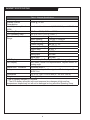
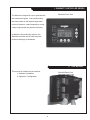
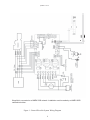
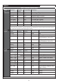
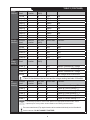
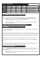
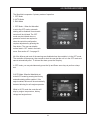
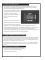
OWN-GEN WaveNet Digital Monitoring System General Installation and User Manual Marine Generators | Marine Diesel Engines | Land-Based Generators Northern Lights 4420 14th Avenue N.W. Seattle, WA 98107 Tel: (206) 789-3880 Fax: (206) 782-5455 Copyright ©2012 Northern Lights, Inc. All rights reserved. Northern Lights™, and the Northern Lights logo are trademarks of Northern Lights, Inc. Printed in U.S.A. PART NO.: OWN-GEN 1/12 USER MANUAL for WaveNet Generator Set Controllers Table of Contents WaveNet Specifications ..................................... 2 GROUP 1 - WAVENET CONTROLLER SERIES 4.7.3 Event History Log ........................... 16 - 17 1.1 This Manual........................................... 3 4.8 WaveNet LED Status Indicators.......... 18 GROUP 2 - RECEIVING, HANDLING & STORAGE ..4 4.9 Lamp Indication Meanings ............ 18 -19 GROUP 3 - INSTALLATION & WIRING 4.10 Warnings & Failures ................... 19 - 20 3.1 Safety Information ................................. 5 4.11 Genset Online ................................... 20 3.2 12/24 VDC System Operation............... 5 GROUP 5 - ADVANCED SETUP ..........................20 3.2.1 Relays ................................................ 6 GROUP 6 RECOMMENDED MAINTENANCE ..... 20 3.2.2 Relay Fuses ....................................... 6 GROUP 7 - WAVENET REMOTE PANEL 3.3 WaveNet Terminals ........................ 6 - 10 7.1 Remote Unit Settings ................................ 21 3.3.1 Current Transformer Wiring Note ..... 10 7.2 On-Line Genset Status Mode............... 21 - 22 7.2.1 Genset Controller’s Name................ 22 GROUP 4 - OPERATION & BASIC USER CONFIGURATION 7.2.2 State ................................................. 22 4.1 Power-Up ............................................ 10 7.2.3 Status Mark ...................................... 22 4.2 Controller Alarming ............................. 10 7.3 On-Line Genset Parameter Mode 22 - 23 4.3 Controller States .......................... 11 - 12 GROUP 8 - APPENDEX A: ACCESSORY LIST 4.3.1 Locking the WaveNet Screen in Run Mode . 12 8.1 WaveNet Controller Harness - Accessories .... 23 4.4 WaveNet Start / Stop Behavior .... 12 - 13 8.2 CT’s (Current Transformers) ............... 24 4.5 Controller Sleep .................................. 13 8.3 WaveNet Replaceable 12/24 VDC Relays .. 24 4.6 WaveNet Menu System Operation...... 13 8.4 WaveNet Fusing.................................. 24 4.7 Basic Menu ......................................... 14 GROUP 9 - APPENDIX B: ADDITIONAL DRAWINGS .26 4.7.1 Clock Setup ...................................... 14 4.7.2 Basic Setup ...................................... 15 Proprietary Information This publication is the sole property of Northern Lights, Inc. It may not be reproduced in whole or part without the expressed written permission of Northern Lights, Inc. © Northern Lights, Inc. 2012. All rights reserved. Litho U.S.A. Publication number: OWN-GEN 8/12 1 WAVENET SPECIFICATIONS Table 1: Wavenet Specifications VDC Rating Standby Current Consumption Load Equivalency Number (LEN) Operating Temp LCD Operating Temp. ** Function Range LCD Display LED Display 12/24 VDC 50 mA @ 12 VDC WaveNet: 1 / WaveNet remote:2(NMEA 2000® Spec. : 1 LEN=50mA) -40oC to +85oC (-40oF to +185oF) -20oC to +70oC (-4oF to +158oF) Function Range Speed Sensing 0-300vac, 0-3600rpm Voltage Sensing Max 700vac, +/- 1% Current Sensing * Max 5A, +/- 2% Frequency Sensing 1 - 100 HZ Engine Temp 10-265 oF Oil Pressure 0-90 PSI Analog Input 7mA Max Digital Input 7mA Max 128 x 60 Graphic Display, Backlit, 60o viewing angle Red, Green, Yellow LED representation, Daytime visible, 60o viewing angle NMEA 2000® Connector Relays DeviceNet Micro-C replaceable relays for Run signal and Preheat signal, 12 or 24VDC Coil Dimensions W x H x D: 139 x 113 x 65 mm (5.7 x 4.45 x 2.56 in.) Weight 0.45 kg (1.0 lb) * Use of industry standard CT required. ** The LCD display will exhibit color and response time changes at high and low temperatures respectively but will not be damaged as long as within Operating Temp. OWN-GEN 01/12 2 1. WAVENET CONTROLLER SERIES WaveNet Front View The WaveNet is designed for use on generator sets with mechanical engines. It can monitor analog data from senders on the engine and generator such as oil pressure, coolant temperature, current, voltage, engine speed and generator frequency. In addition to the monitoring features, the WaveNet controller can be used to provide protective warnings or shutdowns. 1.1 THIS MANUAL This manual is divided into two sections: 1. Hardware installation 2. Operation / Configuration WaveNet Back View OWN-GEN 01/12 3 2. RECEIVING, HANDLING & STORAGE Receiving: Every effort is made to ensure that your WaveNet gen-set controller arrives at its destination undamaged and ready for installation. The packaging is designed to protect the WaveNet internal components as well as the enclosure. Care should be taken to protect the equipment from impact at all times. Do not remove the protective packaging until the equipment is at the installation site and ready to be installed. When the WaveNet reaches its destination, the customer should inspect the shipping box and controller for any signs of damage that may have occurred during transportation. Any damage should be reported to a Northern Lights representative after a thorough inspection has been completed. A shipping label affixed to the shipping box includes a variety of product and shipping information, such as items and Customer numbers. Make certain that this information matches your order .... information. Each WaveNet controller is packaged in its own box. Do not discard the packing material until the controller is ready for installation. Handling: As previously mentioned, each WaveNet gen-set controller is packaged in its own individual box. Protect the equipment from impact at all times and do not carelessly stack. Once the controller is at the installation site and ready to be installed, the packaging material may be removed. Storage: Although well packaged, this equipment is not suitable for outdoor storage. WaveNet is to be stored indoors for any period of time, it should be stored with its protective packaging in place. Protect the controller at all times from excessive moisture, dirty conditions, corrosive conditions, and other contaminants. It is strongly recommended that the package-protected equipment be stored in a climate-controlled environment of -20 to 65°C (-4 to 149°F), with a relative humidity of 80% or less. Do not stack other equipment on top of the stored controllers. OWN-GEN 01/12 4 updated 1-17-12 3. WAVENET SERIES INSTALLATION AND WIRING 3.1 SAFETY INFORMATION Generator systems contain high voltage circuits. Working on powered equipment can cause damage to equipment, injury, or death. The following symbols will be used in this document to classify information: Caution: This is used to indicate something that you should take special notice of but that is not normally a threat to safety. Danger: This is used to indicate a potential for injury or death. Danger - High Voltage: This is similar to Danger above but relates specifically to conditions where high voltage is encountered. The following general safety precautions should be headed: 1. The WaveNet may carry high Voltage/Current which can cause serious injury or death. Extreme caution must be exercised when connections are being installed to or from the controller. All wiring connections must be de-energized before any installations are performed. Wiring of the WaveNet should be performed by qualified electricians only. 2. AC power may carry high Voltage/Current which can cause serious injury or death. De-energize all AC power sources before any connections are performed. 3. NEVER energize AC power with AC current sensing connector unplugged. An energized, unplugged connector could result in severe injury or death. Never unplug an energized connector. 4.WaveNet is connected on a NMEA 2000 network. Installation must be made by an NMEA 2000 certified technician. 3.2 WAVENET 12/24VDC SYSTEM OPERATION The WaveNet controller can be placed in either 12V or 24V electrical systems. OWN-GEN 01/12 5 3.2.1 RELAYS The WaveNet controller is designed to operate on 12 or 24 VDC systems. When operating on 12VDC systems the fuel and preheat outputs require 12VDC relays, and 24VDC relays when operating on 24VDC systems. The WaveNet comes preinstalled with the correct relays depending on the product number specified when ordered. Contact Northern Lights if replacement relays are required. Relays for 12 or 24VDC system operation are as follows: • 22-42047 for 12VDC operation • 22-40085 for 24VDC operation 3.2.2 RELAY FUSES CAUTION: needs to be taken when connecting relay outputs to an inductive load. Due to the inductive nature of certain loads (starters, pull coils), initial current draw may be higher than stated in the load specs which could damage the onboard relays. Output relays are protected by onboard 40A fuse protection. Smaller amperage fuses from many automotive stores may be used in place of the higher current 40A. If installing lower amperage fuse protection, be certain that the current draw on each relay does not exceed the fuse current limit. An approved 40A fuse is: LITTLEFUSE – 257040 (32VDC, 40A, auto fast action) 3.3 WAVENET TERMINALS Figure 1 on page 6 shows the location of all terminals on the controller and the numbering of all circuits. Table 2 lists the minimum wire size, maximum current capacity, name, and function of each circuit. The wire gauges given in the table are the minimum recommended only. OWN-GEN 01/12 6 updated 1-17-12 WaveNet is connected on a NMEA 2000 network. Installation must be made by an NMEA 2000 certified technician. Figure 1 - General WaveNet System Wiring Diagram 7 TABLE 2 Table 2: WaveNet Terminal Details Quick Fit Terminals Terminal Wire Size (AWG) 12 12 12 12 12 12 18 18 Current Max* Functions Crank 40A 1 40A Battery + 1 40A Battery Fuel 40A Extra Relay 40A Extra Relay 40A Speed 1 100mA Speed 2 100mA * Total controller current output (max 60A) Crank Output Terminal Positive Battery Terminal Negative Battery Terminal Fuel Output Terminal Pre-Heat Input Terminal Pre-Heat Output Terminal Speed Signal Connection Speed Signal Connection 1 Ensure wire gauge is sufficient: otherwise (especially during cranking) there could be a voltage drop across the cable to the controller from the battery related features of the controller. Analog Inputs Digital Inputs Terminal Detail Ground Input 2 Input 3 Terminal Location 1 2 3 Wire Size (AWG) 18 18 18 Current Max. Function Input 4 4 18 Input 5 Input 6 Input 7 5V out Terminal Detail Input H - GND Input G - GND Input F - GND Input E - GND Input D - BAT Input C - BAT Input B - BAT Input A - BAT Emer. Stop 5 6 7 8 Terminal Location 1 2 3 4 5 6 7 8 9 18 18 18 18 Wire Size (AWG) 18 18 18 18 18 18 18 18 18 10 10 18 7mA N/A N/A Auxiliary Failure1 Option Coolant Level Switch1 N/A N/A N/A N/A Allows Manual Emergency Stop (Open = Active) N/A Ground 11 18 7mA Ground Ground 12 18 7mA Ground 7mA 7mA 7mA N/A N/A Engine Temperature Sender (Low Resistance, Gain of 3) 7mA Oil Pressure Sender (Low Resistance, Gain of 3) 7mA N/A 7mA N/A 7mA N/A 7mA N/A Current Max. Function 7mA 7mA 7mA 7mA 7mA 7mA 7mA 7mA 7mA 1 Ground input to generate logic high. OWN-GEN 01/12 8 TABLE 2 (CONTINUED) Digital Outputs Terminal Detail + V Bat Output A Output B Output C Output D Output E Output F Output G Output H + V Bat RS485 Terminal (Modbus) Detail RS485-A Ground AC Voltage Sensing AC Current Sensing Terminal Location 1 2 3 4 5 6 7 8 9 10 Terminal Location 1 2 Wire Size (AWG) 18 18 18 18 18 18 18 18 18 18 Wire Size (AWG) 18 18 Current Max. Function 1.5A 200mA 200mA 200mA 200mA 200mA 200mA 200mA 200mA 1.5A Current Max. N/A N/A N/A N/A N/A N/A N/A N/A N/A N/A Function 7mA 7mA N/A N/A RS485-B 3 18 7mA N/A RS485-A 4 18 7mA N/A Ground 5 18 7mA N/A RS485-B 6 18 7mA N/A Terminal Detail Terminal Location Wire Size (AWG) Current Max. Function Phase A * 1 18 7mA Monitor Generated AC Voltage Phase B * 2 18 7mA Monitor Generated AC Voltage Phase C * 3 18 7mA Monitor Generated AC Voltage Neutral 4 18 7mA AC Voltage Neutral connection * Place 1A fuse between the hot lines and the voltage sensing terminals of WaveNet. Terminal Terminal Wire Size Current Max. Function Detail Location (AWG) Phase A 1 18 5A Phase A Current Sensing CT Phase B Phase C 2 3 18 18 5A 5A Phase B Current Sensing CT Phase C Current Sensing CT - Phase A 4 18 5A Phase A Current Sensing CT + Phase B 5 18 5A Phase B Current Sensing CT + Phase C 6 18 5A Phase C Current Sensing CT + It is extremely important to connect each phase to the appropriate terminal location. Never misphase inputs. Always match terminal details to the matching terminal location The current transformers (CTs) negative leads must be terminated individually into the WaveNet AC Current connector. DO NOT CONNECT TOGETHER. OWN-GEN 01/12 9 updated 1-17-12 TABLE 2 (CONTINUED) NMEA 2000® Terminal Detail NET-H NET-S NET-L NET-C Terminal Location 1 2 3 4 Wire Size (AWG) 22 22 22 22 Current Max. 7mA 7mA 7mA 7mA Function NMEA2000® Data High NMEA2000® Bus Power + NMEA2000® Data Low NMEA2000® Bus Ground 3.3.1 CURRENT TRANSFORMER (CT) WIRING NOTE The current transformers (CTs) negative leads must be terminated individually into the WaveNet AC Current connector. Do not tie the negative leads together to a common ... neutral or ground. The negative lead of the CT is usually black. WaveNet is connected on a NMEA 2000 network. Installation must be made by an NMEA 2000 certified technician. 4 WAVENET OPERATION & BASIC USER CONFIGURATION 4.1 POWER-UP The controller will display the firmware and hardware version on the screen and flash the indicator lamps on the side of the controller. The controller will then enter the OFF mode. By default, it is possible to manually start the generator in the OFF mode. The user can disable manual start in OFF mode in the basic menu (in which case the WaveNet must be in the AUTO mode to manually start the generator). See section 4.7.2 on page 15. Pressing the Info key will cause the controller to enter the AUTO mode. From this mode, the user can put the controller into RUN mode (i.e. start the generator) manually or from a WaveNet Remote Panel. The controller has the ability to remember whether it was in the OFF or AUTO mode the last time it was powered up and will reenter that mode when it is repowered. 4.2 CONTROLLER ALARMING If the emergency stop input of the digital input terminal is not connected to ground the controller will alarm and display “Emergency Stop” when powered. Emergency Stop also forces the controller to the OFF mode. To prevent this ground the emergency stop input (pin 9) to ground (pin 12) on the digital input terminal. See Figure 1 on page 6. OWN-GEN 01/12 10 4.3 CONTROLLER STATES The WaveNet incorporates 3 primary modes of operation: 1. OFF Mode 2. AUTO Mode 3. RUN Mode 1. OFF Mode – When the WaveNet is set to the OFF mode, automatic starting will be disabled. No automatic controls will be initiated. The OFF mode may be initiated when no generator controls are required or when the controller configuration requires adjustment by pressing the Stop button. The user can disable manual start in OFF mode in the basic menu. See section 4.7.2 on page 15. All of the failures and most of the warnings are disabled when the controller is in the OFF mode. The controller will beep every few seconds to alert the user that the unit is in the OFF mode and cannot automatically start. To silence this alarm, press the Stop key. In OFF mode, you may simultaneously press the Up and Down arrow keys to perform a lamp test. 2. AUTO Mode - When the WaveNet is set to the AUTO mode by pressing the Info key, automatic starting will be enabled. If the engine is started, failures will be automatically detected allowing for safe engine operation. While in AUTO mode the controller will display engine temperature, battery voltage and engine hours. OWN-GEN 01/12 11 4.3 CONTROLLER STATES (CONT’D) 3. RUN Mode – The controller starts the engine/generator and enters the RUN mode when it receives the command from a WaveNet Remote Panel or the user manually starts the engine/generator by pressing the Start key. The controller will automatically shut the engine/generator down and re-enter the auto mode if it initiated an engine/ generator start. When the controller is in the OFF mode automatic starting is disabled. When the controller is in the RUN mode, generator parameters will be displayed on the screen to allow the user to monitor the engine status. These include engine speed, generator voltage and current, and engine temperature as well as others. The parameters are displayed in groups and the screen scrolls between the various groups. The Page Roll Display menu option controls how long each parameter group is displayed on the screen before moving on to the next group. See Table 5 on page 15 for more information. 4.3.1 LOCKING THE WAVENET SCREEN WHILE IN RUN MODE When in the RUN mode the WaveNet LCD screen can be locked to display a particular parameter group. To do this press the Up and Down keys to scroll to the parameter group you wish to view and then press the Enter key to lock the screen. You will see a lock symbol displayed on the top right hand side of the display just under the date and time. To unlock the screen press Enter again or use the arrow keys to scroll to a different parameter group which causes the lock symbol to disappear. The screen will automatically unlock after 10 minutes. 4.4 WAVENET START / STOP BEHAVIOR There are two ways to start the generator (start conditions): 1. Start key – Located on the WaveNet front panel. 2. Remote WaveNet panel Start key OWN-GEN 01/12 12 4.4 WAVENET START / STOP BEHAVIOR (CONT’D) When the controller is in the AUTO mode the two manual start conditions above can be used to start the generator. When the controller is in the RUN mode it will display the reason for start on the screen (NMEA 2000 Run, Manual Run). Stopping the Generator The Stop key on the front panel can be used to place the WaveNet in OFF regardless of the start condition. 4.5 CONTROLLER SLEEP The controller has a low power sleep mode that it can enter when in the OFF or AUTO states. In this state the LCD screen backlighting is turned off. The time it takes to enter the sleep mode is configurable in the menu. It is recommended that the Sleep Delay is set as short as possible to prolong the life of the backlighting and to reduce battery consumption. The backlight display will illuminate automatically when a key is pressed. A key press will only cause the controller to exit the sleep mode. The key must be pressed again to perform its normal function. 4.6 WAVENET MENU SYSTEM OPERATION The WaveNet incorporates a menu system to allow the end user to adjust basic settings. In the OFF state press Enter to access the WaveNet menu system. This is called the Basic Menu. The following keys perform the menu navigation: 1. Scroll up using the Up key 2. Scroll down using the Down key 3. Enter menus by pressing the Enter key. Each menu has a “Back” selection. To go back to the previous menu scroll up to the Back selection and press the Enter key. When in the basic menu you can go back to the OFF mode by pressing the Stop key. OWN-GEN 01/12 13 4.7 BASIC MENU When you press the Enter key in the OFF mode you will enter the Basic Menu which includes the Clock Setup, Basic Setup, Advanced Setup, and Failure History submenus. 1. Clock Setup 2. Basic Setup 3. Advanced Setup 4. Failure History Table 3: Basic Menu Layout Basic Menu: Clock Setup Basic Setup Year, Month, Date, Day, Hour, Minute, 12/24 Contrast Adj, Page Roll Delay, State Roll Delay, Sleep Delay, Maintenance, Not In Auto, Off Mode Start Failure History 4.7.1 CLOCK SETUP The Clock Setup menu will allow you to set the clock. The clock is important if you are planning to use the Event Log (records all failures and warnings and when they occurred). Menu Year Month Date Day Hour Minute 12/24 Table 4 – Clock Setup Menu SELECTION AND RANGE 2000-2099 January - December 01-31 Monday - Sunday 00 - 23 00 - 59 12 Hours - 24 Hours The WaveNet internal clock information can remain “in memory” for approximately 2 weeks when no DC power is supplied to the controller. Two week memory storage is available in a completely charged controller clock. DC power is required to be supplied continually to the WaveNet for approximately 1 hour to allow a complete clock charge. OWN-GEN 01/12 14 4.7.2 BASIC SETUP The Basic Setup menu will allow the user to customize the basic features of the WaveNet to their preference. The Contrast Adjustment allows the user to adjust the contrast of the LCD. The Page Roll Delay controls how long each group of parameters are displayed in the RUN state (i.e. when the engine/generator is running) before displaying the next set of parameters. The second line of the WaveNet LCD screen is usually dedicated to displaying warnings, and events. The State Roll Delay determines how long the warning or event message is displayed before moving on to the next message. Setting the State Roll Delay to a larger value may cause some warning or event messages to not be displayed if the event or warning is of a short duration. The Sleep Delay determines how long to wait after the last key press before turning off the LCD backlighting. The Sleep Delay also controls the automatic exit from the menu system. First the controller exits to the Basic Menu after the first sleep delay, exits to the OFF state after the second sleep delay, and finally goes into sleep mode after the third sleep delay. The Sleep Delay does not work in the RUN Mode or during cranking. The controller can be made to NOT sound the alarm when the controller is not in the AUTO mode. This is controlled by the Not In Auto setting. The OFF Mode Start setting can be set to Enable to allow a manual start from the OFF mode. Otherwise a manual run can only be performed when the controller is in the AUTO mode. Menu Contrast Adjust Page Roll Delay State Roll Delay Sleep Delay Maintenance Not In Auto OFF Mode Start Table 5 – Basic Setup Menu SELECTION AND RANGE 5-95 % 1-10 s 1-10 (1 is shortest delay, 10 is longest) 10-600s. Shorter is ideal to extend the backlighting life. Read only. Displays the amount of hours until next service if this feature is enabled. If service is overdue the hours become negative. Disable Beep, Enable Beep Disable, Enable OWN-GEN 01/12 15 4.7.3 EVENT HISTORY LOG The WaveNet incorporates an event history logging system. When engine failures or events occur, an entry is created in the WaveNet Event History Log. See Table 6 – Event Log Entries below for the possible events that are stored. A total of 70 entries can be recorded. Entries may be viewed simply by scrolling up or down using the Up and Down keys. In addition to the entry reason information, the associated date and time of the entry will be displayed. The 70 entries are subdivided into a maximum of 30 events and 40 failures. This prevents one type from flushing the other types from the log. Simply scroll through the Failure History Log by pressing the Up or Down arrow keys located on the WaveNet. The event history log can store up to 30 event and 40 failures entries. If these are exceeded the oldest entry is replaced with the newest entry. The events and failures are displayed together in the log in reverse chronological order (i.e. newest entry first). EVENT LOG ENTRIES Table 6: Event Log Entries An “*” beside the Event Entry indicates the Event is a WaveNet event. All other events are failures. (See page section 4.10 on page 19) Event Entry ADC SWITCH FAILURE ADE READ FAILURE ADE WRITE FAIL AUTO ENABLE * AUXILIARY FAIL EEPROM FAILURE EMERGENCY STOP EPS LOADS ERROR HIGH BATTERY HIGH ENGINE TEMP Description These are internal WaveNet failures. Try power cycle the WaveNet. If failure occurs repeatedly the unit could be defective. Info button on the front face of controller pressed. WaveNet placed in AUTO mode. The Auxiliary Fail digital input has been triggered. This is an internal WaveNet failure. Try to power cycle the WaveNet. If the failure occurs repeatedly the unit could be defective. The emergency stop input (located on the digital input terminal) has been activated. AC current sensing indicating that the generator is not running. This could indicate something is wrong with the WaveNet. (See section 4.11 on page 20.) Failure occurred due to high battery voltage. Failure occurred due to high engine coolant temperature. OWN-GEN 01/12 16 EVENT LOG ENTRIES Event Entry INITIALIZING * KEY BOARD FAILURE LOCKED ROTOR LOSS OF ECM COMM LOW BATTERY LOW COOLANT (LEVEL) LOW OIL PRESSURE MANUAL START * MANUAL STOP * OFF ENABLE * OPEN ENG TEMP OPEN ENGINE TEMP OPEN OIL PRES OVER CRANK OVER CURRENT OVER FREQUENCY OVER SPEED OVER VOLTAGE POWER ON * SHORT ENG TEMP SHORT ENGINE TEMP SHORT OIL PRES TLE6230 FAILURE UNDER FREQUENCY UNDER SPEED UNDER VOLTAGE Description EEPROM is being loaded with factory defaults. This occurs on first power up. This is an internal WaveNet failure. Try to power cycle the WaveNet. If failure occurs repeatedly, the unit could be defective. Cranking attempt failed on locked motor. NMEA2000 messages required by the WaveNet have not been received. The generator has shut down. Low battery voltage failure. Low coolant level failure. Low oil pressure failure. Generator started manually from the front panel Start key Generator stopped manually from the front panel Stop button Front panel Stop key pressed to disable automatic starting. Analog sender always reads the maximum voltage. Could indicate that the sender is not connected to the analog input. (i.e. broken wire) The engine did not start after multiple attempts. Over current failure. Generator frequency over the failure threshold. Generator RPM too high. Generator voltage high. WaveNet was powered up from unpowered state. Analog sender reads zero volts or close to zero. This could be caused by a shorted sender. These are internal WaveNet failures. Try power cycle int WaveNet. If the failure occurs repeatedly the unit could be defective. The generator frequency is too low. The engine speed is too low. The generator voltage is too low. OWN-GEN 01/12 17 4.8 WAVENET LED STATUS INDICATORS Some industry standard failures, warnings, and events on the WaveNet are indicated by a series of LEDs on the left side of the controller. Specific LED indicators will be illuminated depending upon the condition of the controller. The WaveNet LED indicators allow a quick check of the controller’s condition. The WaveNet displays multi color LED’s for specific condition representation. Red - Represents Failure Conditions An LED test may be performed by the user for illumination of all controller LED’s. The LED test may be performed by simultaneously pressing the Up key and the Down key on the WaveNet. Yellow - Represents Warning Conditions Green - Represents Normal/Active Conditions 4.9 LAMP INDICATION MEANINGS LED Description Over Crank High Engine Temp Low Oil Press LED color Table 7: WaveNet Lamp Indication Meanings LED Status Indication Red Solid Red Yellow Solid Yellow Red Solid Red Yellow Solid Yellow Red Solid Red Yellow Solid Yellow A solid red illuminated LED represents an Over Crank condition on the final crank attempt. This is a Failure. A solid yellow illuminated LED represents an Over Crank Warning condition when there are crank attempts still remaining. A solid red illuminated LED represents a High engine Temp Failure condition A solid yellow illuminated LED represents a High engine Temp Warning Condition A solid red illuminated LED represents a Low Oil Pressure Failure condition. A solid yellow illuminated LED represents a Low Oil Pressure Warning condition. OWN-GEN 01/12 18 4.9 LAMP INDICATION MEANINGS (CONT’D) LED Description Over Speed Battery Status Table 7: WaveNet Lamp Indication Meanings (cont’d) LED color LED Status Indication Red Solid Red Yellow Solid Yellow Solid Green Green Flashing Green A solid red illuminated LED represents an Over Speed Failure condition. A solid yellow illuminated LED represents an Over Speed Warning condition. A solid green illuminated LED represents a normal battery condition. Controller in Auto mode - Waiting to start Yellow Solid Yellow Low Coolant A solid yellow illuminated LED represents a Low Battery condition. A solid red illuminated LED represents a Low Coolant (Temperature and/or Level) failure condition Red Solid Red Yellow Solid Yellow A solid yellow illuminated LED presents a Low Coolant Temperature Warning condition. Green Solid Green A solid green illuminated LED represents an active Pre-Heat condition Green Solid Green A solid green illuminated LED indicates that the generator is supplying load and is operating normally. Red Solid Red Pre-Heat Genset Online A solid red indicated load is detected on the generator when none should be. Failure Red Solid Red See Section 4.11 on page 20 for more information about the EPS Supplying Load. A solid red illuminated LED represents a general Failure condition. 4.10 WARNINGS AND FAILURES The WaveNet incorporates many types of warnings and failures. Warnings and failures can be triggered from a Digital Input, Analog Input, AC Voltage, AC Current, Speed Signal Input, as well as others. When a warning occurs, the second line (the area under the time and date display) of the LCD is used to display the warning text. Also, after the warning is displayed, instructions are displayed showing the user how to silence the warning. When in the AUTO or RUN modes the instructions are to press the Info key and when in the OFF mode press the Stop key. OWN-GEN 01/12 19 updated 1-17-12 4.10 WARNINGS AND FAILURES (CONT’D) When a failure occurs the controller exits the RUN mode and goes to the FAILURE mode and displays the failure message. The alarm will sound and remain on until it is silenced by the user. The Info key can be pressed to silence the alarm. Once the alarm is silenced it can be reset by pressing the Info key and then the Stop key. This returns the controller to the OFF mode. The failure is recorded in the event log accessible from the Basic Menu. 4.11 GENSET ONLINE When the generator is started and load is detected on the generator when the WaveNet is in the RUN mode the “Genset Online” LED on the WaveNet front panel will turn green. This indicates that the generator is supply load as normal. If load is detected on the generator when it is not in the RUN mode (e.g. the WaveNet is cranking, preheating, etc.) the WaveNet terminates starting and enters the FAILURE mode and the “Genset Online” LED on the WaveNet front panel will turn red. The generator is considered loaded when either the AC current is equal to or greater than 5% of full load current. 5. ADVANCED SETUP The WaveNet incorporates an Advanced Setup menu. Only advanced and knowledgeable users should change these parameters. WaveNet is connected on a NMEA 2000 network. Installation must be made by an NMEA 2000 certified technician. 6 RECOMMENDED MAINTENANCE The actions in Table 8 should be performed routinely. WARNING: When performing any WaveNet or Engine maintenance be certain controller is in OFF mode, is isolated from all possible sources of power, and the crank wire is removed from the Controller. Table 8: Recommended Maintenance PROCEDURE ACTION Making the controller safe for inspection Disconnect all possible power sources before and maintenance. controller inspection. Inspect controller mounting location for Inspect mounting location for any safety or fire issues. Inspect for dirt, wiring damage and mechanical damages. possible safety issues. Inspect controller for loose fasteners, Check all hardware including controller wiring, terminals and wiring connections. terminals etc. for any looseness due to vibrations etc. Clean area around controller. Periodically inspect and remove any debris/dirt from within or near the controller. Check for any overheating due to loose Check for any discoloration, melting or blistering connections. of any wiring or connections Perform regular testing of controller Perform regular testing of the controller to check for proper operation. OWN-GEN 01/12 20 7 WAVENET REMOTE PANEL There are 3 main display pages for remote unit: the REMOTE UNIT SETTINGS page, ON-LINE GENSET STATUS page and ON-LINE GENSET PARAMETERS page. When the WaveNet Remote unit powers on, it will go to the ON-LINE GENSET STATUS page. 7.1 REMOTE UNIT SETTINGS Access this mode by pressing the Info key from the ON-LINE GENSET STATUS page. Press Info or hold Stop to return to the ON-LINE GENSET STATUS page. On the REMOTE UNIT SETTINGS page, there are 3 settings menus. The Clock Setup, Basic Setup and Advanced Setup will allow the user to change various WaveNet Remote panel settings. Clock Setup - Allows the user to adjust current real time like year, month, week, day, hour, minute and 24/12 display format. Basic Setup - Allows the user to adjust the LCD display contrast, on-line genset message update speed, parameters page scrolling speed and status page backlight shutdown delay. Advanced Setup - To go into this menu, the user needs to input the password. The default password is 0000. Within Advanced Setup there are 3 sub-menus, Networking, Set Units and Set Password. In Networking, the user can enlist the WaveNet Remote to on-line genset controllers. This will Enable or Disable the WaveNet Remote unit to start and stop a genset. The user can also edit the Genset On-Line Timeout Delay. If the Genset On-Line Timeout Delay elapses for an on-line genset without receiving an update from the local WaveNet panel the remote unit will remove that genset from the list of on-line gensets. (Note: “-----” indicates the lack of an on-line genset controller. The ability to enable or disable selections on these “-----” names is unavailable.) In the Set Unit sub-menu, users can set the WaveNet Remote panel to display the temperature in Fahrenheit or Celsius, and the pressure in KPa or PSI. In Set Password the user can change the Advanced Menu access password, the default password is 0000. 7.2 ON-LINE GENSET STATUS MODE The 3 main line positions display the current available on-line genset controllers. Each line displays the on-line Genset Controller’s Name, State and the Status Mark. On the second line of the display, the relevant message of the selected genset controller, like warning, running detail etc., is shown. OWN-GEN 01/12 21 7.2 ON-LINE GENSET STATUS MODE (CONT’D) Move the cursor between the genset controller names using the Up and Down keys and press the Enter key to switch to the ON-LINE GENSET PARAMETERS mode. (Note: only while the selected genset controller is in the AUTO, RUN or FAIL state.) Also from this page, press the Info key to access the settings menus. 7.2.1 GENSET CONTROLLER’S NAME This is used to distinguish WaveNet controlled gensets on the WaveNet Remote display. A “-----” indicates there is no on-line genset controller for that position. 7.2.2 STATE The state of the genset controller will be one of the following 5 states: “AUTO, RUN, FAIL, OFF or MENU.” AUTO - The local WaveNet panel is in the AUTO mode and the genset can be started from any enlisted WaveNet Remote by pressing the Start key. RUN - The local WaveNet panel is running and the genset can be stopped from any enlisted WaveNet Remote by pressing the Stop key. This state includes some sub-states like “Cranking, Preheat, Running, etc.” The detail sub-state messages will show on the second line of the LCD display. FAIL - The local WaveNet panel has shutdown and is in FAILURE mode. The failure must be cleared at the local WaveNet panel before the generator can be restarted. OFF - The local WaveNet panel is in the OFF state and therefore cannot be started from a WaveNet Remote panel. MENU - The local WaveNet panel is in the menu settings or off sleep state. 7.2.3 STATUS MARK The status mark indicates the on-line genset controller’s control status. The Genset Controller Name with status marked “x” means this genset controller cannot be controlled by this WaveNet Remote panel. The Genset Controller Name with status mark “” means this genset was enabled to start or stop by this WaveNet Remote panel. 7.3 ON-LINE GENSET PARAMETER MODE The ON-LINE GENSET PARAMETER mode has 3 different pages corresponding to the on-line genset controller, the AUTO, RUN and FAIL states. Start and stop functionality is the same in this mode as the ON-LINE GENSET STATUS mode. Press the Info key to return to the ON-LINE GENSET STATUS mode. OWN-GEN 01/12 22 updated 1-17-12 7.3 ON-LINE GENSET PARAMETER MODE AUTO - Displays 4 parameters: the engine temperature, engine hours, battery voltage and local WaveNet Remote unit board temperature. RUN - Displays all selected genset running parameters like engine speed, engine temperature, AC voltage current, etc. The display area will cycle to display the different parameters. Operation here is the same as the local WaveNet panel. FAIL - Displays current active failures that caused the genset shutdown. Note: the remote display will switch automatically according to current selected genset controller state. For example, remote unit is displaying AUTO parameters page, if the selected genset goes into running, the remote unit display will switch to display RUN parameters page. If genset was in shutdown state due to some failure happen or user shutdown, the remote unit will switch back to on-line genset status page. 8 APPENDIX A: ACCESSORY LIST 8.1 WAVENET CONTROLLER HARNESS - ACCESSORIES Figure 2 – WaveNet terminal names and layout. View from rear of controller. The Following Identifies all the wiring harnesses as parts of the WaveNet Controller: Table 9 – WaveNet Wiring Harness Part List Harness Description AC Harness Assembly DC Harness Assembly 673 AC Wire Harness 673 DC Wire Harness WaveNet NMEA Panel Connector Part Number 22-40541 22-40612 22-40575 22-40570 22-40598 (for Remotes, use 22-40597) WaveNet is connected on a NMEA 2000 network. Installation must be made by an NMEA 2000 certified technician. OWN-GEN 01/12 23 8.2 CT’S (CURRENT TRANSFORMERS) Current transformers are required for display of AC current. One CT is required for each phase to be displayed. The wiring for CT’s is as follows: In single phase applications: • Phase A to terminals Phase A* • Phase B to terminals Phase B* In three phase applications: • Phase A to terminals Phase A* • Phase B to terminals Phase B* • Phase C to terminals Phase C* In center tap delta applications: • Phase A to terminals Phase A* • Phase B to terminals Phase B* • Phase C to terminals Phase C* Figure 3 - AC Current sensing conections * White wire assumed positive. Black wire assumed negative. CT Description 75A:5A 100A:5A 150A:5A 200A:5A 250A:5A 300A:5A Table 10 – Current Transformers Part List Part No. 22-40021 22-40022 22-40023 22-40024 22-40221 22-40025 8.3 WAVENET REPLACEABLE 12/24VDC RELAYS The WaveNet controller is designed to operate in either 12 or 24 VDC battery start systems. When operating in 12VDC systems the fuel, crank and extra relays need to be rated 12VDC coil. When operating in 24VDC systems these relays need to be rated 24VDC coil. Table 11 – Relay Part List Relay Description 12VDC SPDT 24VDC SPDT Part No. 22-42047 22-40085 8.4 WAVENET FUSING Output relays are protected by onboard 40A fuse protection. Smaller amperage fuses from many automotive stores may be used in place of the higher current 40A. If installing lower amperage fuse protection be certain that current draw does not exceed the fuse current limit. Table 12 – WaveNet fuse part list. Fuse Description Manufacturer Part No. 40A, 32VDC Auto Fast Action Littlefuse-257040 OWN-GEN 01/12 24 revised 1-20-12 9 APPENDIX D: ADDITIONAL DRAWINGS WaveNet is connected on a NMEA 2000 network. Installation must be made by an NMEA 2000 certified technician. OWN-GEN 08/11 25 THIS PAGE INTENTIONALLY BLANK OWN-GEN 08/11 26 updated 1-17-12 WAVENET INSTALLATION TO SOUND SHIELD WaveNet is connected on a NMEA 2000 network. Installation must be made by an NMEA 2000 certified technician. M673L/TF276D Sound Shield (05-78000) B-9802A OWN-GEN 01/12 27 WAVENET INSTALLATION TO SOUND SHIELD M673L3/LD3/TF276D Sound Shield (05-78010) B-9917 OWN-GEN 01/12 28 C-6773C OWN-GEN 01/12 29 B-9973 (FOAM)/B-9974 (PANEL) B-9728 (FOAM)/B-9729 (PANEL) B-10058 M864W/W3 M944W3 M944W3 M844W3/M844LW3 M864W3 M843NW3 B-10057 M844W2/LW2/W3/LW3 M773LW3 B-10057 M843/JK/NK/NW2/NW3 B-10059 TBD B-9949 B-9948 B-9947 PANEL MODIFICATION DWG CURRENT STYLE SHIELD (w/ BASE PAN) MODEL MODEL PANEL MODIFICATION DWG EARLY STYLE SHIELD (w/ BASE PLATE) C NOTE: PUSH HARNESS LOOM THROUGH STRAIN RELIEF BUSHING, APPROX. 1/2" PROTRUSION FROM END. NOTE: ACTUAL SHIELD PANEL CONFIGURATION AND CUT OUT LOCATION WILL VARY, EXAMPLE SHOWN IS TYPICAL FOR ALL WAVENET COMPONENTS USED. M773/W2/LW2/LW3 C B [3X] 8-32 x 3/4" LONG COUNTERSUNK, STAINLESS FLAT HD MACHINE SCREWS. [4X] 6-32 x 1/2" LONG COUNTERSUNK, STAINLESS OVAL HD MACHINE SCREWS. FACEPLATE B SOUND ENCLOSURE PANEL. (SEE TABLE BELOW FOR MODIFICATION INSTRUCTIONS.) PANEL MOUNT NMEA RECEPTACLE. (INSTALLS FROM INSIDE) B WAVENET MODULE [2X] STRAIN RELIEF BUSHINGS. CONNECTION HARNESS A A [4x] 6-32 x 1/2" LONG PAN HEAD STAINLESS STEEL MACHINE SCREWS. [4X] #6 STAINLESS HELICAL LOCKWASHER [4X] #6 FLATWASHER, USS STAINLESS. MODULE ENCLOSURE COVER MODULE ENCLOSURE B revised 8-4-11 WAVENET INSTALLATION IN SOUND SHIELD PANEL REMOVE FILLER PIECE. STEP 1. 52.7 [2.07] 114.3 [4.50] 8.0 [0.31] 209.9 [8.26] 161.9 [6.38] 146.0 [5.75] 6] [Ø0.1 Ø4.1 OLES 4H 5. DEBURR HOLES, BREAK SHARP EDGES. 4. LOCATE HOLE CENTERS AND CUTOUT CORNERS USING CENTERPUNCH. 3. LAYOUT AREA TO BE CUTOUT USING DIMENSIONS AS SHOWN. DIMENSIONS ARE TAKEN FROM THE OUTER PANEL EDGE. 2. PROTECT POWDERCOATED SURFACE WITH 2" WIDE MASKING TAPE. COVER A LARGE ENOUGH AREA TO PERFORM TASK. M773W3 Sound Shield 51.2 [2.02] 117.3 [4.62] 1. PANEL SURFACE MUST BE CLEAN AND FREE OF OILS AND CONTAMINANTS PRIOR TO ANY MODIFICATION WORK. added 8-4-11 WAVENET INSTALLATION TO SOUND SHIELD B-9947 OWN-GEN 01/12 30 B-10057 OWN-GEN 01/12 31 INTERIOR FACE (SOUND FOAM) 184.0 [7.24] 6. REMOVE FOAM. SOME AREA CLEAN UP WILL BE REQUIRED FOLLOWING STEP 2. DO NOT USE M.E.K. OR SOLVENT TO CLEAN RESIDUE FOAM/GLUE (MAY CONTAMINATE REMAINING GLUED AREAS). GENTLE SCRAPING ACTION OF SAFETY BLADE OR GASKET SCRAPER TOOL IS RECOMMENDED. CLEAN UNTIL RESIDUE IS MINIMAL, AND ALLOWS CONTROL PANEL TO SEAT. 5. WHEN ALL FOUR EDGES ARE DEFINED, APPLY ADDITIONAL DOWN PRESSURE TO CUT THROUGH PVC BARRIER LAYER. 4. MAKE INITIAL CUT SHALLOW, DOWN TO THE FOAM BARRIER. 2. USING A BOX CUTTER WITH FRESH BLADE, MAKE CUT FOLLOWING LINES. USE OF STRAIGHT EDGE TO GUIDE BLADE IS RECOMMENDED. 1. WITH THE INTERIOR (SOUND FOAM) SIDE FACING YOU, LAY OUT THE AREA TO BE REMOVED AS SHOWN WITH DIMENSIONS. THE DIMENSIONS ARE TAKEN FROM THE EDGE OF THE PANEL STIFFENER. STEP 1. 30.8 [1.21] 140.0 [5.51] 245.3 [9.66] PANEL STIFFENER EDGE 57.2 [2.25] 114.3 [4.50] 8.0 [0.31] 279.4 [11.00] 4 HOL ES. 5. DEBURR HOLES, BREAK SHARP EDGES. 4. LOCATE HOLE CENTERS AND CUTOUT CORNERS USING CENTERPUNCH. 3. LAYOUT AREA TO BE CUTOUT USING DIMENSIONS AS SHOWN. DIMENSIONS ARE TAKEN FROM THE OUTER PANEL EDGE. 2. PROTECT POWDERCOATED SURFACE WITH 2" WIDE MASKING TAPE. COVER A LARGE ENOUGH AREA TO PERFORM TASK. 1. PANEL SURFACE MUST BE CLEAN AND FREE OF OILS AND CONTAMINANTS PRIOR TO ANY MODIFICATION WORK. Ø4.0 [Ø0.1 6] EXTERIOR FACE (PANEL) 162.0 [6.38] 146.1 [5.75] 55.5 [2.19] 117.6 [4.63] STEP 2. added 8-4-11 WAVENET INSTALLATION TO SOUND SHIELD M773 / W3 / LW2 / LW3 and M843/ JK / NK / NW2 / NW3 Sound Shield REMOVE FILLER PIECE. 8.0 [0.31] OLE S 162.1 [6.38] 146.1 [5.75] 266.5 [10.49] 5. DEBURR HOLES, BREAK SHARP EDGES. 4. LOCATE HOLE CENTERS AND CUTOUT CORNERS USING CENTERPUNCH. 3. LAYOUT AREA TO BE CUTOUT USING DIMENSIONS AS SHOWN. DIMENSIONS ARE TAKEN FROM THE OUTER PANEL EDGE. 2. PROTECT POWDERCOATED SURFACE WITH 2" WIDE MASKING TAPE. COVER A LARGE ENOUGH AREA TO PERFORM TASK. 1. PANEL SURFACE MUST BE CLEAN AND FREE OF OILS AND CONTAMINANTS PRIOR TO ANY MODIFICATION WORK. 50.9 [2.00] 117.9 [4.64] STEP 1. 52.7 [2.07] 114.3 [4.50] [Ø 32 Ø4 .1 OWN-GEN 01/12 4H B-9948 0.1 6] STEP 2. added 8-4-11 WAVENET INSTALLATION TO SOUND SHIELD M843W3 / NW3 Sound Shield 3.07 [78] (SEE DETAIL AT RIGHT) OUTSIDE EDGE OF PANEL STIFFENERS REMOVE THIS AREA 7.25 [184] B-9973 OWN-GEN 01/12 33 INTERIOR FACE 6. REMOVE FOAM. SOME AREA CLEAN UP WILL BE REQUIRED FOLLOWING STEP 2. DO NOT USE M.E.K. OR SOLVENT TO CLEAN RESIDUE FOAM/GLUE (MAY CONTAMINATE REMAINING GLUED AREAS). GENTLE SCRAPING ACTION OF SAFETY BLADE OR GASKET SCRAPER TOOL IS RECOMMENDED. CLEAN UNTIL RESIDUE IS MINIMAL, AND ALLOWS CONTROL PANEL TO SEAT. 5. WHEN ALL FOUR EDGES ARE DEFINED, APPLY ADDITIONAL DOWN PRESSURE TO CUT THROUGH PVC BARRIER LAYER. 4. MAKE INITIAL CUT SHALLOW, DOWN TO THE FOAM BARRIER. 3. USING A BOX CUTTER WITH FRESH BLADE, MAKE CUT FOLLOWING LINES. USE OF STRAIGHT EDGE TO GUIDE BLADE IS RECOMMENDED. 2. SECURE TEMPLATE TO PANEL SURFACE WITH MASKING TAPE. CHECK AND CONFIRM DIMENSIONS NOTED ON DWG. 1. WITH THE INTERIOR (SOUND FOAM) SIDE FACING YOU, ALIGN THE OUTER EDGE OF THIS DRAWING TO THE CORNER, TOP AND LH SIDE OUTSIDE EDGES OF THE PANEL STIFFENER FRAME. NOTES: 5.50 [140] 3.33 [85] THIS SURFACE added 8-4-11 WAVENET PANEL INSTALLATION: STEP 1 M844L / 844 Sound Shield, RH (Service) Side Aft Panel. 4.38 [111] 4.50 [114] 4.31 [110] 4.63 [117] REMOVE THIS AREA 6.38 [162] 5.75 [146] EDGE OF PANEL (SEE DETAIL BELOW) B-9974 OWN-GEN 01/12 34 EXTERIOR FACE THIS SURFACE Ø0.16 [5/32] 4 HOLES. 4.11 [104] 4.42 [112] M844L / 844 Sound Shield, RH (Service) Side Aft Panel. 6. DEBURR HOLES, BREAK SHARP EDGES. 5. LOCATE HOLE CENTERS AND CUTOUT CORNERS USING CENTERPUNCH. 4. SECURE TEMPLATE TO PANEL SURFACE WITH MASKING TAPE. CHECK AND CONFIRM DIMENSIONS NOTED ON DWG. 3. ALIGN THE OUTER EDGE OF THIS DRAWING WITH UPPER RIGHT HAND CORNER, TOP, & RH SIDE EDGES OF SHIELD PANEL. 2. PROTECT POWDERCOATED SURFACE WITH 2" WIDE MASKING TAPE. COVER A LARGE ENOUGH AREA TO PERFORM TASK. 1. PANEL SURFACE MUST BE CLEAN AND FREE OF OILS AND CONTAMINANTS PRIOR TO ANY MODIFICATION WORK. NOTES: added 8-4-11 DYNAGEN PANEL INSTALLATION: STEP 2 REMOVE FILLER PIECE. 50.3 [1.98] 114.3 [4.50] STEP 1. 8.0 [0.32] 199.0 [7.83] 162.1 [6.38] 146.0 [5.75] 48.5 [1.91] 117.9 [4.64] .16] [Ø0 Ø4.1 HOLES 4 STEP 2. 5. DEBURR HOLES, BREAK SHARP EDGES. 4. LOCATE HOLE CENTERS AND CUTOUT CORNERS USING CENTERPUNCH. 3. LAYOUT AREA TO BE CUTOUT USING DIMENSIONS AS SHOWN. DIMENSIONS ARE TAKEN FROM THE OUTER PANEL EDGE. 2. PROTECT POWDERCOATED SURFACE WITH 2" WIDE MASKING TAPE. COVER A LARGE ENOUGH AREA TO PERFORM TASK. 1. PANEL SURFACE MUST BE CLEAN AND FREE OF OILS AND CONTAMINANTS PRIOR TO ANY MODIFICATION WORK. added 8-4-11 WAVENET INSTALLATION TO SOUND SHIELD M844W3 / LW3 Sound Shield B-9949 OWN-GEN 01/12 35 2.19 7.25 REMOVE THIS AREA (SEE DETAIL AT RIGHT) EDGE OF PANEL BOX RISER 5.50 3.19 OWN-GEN 01/12 36 6. REMOVE FOAM. SOME AREA CLEAN UP WILL BE REQUIRED FOLLOWING STEP 2. DO NOT USE M.E.K. OR SOLVENT TO CLEAN RESIDUE FOAM/GLUE (MAY CONTAMINATE REMAINING GLUED AREAS). GENTLE SCRAPING ACTION OF SAFETY BLADE OR GASKET SCRAPER TOOL IS RECOMMENDED. CLEAN UNTIL RESIDUE IS MINIMAL, AND ALLOWS 5. WHEN ALL FOUR EDGES ARE DEFINED, APPLY ADDITIONAL DOWN PRESSURE TO CUT THROUGH PVC BARRIER LAYER. 4. MAKE INITIAL CUT SHALLOW, DOWN TO THE FOAM BARRIER. 3. USING A BOX CUTTER WITH FRESH BLADE, MAKE CUT FOLLOWING LINES. USE OF STRAIGHT EDGE TO GUIDE BLADE IS RECOMMENDED. 2. SECURE TEMPLATE TO PANEL SURFACE WITH MASKING TAPE. CHECK AND CONFIRM DIMENSIONS NOTED ON DWG. 1. WITH THE INTERIOR (SOUND FOAM) SIDE FACING YOU, ALIGN THE OUTER EDGE OF THIS DRAWING TO THE CORNER, TOP AND LH SIDE EDGES OF THE PANEL BOX RISER. NOTES: INTERIOR FACE THIS SURFACE revised 8-2-11 WAVENET PANEL INSTALLATION STEP 1 M864W3 / M944T Sound Shield B-9728A 6. DEBURR HOLES, BREAK SHARP EDGES. 5. LOCATE HOLE CENTERS AND CUTOUT CORNERS USING CENTERPUNCH. 4. SECURE TEMPLATE TO PANEL SURFACE WITH MASKING TAPE. CHECK AND CONFIRM DIMENSIONS NOTED ON DWG. 3. ALIGN THE OUTER EDGE OF THIS DRAWING WITH UPPER RIGHT HAND CORNER, TOP, & RH SIDE EDGES OF SHIELD PANEL. 2. PROTECT POWDERCOATED SURFACE WITH 2" WIDE MASKING TAPE. COVER A LARGE ENOUGH AREA TO PERFORM TASK. 1. PANEL SURFACE MUST BE CLEAN AND FREE OF OILS AND CONTAMINANTS PRIOR TO ANY MODIFICATION WORK. NOTES: 4.63 4.31 4.50 4.38 REMOVE THIS AREA 6.38 5.75 EDGE OF PANEL (SEE DETAIL BELOW) OWN-GEN 01/12 37 EXTERIOR FACE THIS SURFACE Ø0.16 [5/32] 4 HOLES. 3.31 3.63 revised 8-2-11 WAVENET PANEL INSTALLATION: STEP 2 M864W3 / M944T Sound Shield B-9729A 30.8 [1.21] 140.0 [5.51] OWN-GEN 01/12 38 6. REMOVE FOAM. SOME AREA CLEAN UP WILL BE REQUIRED FOLLOWING STEP 2. DO NOT USE M.E.K. OR SOLVENT TO CLEAN RESIDUE FOAM/GLUE (MAY CONTAMINATE REMAINING GLUED AREAS). GENTLE SCRAPING ACTION OF SAFETY BLADE OR GASKET SCRAPER TOOL IS RECOMMENDED. CLEAN UNTIL RESIDUE IS MINIMAL, AND ALLOWS CONTROL PANEL TO SEAT. 5. WHEN ALL FOUR EDGES ARE DEFINED, APPLY ADDITIONAL DOWN PRESSURE TO CUT THROUGH PVC BARRIER LAYER. 4. MAKE INITIAL CUT SHALLOW, DOWN TO THE FOAM BARRIER. 2. USING A BOX CUTTER WITH FRESH BLADE, MAKE CUT FOLLOWING LINES. USE OF STRAIGHT EDGE TO GUIDE BLADE IS RECOMMENDED. 179.9 [7.08] 8.0 [0.31] 190.9 [7.52] EXTERIOR FACE (PANEL) 162.0 [6.38] 146.1 [5.75] [Ø0.1 6] 4 H OLES . 5. DEBURR HOLES, BREAK SHARP EDGES. 4. LOCATE HOLE CENTERS AND CUTOUT CORNERS USING CENTERPUNCH. 3. LAYOUT AREA TO BE CUTOUT USING DIMENSIONS AS SHOWN. DIMENSIONS ARE TAKEN FROM THE OUTER PANEL EDGE. 2. PROTECT POWDERCOATED SURFACE WITH 2" WIDE MASKING TAPE. COVER A LARGE ENOUGH AREA TO PERFORM TASK. 1. PANEL SURFACE MUST BE CLEAN AND FREE OF OILS AND CONTAMINANTS PRIOR TO ANY MODIFICATION WORK. STEP 2. Ø4.0 M944W3 Sound Shield 1. WITH THE INTERIOR (SOUND FOAM) SIDE FACING YOU, LAY OUT THE AREA TO BE REMOVED AS SHOWN WITH DIMENSIONS. THE DIMENSIONS ARE TAKEN FROM THE EDGE OF THE PANEL STIFFENER. STEP 1. INTERIOR FACE (SOUND FOAM) 184.0 [7.24] 57.4 [2.26] 114.3 [4.50] B-10058 55.7 [2.19] 117.6 [4.63] PANEL STIFFENER EDGE added 8-4-11 WAVENET INSTALLATION TO SOUND SHIELD INTERIOR FACE (FOAM) REMOVE FILLER PIECE. 114.3 [4.50] 8.0 [.31] 76.2 [3.00] ] 16 Ø. ES [ .0 OL Ø4 4 H B-10059 OWN-GEN 01/12 39 EXTERIOR FACE (PANEL) 162 [6.38] 146 [5.75] 40.8 [1.61] 117.6 [4.63] STEP 1. 5. DEBURR HOLES, BREAK SHARP EDGES. 4. LOCATE HOLE CENTERS AND CUTOUT CORNERS USING CENTERPUNCH. 3. LAYOUT AREA TO BE CUTOUT USING DIMENSIONS AS SHOWN. DIMENSIONS ARE TAKEN FROM THE OUTER PANEL EDGE. 2. PROTECT POWDERCOATED SURFACE WITH 2" WIDE MASKING TAPE. COVER A LARGE ENOUGH AREA TO PERFORM TASK. 1. PANEL SURFACE MUST BE CLEAN AND FREE OF OILS AND CONTAMINANTS PRIOR TO ANY MODIFICATION WORK. STEP 2. added 8-4-11 WAVENET INSTALLATION TO SOUND SHIELD M944W3 Sound Shield 42.4 [1.67] WAVENET REMOTE PANEL INSTALLATION DIMENSIONS B-9829 OWN-GEN 01/12 40 4420 14th Ave. NW., Seattle WA 98107 Tel: (206) 789-3880 • 1-800-762-0165 • Fax: (206) 782-5455 Northern Lights and Lugger are registered trademarks of Northern Lights, Inc. www.northern-lights.com © 2012 All rights reserved. Litho USA.