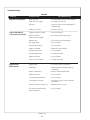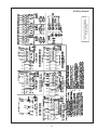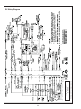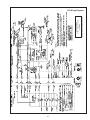
1
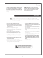
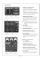
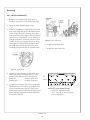
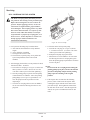
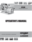
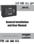
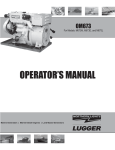
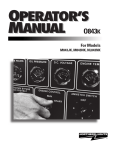
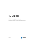
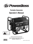
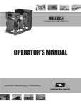
OM944T For Models: M944T and M38CR2 OPERATOR’S MANUAL Marine Generators | Marine Diesel Engines | Land-Based Generators — CALIFORNIA — Proposition 65 Warning: Diesel engine exhaust and some of its constituents are known to the State of California to cause cancer, birth defects, and other reproductive harm. Northern Lights 4420 14th Avenue N.W. Seattle, WA 98107 Tel: (206) 789-3880 Fax: (206) 782-5455 Copyright ©2008 Alaska Diesel Electric, Inc. All rights reserved. Northern Lights™, and the Northern Lights logo are trademarks of Alaska Diesel Electric, Inc. Printed in U.S.A. PART NO.: OM944T 2/11 OPERATOR'S MANUAL for Northern Lights® M944T and M38CR2 Diesel Generator Sets Read this operator's manual thoroughly before starting to operate your equipment. This manual contains information you will need to run and service your new unit. Table of Contents SERVICING (Continued) V-Belts ............................................................. 15 Valve Clearances .............................................. 16 Fuels - General ................................................. 17 Fuel Filters ....................................................... 17 Bleeding the Fuel System ................................ 18 Injector Service ................................................ 19 Injection Pump ................................................. 20 Turbocharger ................................................... 21 Cooling System ............................................... 21 Heat Exchanger ................................................ 22 Raw Water Pump ............................................. 22 Zinc Electrodes ................................................ 22 Electrical System - General ............................. 23 Booster Batteries .............................................. 23 Battery Care ..................................................... 24 Winterizing / Out-of-Service ........................... 24 INTRODUCTION ....................................................2 Model Numbers ..................................................2 Serial Numbers ...................................................2 WARRANTY ............................................................3 SAFETY RULES .....................................................3 COMPONENT LOCATIONS M944T Generator Set ..................................4 - 5 M38CR2 Generator Set ...............................6 - 7 CONTROL PANELS Northern Lights Generator Sets .........................8 OPERATING PROCEDURES Break-in Period ...................................................9 Before Starting ....................................................9 Starting ............................................................. 10 Operating ......................................................... 10 Stopping ........................................................... 10 Shutdowns and Alarms .....................................11 Spare Parts ........................................................11 TROUBLESHOOTING Electrical .......................................................... 25 Engine ...................................................... 26 - 28 WIRING DIAGRAMS AC Electrical ................................................... 29 DC Electrical ........................................... 30 - 31 SERVICING SCHEDULE CHART ............ 12 - 13 SERVICING Lubrication - General ....................................... 14 Checking Oil .................................................... 14 Oil Changes ..................................................... 14 Changing Oil Filter .......................................... 15 Air Filter .......................................................... 15 Proprietary Information This publication is the property of Alaska Diesel Electric, Inc. It may not be reproduced in whole or in part without the written permission of Alaska Diesel Electric, Inc. © Alaska Diesel Electric, Inc. All rights reserved. Litho U.S.A. Publication number OM944T 10/08 OM944T 2/11 3 Introduction The servicing of marine engines and generator sets presents unique problems. In many cases, boats cannot be moved to a repair facility. Marine engines cannot be compared to the servicing of automobiles, trucks, or even farm equipment. Failures often occur in remote areas far from competent assistance. Marine engines are taxed far more severely than auto or truck engines; therefore, maintenance schedules must be adhered to more strictly. Failures begin with minor problems that are overlooked and become amplified when not corrected during routine maintenance. As operator, it is your obligation to learn about your equipment and its proper maintenance. This is not a comprehensive technical service manual. Nor will it make the reader into an expert mechanic. Its aim is to aid you in maintaining your unit properly. Unit Identification MODELS INCLUDED This manual covers the operating instructions for: M944T and M38CR2 marine and commercial generator sets, which use the 944 engine block, turbocharged. Model Numbers Model numbers give the unit's application, block model, aspiration, and RPM: T 944 M M - Northern Lights marine generator set + Model number of engine block Bore Cylinders 94 mm 4 M944T = Northern Lights marine diesel generator set with a 944 engine and a LX-E 34E series generator end. M38CR2 = Northern Lights commercial marine diesel generator set with a 944 engine and a Newage series generator end, 38 kW. + T - Turbocharged Serial Numbers Your set has three serial numbers: 1 an engine number stamped on a plate attached to the valve cover, 2 a generator end serial number, and 3 a generator set serial number. NOTE: Always use the generator set serial number when ordering parts or in correspondence. The generator set serial number plate is found on the service side of the generator and resembles the drawing in Figure 1. Figure 1: Generator set serial number plate. OM944T 2/11 4 Warranty A warranty registration certificate is supplied with your set. It entitles the original purchaser of our equipment to a warranty covering material or assembly faults. The extent of coverage is described in the Limited Warranty Statement. We recommend that you study the statement carefully. NOTE: If the warranty is to apply, the servicing instructions outlined in this manual must be followed. If further information is needed, please contact an authorized dealer or the factory. Safety Rules CAUTION: Accident reports show that careless use of engines causes a high percentage of accidents. You can avoid accidents by observing these safety rules. Study these rules carefully and enforce them on the job. • Never leave engine without proper security. • Use caution in handling fuel. Never refuel a hot or running engine. Do not smoke while filling fuel tank or servicing fuel system. • Turn the coolant tank cap slowly to relieve pressure before removing. Add coolant only when the engine is stopped and cool. • Keep your hands, feet, hair and clothing away from power-driven parts. • Mount a fire extinguisher near engine. • Check for any loose electrical connections or faulty wiring. • Always disconnect the battery ground strap before making adjustments. • Engines should be operated only by knowledgeable, qualified personnel. • Operate engines in properly ventilated areas. • Keep trash and other objects away from engine. • Look completely around engine to make sure that everything is clear before starting. • Escaping fluids under pressure can penetrate your skin. Use a piece of cardboard or wood, not your hands, to search for leaks. • Avoid wearing loose clothing without a belt when working around engines. • Do not operate an engine that isn't in proper working order. If an unsafe operating condition is noted, tag the set and control panel so others will also know about the problem. • Do not oil or grease engine while it is running. • Provide first aid kits. • Remove the negative (-) battery terminal cable before servicing electrical components or welding. CAUTION: This symbol is used throughout this book to alert you to possible danger areas. Please take special notice of these sections. OM944T 2/11 5 Updated 2/8/11 M944T Generator Set Component Locations 1 2 4 3 6 7 8 9 19 18 5 10 17 11 12 16 15 14 13 Figure 2: M944T Service Side (Current Baseframe) 1. 2. 3. 4. 5. 6. 7. Expansion Tank Coolant Fill Thermostat Housing Rocker Arm Cover Lube Oil Fill Intake Manifold Fuel Filter 8. 9. 10. 11. 12. 13. 14. Air Cleaner Junction Box Lube Oil Dipstick Oil Filter Vibration Mounts Fuel Manifold Fuel Primer Pump OM944T 2/11 6 15. 16. 17. 18. Injection Pump Lube Oil Drain Raw Water Pump Heat Exchanger Raw Water Drain and Zinc 19. Heat Exchanger Updated 2/8/11 M944T Generator Set Component Locations 21 19 20 22 23 25 24 Figure 3: M944T Non-Service Side (Current Baseframe) 19. 20. 21. 22. 23. Turbocharger Wet Exhaust Elbow Exhaust Manifold Alternator Belt Guard 24. Starter 25. Oil Pan OM944T 2/11 7 M38CR2 Generator Set Component Locations 2 1 4 5 6 7 3 13 12 11 14 10 9 8 Figure 4: M38CR2 Service Side (Representative only - early production) 1. 2. 3. 4. 5. 6. 7. Expansion Tank Coolant Fill Thermostat Housing Fuel Filter Intake Manifold Air Cleaner Junction Box 8. 9. 10. 11. 12. 13. 14. Harness Plug Lube Oil Dipstick Fuel Manifold (optional) Oil Filter Fuel Primer Pump Injection Pump A.C. Coolant Heater (optional) OM944T 2/11 8 M38CR2 Generator Set Component Locations 19 20 21 24 23 22 Figure 5: M38CR2 Non-Service Side (Representative only - early production) 19. 20. 21. 22. 23. Oil Pan 24. Starter Turbocharger Exhaust Manifold Alternator Belt Guard OM944T 2/11 9 Control Panels 1. PREHEAT/ SHUTDOWN BYPASS This switch serves two functions: 1. Preheats air before beginning the starting process. Press switch for 10-20 seconds before attempting startup. 2. Bypasses the safety shutdown feature during the starting process. Keep switch engaged while starting engine, and for 2 to 3 seconds afterwards, allowing oil pressure to build beyond shutdown setpoint. 2. ENGINE CONTROL SWITCH To start the engine, hold this switch in the START position until the engine is running. After the engine starts, release the switch and it will return to RUN position. To stop the engine, hold the switch in the STOP position. Figure 6-A: Series 1-B Generator Control Panel NOTE: The rocker switch is used on Series 1 panels only, and has a light that glows when the set is running. 3. HOUR METER Keeps track of engine running time. 4. OIL PRESSURE GAUGE Shows the oil pressure in the engine lubricating system. 5. WATER TEMPERATURE GAUGE Registers the temperature of the cooling water. 6. D.C. VOLTMETER Figure 6-B: Series 3 Generator Control Panel When the engine is stopped, the voltmeter indicates the condition of the battery. When the engine is running, the voltmeter indicates the voltage output of the alternator. For Series 4 Control Panels only: 7. A.C. VOLTMETER Shows the generator output voltage. 8. FREQUENCY METER (Hertz) The frequency meter indicates alternating current frequency: 60 Hz (1800 rpm) or 50 Hz (1500 rpm). 9. AMMETER/VOLTMETER SELECTOR Used to check the voltage and current of each phase. Return to “Amps Off” position when not monitoring. 10. A.C. AMMETER Shows the generator load on each phase. The phase is selected with the Ammeter Selector switch (#9). Figure 6-C: Series 4 Generator Control Panel OM944T 2/11 10 Operating Procedures BREAK-IN PERIOD BEFORE STARTING 1. The first 100 hours on a new or reconditioned engine are critical to its life and performance. 1. Check the water level by removing the pressure cap from the expansion tank. In order to give the cooling water an opportunity to expand, the level should be about 1 in. (2.5 cm) below the filler cap sealing surface when the engine is cold. 2. Constantly check the engine temperature and oil pressure gauges. 3. Oil consumption is greater during break-in as piston rings take time to seat. CAUTION: Use protective clothing and open the filler cap carefully when the engine is warm to prevent burns. 4. Break-In Oil Changes: Change engine oil and filter at 50 hours. Change oil and filter again at 100 hours (consult Lubricants section for oil recommendation). 2. Check the oil level in the crankcase with the dipstick. The oil level must be between high and low marks on the stick. Never allow the level to go below this area. Always add the same viscosity of oil as is already in the crankcase. Operating Instructions: Maintain at least a 75% load on your generator set for the first 100 hours. If this is not possible, maintain no less than a 50% load to ensure proper seating of the piston rings. Vary the load to help seat the rings. 3. Check the fuel tank level and open any fuel valves on the tank and at the secondary fuel filter. 4. Close the sea-cock, check and clean the sea strainer, and reopen the sea-cock. 5. Place the battery switch in the ON position. NOTE: The battery switch must always be kept ON while the engine is running. If the switch is turned OFF while the engine is running, the battery charging alternator could be damaged. OM944T 2/11 11 Operating Procedures STARTING OPERATING 1. Hold the Shutdown Bypass switch in the ON position. 1. Units with Series 3 and Series 4 Control Panels: check gauges often. Oil pressure must be above 15 PSI. The D.C. voltmeter should read between 11 and 15 volts at 80° F (25° C) ambient temperature. The water temperature gauge must be below 200° F (94° C). Check the A.C. voltage and frequency meters (Series 4 panel). If the gauges deviate from normal levels, shut down the generator set and investigate. 2. While holding the Shutdown Bypass switch in the ON position, push the Engine Control switch to the START position. 3. As soon as the engine starts, release both switches. Do not crank the starter for more than 10 seconds consecutively. If the engine fails to start with the first attempt, be sure that it has stopped completely before re-engaging the starter. 2. Add electrical load. STOPPING NOTE: Excessive cranking of the starter on marine sets equipped with a water lift muffler can cause engine damage. If the engine does not start after 3 consecutive 10-second cranks, remove the impeller from the seawater pump. This will prevent the muffler from filling with water and backfilling the exhaust line and engine. Once the engine starts, shut if off immediately and reinstall the impeller. Restart and check the exhaust overboard outlet for gushes of water. 1. Remove electrical load from the generator set. 2. Run the engine for a two to three minute cool-down period. 3. Move the Engine Control switch to the STOP position. OM944T 2/11 12 Operating Procedures SHUTDOWNS AND ALARMS SPARE PARTS 1. Your unit is fitted with a system to protect it from high water temperature or low oil pressure. a. Generator sets have shutdown systems to stop the engine. They have no warning horns. b. Other alarms and shutdowns are available as optional equipment. 1. ADE recommends that you keep the following spare parts on hand for field service. The parts are available from your local Northern Lights dealer. Some marine models may already have “On-Board Kits,” a handy box that contains the most common parts you will need. NOTE: If your unit is equipped with optional shutdowns and alarms, do not rely on your warning or shutdown system to the exclusion of careful gauge monitoring. Watching your gauges can prevent damage to the unit and dangerous power losses. a. Primary and secondary fuel filter elements b. Oil filters c. Air filter elements d. Alternator belt e. Thermostat and gaskets f. Seawater pump impeller and gaskets g. Glow plugs h. Injector and washer 2. Do the following when your warning or shutdown system is activated: a. Check the temperature gauge. If above 205° F (96° C), shut off the engine immediately. b. Use the Trouble Shooting Guide on page 25 to isolate the cause of the overheat. 2. If your set is operating a long distance from a servicing dealer, add the following: a. b. c. d. CAUTION: Do not remove the water fill cap of an overheated engine. Escaping high temperature steam can cause severe burns. Allow the engine to cool and then remove the cap slowly using protective clothing. c. Make repairs and restart after the temperature gauge registers below 200° F (94° C). d. Watch the temperature gauge regularly and turn off the unit if the temperature rises above 205° F (96° C). Repeat troubleshooting. 3. If shutdown is activated and the temperature gauge shows temperature within normal temperature range: a. Check the engine crankcase oil level. b. If the oil level is low, fill with recommended lubricating oil and restart. Watch the oil pressure gauge carefully and shut off the engine if it does not show a normal reading (20-60 PSI) after a few seconds of operation. c. If the oil level is normal, DO NOT restart the engine. Call your dealer for assistance. OM944T 2/11 13 Complete set of injectors Copper washers for injector change Complete set of glow plugs Fuel lift pump Servicing Schedule Chart The Servicing Schedule Chart below shows the service schedule required for proper maintenance of your generator set. More detailed coverage of each Service Point (SP) is listed on the page noted in the ‘page’ column. DAILY: SP1 SP8 SP16 EVERY 250 HOURS cont.: SP4 Check air cleaner SP14 Check turbocharger SP20 Check zinc electrodes Check oil level in engine Check primary fuel filter Check cooling water level Check sea strainer EVERY 500 HOURS: SP6 Check valve clearances SP9 Change primary fuel filter element SP10 Change secondary fuel filter SP12 Check injectors SP17 Check cooling system SP19 Change impeller SP22 Check state of charge of batteries AFTER FIRST 50 HOURS: SP2/3 Change engine oil and filter SP5 Check V-belt tension SP21 Check electrolyte level in batteries EVERY 50 HOURS: SP5 Check V-belt tension SP21 Check electrolyte level in batteries EVERY 1000 HOURS or as needed: SP4 Change air cleaner SP13 Check fuel injection pump SP18 Check and clean heat exchanger SP24 Inspect starter and alternator AFTER FIRST 100 HOURS: SP2/3 Change engine oil and filter EVERY 250 HOURS: SP2/3 Change engine oil and filter SERVICE POINT PAGE OPERATION DAILY 50 Hours 100 Hours 250 Hours • • • • • • • 500 Hours 2000 Hours ENGINE: SP1 SP2 SP3 SP4 SP5 SP7 12 12 13 13 13 14 Check oil level Change engine oil1, 5 Change lube oil filters1, 5 Check air cleaner1, 3, 4 Check V-belt tension1, 5 Check valve clearances8 • Check primary filter2 Change primary filter element2, 3 Change secondary fuel filter1, 3 Bleed the fuel system3 Check injectors1, 6 Check fuel injection pump3 • • • • FUEL SYSTEM: SP8 SP9 SP10 SP11 SP12 SP13 15 15 15 16 17 18 • • • • TURBOCHARGER: SP14 19 • Check air, oil, & cooling water lines for leakage1 COOLING SYSTEM: SP16 SP17 SP18 SP19 20 20 21 21 Check cooling water level Check and flush cooling system7 Check and clean heat exchanger Change impeller in raw water pump1, 3 SP20 21 Check zinc electrodes3 • • • • • ELECTRICAL SYSTEM: SP21 SP22 SP24 23 23 24 • Check electrolyte level in batteries1, 3 Check condition of batteries with hydrometer1 Inspect alternator and starter3 • • OUT OF SERVICE: SP23 23 Winterizing or out-of-service3 1) Perform maintenance once a year even if hour level has not been reached. 2) Consult manufacturer's maintenance schedule, note on chart. 3) Or Whenever necessary. 4) Change at 1000 hours. 5) After first 50 hours. 6) Fuel inj. valve opening pressure: 11.77 MPa (120 kgf/cm2) 1710 PSI. 7) Or every 2 years. 8) Valve clearance = .25 mm (0.0098”). OM944T 2/11 14 Service Record Service Point OPERATION HOURS/ DATE 50 HOURS SP5 Check V-belt tension SP21 Check electrolyte in batteries 250 HOURS SP2 Change engine oil SP3 Change lubricating oil filters SP4 Check air cleaner SP14 Check turbocharger SP20 Check zinc electrodes EVERY 500 HOURS SP7 Check valve clearances SP8 Change primary filter element SP10 Change secondary fuel filter SP12 Check injectors SP19 Change impeller in seawater pump SP22 Check condition of batteries with hydrometer 1000 HOURS or as required SP13 Check fuel injection pump SP18 Check and clean heat exchanger Service Notes: OM944T 2/11 15 Servicing LUBRICATION - GENERAL SP1. CHECKING OIL LEVEL 1. Use only clean, high quality lubricants stored in clean containers in a protected area. 1. While the engine is stopped, check the oil level in the crankcase with the dipstick daily. The oil level must be between the high and low marks on the stick. Fill with the recommended oil, and fill only to the high mark on the dipstick. Follow the lubrication recommendations in Figure 7. 2. These lubricants are acceptable: a. API Service CD, CE, and CF-4 single viscosity oils. b. API Service CD, CE, and CF-4 multi-viscosity oils. SP2. OIL CHANGES 1. The set is delivered with special break-in oil. Change the engine oil and oil filter after 50 hours of operation. Use Service CC30 weight oil during the first 100 hours. 3. Use the proper weight oil for your average operation temperature. Air Temperature Single Viscosity MultiViscosity Above 32° F (0° C) -10° to 32° F (-23° to 0° C) SAE 30W SAE 15-40W SAE 10W SAE 10-30W 2. Change the oil and filter again at 100 hours using the oil recommended in the above paragraph. After this, change oil and filter every 250 hours. 3. During intermittent cold weather operation, change oil every 100 hours or six weeks, whichever comes first. Figure 7: Lube Oils 4. Change oil at any seasonal change in temperature when a new viscosity of oil is required. 4. Never put additives or flushing oil in crankcase. 5. Change oil when engine is warm but not hot. 6. Dispose of waste oil in an approved manner. 7. Never use a flushing oil. 8. Loosen clamp on oil change tube. Remove cap. Drain oil. Replace cap and tube. 9. Refill engine with recommended oil. 10. Engine capacity with new oil filter is: ....................2.64 gallons (10 liters) OM944T 2/11 16 Servicing SP3. CHANGING LUBE OIL FILTER SP5. V-BELTS 1. Change the lube oil filter every 250 hours. 1. Check the tension and wear on the V-belt after every 50 hours. 2. Use a filter wrench to remove old filter. Dispose of filter in approved manner. 2. Use your thumb to press on the belt at the midpoint between the crankshaft and alternator pulleys. The tension is correct if the belt can be depressed about .39 to .47 in. (10 - 12 mm) with 22 lbs. (10 kg) force. 3. Make sure the gasket from the old filter is removed and discarded. Clean mount face. 4. Spread a thin film of engine oil on the rubber gasket on the new filter and screw it on nipple until gasket meets the sealing surface. 5. Using hands only – no wrench – tighten filter one-half turn farther. Overtightening can do damage to filter housing. 6. Fill engine with recommended oil. Start engine and check for leakage. Stop engine, wait 3 minutes, and check oil level. Add additional oil if necessary. 7. Oil filter part number is: .......................................#24-01201 SP4. AIR CLEANER 1. Visually inspect air cleaner every 250 hours. 2. Take off the hose clamp on the bracket and the hump hose to detach the air cleaner. 3. Make sure the hump hose is clean inside and also that the new filter element is absolutely clean and installed properly. Note: Make absolutely sure no impurities enter the engine while changing the element, and do not run the engine with the air cleaner removed. Do not clean the filter with diesel fuel, solvent, or gasoline. Serious engine damage can result. OM944T 2/11 17 Servicing SP7. VALVE CLEARANCES 1. Readjust valve clearance after first 50 hours of operation. Check valves every 500 hours thereafter. 2. Check the valves when the engine is cold. 3. Rotate the crankshaft in a clockwise direction in the front 1800 to bring each piston to the top dead center on the compression stroke. Top dead center (TDC) is when notch on the pulley aligns with the pointer and the two valves on cylinder No. 1“rock”. Rocking is when the rocker arms (for the two valves on a given cylinder) are moving in opposite directions, one up closing the valve and one down opening the other valve. The moment when the two rocker arms are exactly aligned with each other is when they “rock”. Figure 9: Valve Adjustment 6. Adjust the remaining valves. 7. Replace the rocker arm cover. Figure 8: Timing Mark 4. Measure the valve clearance for each of the valves, with a feeler gauge, in the firing order (1-3-4-2). Standard valve clearances for a cold engine are: Intake (IN)........................0.0098 in. (0.25 mm) Exhaust (EX)....................0.0098 in. (0.25 mm) Front 5. To adjust valve clearance, loosen the lock nut on the adjustment screw. Insert a feeler gauge between the rocker arm and the valve stem cap. Adjust, while measuring the clearance, until the feeler gauge slides with a slight drag. Tighten the lock nut and recheck the clearance (Figure 9). Tightening Cylinder Head Bolts Order 17 bolts total, Tightening Torque: 113 to 123 N•m (11.5 to 12.5 kgf•m) [83.2 to 90.4 lbf•ft] OM944T 2/11 18 Servicing FUELS - GENERAL SP8-10. FUEL FILTER 1. Use only clean, high quality fuels of the following specifications, as defined by ASTM designation D975 for diesel fuels: a. Use grade No. 2 diesel at ambient temperatures above freezing 32° F (0° C). b. Use grade No. 1 at ambient temperatures below freezing. c. International fuel specifications: JIS K2204 ISO-8217-DMA BS 2869 Part 1 Class A1 BS 2869 Part 2 Class A2 1. Your generator set should have a primary fuel filter installed. We recommend the Northern Lights brand of fuel filters. a. Check the primary fuel filter daily as recommended by the filter manufacturer. b. Change the engine mounted filter as often as necessary or every 250 hours. c. Remove the fuel filter with a filter wrench. d. Apply a coating of fuel to the o-ring of the new fuel filter. e. Tighten the new filter by hand, do not use a filter wrench for tightening. f. The filter should be dry. g. Do not add fuel to the fuel filter before installation, as this could cause unfiltered fuel to enter the fuel pump. h. Bleed the air out of the filter. 2. Use fuel having less that 0.2% sulphur of weight (less than 0.05% recommended). 3. The cetane number should be 45 or higher. 4. Particulate contaminate should be 5.0 mg/l (0.00018 oz/U.S. gal) or lower. The fuel filter part number is: .......................24-51201 5. DO NOT use these unsuitable grades of fuel: a. Domestic heating oils, all types. b. Class B engine. c. Class D domestic fuels. d. Class E, F, G or H industrial or marine fuels. e. ASTM-D975-60T No. 4-D and higher number fuels. 6. Storing fuel: a. Keep dirt, scale, water, and other foreign matter out of fuel. b. Avoid storing fuel for long periods of time. c. Fill the fuel tank at the end of each day’s operation. This will reduce condensation. OM944T 2/11 19 Servicing SP11. BLEEDING THE FUEL SYSTEM CAUTION: Escaping diesel fuel under pressure can penetrate skin causing serious personal injury. Before disconnecting lines be sure to relieve all pressure. Before applying pressure, be sure all connections are tight and lines, pipes and hoses aren't damaged. Fuel escaping from a very small hole can be almost invisible. Use a piece of cardboard or wood, rather than hands, to search for suspected leaks. If injured by escaping fuel, see a doctor at once. Serious infection or reaction can develop if proper medical treatment is not administered immediately. Figure 10 Fuel Feed Pump 1. Fuel system air bleeding may be needed when: a. After fuel has been added to a newly installed engine. b. A new fuel filter is installed. c. The engine has run out of fuel. d. The fuel lines, injection pump, or any other fuel system component has been removed and installed. 3. To bleed air at the fuel injection pump: a. Turn the air vent plug (#3 on Figure 10) about 1-1/2 turns to loosen it. (Cover the vent with a cloth to prevent fuel from splashing.) b. Pump the feed pump cap up and down. c. When there are no air bubbles to be seen in the fuel flowing from the air vent plug hole, push down the priming pump cap and turn it clockwise to lock it in place. 2. After changing the fuel filter, air only needs to be bled from the fuel filter. To do this: a. Loosen the air vent plug (#1 on Figure 10) on the fuel filter by about 1-1/2 turns. (Be sure to cover the vent with a cloth to prevent fuel from splashing.) b. Turn the priming pump cap on the fuel feed pump counterclockwise to unlatch it. Move the priming pump plunger (#2 on Figure 10) up and down. To close the pump turn the cap clockwise while depressing it. c. Close the air vent plug when no more air bubbles can be seen in the fuel flowing from the air vent plug hole. NOTE: Do not close the air vent plug before locking the priming pump cap in place, because the internal pressure in the pump will prevent the priming pump cap from returning to the original position. 4. If the engine does not start after this bleeding process, loosen a fuel line at the injector while cranking the engine with the starter motor until pure fuel escapes. Then tighten the connections. Do each line one-at-a-time. After the engine has started, use a piece of cardboard to look for fuel leaks. OM944T 2/11 20 Servicing SP12. INJECTOR SERVICE 1. Injectors should be checked every 500 hours. This check should be made by a Northern Lights dealer or local injection repair station. 3. Injector repair and cleaning: a. Take injectors to your Northern Lights dealer or local injection repair station for testing and service. CAUTION: Escaping diesel fuel under pressure can have sufficient force to penetrate the skin causing serious personal injury. If injured by escaping fuel, see a doctor at once. 2. Injector removal: a. Clean loose dirt from around the injectors and the fuel lines. b. Relieve high pressure in the fuel lines by loosening the delivery line flare nuts at each injector. c. Remove delivery lines by disconnecting them from the injectors and injection pump. Remove all lines as an assembly; do not remove the spacers. Cover the ends of the lines, the injector inlets, and the injection pump outlets to keep dirt out. d. Remove the return line retaining bolts, washers, and return line. e. Loosen the injector retaining nuts at the same time a little at a time. Remove the injector. f. Remove the injector seat. Cover the holes to prevent debris from entering the cylinders. 4. Injector installation: a. Install new injector seal washer seat and injector. Evenly tighten the injector retaining nuts to 18.1 to 25.3 ft/lbs (24.5 to 34.3 N•m), or 2.5 to 3.5 kgf•m. Do not overtighten. b. Reinstall the return line using new sealing washers. Tighten bolts to 13.0 to 15.9 ft/lbs (17.7 to 21.6 N•m), or 1.8 to 2.2 kgf•m. NOTE: Overtightening can damage injectors. Note: Do not use pry bars to remove injectors from the cylinder head. OM944T 2/11 21 c. Reinstall injection lines. Tighten flare nuts at injection pump to 19.5 to 23.9 ft/lbs (26.5 to 32.4 N•m), or 2.7 to 3.3 kgf•m. Leave the lines loose at injectors for bleeding. d. Bleed the injection lines. Crank the engine to fill the lines. Tighten flare nuts at injectors to 14.5 to 17.4 ft/lbs (21.0 to 23.0 N•m), 2.0 to 2.4 kgf•m. e. Start the engine and check for leaks using a piece of paper or cardboard. Do not use your hand to check for leaks. Servicing SP13. INJECTION PUMP 1. Since operating conditions may vary considerably, it is difficult to give a definite interval for checking the injection pump. But as a rule, pump settings, maximum speed, and exhaust smoke should be checked after every 2000 hours of operation. Service of the fuel injection pump should only be done if checks indicate pump malfunction. c. Remove the injection pump drive gear cover plate and the sea water pump. d. Align timing marks on timing gears. e. Remove the pump support bracket on rear of pump. f. Remove the 4 mounting nuts. g. Take the pump to your Northern Lights dealer or an injection repair station for testing and service. 2. Black smoke can be an indication of pump malfunction. Before servicing the pump, check other possible causes: a. Check cleanliness of the air filter. b. Check valve clearances. c. Clean and check injectors. 3. Any repair which involves disassembly of the injection pump must be carried out by specially trained mechanics with the proper tools and test equipment. NOTE: All warranties on the engine become null and void if the injection pump seals are broken by unauthorized persons. Figure 11: Timing Marks 5. Injection Pump Installation: a. Install the fuel injection pump after having aligned its gear alignment mark with that of the idler gear alignment mark as shown in Figure 11 above. When the alignment marks of the timing gears align as in the diagram to the right, the No. 1 piston is top dead center in the compression stroke. b. Install the injection pump to the side of the engine first then put in the end bolts, and then the tube with its bolts, and then the side bracket. c. Torque mounting bolts to 13.0 - 18.1 ft/lbs (17.7 to 24.5 N•m), 1.8 to 2.5 kgf•m. 4. Injection Pump Removal: CAUTION: Escaping diesel fuel under pressure can have sufficient force to penetrate the skin, causing serious personal injury. If injured by escaping diesel fuel, see a doctor at once. a. Clean the injection pump, hoses, and area around the pump with a cleaning solvent or steam cleaner. NOTE: Never steam clean or pour cold water on an injection pump while the engine is running or the pump is warm. b. Remove the injection lines from the pump and injectors. Remove all lines as an assembly. Do not remove the spacers. Cover the ends of the lines, the injector inlets, and the injection pump outlets to keep dirt out of the injectors, lines, and pump. OM944T 2/11 22 Servicing SP14. TURBOCHARGER SP17. COOLING SYSTEM FLUSHING 1. Check for air leaks every 250 hours. Air leakage will lower engine output and may cause black exhaust smoke and soot. 2. Listen along air line while the engine is running. A whistling or hissing sound indicates leakage. 3. Leakage on the pressure side, between turbo and engine, can be found by applying soapy water to the air line. 4. Tighten the hose clamps and replace hoses or gaskets as required. 5. Check to see that the lubrication and cooling lines are tight and without leaks. 1. Flush the cooling system every 2000 hours or every 12 months, whichever comes first. 2. Remove fill cap and open drains on engine block. The engine block drain is on the service side of the engine above the dipstick, next to the flywheel housing. 3. Pour clean water into the engine until water coming from engine is clear of discoloration. Close drains and refill the engine with recommended coolant mixture. 4. Use 50% water / 50% (maximum) ethylene glycol antifreeze mix. Antifreeze mixture is recommended as a good year-round coolant. COOLING SYSTEM - GENERAL NOTE: Be sure to close the sea-cock before working on the engine cooling system. 5. Coolant capacity is approximately 3 gal. (11.4 liters). CAUTION: The cooling water in the engine reaches extremely high temperatures. You must use extreme caution when working on hot engines to avoid burns. Allow the engine to cool before working on the cooling system. Open the filler cap carefully, using protective clothing when the engine is warm. 6. Check hoses and connections and repair any leakage. 7. Start the engine and check for leaks. Run the engine for five minutes, then shut it down. Let engine cool, and then check the coolant level in the engine. Add coolant as needed. SP16. CHECK THE COOLANT LEVEL NOTE: Be sure to open the sea-cock after working on the engine cooling system and starting the engine. 1. Check the coolant level each day before starting the engine. a. Check the water level by removing the pressure cap from the expansion tank. In order to give the cooling water an opportunity to expand, the level should be about 1 in. (2.5 cm) below the filler cap sealing surface when the engine is cold. b. Soft water with about a pH about 6.5 to 8.5 combined with an antifreeze in a 30% to 50% (maximum) solution should be used. c. The antifreeze should not contain amine, silicate, or borate. OM944T 2/11 23 Servicing SP18. HEAT EXCHANGER SP20. ZINC ELECTRODES 1. Clean the heat exchanger core once a year or after 2000 hours of operation. 1. A zinc electrode is installed in the heat exchanger cooling system to protect the engine from electrolysis. Check it faithfully every 250 hours. If you are in warm saltwater, or where electrolysis is a known problem, check it more often. 2. Drain the expansion tank and heat exchanger. 3. Remove the heat exchanger end covers. 2. Remove the zinc holder from the bottom of the exchanger. This will drain raw water from the exchanger. 4. Clean the inside of the exchanger core tubes using a metal rod. Flush, inspect, and clean again if necessary. 3. Scrape or steel brush the zinc electrode clean. If more than 50% of the electrode is corroded away, replace it with a new zinc. The electrode screws out of the holder. 5. Reassemble the heat exchanger. Fill the cooling system. Start the engine and check for leaks. 4. Reinstall the zinc holders. Be sure the threads are clean for good metal-to-metal contact. Do not use thread sealant. SP19. RAW WATER PUMP 1. Change the raw water pump impeller every 500 hours, or as needed. 5. Refill the cooling system. Start the engine and check for leaks. 2. Remove the pump cover. Pry out the impeller using needle-nose pliers or two screwdrivers. Be sure to remove all pieces of the failed impeller. NOTE: Place some kind of protection under the screwdrivers in order to not damage the pump housing. 3. Clean the inside of the housing. 4. Press in the new impeller and place the sealing plug in the outer end of the impeller center if this has not already been done. NOTE: Make sure that there is always an extra impeller and cover gasket in reserve on board. OM944T 2/11 24 Servicing BOOSTER BATTERIES GENERATOR END CAUTION: Battery gas can explode. Keep all flames and sparks away from batteries. The maintenance and operation recommendations for the generator end are in a separate Owner's Manual. If you do not have one of these manuals, contact your local dealer. 1. Before changing or using booster batteries, check the battery electrolyte level. Add distilled water if necessary. ELECTRICAL SYSTEM - GENERAL 2. Booster and main batteries must have the same voltage rating. 1. Never switch the battery switch off or break the circuit between the alternator and the batteries while the engine is running. Alternator damage can result. 3. First, connect the positive (+) terminal of the booster battery to the positive (+) terminal of the main battery. Then, connect the negative (–) terminal of the booster battery to ground on the engine block (Figure 10). 2. Do not reverse the polarity of the battery cables when installing the battery. 4. Remove the booster battery after starting the engine. 5. Sealed Batteries: See the manufacturer's charging and booster instructions. Figure 12: Booster Battery Connections OM944T 2/11 25 Servicing SP21-22. BATTERY CARE 6. Cover the terminals and openings of the starter and alternator with adhesive fabric tape. Cover the starter and alternator with polyethylene sheets and put desiccant inside covering. 1. Check the electrolyte level every 50 hours, or once a month. Add distilled water to the manufacturer's recommended level. 2. Batteries, cables, and cable terminals should be checked and cleaned every 100 hours. Clean corrosion with a water and baking soda solution. Flush with clean water. Tighten terminals and grease them to inhibit future corrosion. 7. Disconnect and clean the battery. Remove the battery to a cool dry storage place, if possible. 8. Clean the outside of the unit. Paint any scratched or chipped surfaces. Put corrosion preventative on all exposed metal surfaces. 3. Check the battery condition with a hydrometer every 500 hours. 9. Cover the engine. SP23. WINTERIZING / OUT-OF-SERVICE NOTE: Remember to close the sea-cock before opening drain cocks. For engines not going to be used for more than 3 months: 1. Change the crankcase oil and filter. Fill with rust preventative oil, and make a mixture of rust preventative oil and fuel 1:1 and fill the fuel tank with the mixture. Start the engine and operate it with no load for 5 to 10 minutes. Stop the engine, spray rust preventative agent into intake pipe. Drain the rust preventative oil and fuel. 2. Drain fresh water and seawater cooling systems completely. Flush fresh water systems and refill with the proper antifreeze mixture. 3. Drain the water supply lines and wet exhaust line. Cover the intake and exhaust ports with adhesive fabric tape. 4. Loosen the seawater pump cover and drain the pump. 5. Loosen the alternator belt. OM944T 2/11 26 Troubleshooting DC ELECTRICAL SYSTEM PROBLEM POSSIBLE CAUSE RECOMMENDATION(S) Battery Will Not Charge Loose or corroded connections • Clean and tighten battery connections. Sulfated or worn out batteries • Check specific gravity of each battery. • Check electrolyte level of each battery. Loose or defective alternator belt • Adjust belt tension. • Replace belt. Check DC circuit breaker • If the breaker is tripped, reset it. Loose or corroded connections • Clean and tighten loose battery and harness plug connection. Low battery condition • Check specific gravity of each battery. • Check electrolyte level of each battery. Defective electrical system ground wire: • Repair or replace. Low battery condition • Battery is too small. • Battery cables are too small. Check specific gravity of each battery • Replace battery if necessary. Check electrolyte level of each battery • If low, fill cells with distilled water. Crankcase oil too heavy • Fill with oil of appropriate viscosity. Loose or corroded connections • Clean and tighten loose connections. Check DC circuit breaker • If breaker is tripped, reset it. Faulty connection • Clean and tighten battery and harness plug connections. Sulfated or worn out batteries • Check specific gravity and electrolyte level of each battery. Starter Inoperative Starter Cranks Slowly Entire Electrical System Does Not Function If you cannot correct problems with these procedures, see your Northern Lights dealer. OM944T 2/11 27 Troubleshooting ENGINE PROBLEM POSSIBLE CAUSE RECOMMENDATION(S) Engine Hard to Start or Will Not Start Improper starting procedure • See starting section of this manual. Take special note of Bypass Switch operation. No fuel • Check level of fuel in fuel tank. Low battery condition • Check electrolyte level and condition. Excessive resistance in starting circuit • Clean and tighten all battery connections. Crankcase oil too heavy • Use oil of proper viscosity. Improper type of fuel • Consult fuel supplier and use proper type of fuel for operating condition. Water, dirt or air in fuel system • Drain, flush, fill and bleed system. Clogged primary fuel filter element • Clean or replace filter element. Clogged secondary fuel filter element • Replace filter element. Dirty or faulty injection nozzles • Have your dealer check injection nozzles. Below normal engine temperature • Remove and check thermostat. Clogged primary fuel filter element • Clean or replace filter element. Clogged secondary fuel filter element • Replace secondary filter element. Water or dirt in the fuel system • Drain, flush, fill and bleed system. Dirty or faulty injection nozzles • Have your dealer check injection nozzles. Air in fuel system • Inspect clamps and hoses on suction side of fuel pump for air leak. Improper type of fuel • Consult fuel supplier and use proper type of fuel for operating condition. Engine overloaded • Reduce the load. Intake air restriction • Service air cleaner. Clogged primary fuel filter element • Clean or replace filter element. Clogged secondary fuel filter element • Replace filter element. Improper type of fuel • Consult fuel supplier and use proper type of fuel for operating conditions. Overheated engine • See “Engine Overheats” in next category. Below normal engine temperature • Remove and check thermostat. Improper valve clearance • Reset valves. Best done by dealer. Dirty or faulty injection nozzles • Replace injectors. Best done by dealer. Engine Runs Irregularly or Stalls Frequently Lack of Engine Power OM944T 2/11 28 Troubleshooting ENGINE PROBLEM POSSIBLE CAUSE RECOMMENDATION(S) Lack of Engine Power (continued) Low compression pressure (worn piston rings, etc...) • Consult dealer. Engine Overheats Engine overloaded • Reduce the electrical load. Low coolant level • Fill tank or radiator to proper level. • Check hoses for loose connections and leaks. Keel cooling tubes (marine sets) have been painted • Remove paint from tubes. Cooling system needs flushing • Flush cooling system. Defective thermostat • Remove and check thermostat. Defective temperature gauge • Check water temperature with thermometer and replace gauge if necessary. Water pump impeller worn or broken • Check the impeller and replace if necessary. Insufficient oil • Call your dealer. Injection pump out of time • Call your dealer. Below normal engine temperature • Check your thermostats. • Check water temperature to see if temperature gauge is working properly. Faulty fuel injector • Call your dealer. Engine overheating • See “Engine Overheating” section. Improper type of fuel • Use correct fuel for temperature. Clogged or dirty air cleaner • Service air cleaner. Engine overloaded • Reduce the electrical load. Improper valve clearance • See your dealer. Injection nozzles dirty • See your dealer. Injection pump out of time • See your dealer. Engine not at proper temperature • Check your thermostats. • Check water temperature with thermometer and replace gauge if necessary. Thermostats not working properly • Check thermostats. Temperature gauge not working properly • Check water temperature with thermometer. Low Oil Pressure Low oil level • Fill crankcase to proper level. Improper type of oil • Drain and fill crankcase with correct oil. Partially plugged oil filter • Replace filter. Engine Knocks High Fuel Consumption Below Normal Engine Temperature If you cannot correct problems with these procedures, see your Northern Lights dealer. OM944T 2/11 29 Troubleshooting ENGINE PROBLEM POSSIBLE CAUSE High Oil Consumption Break-in period • Oil consumption decreases after break in. Crankcase oil too light • Use proper viscosity oil. Oil leaks • Check for leaks in lines around gaskets and drain plug. Crankcase over full • Remove excess oil. Clogged or dirty air cleaner • Service air cleaner. Defective muffler (back pressure too high) • Have dealer check back pressure. Improper fuel • Use correct fuel for temperature. Fuel pump faulty • See your dealer. Injection nozzles dirty • See your dealer. Engine overloaded • Reduce the electrical load. Injection nozzles dirty • See your dealer. Injection pump faulty • Consult your dealer. Engine out of time • See your dealer. Incorrect valve clearance • Consult your dealer. Improper fuel • Use correct fuel for temperature. Cold engine • Warm up engine to normal operating temperature. Defective thermostat • Remove and check thermostat. Engine out of time • See your dealer. Low Compression Pressure • See your dealer. Low engine oil viscosity • Use proper viscosity of oil to ambient temperature. Excessive amount of engine oil • Maintain correct oil level. Fuel injection nozzles faulty (uneven injection) • See your dealer. Engine Emits Black or Gray Exhaust Smoke Engine Emits White Smoke RECOMMENDATION(S) OM944T 2/11 30 Northern Lights AC Wiring Diagram – DST-100-2FAK Voltage Regulator Drawing B-8280D AC Wiring Diagram OM944T 2/11 31 OM944T 2/11 32 Drawings subject to change without notice. C-6533 DC Wiring Diagram 12 VDC Standard Ground DC Wiring Diagram OM944T 2/11 33 Drawings subject to change without notice. C-6534 DC Wiring Diagram 24 VDC Standard Ground DC Wiring Diagram 4420 14th Ave. NW., Seattle WA 98107 Tel: (206) 789-3880 • 1-800-762-0165 • Fax: (206) 782-5455 Northern Lights and Lugger are registered trademarks of Alaska Diesel Electric, Inc. www.northern-lights.com © 2011 All rights reserved. Litho USA.