1
CSZ
R
Series 60
UserÕs Manual
Publication No. HA090933U002
October 1998
CSZ Dimension Series 60 UserÕs Manual
CSZ
Table of
Contents
Manual Scope ....................................................................................................................... v
Manual Organization and Contents ................................................................................. v
Conventions ......................................................................................................................... vi
How to Get Help ................................................................................................................ vii
Section 1 Operator Interface Description
Section Objectives .......................................................................................................... 1Ñ1
Introduction ..................................................................................................................... 1Ñ1
Front Panel Controls ....................................................................................................... 1Ñ2
Help Key ......................................................................................................................1Ñ3
Diamond Key (Four-way Keypad) ..........................................................................1Ñ3
Multi-Function Knob .................................................................................................1Ñ4
Function Key Labels ..................................................................................................1Ñ5
Memory Card Slot ......................................................................................................1Ñ5
Using Memory Cards ..................................................................................................... 1Ñ5
Memory Card Operation ..........................................................................................1Ñ6
Memory Card Information .......................................................................................1Ñ8
Screen Display Format ................................................................................................... 1Ñ9
Display Summary ......................................................................................................... 1Ñ11
Section 2 Operation
Process Control .............................................................................................................. 2Ñ18
Control Loop Definition ..........................................................................................2Ñ18
Process Control .........................................................................................................2Ñ18
Terminology ..............................................................................................................2Ñ19
PROCESS CONTROL LOOPS ................................................................................... 2Ñ22
PID Loop Tuning ........................................................................................................... 2Ñ27
Tuning the Loop .......................................................................................................2Ñ28
Fine Tuning the Process ..........................................................................................2Ñ29
Unit Setup....................................................................................................................... 2Ñ30
Alarm Acknowledgment ........................................................................................2Ñ33
HA090933U002
i
CSZ Dimension Series 60 UserÕs Manual
CSZ
Section 3 Dimension Programmer
Description ....................................................................................................................... 3Ñ1
Terminology ..................................................................................................................... 3Ñ1
Recipe DeÞnition & Planning ...................................................................................... 3Ñ3
Entering a Recipe into the Dimension Programmer ................................................ 3Ñ6
Executing/Starting a Recipe .......................................................................................... 3Ñ8
Monitoring Program Execution .................................................................................... 3Ñ9
Advanced Recipe/Programmer features ................................................................... 3Ñ11
Guaranteed Soak ......................................................................................................3Ñ12
Segment Recycles .....................................................................................................3Ñ13
Graphic Display of Selected ProÞle .......................................................................... 3Ñ14
Display Profile ..........................................................................................................3Ñ14
Section 4 Configuration
Description ....................................................................................................................... 4Ñ1
ConÞguration Access ...................................................................................................... 4Ñ1
Unit ConÞguration .......................................................................................................... 4Ñ3
Tag Name ConÞguration................................................................................................ 4Ñ4
Patch I/O ConÞguration ................................................................................................. 4Ñ6
Display ConÞguration.................................................................................................... 4Ñ9
Input and Output ConÞguration and Calibration .................................................. 4Ñ11
Analog Inputs ................................................................................................................ 4Ñ12
Remote Analog Inputs ................................................................................................. 4Ñ13
Analog Output ConÞguration and Calibration....................................................... 4Ñ14
Communications ........................................................................................................... 4Ñ16
Appendix A Hardware/Wiring Connections
Description ..................................................................................................................... AÑ1
Trouble Shooting........................................................................................................... AÑ4
Multiple Alarms ....................................................................................................... AÑ4
Chamber Limit ......................................................................................................... AÑ5
Back-Up Limits ......................................................................................................... AÑ5
Back-Up Product ...................................................................................................... AÑ5
Back-Up 404A And 23 ............................................................................................. AÑ6
MCB Trouble Shooting Aids .................................................................................. AÑ6
ii
HA090933U002
CSZ Dimension Series 60 UserÕs Manual
CSZ
Appendix B Communications
Serial Communications Overview.............................................................................. BÑ1
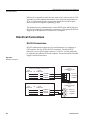
Electrical Connections ................................................................................................... BÑ2
RS-232 Connections .................................................................................................. BÑ2
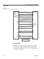
RS-422 Connections .................................................................................................. BÑ3
Shield Connection ......................................................................................................... BÑ4
Terminal Mode ............................................................................................................... BÑ5
Software Drivers ....................................................................................................... BÑ5
Error Checking .......................................................................................................... BÑ6
Setting Up the Terminal Mode ................................................................................ BÑ7
Terminal Mode Data Access .................................................................................... BÑ8
Network Mode................................................................................................................ BÑ8
Software Driver ......................................................................................................... BÑ8
Setting Up the Network Mode ................................................................................ BÑ9
Network Mode Request and Response Messages .............................................. BÑ10
Network Mode Request and Response Message Formats ................................ BÑ11
End of Text Control Character .............................................................................. BÑ14
Checksum ................................................................................................................. BÑ15
Error Checking ........................................................................................................ BÑ17
Test Program ............................................................................................................ BÑ17
PC to Dimension Communications Ð Optimized for Speed ............................... BÑ18
System Variable Data Access ..................................................................................... BÑ19
System Variable Commands ................................................................................. BÑ19
PRINT Commands .................................................................................................. BÑ20
LET Commands ....................................................................................................... BÑ21
LIST Commands ...................................................................................................... BÑ22
STAG Commands ................................................................................................... BÑ24
CTAG Commands ................................................................................................... BÑ24
Reading & Changing the Status of the System Functions via Digital Communication ....................................................................................................................... BÑ25
System Variable Descriptions ................................................................................ BÑ26
Example of System Variable Use .......................................................................... BÑ82
Error Messages ........................................................................................................ BÑ84
IEEE-488 Option Installation and ConÞguration ................................................... BÑ85
IEEE-488 Introduction ............................................................................................ BÑ85
IEEE-488 and Dimension ....................................................................................... BÑ85
IEEE-488 Installation ................................................................................................... BÑ85
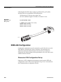
Cabling and Connections ....................................................................................... BÑ85
HA090933U002
iii
CSZ Dimension Series 60 UserÕs Manual
CSZ
IEEE-488 ConÞguration ............................................................................................... BÑ86
Dimension 8705 Configuration/Set up ................................................................ BÑ86
Dimension 8725 Configuration/Set up ................................................................ BÑ87
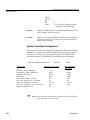
System Controller Configuration ......................................................................... BÑ88
Primary GPIB Address ........................................................................................... BÑ89
Secondary GPIB Address ....................................................................................... BÑ89
Timeout Setting ....................................................................................................... BÑ89
EOS Byte ................................................................................................................... BÑ89
Terminate Read on EOS ......................................................................................... BÑ90
Set EOI with EOS on Write .................................................................................... BÑ90
Type of Compare on EOS ...................................................................................... BÑ90
Set EOI with Last Byte of Write ............................................................................ BÑ90
Repeat Addressing .................................................................................................. BÑ91
IEEE-488 and Data Transfer........................................................................................ BÑ91
Data Transfer ........................................................................................................... BÑ91
IEEE-488 Hardware Bus .............................................................................................. BÑ91
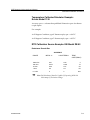
Handshake Lines ..................................................................................................... BÑ92
Interface Management Lines ................................................................................. BÑ93
Driver Software ....................................................................................................... BÑ93
IEEE-488 Bus Commands............................................................................................ BÑ94
Application Software .............................................................................................. BÑ96
Dimension Commands ........................................................................................... BÑ96
Sample Programs .................................................................................................... BÑ96
Appendix C Verification/Calibration Procedure
Required Prerequisites ................................................................................................. CÑ1
Required Equipment ..................................................................................................... CÑ1
Equipment SpeciÞcations ............................................................................................. CÑ2
Dimension Input Verification ...................................................................................... CÑ4
Cold Junction - Calibration .......................................................................................... CÑ6
Input Calibration ........................................................................................................... CÑ7
Thermocouple Error..................................................................................................... CÑ11
Index
iv
HA090933U002
CSZ Dimension Series 60 UserÕs Manual
Preface
Preface
This preface:
¥
Brießy describes the scope, organization, and contents of this manual.
¥
IdentiÞes and describes related documentation.
¥
Lists and deÞnes the conventions and terminology used in
Dimension¨ documentation and software.
¥
Explains how to get help.
Manual Scope
This manual contains information on the following:
¥
Using the Dimension Controller to operate the CSZ chamber.
¥
Dimension hardware component functions.
Your system may or may not include all of the products and features
discussed in this manual. If your system includes components other
than those listed above, refer to related documentation shipped with
your system.
Manual Organization and Contents
This manual contains information you will need in order to conÞgure and
operate the CSZ Dimension Controller. Manual contents are as follows:
Section 1. Operator Interface
A descriptive overview of DimensionÕs Graphic Operator Interface,
including Operation and ConÞguration screens, description of graphic
icons and menu screens, how to navigate the Graphic Operator Interface,
and terminology related to Graphic Operator Interface.
HA090933U002
v
CSZ Dimension Series 60 UserÕs Manual
Section 2. Operation
Description of the functions on the Dimension controller used to control
the CSZ chamber. DeÞnition, terminology and operation of PID process
control loops.
Section 3. Programmer
Describes Dimension Programmer functions and capabilities, includes
Programmer terminology, and explains how to enter, execute and monitor
a setpoint program.
Section 4 . ConÞguration
Description of the setup and conÞguration functions that can be used to
customize the Dimension controller.
Appendix A. Hardware/Wiring Connections
Explains how to install and set up Dimension system hardware, and
how to make external Þeld wiring and communication connections.
Appendix B. Communications
Explains how to communicate with Dimension via a serial link.
Includes all parameters needed for communications. Also describes
IEEE-488 communications.
Appendix C. VeriÞcation/Calibration Procedure
Provides procedures for calibration of your Dimension and veriÞcation
of inputs.
Conventions
In Dimension documentation and on-screen instructions, you will be
instructed to enter various system commands and information using
Graphic Operator Interface front panel controls. The following conventions are used:
¥
vi
Pressing the operator interface multi-function knob has the same effect
as pressing the Enter or Return key on a computer keyboard. When
you see Òpress ENTERÓ printed in an instruction, press the knob to
enter a selection or command into the system.
HA090933U002
CSZ Dimension Series 60 UserÕs Manual
¥
The operator interface multi-function knob can be turned clockwise or
counterclockwise to scroll through or select information. In the
documentation, CW = clockwise and CCW = counterclockwise.
¥
The Graphic Operator Interface (OI) continuously displays a set of
graphic icons on the right-hand side of the screen. The meanings and
use of these graphic symbols are deÞned in section 3 of this manual.
¥
The operator interface displays a graphic CURSOR which indicates
the currently active data entry Þeld or selection on a screen. In its
ÒhomeÓ position, the cursor is displayed as a blinking square graphic
object between the screen title and time indicator on the top line of
the screen.
¥
When a window is displayed on a screen, the cursor disappears and
another box with a smaller box inside is displayed.
¥
When an icon or data entry Þeld is displayed in reverse video on a
screen, that icon or Þeld is currently selected.
¥
When an alarm becomes active, the alarm icon begins to blink. When
all alarms are acknowledged on the Alarm Status screen, the icon stops
blinking.
¥
Dimension display parameters are shown in bold type. Example:
Configur_Select.
How to Get Help
On many operator interface displays, messages are displayed that will tell
you how to proceed or how to correct an error. Also, pop-up ÒhelpÓ
. Press the
windows can be called up by simply pressing the Help key
Help key again, or the knob, to make the window disappear.
HA090933U002
vii
CSZ Dimension Series 60 UserÕs Manual
viii
HA090933U002
CSZ Dimension Series 60 UserÕs Manual
Operator Interface Description
Section 1
Section
1
Operator Interface Description
Section Objectives
Section 1 provides the following information:
¥
Description of Dimension Graphic Operator Interface functions
¥
Functions of Interface graphic icons and menu screens
¥
How to navigate the Graphic Operator Interface
¥
Terminology related to Interface Operator and ConÞguration screens
Introduction
The Dimension Industrial Process Manager graphic operator interface is a
self-contained, intelligent unit equipped with its own on-board microprocessor and memory. The operator interface provides all the tools needed
for system conÞguration, operation, and monitoring of a Dimension
Industrial Process Manager.
In all hardware conÞgurations, operator interface functions and features
are identical. Operator interface features include:
HA090933U002
¥
An easy-to-use set of controls for both conÞguration and operation
¥
A set of highly readable, backlit screen displays using both text and
graphics
¥
Dedicated ÒhelpÓ key
¥
Multi-function knob for data entry and parameter selection
¥
Two user-programmable Òfunction keysÓ for combining frequently
used multiple steps into one function
¥
User deÞnable displays
¥
Screens in text/numeric, X-Y charts, bar charts
¥
User deÞnable screens and process terminology
¥
An integrated memory card slot that can read from and write to
removable data storage memory cards
1-1
CSZ Dimension Series 60 UserÕs Manual
Operator Interface Description
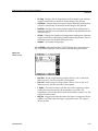
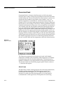
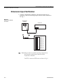
Front Panel Controls
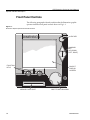
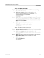
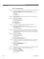
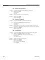
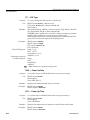
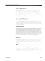
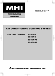
The following paragraphs identify and describe the Dimension graphic
operator interface front panel controls shown in Fig. 1-1.
Figure 1-1.
Dimension Graphic Operator Interface Front Panel
DIMENSION
HELP KEY
DIAMOND
KEY
(UP, DOWN,
LEFT, RIGHT)
FUNCTION
KEYS
BACKLIT
DISPLAY
SCREEN
MEMORY CARD SLOT
1-2
MULTI-FUNCTION KNOB
HA090933U002
CSZ Dimension Series 60 UserÕs Manual
Operator Interface Description
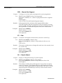
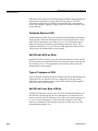
Help Key
Help Key
Located in the upper right-hand corner of the front panel, the help key is
designed to perform two functions:
DIMENSION
¥
Cancel an entry. Pressing the help key when entering a value will
cancel the entry.
¥
Provide on-screen help. Pressing the help key opens a ÒhelpÓ window
containing instructions for the currently accessed Þeld. Pressing the
help key a second time, or the multi-function knob, closes the window.
➥
Note: During some operations, help messages are displayed automatically if you attempt to perform actions not permitted on the
currently displayed screen.
Most help messages are an integral part of system software and are not
user-deÞnable. However, on the Alarm Display ConÞguration screen, you
may enter alarm-speciÞc messages that will display when the help key is
pressed at the Alarm Status screen.
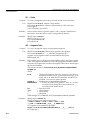
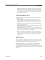
Diamond Key
Diamond Key (Four-way Keypad)
DIMENSION
The graphic process display screen is organized in a horizontal/vertical
hierarchy. A set of six graphic icons displayed on the right side of the
screen shows where you are located vertically in the screen display
hierarchy by displaying the icon in inverse video (See Fig. 1-3 on page 10).
The diamond key located directly below the help key is used to perform
one function: to exit the currently displayed screen and call up another
screen. The diamond key has four selections:
Up
UP Ð Accesses the next icon up and displays the Þrst screen for the icon.
DOWN Ð Accesses the next icon down and displays the Þrst screen for the icon.
LEFT Ð Displays the next screen to the left.
Left
Right
RIGHT Ð Displays the next screen to the right.
See ÒDisplay SummaryÓ on page 1-11.
Down
HA090933U002
1-3
CSZ Dimension Series 60 UserÕs Manual
Operator Interface Description
DIMENSION
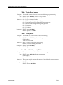
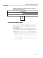
Multi-Function Knob
The multi-function knob (hereafter called the knob) is used to move the
graphic ÒcursorÓ from Þeld to Þeld on Dimension screen displays. In its
ÒhomeÓ (inactive) position, the cursor is located between the screen title
and time indicator on the top line of the screen. If a window is displayed, a
second, smaller box is displayed inside another box to the left of the cursor
(see Fig. 1-3 on page 10).
Multi-Function Knob
The following sequence explains how you can make selections and enter
or change information on Dimension screen displays.
1. When a screen is Þrst displayed after being called up, the cursor is
located in its ÒhomeÓ position on the top row of the screen.
2. If you press the Help key, a help window displays that describes screen
and knob functions.
3. Press the Help key again, or the knob, to close the help window.
4. If any items on the screen are selectable, the knob can be turned CW to
move the cursor to the Þrst selectable item on the screen.
5. If the knob is pressed, the item is selected and one of two actions occurs:
Ð
A window opens for further input.
Ð
The selected item is displayed in inverse video and you can change
the item in one of the following ways:
CHARACTER ENTRY Ð Display one character at a time by turning the
knob CW or CCW and press ENTER when the character you wish to
select is displayed. This input method displays the full ASCII alphanumeric character set as the knob is turned.
NUMBER ENTRY Ð Display one number at a time by turning the knob
CW or CCW and press ENTER when the number you wish to select is
displayed. This input method displays numbers in the correct format
as the knob is turned. Parameters such as time, date, and passcodes are
set with limits, as are control parameters and variables.
➥
Note: If a number is entered outside a ÞeldÕs designated range, the
number will not be accepted. The previous value will redisplay in
the data entry Þeld. Length varies from Þeld to Þeld.
PARAMETER SELECTION Ð As the knob is turned CW or CCW, a list
of selectable items is displayed; for example, ÒR u n , H o l d , S t a r t . Ó
When the correct entry is displayed, press ENTER to
select the item.
FUNCTION SELECTION Ð Some entries are functions that will be
executed when ENTER is pressed. For example, scrolling to the C L O S E
entry in a window and pressing ENTER closes the window.
1-4
HA090933U002
CSZ Dimension Series 60 UserÕs Manual
Operator Interface Description
➥
Note: If an item is selectable (cursor can be moved to it), the help key
can be pressed and a help message for the item in the cursor will
be displayed. If an item is selected by pressing ENTER, a screen
change cannot be made until the cursor reappears.
Function Key Labels
DIMENSION
PgmStart - push button
Function Keys
¥
to view current active recipe
¥
view current segment
¥
select new recipe to start
¥
select memory card to save recipes
Run/Hold - After recipe is started label will display HOLD. Push button
to HOLD (stop clock). Label will now read RUN. Push bottom to resume
program.
Memory Card Slot
A slot is provided on the graphic operator interface front panel for
insertion of a credit card-sized memory card. The operator interface
can read from, write to, delete, or format memory cards.
DIMENSION
Information that can be stored on Dimension memory cards includes:
Memory Card Slot
¥
Programmer proÞle programs 1Ð15 (Recipes)
¥
Total memory image of Dimension conÞguration and operational
parameters (Mem_Img)
¥
Display conÞguration (DspConf_)
¥
Function key conÞguration (MacroKy_)
¥
Optional Custom Control Program (CLCstart)
Using Memory Cards
A slot is provided on the operator interface front panel for insertion of
credit card-sized memory cards. ConÞguration, control parameters and
data can be retrieved from or stored on these cards.
HA090933U002
1-5
CSZ Dimension Series 60 UserÕs Manual
Operator Interface Description
➥
Note: The memory cardÕs battery life is approximately Þve years under
normal operating condition. Batteries can be replaced; call CSZ
customer service department for ordering information.
Information that can be stored on Dimension memory cards includes:
¥
Setpoint proÞle programs (R e c i p e s )
¥
Total memory image of Dimension conÞguration and operational
parameters (M e m - I m g )
¥
Display conÞguration (D S P C o n f )
¥
Function key conÞguration (M a c r o k y _ )
¥
Custom features (C L C s t a r t )
Whenever you make changes to Dimension parameters or data, the new
information should be saved on a memory card.
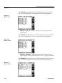
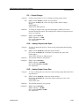
Memory Card Operation
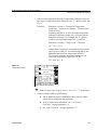
The following procedure explains how you can save your new conÞguration data onto removable memory cards. With your information saved
on one or more memory cards, you can load the data into Dimension
system memory at any time.
Save your data onto memory cards as follows:
1. Use the diamond key to access the setup icon. Scroll down to the
ÒunitÓ parameter and press ENTER. The system will display the Unit
Operation screen, shown in Þgure 1-2.
UNIT
ICON
2. Insert a memory card into the card slot on the operator interface front
panel.
!
Important: If you wish to write data to a memory card, be sure that
the write-protect switch on the card is set to the ÒNOÓ position.
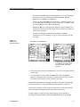
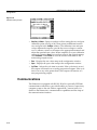
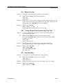
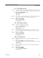
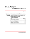
3. Use the knob to select the M E M _ C A R D Þeld. The system will display
the Memory Card Operation Window shown in Fig. 1-2. The following
information and functions are provided in this window:
Ð
1-6
The Þrst line describes the current status of the memory card slot:
I N S E R T M E M O R Y C A R D or U N F O R M A T T E D M E M O R Y C A R D .
If a card is not installed, ÒI n s e r t M e m c r d Ó is displayed. If an
installed card has not been initialized and is unreadable,
ÒU n f o r m a t M e m c a r d Ó will be displayed.
HA090933U002
CSZ Dimension Series 60 UserÕs Manual
Operator Interface Description
Figure 1-2.
Memory Card
Operation Window
Ð
The function (F U N C ) selection Þeld permits you to scroll through
and select from a list of functions including R E A D , W R I T E ,
D I R E C T (ory), F O R M A T , and D E L E T E .
Ð
When you select the D I R E C T (ory) function, a window permits you
to scroll through the directory of Þles on the card. The name, date,
and size (Kbytes) of each Þle are displayed.
Ð
If R E A D or W R I T E is selected and a Memory card is installed, the
selector box moves to the FILE Þeld where the Þle to be written or
read can be speciÞed.
Ð
A status line displays card status parameters including
write-protect on/off, battery low/good, read/write fail, and Þle
too large.
Select Memory Card Parameter
A window opens to allow access
to the Memory Card Read, Write,
Directory Format, and Delete
Functions
4. If necessary, format the installed memory card. This will delete all data
on the card.
5. To write a Þle to a card, select the F U N C Þeld. Select the W R I T E
function. The selector box will move to the F I L E Þeld. Select or enter
the name of the Þle that is to be written to the card.
If additional information is required, a window will open with prompts
for more information. Enter the additional information as required.
At this point, the data will be written to the memory card under the Þle
name you speciÞed. Repeat this for other Þles as necessary.
To read a memory card Þle into system memory, follow the above
procedure but specify R E A D rather than W R I T E functions as required.
HA090933U002
1-7
CSZ Dimension Series 60 UserÕs Manual
Operator Interface Description
Memory Card Information
The memory card Þles contain the following Dimension information:
1. R e c i p e s (Recipes):
Ð
The programmer build (PgBuild) segment table of 256 segments.
Ð
Recipe Tag Names (ProgName) of the programmer glossary.
Ð
Starting Segment numbers (Start_Seg) associated with the eight
program recipe tag names (default names Recipe_1 to Recipe_8).
2. M e m _ I m g (Memory Image):
Ð
Unit conÞguration: Full and limited access passwords, system
mode, Function key tag names.
Ð
Glossary conÞguration: System glossary (GLOS_SYS), programmer
glossary (GLOS_PRG) excluding Recipe Tag Names (ProgName), Loop
glossary (GLOS_LOP), I/O glossary (GLOS_IO).
Ð
Process conÞguration: Programmer conÞguration (CONF_PRG),
Loop conÞguration (CONF_LOP) including Auto Tune parameters,
Alarm conÞguration (CONF_ALM), Output conÞguration
(CONF_OUT).
Ð
Analog Input conÞguration: (not calibration).
Ð
Analog Output conÞguration: (not calibration).
Ð
Remote Output conÞguration.
Ð
Time Proportioning Output conÞguration.
Ð
Contact Output conÞguration.
Ð
Communication conÞguration.
Ð
The following Process Settings: Programmer Option settings
(PgOption), Analog Input Alarm settings (InputAlm), Manual
Reset (ManRst), Setpoint Source (SptSrc), Loop Mode (LpMode).
Ð
Loop PID parameters for PID groups 1Ð5: (Gain, Reset, Rate).
Ð
Loop Alarm settings for Alarm Groups 1Ð5: (Loop_Alm): (HiHiPV,
LoLoPV, HiPV, LoPV, HiHiDV, LoLoDV, HiDev, LoDev)
3. D s p C o n f _ (Dimension Display ConÞguration):
1-8
Ð
Overview display screens (DCON_OVR).
Ð
Programmer display screens (DCON_PRG).
Ð
Loop display screens (DCON_LOP).
Ð
Logic display screens (DCON_LOG).
Ð
Alarm Messages (DCON_ALM)
HA090933U002
CSZ Dimension Series 60 UserÕs Manual
Operator Interface Description
4. M a c r o K y _ (Function Key ConÞguration):
Ð
Function key number 1 function conÞguration (MacroKy1)
excluding tag name.
Ð
Function key number 2 function conÞguration (MacroKy2)
excluding tag name.
5. C L C S t a r t (custom features):
Ð
To be determined by CSZ engineering (optional)
Items Not Stored on Card:
¥
Time of Day
¥
Date
¥
Contrast
¥
Backlight
¥
UNIT_CNF glossary name parameter
¥
Mnemonic (linear range characters for process variable units)
¥
EngUnits (Centigrade, Fahrenheit, Linear): The engineering units are
not changed by memory card functions unless the ÒInput typeÓ
parameter selected in the Dimension is different than stored on the
memory card. When the memory card restores the Input type to a
Thermocouple or RTD, the EngUnits are set to Centigrade. When the
memory card restores the input type to Current or Voltage ranges, the
EngUnits are set to Linear.
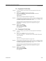
Screen Display Format
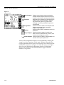
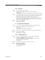
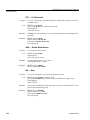
As shown in Fig. 1-3, every Dimension screen display includes the
following common elements:
HA090933U002
1-9
CSZ Dimension Series 60 UserÕs Manual
Operator Interface Description
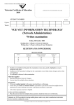
Figure 1-3.
Dimension Screen
Display Format
SCREEN TITLE
OPEN
WINDOW INDICATOR
CURSOR
"HOME" POSITION
TIME
DISPLAY AREA
FUNCTION KEY LABELS
GRAPHIC ICONS (CURRENT SELECTION DISPLAYED IN INVERSE VIDEO)
SCREEN TITLEÑThe title of the currently selected screen is displayed on
the top row of the screen. (Most screen titles are user-deÞnable.)
CURSOR ÒHOMEÓ POSITIONÑA blinking graphic ÒboxÓ displayed on the
top row of the screen indicates that the cursor (controlled by turning the
knob) is located in its ÒhomeÓ (inactive) position. Whenever you call up a
new screen, the cursor is displayed in its home position.
OPEN WINDOW INDICATORÑA second, smaller box displayed inside
another box to the left of the cursor ÒhomeÓ position indicates a window
has been selected and is open in the display area. When the Open Window
Indicator is active, the cursor home position indicator is not displayed (see
Fig. 1-4).
CURRENT TIMEÑThe current time is displayed in the upper right-hand
corner. Current time is displayed in standard 24-hour (HH:MM:SS)
format.
GRAPHIC ICONSÑThe right-hand side of the screen displays six graphic
icons, or symbols, which represent various system functions. The
currently selected icon (selectable with diamond key) is displayed in
inverse video.
1-10
HA090933U002
CSZ Dimension Series 60 UserÕs Manual
Operator Interface Description
FUNCTION KEY LABELSÑThe bottom row of the screen always displays
user-deÞnable labels for the two function keys located directly below the
screen.
DISPLAY AREAÑThe contents of the current screen are visible in the
Òdisplay areaÓ shown in Fig. 1-3. The location of the cursor (when away
from the ÒhomeÓ position) is depicted by a graphic box or rectangle
surrounding the currently selected data entry Þeld or selection, as shown
in Fig. 1-4.
Figure 1-4.
Cursor Location, in This
Case in an Open Window.
Note Open Window
Indicator.
OPEN WINDOW
INDICATOR
CURSOR
LOCATION
currently
selected
parameter
Display Summary
The Graphic Operator Interface provides all of the tools needed for
Operation and the ConÞguration of a Dimension Industrial Process
Manager. Operation can be described as the Dimension doing the work it
was purchased to do, and ConÞguration as the process of setting up the
unit to know how to do the work.
The Operation displays are divided into the icon/function groups
described below and in Section 2 of this guide.
HA090933U002
1-11
CSZ Dimension Series 60 UserÕs Manual
Operator Interface Description
Figure 1-5.
Operation Icons
Displays current chamber air temp and relative
humidity and their setpoints. Allows access to the
chamber control functions and the product window.
Designed to be conÞgured on a process basis to
Overview
Displays show process parameters. Displays
may be text, bar graph or xy graph format.
Changing of process parameters may also be
accomplished.
Used to monitor the status of the setpoint/event
Programmer
Displays programmer and to create/edit
program recipe segments.
Used to monitor speciÞc chamber functions and
Utilities
parameters.
Setup Displays Used to monitor the status of control loops.
Allows access to date/time entry, memory card
functions and conÞguration access
Alarm Displays Used to monitor the status of, acknowledge and
set limits for loop and input alarms.
Unit Operation
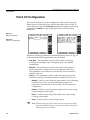
Access to the ConÞguration displays is accomplished by selecting the
ÒsetupÓ icon, then ÒenteringÓ on the ÒunitÓ selection. Next select the
ConÞgur parameter shown on the UNIT display. This will bring up the
UNIT_CNF screen shown in Figure 1-6. From this screen, move up or
down to access the desired conÞguration function. ConÞguration
displays are divided into the areas described in Figure 1-6 and in
Section 4, ConÞguration.
1-12
HA090933U002
CSZ Dimension Series 60 UserÕs Manual
Operator Interface Description
Figure 1-6.
ConÞguration Icons
Used to set access levels, deÞne function key
ConÞguration functions, enable/disable display
groups and Display view/alter unit options.
Used to modify the default factory terminology
Tagname
to Displays match that of your process and
application.
Used to assign input, output and function
Patch I/O
parameters to conÞgure the Dimension to your
application.
Used to format and deÞne operation displays to
Display
ConÞguration match your user, application and
process needs.
Used to deÞne input and output range and type
I/O Calibration
information. Access to the calibration functions
is also provided. Note that all Dimension inputs
and outputs types are factory calibrated.
Communication Used to set up parameters for the RS-232,
RS-422 Displays and IEEE-488 communication
ports.
Unit
HA090933U002
1-13
CSZ Dimension Series 60 UserÕs Manual
Operator Interface Description
1-14
HA090933U002
CSZ Dimension Series 60 UserÕs Manual
Operation
Section 2
Section
2
Operation
This section describes the operation parameters available on the
Dimension controller that are used to control the CSZ chamber.
This section assumes that the user is familiar with the conventions
and operation of the Dimension Custom Logic controller. Refer to
Section 1, Operator Interface Description, of this manual for basic
operational information.
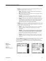
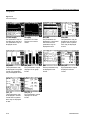
Fig. 2-1 and Fig. 2-2 are screen maps that illustrate the various Operations
and ConÞguration screens of the Dimension.
HA090933U002
2-1
CSZ Dimension Series 60 UserÕs Manual
Operation
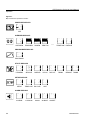
Figure 2-1.
Map of Dimension Operations Screens
POWER-UP DISPLAYS
CSZ
OVERVIEW DISPLAYS
OVERVIEW
TEMPVIEW
RHVIEW
TEMP RH
É
CMPRSR
DIG IN
DIG OUT
TEMPTUNE RHTUNE
PROGRAMMER DISPLAYS
PROGRAMR
UTILITY DISPLAYS
UTILMENU
SERVICE
REMIN
REMOUT TIMING
SETUP DISPLAYS
SETUP
TEMPLOOP RH LOOP
UNIT
ALARM DISPLAYS
ALARMS
2-2
LOOPALM
INALM
ALMHIST ALMSET
HA090933U002
CSZ Dimension Series 60 UserÕs Manual
Operation
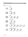
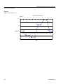
Figure 2-2.
Map of Dimension ConÞguration Screens
UNIT CNF
UNIT CNF
TAG NAME
TAGNAME
PRGGLOS
CONFIG
PATCH I/O
CONFLOP
CONFALM
DISPLAY CONFIG
DISPLAY
CONFIG
DCON OVR
INPUT/OUTPUT DISPLAYS
I/O CAL
INPUTS
REMOTE IN
ANA OUT
RS422
IEEE-488
DIGOUTCF
COMMUNICATION DISPLAYS
COMM
HA090933U002
RS232
2-3
CSZ Dimension Series 60 UserÕs Manual
Operation
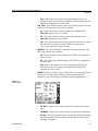
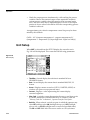
When the Dimension is powered up, the CSZ screen (Fig. 2-3) is the Þrst
screen displayed. This display contains the following parameters:
Figure 2-3.
CSZ Display
¥
AIR TEMP - Displays the current value of the chamber air temperature.
¥
%RH - Displays the current value of the relative humidity.
¥
Temp Sp - Set and display the current temperature setpoint that the
chamber will try to control to when in the Automatic mode. This
setpoint can be entered by the operator when the programmer is in a
HoldOper condition or at program end. If the programmer is running,
the setpoint will be controlled by the programmer.
¥
%Rh Sp - Set and display the current relative humidity setpoint the that
the chamber will try to control to when in the Automatic mode. This
setpoint can be entered by the operator when the programmer is in a
HoldOper condition or at program end. If the programmer is running,
the setpoint will be controlled by the programmer.
¥
COND SYS - Turns On and Off the heating and cooling functions. The
following 3 modes are available:
¥
2-4
Ð
On - Turns the conditioning system on and displays the COND SYS
tagname in inverse video.
Ð
Off - Turns the conditioning system off and displays the COND
SYS tagname in normal video.
Ð
Pgm - Allows the Þrst event in the programmer (Event d) to control
the status of the conditioning system and displays the COND SYS
tagname in inverse video.
HUMD SYS - Turns On and Off the relative humidity functions. The
following 3 modes are available:
Ð
On - Turns the relative humidity system on and displays the
HUMD SYS tagname in inverse video.
Ð
Off - Turns the relative humidity system off and displays the
HUMD SYS tagname in normal video.
HA090933U002
CSZ Dimension Series 60 UserÕs Manual
Operation
Ð
¥
¥
¥
Pgm - Allows the second event in the programmer (Event e) to
control the status of the relative humidity system and displays the
HUMD SYS tagname in inverse video.
AUX_COOL - Turns On and Off the optional CO2 and LN2 boost cooling
functions. The following 3 modes are available:
Ð
On - Turns the auxiliary cooling system on and displays the
AUX_COOL tagname in inverse video.
Ð
Off - Turns the auxiliary cooling system off and displays the
AUX_COOL tagname in normal video.
Ð
Pgm - Allows the third event in the programmer (Event f) to control
the status of the auxiliary cooling system and displays the
AUX_COOL tagname in inverse video.
PURGE/FC - Turns On and Off the optional GN2 purge functions. The
following 3 modes are available:
Ð
On - Turns the purge on and displays the PURGE/FC tagname in
inverse video.
Ð
Off - Turns the purge off and displays the PURGE/FC tagname in
normal video.
Ð
Pgm - Allows the fourth event in the programmer (Event g) to
control the status of the purge and displays the PURGE/FC
tagname in inverse video.
PRODUCT - Opens a window (Fig. 2-4) that allows the setting of product
High and Low limits along with the product guaranteed soak
deviation value. This display contains the following parameters:
Figure 2-4.
Product Display
HA090933U002
Ð
AIR TEMP - Displays the current value of the chamber air temperature.
Ð
PRODTEMP - Displays the current value of the product temperature.
Ð
Hi Limit - Set and display the value at which the product limit high
temperature alarm will shut down the chamber. A critical alarm
message will appear.
2-5
CSZ Dimension Series 60 UserÕs Manual
Operation
Ð
Lo Limit - Set and display the value at which the product limit low
temperature alarm will shut down the chamber. A critical alarm
message will appear.
Ð
Alarm - Displays the current status of the product alarm. When OK
is displayed, no alarms are active. When Tripped is displayed, one
of the product alarms is still active.
Ð
GSProdDv - Set and display the maximum deviation allowed
between the product temperature and the chamber setpoint. If this
deviation value is exceeded and Product is chosen for the
guaranteed soak parameter in the current programmer segment
(See Section 4, ConÞguration), the programmer will be put into a
HoldSoak condition.
Ð
PgmMode - Set and displays the current mode of the programmer.
The following selections are available here:
¥
HoldOper - Holds the program execution at the current point.
¥
Run - Run the program from the current point.
¥
PG_END - The program has run to completion. This is a
display only function.
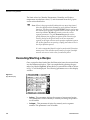
The overview icon is used to customize displays in a variety of formats
with parameters speciÞc to the users applications. When this icon is
selected the display shown in Fig. 2-5 will be displayed. Up to 7 different
overview screens are available to be conÞgured. Overviews 1-3 and 11- 12
have been conÞgured with speciÞc functions and cannot be changed. This
display contains the following parameters:
Figure 2-5.
Overview Display
2-6
¥
TempView - Displays the chamber temperature and setpoint in an XY
Chart format.
¥
%RH View - Displays the relative humidity and setpoint in an XY Chart
format.
¥
Temp %RH - Displays the Chamber temperature and relative humidity
in an XY Chart format.
HA090933U002
CSZ Dimension Series 60 UserÕs Manual
Operation
¥
OVIEW__4 - OVIEW_10 - User conÞgurable overview screens.
¥
TempTune - Contains the active parameters to be used when tuning the
temperature control loop.
¥
RH Tune - Contains the active parameters to be used when tuning the
humidity control loop.
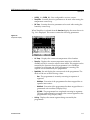
When TempView is selected from the Overview display, the screen shown in
Fig. 2-6 is displayed. This screen contains the following parameters:
Figure 2-6.
TempView Display
¥
Air Temp - Displays the current air temperature of the chamber.
¥
Temp Sp - Displays the current temperature setpoint to which the
chamber will try to control to when in Auto mode. This setpoint can be
entered by the operator when the programmer is in a HoldOper
condition or at program end. If the programmer is running, the
setpoint will be controlled by the programmer.
¥
PgmMode - Set and display the current mode of the programmer. The
mode will be one of the following values:
¥
HA090933U002
Ð
Run - The programmer is currently executing its sequence of
segments.
Ð
HoldOper - Execution of the programmer has been stopped due to
operator intervention.
Ð
HoldSoak - Execution of the programmer has been stopped due to a
guaranteed soak condition (Display Only).
Ð
PG_END - The programmer has completed executing its segments.
The next segment must be set equal to the current segment for the
programmer to stop (Display Only).
CurSeg - Displays the current segment being executed by the
programmer.
2-7
CSZ Dimension Series 60 UserÕs Manual
Operation
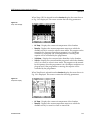
When %RH View is selected from the Overview display, the screen shown
in Fig. 2-7 is displayed. This screen contains the following parameters:
Figure 2-7.
%RH View Display
¥
%Rel Hum - Displays the current relative humidity for the chamber.
¥
%Rh Sp - Displays the current humidity setpoint to which the chamber
will try to control to when in Auto mode. This setpoint can be entered
by the operator when the programmer is in a HoldOper condition or at
program end. If the programmer is running, the setpoint will be
controlled by the programmer.
¥
PgmMode - Set and display the current mode of the programmer. The
mode will be one of the following values:
¥
2-8
Ð
Run - The programmer is currently executing its sequence of
segments.
Ð
HoldOper - Execution of the programmer has been stopped due to
operator intervention.
Ð
HoldSoak - Execution of the programmer has been stopped due to a
guaranteed soak condition (Display Only).
Ð
PG_END - The programmer has completed executing its segments.
The next segment must be set equal to the current segment for the
programmer to stop (Display Only).
CurSeg - Displays the current segment being executed by the
programmer.
HA090933U002
CSZ Dimension Series 60 UserÕs Manual
Operation
When Temp %RH is selected from the Overview display, the screen shown
in Fig. 2-8 is displayed. This screen contains the following parameters:
Figure 2-8.
Temp %RH Display
¥
Air Temp - Displays the current air temperature of the chamber.
¥
Temp Sp - Displays the current temperature setpoint to which the
chamber will try to control to when in Auto mode. This setpoint can be
entered by the operator when the programmer is in a HoldOper
condition or at program end. If the programmer is running, the
setpoint will be controlled by the programmer.
¥
%Rel Hum - Displays the current relative humidity for the chamber.
¥
%Rh Sp - Displays the current humidity setpoint to which the chamber
will try to control to when in Auto mode. This setpoint can be entered
by the operator when the programmer is in a HoldOper condition or at
program end. If the programmer is running, the setpoint will be
controlled by the programmer.
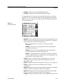
When TempTune is selected from the Overview display, the screen shown in
Fig. 2-9 is displayed. This screen contains the following parameters:
Figure 2-9.
TempTune Display
HA090933U002
¥
Air Temp - Displays the current air temperature of the chamber.
¥
Temp Sp - Displays the current temperature setpoint to which the
chamber will try to control to when in Auto mode.
2-9
CSZ Dimension Series 60 UserÕs Manual
Operation
¥
Dev_01 - Displays the difference between the actual air temperature
and the temperature setpoint.
¥
PIDTyp_1 - Displays the current PID type. When in Dual, PID group 1 is
for the heat output and PID group 2 is for the cool output.
¥
CurPIDGp - Displays the active PID group.
¥
Gain__01 - Set and display the PID gain value for the currently accessed
PID group.
¥
Rate__01 - Set and display the PID rate value for the currently accessed
PID group.
¥
Reset_01 - Set and display the PID rate value for the currently accessed
PID group.
¥
Heat - Displays the calculated heating output.
¥
Cool - Displays the calculated cooling output.
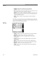
When RH Tune is selected from the Overview display, the screen shown in
Fig. 2-10 is displayed. This screen contains the following parameters:
Figure 2-10.
RH Tune Display
2-10
¥
%Rh - Displays the current relative humidity of the chamber.
¥
%Rh Sp - Displays the current humidity setpoint to which the chamber
will try to control to when in Auto mode.
¥
Dev_02 - Displays the difference between the actual humidity and the
humidity setpoint.
¥
PIDTyp_2 - Displays the current PID type. When in Dual, PID group 1 is
for the humidify output and PID group 2 is for the de-humidify
output.
¥
CurPIDGp - Displays the active PID group.
¥
Gain__02 - Set and display the PID gain value for the currently
accessed PID group.
¥
Rate__02 - Set and display the PID rate value for the currently accessed
PID group.
¥
Reset_02 - Set and display the PID rate value for the currently accessed
PID group.
HA090933U002
CSZ Dimension Series 60 UserÕs Manual
Operation
¥
Humidify - Displays the calculated humidify output.
¥
De-Humid - Displays the calculated de-humidify output.
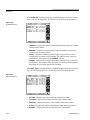
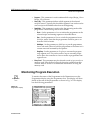
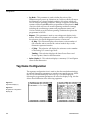
The programmer icon is used to build, modify and monitor a real time
program. For a more detailed description of the programming functions,
refer to Section 4, ConÞguration, in this manual. This display contains the
following parameters:
Figure 2-11.
Programmer Display
¥
HA090933U002
PgmMode - Set and display the current status of the programmer. These
functions may also be done be pressing the Þrst Macro key ÒPgmStatÓ.
The mode will be one of the following values:
Ð
Run - The programmer is currently executing its sequence
of segments.
Ð
HoldOper - Execution of the programmer has been stopped due
to operator intervention.
Ð
HoldSoak - Execution of the programmer has been stopped due
to a guaranteed soak condition (Display Only).
Ð
PG_END - The programmer has completed executing its segments.
The next segment must be set equal to the current segment for the
programmer to stop (Display Only).
¥
StrtPgr1 - Opens a window to select which Recipe to run, to start
and stop the current recipe selected and to display the status of
the current recipe.
¥
SegTime - Displays the time remaining in the currently active segment.
¥
TimeLeft - Display the total time remaining in the currently
active recipe.
¥
PgTmp_Sp - Displays the current temperature setpoint that the chamber
will try to achieve during the execution of the segment.
¥
Pg%RH_SP - Displays the current humidity setpoint that the chamber
will try to achieve during the execution of the segment.
¥
CurSegmt - Displays the number of the current segment being executed.
2-11
CSZ Dimension Series 60 UserÕs Manual
Operation
¥
CycCount - Displays the number of recycles remaining.
¥
CurPIDGp - Display the current PID group being used.
¥
Evnts - Displays the current status of the events. An individual event is
On when the selected eventsÕ number is displayed.
¥
PgOption - Opens a window which allows the entry of time of day, and
date to start a program. It also allows access to the Guaranteed soak
deviation parameter settings.
¥
PgBuild - Opens a window to the parameters used for building a
program.
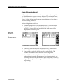
The utility icon is used to monitor speciÞc chamber functions. When this
icon is selected the display shown in Fig. 2-12 will be displayed. From this
display contains the following parameters:
Figure 2-12.
Utility Display
2-12
¥
SERVICE - Displays information needed when servicing the chamber.
¥
CMPRESOR - Displays Stage 1 and Stage 2 compressor data.
¥
DIG IN - Displays the status of the digital inputs on the machine
control board.
¥
DIG OUT - Displays the status of the digital outputs on the machine
control board.
¥
REM IN - Displays the status of the optional remote digital inputs.
¥
REM OUT - Displays the status of the optional remote digital outputs.
¥
ANALG IN - Displays the current analog input values.
¥
TIMING - Allows access to the compressor timeout and staged heat
and cool settings.
HA090933U002
CSZ Dimension Series 60 UserÕs Manual
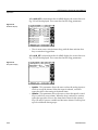
Operation
When SERVICE is selected from the UTILITY display, the screen shown in
Fig. 2-13 will be displayed. This screen has the following parameters:
Figure 2-13.
Service Display
HA090933U002
¥
AIR TEMP - Displays the current value of the chamber air temperature.
¥
RH - Displays the current relative humidity of the chamber.
¥
SYS1 HI - Displays the high pressure reading taken from the transducer
located on the discharge side of the compressor. A backup mechanical
pressure switch is also installed for the protection of the compressor.
¥
SYS1 LO - Displays the low pressure reading taken from the transducer
located on the suction side of the compressor.
¥
SYS1 DIS - Displays the discharge line temperature reading taken from
the thermocouple located on the discharge line of the compressor.
¥
SYS2 HI - Displays the high pressure reading taken from the transducer
located on the discharge side of the compressor. A backup mechanical
pressure switch is also installed for the protection of the compressor.
¥
SYS1 LO - Displays the low pressure reading taken from the transducer
located on the suction side of the compressor.
¥
SYS1 DIS - Displays the discharge line temperature reading taken from
the thermocouple located on the discharge line of the compressor.
2-13
CSZ Dimension Series 60 UserÕs Manual
Operation
When CMPRESOR is selected from the UTILITY display, the screen shown
in Fig. 2-14 will be displayed. This screen has the following parameters:
Figure 2-14.
Cmpresor Display
¥
Sys1 Hrs - Displays the total number of hours the Stage 1 compressor
has been running.
¥
Sys1Strt - Displays the number of times the Stage 1 compressor has
been started.
¥
T_OutCur - Displays the time remaining before the compressors will be
shut down.
¥
Sys1_PS - Displays the status of the oil pressure safety switch.
¥
Sys2 Hrs - Displays the total number of hours the Stage 2 compressor
has been running.
¥
Sys2Strt - Displays the number of times the Stage 2 compressor has
been started.
¥
Stag_Cur - Displays the time remaining before the Stage 2 compressor
will be started.
¥
Sys2_PS - Displays the status of the oil pressure safety switch.
¥
Cond Hrs - Displays the total number of hours that the air circulators
(conditioning system) have been running on the chamber.
When DIG IN is selected from the UTILITY display, the screen shown in
Fig. 2-15 will be displayed. This screen has the following parameters:
Figure 2-15.
Dig In Display
2-14
HA090933U002
CSZ Dimension Series 60 UserÕs Manual
Operation
¥
ExtLimit - Displays the status of the external high/low limit control. If
the input is On, the limit control is in a good state.
¥
Sys1_PS - Displays the status of the system 1 oil pressure safety switch.
¥
Sys2_PS - Displays the status of the system 2 oil pressure safety switch.
When DIG OUT is selected from the UTILITY display, the screen shown in
fFig. 2-16 will be displayed. This screen has the following parameters:
Figure 2-16.
Dig Out Display
HA090933U002
¥
Fans - Displays the status of the digital output that controls the air
circulator fans.
¥
Compr #1 - Displays the status of the digital output that controls the
Stage 1 compressor.
¥
Heater - Displays the status of the digital output that controls the
heating control relay.
¥
Cooling - Displays the status of the digital output that controls the
cooling solenoid.
¥
By-Pass - Displays the status of the digital output that controls the
by-pass solenoid.
¥
Compr #2 - Displays the status of the digital output that controls the
Stage 2 compressor.
¥
Hum Comp - Displays the status of the digital output that controls the
humidify air compressor.
¥
Humidify - Displays the status of the digital output that controls the
humidity solenoid.
¥
De-Humid - Displays the status of the digital output that controls the
de-humidify wet coil solenoid.
¥
RH Cool - Displays the status of the digital output that controls the
cooling solenoid (RH Mode).
¥
Max Heat - Indicated whether the chamber is calling for maximum heat
(used only with a dual stage heating system).
¥
Horn - Displays the status of the sonalert audible alarm output.
2-15
CSZ Dimension Series 60 UserÕs Manual
Operation
When REM IN is selected from the UTILITY display, the screen shown in
Fig. 2-17 will be displayed. This screen has the following parameters:
Figure 2-17.
REMIN Display
¥
RmtIN_01 - RmtIN_08 - Displays the status of the 8 optional remote
digital inputs.
When REM OUT is selected from the UTILITY display, the screen shown in
Fig. 2-18 will be displayed. This screen has the following parameters:
Figure 2-18.
REMOUT Display
¥
RmCOut01 - RmCOut08 - Displays the status of the 8 optional remote
digital outputs. These outputs are tied to Events 1 - 8 of the programmer.
When ANALG IN is selected from the UTILITY display, the screen shown in
Fig. 2-19 will be displayed. This screen has the following parameters:
Figure 2-19.
ANALGIN Display
2-16
HA090933U002
CSZ Dimension Series 60 UserÕs Manual
Operation
¥
Air Temp - Displays the air temperature in the chamber from a thermocouple located in the air stream at the discharge of the plenum.
¥
%Rel Hum - Displays the percentage of relative humidity reading from
a sensor located in the air stream at the discharge of the plenum.
¥
ProdTemp - Displays the current product temperature reading from a
thermocouple that is located inside the chamber and dedicated for the
customerÕs part.
¥
Hi Limit - Displays the chamber air temperature reading from a thermocouple located above the heating element behind the plenum. This is a
redundant sensor for chamber protection only.
¥
Unused 6 - An unused analog input.
When TIMING is selected from the UTILITY display, the screen shown in
Fig. 2-20 will be displayed. This screen has the following parameters:
Figure 2-20.
TIMING Display
HA090933U002
¥
Max Heat - Set the staged heating output value to cycle on max heat.
When set to 0%, the max and min cycle together.
¥
Max Cool - Set the staged cooling output value to cycle on max cool.
When set to 0%, the max and min cycle together.
¥
T_OutPre - The time-out timer will shut down the compressors when
cooling has not been used for the set number of seconds. The
compressors will not shut down while the humidity system is on. The
range is 30-180 seconds.
¥
Stag_Pre - Stagger start timer that starts the Stage 2 compressor the set
number of seconds after the Stage 1 compressor starts. The range is
30-120 seconds.
2-17
CSZ Dimension Series 60 UserÕs Manual
Operation
Process Control
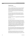
Control Loop DeÞnition
This topic is intended to provide a common base of terminology and
control loop theory to help you conÞgure and operate a control loop using
the CSZ Dimension Custom Logic Controller. A brief discussion of the
theory of process control is provided here, using the control of a home
furnace as an example.
Process Control
The fundamentals of process control affect your daily life in many ways.
For example, the furnace that heats your home operates under the
principles of process control. You control the temperature of the air in your
home by choosing a setting on the thermostat, which in turn controls the
furnace. In process control, a setting is referred to as a Òsetpoint.Ó A
setpoint is deÞned as Òthe desired value of a process variable.Ó In this
example, the process variable is the air temperature.
By establishing a desired air temperature setting for your home (setpoint),
you expect that gas or oil will be supplied to the furnace to heat the air.
The furnace is turned on when the temperature falls below the setpoint,
and turned off when the temperature rises above the setpoint. This type of
control action is often referred to as two position or Òon/offÓ control.
In more sophisticated thermostats, the amount of fuel delivered to the
furnace is regulated according to the number of degrees the actual air
temperature differs from the desired temperature. This difference is the
ÒerrorÓ or Òdeviation.Ó The deviation is detected by the thermostat, which
controls the amount of heat delivered by the furnace by controlling the
fuel valve feeding the burner. The valve in turn opens proportionately. If
the setpoint is reached, the valve receives a small signal or no signal at all.
It closes and very little heat, if any, is generated.
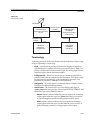
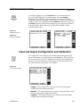
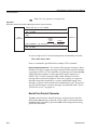
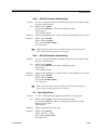
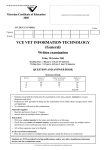
The device that senses the air temperature in your home (sensor) sends a
signal (feedback signal) to the temperature controller (thermostat). The
signal portrays the actual air temperature (Process Variable, or PV). The
thermostat compares the signal received with the setpoint (SP). A corresponding action (valve opens or closes) occurs depending on the
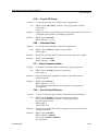
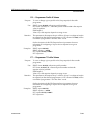
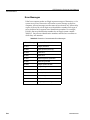
magnitude of the deviation (SPÐPV). This process is called a Òclosed loopÓ
process because there is a feedback signal and the controller adjusts the
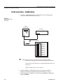
output automatically (Fig. 2-21).
2-18
HA090933U002
CSZ Dimension Series 60 UserÕs Manual
Operation
Figure 2-21.
Closed Loop Control
SETPOINT
SP
CONTROLLER
(Measures Deviation)
SPÐPV
FEEDBACK
SIGNAL
REGULATING
SIGNAL
FINAL
CONTROLLING
ELEMENT
(Proportioning Valve
in Furnances)
ENERGY
PV
SENSOR
(Measures
Temperature)
PROCESS
VARIABLE
(Home Air)
Terminology
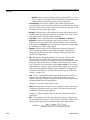
Following are terms used in this Manual and by Dimension when ConÞguring or Operating a control loop.
HA090933U002
¥
Alarm - A function that provides an indication (display or signal) if a
speciÞed limit is exceeded. Dimension provides 2 levels of High/Low
process variable and deviation alarms, high/low analog input alarms,
and Open sensor alarms for thermocouples.
¥
Analog Input (AI) - Refers to a sensor such as a thermocouple, RTD or
pressure sensor that is connected to the Dimension. This input is used
by Dimension for monitoring, control and display functions. This
parameter is referred to as A n l g I n on the Dimension.
¥
Configuration - This is the process of selecting Inputs, Outputs, Limits,
Constants, Enabling/Disabling features.
¥
Control Action - The control action of a loop deÞnes what type of
control output the loop provides. Choices are REVERSE, DIRECT, and
BIMODAL and can be deÞned as follows:
Ð
Reverse output is selected when the process requires an increasing
output signal when the setpoint is greater than the process variable.
A typical example would be a heating output control signal.
Ð
Direct output is selected when a process requires an increasing
output signal when the setpoint is less than the process variable. A
typical example would be a cooling output control signal.
2-19
CSZ Dimension Series 60 UserÕs Manual
Operation
Ð
Bimodal output is selected when a process requires both a reverse or
a direct output. An example of this would be an environmental test
chamber that has both heating and cooling capabilities.
¥
Control Output - The Control Output is the output signal from the
controller that is used to control an element (valve, heater) that affects
the process. The source of this output can be either the operator or the
calculated PID (see next page) output.
¥
Deviation -The deviation is the difference between the desired process
variable (setpoint) and the actual process variable. This value is used
with alarms and in the PID output calculation.
¥
Loop Mode - The Loop Mode may be either Automatic or Manual. In
Automatic (closed loop) mode the control loop calculates a control
output based on the current PID constants and the current deviation
from setpoint. In Manual (open loop) mode, the Operator is responsible
for adjusting the control output signal.
¥
Operator - Refers to the user of the Dimension making a change to
cause something within the instrument to happen. Examples are
changing Loop Mode from Auto to Manual, Setpoint Source from
Operator to Programmer.
¥
PID - Proportional, Integral and Derivative control. The term PID
control is used to describe the calculation that is done using the
proportional term (gain), the Integral term (reset), the Derivative term
(rate), the Setpoint, the Process Variable and the Span of the control
loop. The result of the calculation is the control output. It is the userÕs
responsibility to select the proper PID constants (gain, reset, and rate)
based upon the application that is being controlled. Selecting these
constants is referred to as TUNING the control loop (see ÒPID Loop
TuningÓ on page 2-27).
¥
Gain - Gain is a multiplication term expressing how the control loop
output varies with respect to the control loop deviation (process
variable - setpoint). The effect of gain on the control loop output can be
calculated from the following equation:
Output% = Deviation/Input Span x Gain.
¥
Reset -The reset factor is used to correct for process losses. Reset adds
or subtracts from the control loop output. The effect of Reset can be
calculated by the following equation:
Output% = åReset x Elapsed Time in minutes x Deviation/Inputs
span X 100.
¥
Rate - The rate factor is used to anticipate and correct for the process
lag and adjust the output to avoid overshoot. The effect of Rate on the
control loop output can be calculated by the following formula:
Rate ´ Current Ð PV % Last
OutPut% = --------------------------------------------------------------------------------------------------Minutes between PV Current and PV last
2-20
HA090933U002
CSZ Dimension Series 60 UserÕs Manual
Operation
¥
HA090933U002
PID Type - PID Type deÞnes which group of PID settings is used in a
process. There are up to 5 different PID groups that may contain
different values for gain, reset, and rate. Single, Dual, Programmed, or
Select Adaptive types are available.
Ð
Single PID is used when one set of PID constants is to be used at all
times. Group 1 is always used if single is selected.
Ð
Dual PID is used when one set of PID constants is to be used for
Reverse output (group #1) and another set is to be used for Direct
output (group #2).
Ð
Programmed PID is used when the real-time programmer (see
Section 4, ConÞguration) is used to select which PID group is to be
used on each segment.
Ð
Select Adaptive PID is used when you wish to alter PID constants
based upon the value of the process variable.
¥
Real-Time Programmer - A function within Dimension to generate a
Setpoint or event that can vary with time. The programmer can be
used to ramp a setpoint from one value to another or turn an event on
or off over a user-speciÞed time segment. Multiple time
segments/setpoints/events are used to make up a real-time program.
¥
Setpoint (SP) - Setpoint is deÞned as the desired value for the PV. This is
the value the Dimension tries to achieve when in automatic control.
¥
Setpoint Source - DeÞnes what provides the setpoint to a control loop.
In a Dimension this may be the Operator, a Real-Time Programmer or a
Remote Source. A remote source may be an external device (such as
another controller) or another control loop within the Dimension.
¥
Span - The difference between the upper and lower range values of the
process variable.
¥
Tagname - A descriptive abbreviation used to label a function or
variable in the Dimension. It is typically a single word that is made up
from one or more words to describe something. An example is ProcVr
for Process Variable. In the Dimension most tagnames may be altered
by the user to Þt the process to be controlled or monitored. An
example of this would be to modify ProcVar to be AirTemp to describe
Chamber Temperature.
¥
Thermocouple - A temperature sensor that produces a millivolt output
signal that is proportional to the temperature. This input voltage is
then linearized by Dimension to provide a temperature reading
(process variable) in degrees.
¥
Time Proportioned Output - A control output that provides periodic
on/off pulses. The proportion of on time to off time is determined by the
control output percent.
¥
Tuning Parameters - Refers to the PID constants of Gain, Reset and Rate
that are used to calculate the process control output signal.
2-21
CSZ Dimension Series 60 UserÕs Manual
Operation
PROCESS CONTROL LOOPS
The setup icon is used to access the process control loop and the unit
displays. When this icon is selected the display shown in Fig. 2-22 will be
displayed. From this display contains the following parameters:
Figure 2-22.
SETUP Display
¥
TempLoop - Allows access to the temperature loop screen.
¥
%RH Loop - Allows access to the relative humidity loop screen.
¥
UNIT - Allows access to Dimension global parameters including setting
Time-of-Day, date, memory card functions and access to the conÞguration side of the Dimension.
When TempLoop is selected from the SETUP display, the screen shown in
Fig. 2-23 will be displayed. This screen has the following parameters:
Figure 2-23.
TempLoop Display
2-22
¥
Air Temp - Displays the current air temperature of the chamber. This
value is calculated and may not be accessed by the operator.
¥
Temp Sp - Displays the desired value for the air temperature. This is the
value at which you want the chamber to control. This value can be
entered by the operator when the programmer is in a HoldOper
condition or at program end. If the programmer is running, the value
will be controlled by the programmer.
HA090933U002
CSZ Dimension Series 60 UserÕs Manual
Operation
HA090933U002
¥
Dev_01 - Displays the difference between the actual temperature and
the desired temperature. This value is calculated and may not be
accessed by the operator.
¥
TempMode - Displays the current mode of the temperature control loop.
The default setting is Auto (closed loop). When on this screen only, the
mode may be changed by the operator to Manual (open loop).
¥
PIDTyp_1 - Determines which group of PID settings are used for control
of the chamber. There are up to 5 different PID groups that may
contain different values for gain, reset, and rate. The type available
are; Single, Dual, Programmed, or Select Adaptive (see Table 2-1 and
Fig. 2-25).
¥
Heat - Displays the current heating output value for the control loop. If
the TempMode is set to Manual, this parameter may be adjusted by the
operator. If in the Auto mode, this parameter is a calculated value.
¥
Cool - Displays the current cooling output value for the control loop. If
the TempMode is set to Manual, this parameter may be adjusted by the
operator. If in the Auto mode, this parameter is a calculated value.
¥
PID_Grp - Allows the selection of the PID group that is currently being
displayed in the Gain, Reset, and Rate parameters below it.
¥
Gain - Set and display the PID gain value for the currently accessed
PID group.
¥
Reset - Set and display the PID reset value for the currently accessed
PID group.
¥
Rate - Set and display the PID rate value for the currently accessed
PID group.
¥
SptSrc01 - Displays the currently selected setpoint source for the
control loop. This parameter may be altered to select either Operator,
Programmer, or Remote. When the programmer is in the Run mode,
the setpoint source will be set to Programmer automatically. When the
programmer is in a hold condition or at program end the setpoint
source will be changed to operator to allow for the operator to enter in
a new setpoint if desired. Set the setpoint source to Remote to override
the automatic changing of this parameter and input a remote signal for
the setpoint. The actual source for Remote is set on the CONF_LOP
screen (Refer to Section 4, ConÞguration).
2-23
CSZ Dimension Series 60 UserÕs Manual
Operation
When %RH Loop is selected from the SETUP display, the screen shown in
Fig. 2-24 will be displayed. This screen has the following parameters:
Figure 2-24.
%RHLoop Display
2-24
¥
%Rh - Displays the current relative humidity of the chamber. This
value is calculated and may not be accessed by the operator.
¥
%Rh Sp - Displays the desired value for the relative humidity. This is
the value at which you want the chamber to control. This value can be
entered by the operator when the programmer is in a HoldOper
condition or at program end. If the programmer is running, the value
will be controlled by the programmer.
¥
Dev_02 - Displays the difference between the actual humidity and the
desired humidity. This value is calculated and may not be accessed by
the operator.
¥
%RH Mode - Displays the current mode of the humidity control loop.
The default setting is Auto (closed loop). When on this screen only, the
mode may be changed by the operator to Manual (open loop).
¥
PIDTyp_2 - Determines which group of PID settings are used for control
of the chamber. There are up to 5 different PID groups that may
contain different values for gain, reset, and rate. The type available are;
Single, Dual, Programmed, or Select Adaptive (see Table 2-1 and
Fig. 2-25).
¥
Humidify - Displays the current humidify output value for the control
loop. If the %RH Mode is set to Manual, this parameter may be
adjusted by the operator. If in the Auto mode, this parameter is a
calculated value.
¥
De-Humid - Displays the current de-humidify output value for the
control loop. If the %RH Mode is set to Manual, this parameter may be
adjusted by the operator. If in the Auto mode, this parameter is a
calculated value.
¥
PID_Grp - Allows the selection of the PID group that is currently being
displayed in the Gain, Reset, and Rate parameters below it.
¥
Gain - Set and display the PID gain value for the currently accessed
PID group.
HA090933U002
CSZ Dimension Series 60 UserÕs Manual
Operation
¥
Reset - Set and display the PID reset value for the currently accessed
PID group.
¥
Rate - Set and display the PID rate value for the currently accessed
PID group.
¥
SptSrc02 - Displays the currently selected setpoint source for the
control loop. This parameter may be altered to select either Operator,
Programmer, or Remote. When the programmer is in the Run mode,
the setpoint source will be set to Programmer automatically. When the
programmer is in a hold condition or at program end the setpoint
source will be changed to operator to allow for the operator to enter in
a new setpoint if desired. Set the setpoint source to Remote to override
the automatic changing of this parameter and input a remote signal for
the setpoint. The actual source for Remote is set on the CONF_LOP
screen (Refer to Section 4, ConÞguration).
Table 2-1. Active PID Groups by Type Selected
PID
Type
PID Groups
1
2
3
4
5
Single
X
Not Active
Dual
X
X
Not Active
Program
X
X
X
X
X
Select
Adaptive
X
X
X
X
X
X = Active
HA090933U002
2-25
CSZ Dimension Series 60 UserÕs Manual
Operation
Figure 2-25.
PID_Type Group Selection
SINGLE
Used for reverse, direct and
bimodal control loops
GROUP 1
GAIN XX
RATE XX
RESET XX
DUAL
GROUP11
GROUP
GROUP
GROUP 22
GAIN XX
RATE XX
GAINRESET
XX
XX
RATE XX
RESET XX
Used for reverse acting portion
of bimodal control loops
Used for direct acting portion
of bimodal control loops
PROGRAMMED
GROUP11
GROUP
GROUP 22
GROUP
GAIN XX
GROUP 3
1
RATE
XX
GAIN XX
XX
GROUP
42 RESET
GROUPRATE
XX
GAIN XX
XX
GROUPRATE
5 RESET
GAIN XX XX
RESET
RATE
XX XX
GAIN
XX XX
RESET
RATE XX
RESET XX
SEG1
GRP1
SEG2
GRP2
SEG3
GRP1
SEG4
GRP3
SEG5
GRP4
SEG6
GRP5
SEG7
GRP4
SETPOINT
TIME
The profile specifies the PID group to be used for each segment. During operation, the programmer sets the gain,
rate, and reset to the values defined in the PID group specified for the current segment.
SELECT
ADAPTIVE
GROUP11
GROUP
GROUP
GROUP 22
GAIN XX
GROUP 3
1
RATE
XX
GAIN XX
XX
GROUP
42 RESET
GROUPRATE
XX
GAIN XX
XX
GROUPRATE
5 RESET
GAIN XX XX
RESET
RATE
XX XX
GAIN
XX XX
RESET
RATE XX
RESET XX
1
2
3
5
4
GROUP
BREAKPOINTS
RATE
Gain
Rate
Reset
RESET
GAIN
PROCESS VARIABLE
Each PID group specifies the value of gain, rate, and reset at the associated break-point in the range of the
process variable. During operation, the gain, rate, and reset are calculated by interpolating between the
values at the breakpoints above and below the current values of the process variable.
2-26
HA090933U002
CSZ Dimension Series 60 UserÕs Manual
Operation
PID Loop Tuning
The Dimension uses PID control. PID is an acronym meaning proportional, integral, and derivative. The calculations provided by the three
functions are mathematically summed together to provide an output
signal to control your process.
Before tuning your process, keep the following points in mind:
¥
The GAIN parameter adjusts the proportional PID term. Increasing the
GAIN value will increase the output response to the process deviation.
¥
The RESET parameter adjusts the integral PID term. Increasing the
RESET value will increase the output response to the process deviation.
¥
The RATE parameter adjusts the derivative PID term. Increasing the
RATE parameter will increase the output response to a process
variable change.
¥
Setting the GAIN, RESET, or RATE values to 0 will disable the proportional, integral, or derivative functions respectively.
¥
The derivative function is usually not used in applications where there
is an immediate response to the process variable from the control
output signal. The derivative function by nature will cause the output
signal to appear unstable, as it responds to the changing process
variable signal. Input Þltering (F i l t e r V a l set greater than 0) is always
required when using derivative. Using derivative may not be desirable
in a application where the output controls a mechanical valve.
¥
The Dimension uses the difference (input span) between the input
high limit (I n p t H i L i m ) and input low limit (I n p t L o w L i m ) for the PID
calculations. If setpoint limiting is desired, change the input high and
low limit values before starting your loop tuning.
Should you have tuned your loop already, and are required to change the
input high or low limit values, change your PID parameters as follows:
New input high limit Ð New input low limit
-------------------------------------------------------------------------------------------------------- ´ Old PID values = New PID values
Old input high limit Ð Old input low limit
HA090933U002
¥
Be sure the control action (C n t l _ A c t ) is set properly:
Set to R e v e r s e if an increasing process variable should decrease the
output (heating). Set to D i r e c t if an increasing process variable should
increase the output (cooling). Set to B i m o d a l if there will be 2 physical
outputs for both reverse and direct control actions.
¥
When the PID type (P I D _ T y p e ) is set to S i n g l e , only PID group 1 is
used. If PID type is set to D u a l , PID group 1 is used for reverse control
action and PID group 2 is used for direct control action.
¥
We do not advise to perform loop tuning while a real-time
programmer is changing the setpoint. If the process is not controlling
to a steady state condition, controlling to a changing setpoint will
likely not occur.
2-27
CSZ Dimension Series 60 UserÕs Manual
Operation
Tuning the Loop
Proportional Adjustments (GAIN):
æ
1 ö
Gain èGain = -----PB ø adjusts the proportional control action by modifying the
control loopÕs output in response to the amount of deviation from the
setpoint. A low gain value changes the output gradually over a wide
deviation band. A high gain value changes the output rapidly over a
narrower deviation band. Gain is the inverse of proportional band, so
control action with a low gain setting is like control action with a large
proportional band.
When loop tuning from scratch, adjust the gain value Þrst (reset and
rate values to 0). Increase the gain until a small amount of oscillation
of the process variable occurs. Lower the gain until the oscillation stops.
Note that the oscillation may occur at a level lower than the setpoint
(heating application).
Typical gain settings are from 15 - 60 in a temperature control application.
Typical gain settings are 0.3 - 1.5 in applications such as pressure or mass
ßow control.
Integral Adjustments (RESET):
Reset adjusts the integral action by integrating the output in a positive or
negative direction based on deviation. For example, in a heating application the output is increased over time if the temperature is low and the
output is decreased over time if the temperature is high. The output is not
changed if there is no deviation. In most control applications, proportional
control alone cannot achieve zero deviation. For example, in a typical
heating application, the process temperature stabilizes below the setpoint
at a deviation value where the control loop provides just enough heat
output to balance the heat losses from the process. This is called proportional droop. Reset action is used to eliminate this offset between the
process variable and the setpoint.
Reset values are expressed in terms of repeats per minute. One repeat per
minute is a measurement of integration speed of 100 percent output over 1
minute of time, when the deviation is at maximum (input high limit - input
low limit). A higher value repeats per minute, the faster the output will
integrate.
After the gain has been adjusted, adjust the reset. Increase the reset to
eliminate the proportional droop achieving 0 deviation. Make small
setpoint changes watching the response of the process. A small overshoot
may be normal as long as oscillation of the process variable does not occur.
2-28
HA090933U002
CSZ Dimension Series 60 UserÕs Manual
Operation
Too small of reset value will cause the process to have a sluggish response.
Too high of reset value will cause the process variable to oscillate.
Typical reset settings are from 3 - 10 in a temperature control application.
Typical reset settings are 5 - 15 in applications such as pressure or mass
ßow control.
Derivative Adjustments (RATE):
Rate adjusts the derivative action by changing the output in a positive or
negative direction based on process variable change. Derivative opposes
change of the process variable even if the process variable is under or over
setpoint. For example, in a heating application the output is increased if
the temperature is falling and the output is decreased if the temperature is
rising. The output is not changed if the temperature is steady. Derivative
action is used primarily in control applications where the process changes
very slowly (where there are large time lags in response to changes in the
controller output). Also a small amount of derivative may be used to
eliminate overshooting of the process variable while still maintaining a
good response time to setpoint changes.
Rate values are expressed in terms of minutes of duration. A rate of 1
describes a future process variable value in one minutes time based on the
current process variable change. The future process variable value is used
with proportional action to offset the output based on where the process
variable will be one minute from now. The higher rate value, the higher
the output will be offset.
After the reset has been adjusted, adjust the rate. Increase the rate to
eliminate process overshooting. Make small setpoint changes watching
the response of the process. Too high of rate value will cause the process
variable to oscillate.
Typical rate settings are from .5 - 5 in a temperature control application.
Fine Tuning the Process
Here are some hints for Þne tuning your process:
HA090933U002
¥
Small adjustments may be made to any one parameter at a time giving
enough time to allow for the process to stabilize after the change.
¥
Keep in mind the effect of the PID parameter values. For example,
doubling the response of proportional action is done by doubling the
gain from 1 to 2 or doubling the gain from 100 to 200.
2-29
CSZ Dimension Series 60 UserÕs Manual
Operation
Watch the output percent simultaneously with watching the process
variable. Observe the nominal output values required to maintain
various process variable values (this may be done in manual mode
also). The reset value may be adjusted higher or lower so the output
percent is close to where it should be when the corresponding process
variable is achieved.
¥
An approximate gain value for temperature control loops may be determined by this formula:
GAIN = .02 * ((output at temperature 1 - output at temperature 2)/
((temperature 1 - temperature 2)/(Input high limit - Input low limit)))
Unit Setup
When UNIT is selected from the SETUP display, the screen shown in
Fig. 2-26 will be displayed. This screen has the following parameters:
Figure 2-26.
UNIT Display
2-30
¥
TimeODay - Set and display the real time in standard 24-hour
HH:MM:SS format.
¥
Date - Set and display the current date in standard MM/DD/YY
format.
¥
Access - Displays current access level (FULL, LIMITED, NONE). A
window will open to accept passcode entry.
¥
Contrast - Displays a value representing the current display
contrast/brightness.
¥
Mem_Card - A window opens that permits the user to read from, write
to, format, delete Þles or read the directory of a memory card. See
"Memory Card Slot" in Section 1, Operator Interface Description..
¥
BackLite - When selected, a window opens in which the operator may
select SET and then select ON (backlight always on), OFF (backlight
always off), or CYCLE (backlight turns on and off at speciÞed times).
The ON and OFF Þelds allow the user to set the on/off cycle times.
HA090933U002
CSZ Dimension Series 60 UserÕs Manual
Operation
¥
Sys|_Mode - Displays the system power-up mode.
Ð
Warmstrt - All current settings are saved. All chamber systems
(conditioning system, etc.) are disabled. The programmer is set to a
hold condition.
Ð
ColdStrt - Only I/O calibrations settings are saved. Factory defaults
are restored into all other parameters.
Ð
AutoStrt - All current settings are saved.
Ð
H-Astart - All current settings are saved and the programmer (if
running) is set to a hold condition.
¥
Configur - Allows the operator to switch between the Operation and the
ConÞguration screens in FULL access mode only.
¥
Power_DN - Displays the time and the date of the last time the
Dimension was powered down.
¥
Power_UP - Displays the time and the date of the last time the
Dimension was powered up.
The alarm icon is used to access the alarm status and limit screens. When
this icon is selected the display shown in Fig. 2-27 will be displayed. From
this display contains the following parameters:
Figure 2-27.
Alarm Display
HA090933U002
¥
ALRM ACK - When selected, allows access to the loop alarm status and
acknowledge display.
¥
INPT_ALM - When selected, allows access to the input alarm status and
acknowledge display.
¥
ALM HIST - When selected, allows access to the critical alarm history
display.
¥
ALM_SET - When selected, allows access to the alarm limit setup
display.
2-31
CSZ Dimension Series 60 UserÕs Manual
Operation
When ALRM ACK is selected from the ALARMS display, the screen shown
in Fig. 2-28 will be displayed. This screen has the following parameters:
Figure 2-28.
ALRMACK Display
¥
TempAlms - Displays the status of the temperature loop process variable
and deviation alarms.
¥
RHAlarms - Displays the status of the relative humidity loop process
variable and deviation alarms.
¥
Product - Indicates whether a product high or a product low alarm
condition has occurred in the chamber. The limits for this alarm are
adjustable by the operator in the PRODUCT window.
¥
Chamber - Indicates that a high temperature condition has occurred in
the chamber. This limit is set by the factory and cannot be changed by
the operator. It is used to protect the chamber.
When INPT_ALM is selected from the ALARMS display, the screen shown in
Fig. 2-29 will be displayed. This screen has the following parameters:
Figure 2-29.
INPT_ALM Display
2-32
¥
Air Temp - Displays the status of the Air Temp input alarm.
¥
%Rel Hum - Displays the status of the RH sensor input alarm.
¥
ProdTemp - Displays the status of the Product Temp input alarm.
¥
Hi Limit - Displays the status of the chamber high limit input alarm.
¥
Dewpoint - Displays the status of the dewpoint input alarm.
HA090933U002
CSZ Dimension Series 60 UserÕs Manual
Operation
Alarm Acknowledgment
When an alarm becomes active the Alarm icon begins to ßash, regardless
of which Dimension screen is currently displayed. For unlatched alarms,
the Alarm icon stops ßashing when the condition that caused the alarm
clears. Latched alarms require operator acknowledgment of the alarm to
stop the ßashing alarm icon.
Acknowledge alarms as follows:
1. From the operation group use the diamond key to access the Alarm
Displays icon. The system will display the Alarm Status screen shown
in Fig. 2-30. Select ALRM ACK and the ALRM ACK screen will be
displayed as shown in Fig. 2-31.
Figure 2-30.
Alarm Display
Figure 2-31.
Alarm Status Display
2. If necessary to access the active alarm, select INPT_ALM from the
alarms display to access the Input Alarm Status Display.
3. Use the knob to select the alarm you wish to acknowledge. The
Product and Chamber Alarm cannot be acknowledged here.
4. Press ENTER to acknowledge the alarm. If the alarm cannot be
acknowledged (example: an open sensor), the alarm description will
not change and the icon will continue to ßash. If the alarm is acknowledged, the description will change to ÒNO ALARMÓ and the icon will
stop ßashing.
HA090933U002
2-33
CSZ Dimension Series 60 UserÕs Manual
Operation
When ALM HIST is selected from the ALARMS display, the screen shown in
Fig. 2-32 will be displayed. This screen has the following parameters:
Figure 2-32.
ALMHIST Display
¥
The six most recent critical alarms along with the date and time that
they occurred are logged here.
When ALM_SET is selected from the ALARMS display, the screen shown in
Fig. 2-33 will be displayed. This screen has the following parameters:
Figure 2-33.
ALM_SET Display
2-34
¥
InputAlm - This parameter allows the user to select the analog input on
which to set up the alarms. When the input is selected, a window
opens that allows the setting of the alarm limits.
¥
LpAlmSet - This parameter allows the user to select the speciÞc control
loop on which to set up alarms. When the loop is selected, a window
opens that provides access to the alarm limit values for the selected
loop: HI and LO process variable and deviation alarms. Each loop has
up to Þve different alarm groups.
HA090933U002
CSZ Dimension Series 60 UserÕs Manual
Operation
When and analog input has been selected from the ALM_SET
screen, the window shown in Fig. 2-34 is displayed. It contains
the following parameters:
Figure 2-34.
And Analog Input Display
¥
HiLmt0X - DeÞnes the Hi alarm limit value for the selected input. When
the input value exceeds this value, an alarm will be set.
¥
LoLmt0X - DeÞnes the Lo alarm limit value for the selected input. When
the input value is less than this value, an alarm will be set.
When and loop has been selected from the ALM_SET screen, the window
shown in Fig. 2-35 is displayed. It contains the following parameters:
Figure 2-35.
And Loop Display
HA090933U002
¥
Alm_Grp - This parameter selects the alarm group in which to set up the
limits. There are 5 alarm groups available for each control loop.
¥
HiPV - This parameter is used to set the Hi process variable limit for the
selected loop/alarm group.
¥
LoPV - This parameter is used to set the Lo process variable limit for the
selected loop/alarm group.
¥
HiDev - This parameter is used to set the Hi deviation limit for the
selected loop/alarm group.
¥
LoDev - This parameter is used to set the Lo deviation limit for the
selected loop/alarm group.
2-35
CSZ Dimension Series 60 UserÕs Manual
Operation
2-36
HA090933U002
CSZ Dimension Series 60 UserÕs Manual
Dimension Programmer
Section 3
Section
3
Dimension Programmer
Description
A Real-Time Programmer is a sequence of steps (Segments) that can be
programmed to control a setpoint(s) and/or event(s) over a period of
time. This allows the setpoint to be adjusted or event to be turned on or off
without the need for operator intervention. The generated setpoint may be
used as the control loop setpoint or retransmitted as an analog output, for
example, to a chart recorder. Events that can turn on digital outputs may
be programmed into each segment. These outputs may be used to turn on
an external device such as a circulating fan. Each segment may select one
of Þve different alarm groups to allow the use of different alarm limits at
various times in the proÞle. One of Þve different PID groups may also be
used on a per segment basis to achieve better control of the process as it
runs through its cycle.The sequence can also be placed in a ÒGuaranteed
SoakÓ hold condition based on deviation limit.
Terminology
HA090933U002
¥
Alarm Group - Select 1 of 5 different sets of alarm limits that will be
active during the current segment. The alarm limits may be set on the
ALM_SET screen.
¥
Current Segment - Displays the current segment being executed by the
active recipe.
¥
Cycle Count - Displays the number of recycles remaining.
¥
Events (Evnts) - Twelve events are available that may be ON or OFF
depending upon the segment. Four of the events, labeled d, e, f, and g
are dedicated to the Conditioning System, Humidity System,
Auxiliary Cooling and the Purge System. Events 1-8 are optionally
available for end user functions.
¥
Guaranteed Soak - The condition where Deviation limit values are used to
put the programmer into ÒHold,Ó allowing the process to Òcatch-upÓ
with a change in the setpoint. The use of Guaranteed Soak will speed-up
the test cycle and still maintain correct times for the soak period.
3-1
CSZ Dimension Series 60 UserÕs Manual
Dimension Programmer
3-2
¥
Next Segment - The next segment for the programmer to execute after
completing the current segment. In a program recipe setting, the next
segment parameter equal to the current segment will cause the recipe
to end after the segment completes.
¥
PID_Group - Select 1 of 5 sets of PID parameters (Gain, Reset, Rate) that
will be active during the current segment. The PID parameters are set
up on the CONF_LOP display. Programmed PID groups must be
selected for PID_Type to enable this function.
¥
Program Mode - Displays the current status of the programmer, R u n ,
H o l d , S t a r t , P G _ E N D . The selected status may also be entered to
change the state of the programmer. The mode will be one of the
following values:
Ð
- The state of the programmer when it is currently executing
its sequence of segments.
Ð
Hold
Ð
Start
Ð
PG_END
Run
- The state of the programmer when its execution has been
stopped. May be due to operator intervention or due to a
guaranteed soak condition.
- Begin programmer execution at the selected starting
segment.
- Displayed when the program completes execution of a
segment where the next segment number is equal to the current
segment number.
¥
Ramp - The action of increasing or decreasing the setpoint over a period
of time. An example of a Ramp is to heat a chamber from 100 ¼F to 200
¼F over a 30 minute time period.
¥
Recipe - A name associated with a sequence of steps (ramp/soak) that
begins at a corresponding starting segment. 15 recipes are available in
Dimension, each with 50 segments. The recipe name may be altered by
the user to be descriptive of the test to be run.
¥
Recycles - The number of repeats for a group of segments. After the
number of recycles is completed, the programmer will index to the
next sequential segment.
¥
Segment - A step in the recipe sequence. Each step will have its own
unique assigned parameters. Dimension has 15 Recipes each with 50
segments available.
¥
Segment Time - The amount of time for the current segment to run.
From 1 second to 99 hours.
¥
Soak - The action of maintaining the setpoint at a constant value over a
period of time. An example of a soak is to maintain the chamber at 200
¼F for 30 minutes.
¥
Start Date/Time - The Date and Time on which you would like the
programmer to start. This is used with the Time of Day Start function
to start a program at the set date/time.
HA090933U002
CSZ Dimension Series 60 UserÕs Manual
Dimension Programmer
¥
Time Left in Segment - Displays the time remaining in the current
segment of the programmer.
¥
Time Left in Program - Displays the time remaining in the current program.
¥
Time of Day Start - The time of day that you would like to start a
programmer running. This allows you to start a process without
requiring an operator being present.
¥
Time of Day Start Segment - The segment number from which to start
when the Time of Day start is executed.
¥
Time of Day Start Enable - Enables the Time of Day start function.
Recipe DeÞnition & Planning
The Þrst step in creating a recipe or setpoint program sequence for your
process is to deÞne the individual segments or steps that need to be
executed.
This is best accomplished using the following three steps:
1. Create a graphical representation of the recipe showing time & process
setpoint values broken down into segments or steps. Refer to Fig. 3-1
for an example recipe graph.
2. Translate the graph steps into a tabular recipe worksheet. Refer to
Fig. 3-2 for an example worksheet. Refer to Fig. 3-11 at the end of this
section for blank program worksheets that may be copied and used to
help create and document recipes.
3. Enter the information from the worksheet to the Dimension. Note that
this example recipe is factory loaded into recipe 1 of your Dimension.
HA090933U002
3-3
CSZ Dimension Series 60 UserÕs Manual
Dimension Programmer
Figure 3-1.
Graph of Test to be Performed
Dimension Test Profile
Segment #
1
2
3
4
5
6
7
8
9
10
11
200
190.0
150
116.0
100
50
25.0
23.9
Temperature
0
0:00:00 1:00:00 2:00:00 3:00:00 4:00:00 5:00:00 6:00:00 7:00:00 8:00:00 9:00:00 10:00:00 11:00:00
-50
-40.0
-73.0
-100
Time
3-4
HA090933U002
CSZ Dimension Series 60 UserÕs Manual
Dimension Programmer
Figure 3-2.
Example Program Worksheet
Program #
Recipe (1-15)
1
Segment # (1-50)
1
2
25.0
25.0
2
sec.
1
hr.
1
hr.
1
hr.
1
hr.
1
hr.
1
hr.
1
hr.
1
hr.
1
hr.
x
x
x
x
x
x
x
x
x
x
Description: CSZ Temperature Test Program (ûC)
3
4
5
6
7
8
9
10
11
SetPoint
AirTemp
1
Humidity
2
Segment Time
00:00:00 to 99:59:59
-40.0 -40.0 -73.0 -73.0 116.0 116.0 190.0 190.0 23.9
1
hr.
Events
Conditioning
System
d
Humidity
e
Aux Cool
f
Purge
g
1
2
3
4
5
6
7
8
Recycles (0-999)
1
Next Segment (1-51)
2
3
4
5
6
7
8
9
10
1
11
Alarm Group (1-5)
PID Group (1-5)
Guaranteed
Soak
Temp
Humidity
Product
Temp/Hum
HA090933U002
3-5
CSZ Dimension Series 60 UserÕs Manual
Dimension Programmer
Entering a Recipe into the Dimension Programmer
Programmer
Icon
Once you have deÞned your recipe as described in the previous section
the information from the worksheets must be entered into the Dimension.
This is accomplished by accessing the programmer icon. When accessed
the display shown in Fig. 3-3 will be displayed. This display contains
detailed information regarding the programmer, refer to the section on
Monitoring Program Execution for added details on this display.
Figure 3-3.
Programmer Display(L)
Figure 3-4.
Build Display(R)
From this display select the Build parameter, which will open up a window
as shown in Fig. 3-4. Enter the information from the worksheet into the
corresponding segment parameter as described below:
3-6
¥
Recipe - This parameter is used to select which of the 15 available
recipes to program.
¥
Segment - This parameter is used to select which segment of the recipes
to program. This value can range from 1 to 50 for a selected recipe.
A selection of segment 0 will allow programming of the Program
Stop segment.
¥
PgTmp_SP - This parameter is used to set the desired ending Temperature Setpoint value for this segment. Note: If your Dimension
contains more than two control loops selecting this parameter will
open a window to allow the entry of this parameter.
¥
Pg%RH_SP - This parameter is used to set the desired ending Relative
Humidity Setpoint value for this segment. Note: If your Dimension
contains more than two control loops selecting this parameter will
open a window to allow the entry of this parameter.
¥
Seg_Time - This parameter is used to deÞne the execution time of the
selected segment. This time may range from 0 seconds to 99 hours, 59
minutes and 59 seconds in length.
¥
Evnts - This parameter allows the entry of programmed on/off events.
The Þrst four events, entered as d, e, f & g are used to turn on/off the
Conditioning sub-system and optionally the Humidity sub-system,
Auxiliary Cooling sub-system and the Purge sub-system respectively
during the recipe. Note that these subsystems must be set to
HA090933U002
CSZ Dimension Series 60 UserÕs Manual
Dimension Programmer
programmed from the main CSZ display as described in section 2. Refer
to your chamber documentation for the applicability of these selections. Events 1 thru 8 are optional user events that can be used to
control external on/off devices during the test. Refer to your chamber
documentation for the applicability of these selections.
HA090933U002
¥
Recycles - This parameter is used to enter the number of recycles or
repeats of a series of segments. An entry of 0 indicates no recycling.
After the number of recycles is completed the programmer will
advance to the next sequential segment. Refer to the section on
Advanced Programmer features for additional information on using
recycles.
¥
Next_Seg - This parameter is used to direct the program to the next
segment to execute after the completion of the current segment.
Typically this should be the next sequential segment number although
this is not a requirement. An entry of a next segment value that is
equal to the current segment will cause the program to end. Note: To
link the selected recipe to the next recipe (i.e. recipe 2, segment 50 to recipe 3,
segment 1) set the next segment number to 51.
¥
Alm_Group - This is used to select which one of the 5 available alarm
groups will be active during this segment. Refer to the section on
Advanced Programmer features for additional information on using
Alarm Groups.
¥
PID_Group - This is used to select which one of the 5 available PID
groups will be active during this segment. (Note that Programmed
PID types must be selected to enable this function. Refer to Section 4,
Loop conÞguration for selecting this feature.) Refer to the section on
Advanced Programmer features for additional information on using
PID Groups.
¥
GuarSoak - This parameter is used to enable or disable the Guaranteed
Soak hold function for this segment. Guaranteed Soak is used to hold
the programmer if a selected control loops deviation from setpoint
exceeds a limit value. Choices for this parameter are:
Ð
Disabled - No guaranteed soak for this segment. Typically selected
when ramping values.
Ð
Temp - Selected when a guaranteed soak hold is desired based on
chamber temperature deviation.
Ð
Humidity - Selected when a guaranteed soak hold is desired based
on chamber relative humidity deviation.
Ð
Product - Selected when a guaranteed soak hold is desired based on
product temperature deviation.
Ð
When a guaranteed soak hold is desired based on chamber
temperature deviation Temp/Hum- Selected when a guaranteed soak
hold is desired based on chamber temperature or humidity deviation.
3-7
CSZ Dimension Series 60 UserÕs Manual
Dimension Programmer
The limit values for Chamber Temperature, Humidity and Product
temperature are absolute values (+-) and are entered from the PgOption
screen as described below.
➥
Note: When in the program build window the two macro keys located
below the display and the diamond key to the left have dedicated
functions. The macro key labeled COPYPREV may be used to copy
the contents of the previous segment into the current segment. The
macro key labeled CLEAR may be used to clear the current
segment parameters. The gold diamond key may be used to
quickly advance from segment to segment of the selected recipe.
Pressing the key to the left will move to the next sequential
segment, to the right will move to the previous sequential segment.
Use of these functions can speed up, simplify and reduce errors in
the recipe deÞnition process.
It is also recommended that all recipes be saved on the Dimension
memory card. This will allow quick transfer of recipes if multiple
tests are to be run or in the event of a controller failure.
Executing/Starting a Recipe
Once a recipe has been loaded into the Dimension it may be executed from
any the Dimension displays. This is accomplished by pressing the gray
macro key labeled PgmStat. When this key is pressed the window shown
in Fig. 3-5 will be displayed. The following parameters are on this display
window:
Figure 3-5.
Pgm Stat Display
3-8
¥
CurProg - This parameter displays the current or last executed recipe.
This parameter is used to identify a currently executing recipe and is
not accessible.
¥
CurSegmt - This parameter displays the currently active segment
number. This parameter is not accessible.
HA090933U002
CSZ Dimension Series 60 UserÕs Manual
Dimension Programmer
¥
Program - This parameter is used to select which recipe (Recipe_1 thru
Recipe_15) to execute.
¥
Start_Seg - This parameter deÞnes which segment of the selected
recipe to start at. Typically this should be segment 1 but can be used to
start a recipe in the middle rather than at the beginning.
¥
PgmMode - This parameter is used to alter the operating mode of the
programmer. The following choices are available:
¥
Ð
Start - Set the parameter to Start to initiate the programmer at the
selected recipe and starting segment as described above.
Ð
Run - Set the parameter to Run to switch the programmer from a
HoldOper mode. Note that the programmer cannot be put to run
from the HoldSoak mode.
Ð
HoldOper - Set the parameter to HoldOper to put the programmer
into a hold mode. When in hold the programmer will remain in itÕs
current state until resumed by the operator.
Ð
ProgStop - Set the parameter to ProgStop to execute the program
stop segment zero. This can be used to stop an executing recipe
and to place the controller in a known mode as programmed into
segment zero.
Mem_Card - This parameter may be selected to read recipes saved on a
memory card. Note the Read is the only function available from this
window. Refer to section X for additional information on using the
memory card.
Monitoring Program Execution
Programmer
Icon
To monitor the status of the Programmer in the Dimension access the
Programmer display using the Programmer Icon. This display will show
details of the state of the programmer as shown in Fig. 3-6. This display
has the following parameters:
Figure 3-6.
Programmer Display
HA090933U002
3-9
CSZ Dimension Series 60 UserÕs Manual
Dimension Programmer
3-10
¥
PgmMode - This parameter will display the current mode of the
programmer and may be used to switch the programmer between
Run and HoldOper modes. Note: The right macro key may also be used
to toggle the programmer between Run and HoldOper modes. If the
programmer is in Run mode the macro key will be labeled Hold and
when pressed will place the programmer in the HoldOper mode. If the
programmer is in HoldOper mode the key will be labeled Run and will
resume the programmer operation when pressed.
¥
StrtPgr1 - Select this parameter to open the program start window
described in section x.x above. This selection is identical to pressing
the PgmStat macro key.
¥
SegTime - This parameter displays the time remaining in the currently
active segment.
¥
TimeLeft - This parameter displays the time remaining in the currently
active recipe.
¥
PgTmp_SP - This parameter displays the current setpoint for the
temperature control loop.
¥
Pg%RH_SP - This parameter displays the current setpoint for the
relative humidity control loop.
¥
CurSegmt - This parameter displays the currently active segment
number within the active recipe.
¥
CycCount - This parameter displays the current recycle count of the
active recipe. A value of zero indicates no recycles. Refer to the section
on advanced programmer features for a description of recycles.
¥
CurPIDGp - This parameter displays the currently active PID group.
Note that this is only applicable if Programmed PID Groups are
conÞgured for the loops. Refer to Section 4, ConÞguration , of this
manual for details on conÞguring this.
¥
Evnts - This parameter will display the current state of the on/off
events for the active segment.
¥
PgOption - Selecting this parameter will open a window (see Fig. 3-7)
that allows the setting of the following programmer related parameters:
Ð
TODSEnbl - This parameter is used to Enable and Disable the Time of
Day programmer start function. When enabled the programmer will
start at the time/date and recipe deÞned in the parameters below.
Ð
TODStart - This parameter is used to set the time for the time of
day start.
Ð
StrtDate - This parameter is used to set the date for the time of
day start.
Ð
TODSRec# - This parameter is used to select which recipe to execute
in the time of day start function.
HA090933U002
CSZ Dimension Series 60 UserÕs Manual
Dimension Programmer
Figure 3-7.
PgOption Display
¥
Ð
GSTempDv - This parameter is used to deÞne the Guaranteed Soak
deviation limit for the Temperature loop.
Ð
GS_RH_Dv - This parameter is used to deÞne the Guaranteed Soak
Hold deviation limit for the Relative Humidity loop.
Ð
GSProdDV - This parameter is used to deÞne the Guaranteed Soak
Hold deviation limit for the Product temperature loop.
Ð
Dsp_Profle - Select this to graphically display a selected recipe.
This may be used to verify that a recipe matches what was
intended. Refer to the section in Advanced features for details
on Viewing a Recipe.
PgBuild - This parameter is used to open the program build window.
Refer to the section on Entering a setpoint program for details on the
program build window.
Advanced Recipe/Programmer features
The programmer in the Dimension contains the following features that
may be used to shorten program run time, ease program entry and
increase control precision
1. Guaranteed Soak
2. Alarm Groups
3. PID Groups
4. Segment Recycles
5. Graphic Display of selected proÞle.
HA090933U002
3-11
CSZ Dimension Series 60 UserÕs Manual
Dimension Programmer
Guaranteed Soak
Guaranteed Soak is a feature in the Dimension in which a deviation
tolerance limit is used to change the programmer between the Run mode
and the Hold mode. The most common use of this function is when a test
requires that the chamber or the product in the chamber ÒsoakÓ at a
speciÞc temperature (or humidity) for a minimum amount of time. An
example of this is a test that ramps temperature from 100 dg to 500 dg and
then requires a soak at 500 dg for four hours. Without guaranteed soak the
chamber would need to be ramp up at a slow enough rate to ensure that it
was at 500 dg when the soak segment started thus ensuring that the four
hour soak would be met. When using the guaranteed soak feature the
program could step the chamber temperature setpoint from 100 dg to 500
dg the enter the soak segment with guaranteed soak enabled. As soon as
the soak segment was entered the program would hold (no program time
elapsing) until the chamber reaches 500 dg. At this time the soak segment
would resume and start the four hour soak. At any time during the soak if
the chamber temperature deviation exceeded the guaranteed soak limit
the soak would be held until the temperature came back within tolerance.
Figure 3-8.
PgOption Display
The Dimension guaranteed soak feature can be used with chamber
temperature, chamber relative humidity, either temperature or humidity
or product (part inside the chamber) temperature. The feature may be
enabled or disabled on a per segment basis in the program build window.
The deviation limits are set from the program option window and are a
+/- limit from the setpoint.
Alarm Groups
The Dimension contains 5 alarm groups for each control loop (temperature,
humidity, product temperature). Each alarm group contains a set
of alarm limit values for High PV, Low PV, High Deviation and Low
Deviation. A common use of the alarm groups is to vary the tolerance
to alarms based on what type of test or what portion of a test is being
3-12
HA090933U002
CSZ Dimension Series 60 UserÕs Manual
Dimension Programmer
executed. A typical use is to have wide alarm limits during a ramp of the
process and tighter limits during a soak. Note: The last alarm group selected
during a recipe execution remains active even after a recipe has reached program end!
The Dimension programmer provides an entry in each segment,
Alm_Group, that is used to select which group is active during that segment.
PID Groups
The Dimension contains 5 PID groups for each control loop (temperature,
humidity, product temperature). Each group contains gain, reset and rate
tuning constants. The Dimension programmer allows the user to select the
active PID group on a per segment basis. This may be used to set PID
values on a segment by segment basis to achieve better control as the
process ramps and soaks at differing process values. Different PID values
may be required to control accurately over the entire process range. To use
programmed PID groups the desired control loopÕs PID type must be set
to Programmed. Refer to the Section 4 for details on loop conÞguration.
The Dimension programmer provides an entry in each segment, PID_Group,
that is used to select which group is active during that segment. Note: The
last PID group selected during a recipe execution remains active after a recipe has
reached program end!
Segment Recycles
Recycles are used in the programmer to repeat a segment or a group of
segments a selected number of times. This can be used to simplify the
recipe build process when the test calls for repeating a cycle for a selected
number of times. The number of recycles is set on a per segment basis
during the recipe build process by setting the Recycles parameter in the
segment. The recycle value can range from 0 to 255 times. The following
items must be followed when using recycles:
1. A maximum of 25 segments may contain recycles. This is a total of 25
segment in all recipes, not per recipe. If more than 25 segments contain
recycles the programmer will go to program end immediately after
being started.
2. Recycles cannot be used to repeat the current segment. The next
segment parameter is used to direct the recipe from segment to
segment and if set to recycle the current segment will cause the
recipe to end.
3. The recipe will automatically advance to the next sequential segment
number once the recycles have completed.
HA090933U002
3-13
CSZ Dimension Series 60 UserÕs Manual
Dimension Programmer
Graphic Display of Selected ProÞle
Display ProÞle
When Þrst called up, the text-based Recipe Build screen displays default
segment (001) parameters in tabular form. During the recipe building
process, a window displaying an X-Y graph of the current state of the
recipe can be called up by using the D s p _ P r o fi l e _ from the program
option window display (see Fig. 3-9). As shown in Fig. 3-10, this window
dynamically displays the recipe. As the recipe develops, the graphic
proÞle scrolls horizontally. When entries are made or edited, successive
recipe segments are displayed according to the new values.
Figure 3-9.
Program Option Display (L)
Figure 3-10.
X-Y Display Graph(R)
At the bottom of the X-Y graph is a line of text that scrolls through the
selections on the Recipe Build Window. Using the knob, the items scroll as
if they were displayed on a full screen. These values can be modiÞed by
using the multi-function knob editing functions. As values are entered for
proÞle segments, the proÞle is graphically displayed. If, for example, the
process setpoint is chosen for editing, the text process variable displayed
will change when the knob is turned. On the X-Y graph, a line moves up
and down on the display representing the relative value of the process
variable. When the segment time is changed, the X-Y graph displays that
segment, expanding or contracting along the horizontal axis.
When the recipe grows larger than the display screen, the proÞle will
scroll horizontally. The horizontal time scale can be changed to condense
or expand the display. A value of 2 will condense the display by a factor
of 2. If a segment that has following segments is edited, anything that
follows that segment will be graphically erased. When the edited segment
is entered, all segments will then display.
3-14
HA090933U002
CSZ Dimension Series 60 UserÕs Manual
Dimension Programmer
When you move the cursor to the small arrow Þeld on the bottom
left-hand corner of the display and press ENTER, a vertical reference line
displays. This line can be moved horizontally by turning the knob. This
will cause the text at the bottom of the display to increment or decrement
the segment numbers as the line travels across the display. In addition, the
macro key labels will be replaced with the time and temperature readings
for the segment referenced. Pressing enter on the small arrow Þeld again
will enable you to move the cursor to the text line.
From the text line, segments can be selected and modiÞed. Moving the
cursor to the CLOSE Þeld on the text line closes the graphic window and
returns you to the Recipe Build window.
HA090933U002
3-15
CSZ Dimension Series 60 UserÕs Manual
Dimension Programmer
Figure 3-11.
Program Worksheet
Program #
Recipe (1-15)
Description:
Segment # (1-50)
SetPoint
AirTemp
1
Humidity
2
Segment Time
00:00:00 to 99:59:59
Events
Conditioning
System
d
Humidity
e
Aux Cool
f
Purge
g
1
2
3
4
5
6
7
8
Recycles (0-999)
Next Segment (1-51)
Alarm Group (1-5)
PID Group (1-5)
Guaranteed
Soak
Temp
Humidity
Product
Temp/Hum
3-16
HA090933U002
CSZ Dimension Series 60 UserÕs Manual
Dimension Programmer
Figure 3-12.
Program Worksheet
Program #
Recipe (1-15)
Description:
Segment # (1-50)
SetPoint
AirTemp
1
Humidity
2
Segment Time
00:00:00 to 99:59:59
Events
Conditioning
System
d
Humidity
e
Aux Cool
f
Purge
g
1
2
3
4
5
6
7
8
Recycles (0-999)
Next Segment (1-51)
Alarm Group (1-5)
PID Group (1-5)
Guaranteed
Soak
Temp
Humidity
Product
Temp/Hum
HA090933U002
3-17
CSZ Dimension Series 60 UserÕs Manual
Dimension Programmer
Figure 3-13.
Program Worksheet
Program #
Recipe (1-15)
Description:
Segment # (1-50)
SetPoint
AirTemp
1
Humidity
2
Segment Time
00:00:00 to 99:59:59
Events
Conditioning
System
d
Humidity
e
Aux Cool
f
Purge
g
1
2
3
4
5
6
7
8
Recycles (0-999)
Next Segment (1-51)
Alarm Group (1-5)
PID Group (1-5)
Guaranteed
Soak
Temp
Humidity
Product
Temp/Hum
3-18
HA090933U002
CSZ Dimension Series 60 UserÕs Manual
ConÞguration
Section 4
Section
4
ConÞguration
Description
This section describes the setup and conÞguration functions that are
available to customize the Dimension controller for speciÞc user
installations or tests. It also provides access to diagnostic and unit
option display screens.
Refer to Fig. 4-3 for a reference map of the conÞguration displays
discussed in this section.
This section assumes that the user is familiar with the conventions and
operation of the Dimension Custom Logic controller. Refer to Section 2 of
this manual for basic operational information.
ConÞguration Access
SETUP
ICON
The access to the unit conÞguration area of the Dimension is from Setup
icon on the operator interface. From the display shown in Fig. 4-1, select
the UNIT parameter. This will link directly to the UNIT display, as shown in
Fig. 4-1, where you may select the Configur parameter obtain access to the
display shown in Fig. 4-4 and begin the conÞguration and setup process.
Figure 4-1.
The Setup and Unit Display
Screens (L)
Figure 4-2.
Unit Display (R)
HA090933U002
4-1
CSZ Dimension Series 60 UserÕs Manual
ConÞguration
Figure 4-3.
Map of Dimension ConÞguration Screens
UNIT CNF
UNIT CNF
TAG NAME
TAGNAME
PRGGLOS
CONFIG
PATCH I/O
CONFLOP
CONFALM
DISPLAY CONFIG
DISPLAY
CONFIG
DCON OVR
INPUT/OUTPUT DISPLAYS
I/O CAL
INPUTS
REMOTE IN
ANA OUT
RS422
IEEE-488
DIGOUTCF
COMMUNICATION DISPLAYS
COMM
4-2
RS232
HA090933U002
CSZ Dimension Series 60 UserÕs Manual
ConÞguration
The ConÞguration area contains six different sections that are used to
conÞgure or setup various parts of the Dimension. Each of these are
identiÞed by the following icons:
¥
CONF icon is used to access Unit or Dimension related parameters.
¥
TAG NAME icon is used to modify selected display tag names to
match the users process.
¥
PATCH I/O icon is used to modify control loop and alarm parameters.
¥
DISPL CONF icon is used to create/modify user overview displays.
¥
I/O CAL icon is used conÞgure and calibrate analog and digital input
and output points.
¥
COMM icon is used to setup the RS-232/422 and IEEE-488 communications functions.
Unit ConÞguration
The unit conÞguration area is accessed from the UNIT ICON and contains
the display shown in Fig. 4-4. This display contains the following parameters:
Figure 4-4.
Unit ConÞguration Display
HA090933U002
¥
Full_Acc - This parameter is used deÞne the Full Access password
value. Full access allows the user complete access to all parameters
and is required to perform any conÞguration functions.
¥
Lmtd_Acc - This parameter is used to deÞne the limited access password
value. Limited access allows access to operating parameters only.
¥
Srvc_Acc - This parameter allows access to CSZ service and setup
displays and functions when the top-secret password is entered.
¥
Chng_Lvl - This parameter is used to select the active access level.
Selections are Full, Limited and None.
4-3
CSZ Dimension Series 60 UserÕs Manual
ConÞguration
¥
Sys_Mode - This parameter is used to deÞne the action of the
Dimension upon power up. Selections are ColdStart which will return
the Dimension to a factory default condition, WarmStart which will
save all current operating conditions/settings except the conditioning
systems will be turned OFF and the programmer will be placed in Hold,
AutoStart which will save all current operating conditions/settings
including the conditioning systems and programmer status, and
H-AStart which saves all current operating conditions but places the
programmer in HOLD.
¥
Diagnost - This parameter is used to access diagnostic display information. When this parameter is selected a window will open to allow
the selection of a speciÞc diagnostic function. Choices are:
¥
Ð
OI_Diag - This selection displays the software version number of
the controller and to exercise the various knobs & keys on the
Dimension operator interface.
Ð
CC_Diag - This selection will display the software version number
of the analog I/O control cage cards.
Ð
TimeDiag - This selection displays the latest Power Down and
Power Up time/dates for the Dimension.
Option 1,Option 2 - This selection displays a summary I/O and Option
count for the Dimension.
Tag Name ConÞguration
The tagname conÞguration icon is used to alter the standard terminology
of selected Dimension parameters to match a users speciÞc process. When
this icon is selected the display shown in Fig. 4-5 will be displayed.
Selecting the programmer parameter will access the display in Fig. 4-6 that
allows the modiÞcation of the following tagnames:
Figure 4-5.
Tagnames Display (L)
Figure 4-6.
Programmer ConÞguration
Display (R)
4-4
HA090933U002
CSZ Dimension Series 60 UserÕs Manual
ConÞguration
HA090933U002
¥
ProgmrNm - Used to select which programmer to conÞgure. (This will
typically be restricted to Progmr01)
¥
ProgName - This parameter may be selected modify the default
Recipe_1 thru 15 tagnames to names that deÞnes your process recipes.
¥
Events - This parameter may be selected to modify the tagnames of the
8 user deÞned on/off events to match your process event functions.
¥
PgMode - This parameter may be selected to modify the tagname of the
programmer mode tagname. This parameters displays the status of the
programmer as Run, HoldOper, HoldSoak or PG_END.
¥
ProfileSP - This parameter may be modiÞed to change the programmer
proÞle setpoint names. This may be used to change the setpoint names
to match the control loop functions.
¥
T_Seg - This parameter may be modiÞed to change the Time Left in
Segment tagname. This parameter displays the time left to execute in
the currently active segment of a running program.
¥
T_Into - This parameter may be modiÞed to change the Time Into
Program tagname. This parameter displays the amount of time an
program has executed.
¥
T_Left - This parameter may be modiÞed to change the Time Left in
Program tagname. This parameter displays the amount of time an
executing program has left to execute before it completes.
¥
CurSeg - This parameter may be modiÞed to change the Current
Segment tagname. This parameter displays the currently active
segment number.
¥
CycCnt - This parameter may be modiÞed to change the Recycle Count
tagname. This parameter displays the number of recycle remaining in
an active program.
¥
Alm_Grp - This parameter may be modiÞed to change the Current
Alarm Group tagname. This parameter displays the currently active
alarm group.
¥
PID_Grp - This parameter may be modiÞed to change the Current PID
Group tagname. This parameter displays the currently active PID
group when programmed PID groups are selected.
4-5
CSZ Dimension Series 60 UserÕs Manual
ConÞguration
Patch I/O ConÞguration
This section allows access to the conÞguration of the control loops and
alarm functions. When this icon is selected the display shown in Fig. 4-7
will be displayed. Select the ContrlLoop parameter to conÞgure control loop
parameters and Alarms to setup analog input and control loop alarm
parameters.
Figure 4-7.
Patch I/O Display (L)
Figure 4-8.
Control Loop Display (R)
When the ContrlLoop parameter is selected the display shown in Fig. 4-8
is shown and the following parameters may be altered:
¥
Loop_Num - This parameter is used to select which control loop
to conÞgure. The range of this will depend upon your chamber
conÞguration.
¥
PVSource - This parameter is used to select which analog input is
used as the process variable source for the selected control loop.
This parameter is set at the factory and usually will not need to be
altered by the user.
¥
Cntl_Act - This parameter is used to select the control action of the
selected control loop. The default selection is Bimodal. Choices are:
Ð
Bimodal - Used for control loops the require both a Reverse (heating,
humidify) and a Direct (cooling, dehumidify) output. This
parameter is set at the factory and usually will not require user
conÞguration.
Ð
Reverse - Used for control loops that require only a reverse acting
output (heating) control signal.
Ð
Direct - Used for control loops that require only a direct acting
(cooling) control signal.
Ð
None - Used to select no control output signal.
➥
4-6
Note: When selecting one of these choices the user may also set output
high and low limits for the reverse or direct outputs. These limits
may range from 0.0 to 100.0%.
HA090933U002
CSZ Dimension Series 60 UserÕs Manual
ConÞguration
¥
¥
PID_Type - This parameter is used to select the desired PID type. The
default selection is DUAL. Choices are:
Ð
Single - Will provide 1 set of PID values (Gain, Reset & Rate) for
both reverse and direct outputs.
Ð
Dual - Will provide a set of PID values for reverse (group 1) and a
second set for direct (group 2).
Ð
Progmmed - Allows one of Þve groups of PID values to be used
depending upon the PID_Group deÞned in the active program.
Ð
SelAdapt - Allows Þve sets of PID values to be deÞned along with
Þve breakpoints. The breakpoints are used to select a PID group
based upon the control loop process variable. When between
breakpoints the PID values will be interpolated.
RemSPsrc - Allows the user to deÞne the Remote Setpoint source value
for the selected control loop. This parameter defaults to Program1 but
may be set to one of the following:
Ð
AnlgIn# - Allows setting the remote setpoint source to an analog
input. This may be used to get a setpoint from an external
instrument.
Ð
OutputL# - Allows setting the setpoint from the output of another
control loop. This may be used to implement cascade/blended
cascade control. When selected the source for a remote setpoint
and for ratio, blend and scale may also be entered.
Ð
SetPntL# - Allows the setpoint to be from another control loops
setpoint. This allows two loops to be set to the same value with
one entry.
When the Alarms parameter is selected the display shown in Fig. 4-9 will be
displayed. When the InputAlm selection is made the display shown in
Fig. 4-10 will be displayed and the following analog input alarm parameters may be set:
Figure 4-9.
ConÞgure Alarm
Display (L)
Figure 4-10.
Input Alarm Display (R)
HA090933U002
4-7
CSZ Dimension Series 60 UserÕs Manual
ConÞguration
¥
HiLmt# - This parameter is used to set a high limit alarm value for the
selected analog input.
¥
LoLmt# - This parameter is used to set a low limit alarm value for the
selected analog input.
¥
InpHys# - This parameter is used to set a hysteresis value for the
selected analog input. Hysteresis value is a band value that the alarm
must clear by before being reset.
¥
InLtcht# - This parameter allows the selection of Latched or Unlatched
alarms. Latched alarms must be acknowledged by the user before the
will clear, while unlatched alarms will clear without operator interaction whenever the alarm limit is not being exceeded.
When the LpAlmSet parameter is selected the window in Fig. 4-11 will be
displayed and the following parameters may be set:
Figure 4-11.
Loop Alarm Set Display
4-8
¥
Alm_Grp - This parameter is used to select which alarm group (1 thru 5)
to set the limits into. Multiple alarm groups are used to vary alarm
limits depending upon the state of your process.
¥
HiPV - This parameter is used to set a high process variable alarm limit.
If the process variable (temperature, humidity) exceeds this value an
alarm will be set.
¥
LoPv - This parameter is used to set a low process variable alarm limit.
If the process variable (temperature, humidity) is less than this limit
value an alarm will be set.
¥
HiDev - This parameter is used to set a high deviation from setpoint
alarm limit. If the deviation between process variable and the setpoint
(PV - SP) exceeds this value an alarm will be set.
¥
LoDev - This parameter is used to set a low deviation from setpoint
alarm limit. If the deviation between process variable and the setpoint
(PV - SP) is less than this value an alarm will be set.
HA090933U002
CSZ Dimension Series 60 UserÕs Manual
ConÞguration
When the Loop_Alm parameter is selected the window in Fig. 4-12 will be
displayed and the following parameters may be set:
Figure 4-12.
Loop Alarm Display
¥
PvHyster - This parameter is used to set the high/low process variable
alarm hysteresis value.
¥
DvHyster - This parameter is used to set the high/low deviation from
setpoint alarm hysteresis value.
¥
PvLatch - This parameter is used to select the latched/unlatched status
of the process variable alarm. Latched alarms require user acknowledgment to clear while unlatch alarms will clear as soon as the alarm
condition clears.
¥
DvLatch - This parameter is used to select the latched/unlatched status
of the deviation from setpoint alarm. Latched alarms require user
acknowledgment to clear while unlatch alarms will clear as soon as the
alarm condition clears.
Display ConÞguration
The Dimension contains seven Overview displays that are designed to be
customizable by the user on a process or user basis to present process
information in various formats. This ßexibility allows displays to be
formatted that will provide overview or detailed information and allow
process interaction to occur from as few displays as possible. The displays
shown below provide examples of the available overview display formats.
HA090933U002
4-9
CSZ Dimension Series 60 UserÕs Manual
ConÞguration
Figure 4-13.
Overview Displays
XY Chart Display
Two parameters may be
charted versus time and
four parameters may be
displayed as text.
XY Display
Identical to XY Chart
Display, but no text is
shown.
HOR_BAR
Two parameters are
displayed in a horizontal
bar format and Þve
parameters may be
displayed as text.
VER_BAR2
Two parameters may be
displayed as vertical bar
graphs, and four parameters may be displayed
as text.
VER_BAR3
Three parameters may
be displayed in bar graph
format. One parameter
may be displayed as text.
VER_BAR4
Four parameters may be
displayed in bar graph
format.
TEXT
Twelve parameters may
be displayed in text
format.
TEXT_2X
Eight parameters may be
displayed in 2X text
format.
TEXT_3X
Three parameters may
be displayed in 3X text
format and four parameters may be displayed
as text.
TEXT_3X_4
Four parameters may be
displayed in 3X text
format.
4-10
HA090933U002
CSZ Dimension Series 60 UserÕs Manual
ConÞguration
To conÞgure displays access the Disp Conf icon. The screen shown in
Fig. 4-14 will be displayed. From this display select the Overview
parameter. This will bring up the display shown in Fig. 4-15 and the
conÞguration process may begin. The Þrst step is to select which screen to
conÞgure. This is accomplished from the OvScreen parameter, next move to
the Format parameter and select the display type to assign to the selected
overview display. Refer toFig. 4-13 for a list and description of the
available display types.
DISP CONF
ICON
Figure 4-14.
Displays Display (L)
Figure 4-15.
Overview Display (R)
Input and Output ConÞguration and Calibration
I/O CAL
ICON
The conÞguration and calibration of the Dimension analog and digital
inputs and outputs is accomplished from the I/O Cal icon. When accessed
the screen shown in Fig. 4-16 is displayed. Note that most conÞguration
functions are set from the factory and require no user alterations. From
this screen the following choices are available:
Figure 4-16.
I/O Calibration Display
HA090933U002
¥
AnalogIns - This selection allows access to the local analog inputs
conÞguration and calibration display.
¥
RemoteIns - This selection allows access to the remote (machine control
board) analog inputs conÞguration display.
¥
AnalogOuts - This selection allows access to the local analog output
conÞguration and calibration display.
4-11
CSZ Dimension Series 60 UserÕs Manual
ConÞguration
Analog Inputs
When the AnalogIns selection is made from the I/O Calb display the
screen shown in Fig. 4-17 will be displayed. This screen has the
following parameters:
Figure 4-17.
Inputs Display
4-12
¥
Inpt_Num - This parameter is used to select which of the six local
analog inputs to conÞgure/calibrate.
¥
InptType - This parameter is used to deÞne the input type (thermocouple, humidity sensor, voltageÉ) of the selected analog input. This
is set at the factory and should not normally require user alterations.
¥
FilterVal - This parameter is used to set in the amount of digital
Þltering for the selected analog input. This parameter has a range from
0 to 100 and 0 is no Þltering and 100 the maximum.
¥
SelcFunc Configur - Selecting this will open a window that is used
to conÞgure a linear inputs zero, span, decimal precision and
mnemonic. This is typically set at the factory and should require
no end user alterations.
¥
SelcFunc Calibrat - Selecting this will open a window that is used to
calibrate the selected analog input. Refer to appendix X, VeriÞcation/Calibration Procedure for details on this screen and the
calibration process.
¥
InptLowLim - This parameter defaults to the low limit of the selected
input type. This parameter may be altered to limit the range of
user entered values associated with this input such as setpoints
and alarm limits.
¥
InptHiLim - This parameter defaults to the high limit of the selected input
type. This parameter may be altered to limit the range of user entered
values associated with this input such as setpoints and alarm limits.
¥
EngUnits - This parameter is used to set the engineering units of the
selected input. Choices are Centigrade or Fahrenheit for thermocouples
& RTDs and Linear for linear (current, voltage) inputs.
HA090933U002
CSZ Dimension Series 60 UserÕs Manual
ConÞguration
¥
DecPoint - This parameter is used to set the decimal precision for
linear analog inputs and displays the precision for thermocouple
and RTD inputs.
¥
Mnemonic - This parameter is used to deÞne the engineering unit
mnemonic for linear analog inputs and displays ÒCÓ or ÒFÓ for
thermocouple and RTD inputs depending upon the EngUnits choice.
¥
Humidsel - This parameter is used by factory conÞguration experts to
deÞne the type of humidity sensor installed in the chamber. This
parameter is normally display only.
Remote Analog Inputs
When the RemoteIns parameter is selected the display shown in Fig. 4-18
is displayed. Note that these inputs are factory conÞgured and should not
require end user modiÞcation. The following parameters are available:
Figure 4-18.
Remote In Display
HA090933U002
¥
RmtInNum - This parameter is used to select which of the six remote
inputs to conÞgure/calibrate.
¥
InptType - This parameter is used to deÞne the input type of the
selected input.
¥
SelcFunc Configur - Selecting this will open a window that is used
to conÞgure a linear inputs zero, span, decimal precision and
mnemonic. This is typically set at the factory and should require
no end user alterations.
¥
SelcFunc Calibrat - Selecting this will open a window that is used to
calibrate the selected analog input. Refer to appendix X, VeriÞcation/Calibration Procedure for details on this screen and the
calibration process.
¥
InptLowLim - This parameter defaults to the low limit of the selected
input type. This parameter may be altered to limit the range of user
entered values associated with this input such as setpoints and
alarm limits.
4-13
CSZ Dimension Series 60 UserÕs Manual
ConÞguration
¥
InptHiLim - This parameter defaults to the high limit of the selected input
type. This parameter may be altered to limit the range of user entered
values associated with this input such as setpoints and alarm limits.
¥
EngUnits - This parameter is used to set the engineering units of the
selected input. Choices are Centigrade or Fahrenheit for thermocouples
& RTDs and Linear for linear (current, voltage) inputs.
¥
DecPoint - This parameter is used to set the decimal precision for
linear analog inputs and displays the precision for thermocouple and
RTD inputs.
¥
Mnemonic - This parameter is used to deÞne the engineering unit
mnemonic for linear analog inputs and displays ÒCÓ or ÒFÓ for
thermocouple and RTD inputs depending upon the EngUnits choice.
Analog Output ConÞguration and Calibration
When the AnalogOuts parameter is selected the display shown in Fig. 4-19
is displayed and the following parameters are available:
¥
AnaOutpt - This parameter is used to select which of the four local
analog outputs to conÞgure/calibrate.
¥
SelcFunc_Configur Ð Selects the analog output conÞguration function.
This function opens a window as shown in Fig. 4-19 to allow setting
the output zero and span values. Each 0-5V or 0-20 mA analog output
conÞguration defaults to:
Figure 4-19.
ConÞgure Analog
Outputs Display
Zero = 0.00
Span = 100.00
For 4-20 mA output the conÞguration defaults to:
Zero =-25.00
Span = 100.00
4-14
HA090933U002
CSZ Dimension Series 60 UserÕs Manual
ConÞguration
➥
Note: Slopes CAN be negative (inverted) by conÞguring the output
as shown:
Zero =100.00
Span =0.00
An output of 0.00 gives 20mA out
An output of 100.00 gives 4mA out
To calculate zero and span values for a 4-20mA output:
Span = Upper Limit of Range of variable that is patched to the output
Range
Zero = LowLim Ð --------------4
Where: LowLim = Low Limit for the variable patched to the output.
Range = The absolute value of the difference between the
High Limit and Low Limit [ABS (HiÐLo)].
Example 1:
Retransmit Analog Input to Analog Output
Input Range is 0°Ð1000° F
Span = 1000
1000
Zero = 0 Ð -----------4
Span = 1000
Example 2:
Retransmit Setpoint for a Loop to an Analog Output
Setpoint Range is Ð80° C to 500° C.
Span = 500
580
Zero = Ð 80 Ð --------4
= Ð 225
HA090933U002
4-15
CSZ Dimension Series 60 UserÕs Manual
ConÞguration
Figure 4-20.
Calibrate Analog Outputs
¥
SelcFunc_Calibrat Ð Opens a window to allow setting the zero and span
calibration points (see Fig. 4-20). These points are different from the
zero and span in the Configur window. The calibration zero and span
values calibrate the output to provide the correct voltage or current
out. To calibrate, connect a volt meter to the appropriate terminals and
adjust the span and zero values. When complete, save your calibration
settings by selecting Save. If you wish to revert to the original settings
select Abandon. Select CLOSE to close the window and return to the
main analog outputs screen.
¥
Zero Ð Displays the zero value setup in the conÞguration window.
¥
Span Ð Displays the span value setup in the conÞguration window.
¥
CyclTime Ð Selects the cycle time in seconds. If the cycle time is set to 0
this output will function as an analog proportional output. If the cycle
time is set to any value greater than 0, this output will function as a
time proportioning output.
Communications
The Dimension is equipped with RS-232, RS-422 or optionally IEEE-488
communications interfaces to provide the ability to connect a supervisory
computer system to the unit. Refer to appendix B, Communications, for
details on the DimensionÕs communications capabilities and the setup of
the communications interface.
4-16
HA090933U002
CSZ Dimension Series 60 UserÕs Manual
Hardware/Wiring Connections
Appendix AAppendix A
Hardware/Wiring Connections
Description
The typical connections for the CSZ Dimension (Z units) are shown in
Fig. A-1 and Fig. A-2.
HA090933U002
A-1
CSZ Dimension Series 60 UserÕs Manual
Hardware/Wiring Connections
Figure A-1.
CSZ Machine Control Board Connections
CONTACT OUTPUTS:
11 MAX HEAT OUTPUT
10 RH COOL OUTPUT
9
DEHUMIDIFY OUTPUT
8
HUMIDIFY OUTPUT
7
HUMIDIFY SYSTEM
CONTACT OUTPUTS:
6
HFC-23 COMPRESSOR
5
BY-PASS SOLENOID
4
COOLING OUTPUT
3
HEATING OUTPUT
2
HFC-404A COMPRESSOR
1
AIR CIRCULATOR FAN
WATCHDOG RELAY:
AC HI
AC LO
NORMALLY CLOSED
GROUND
C06
1
F7
F8
F9
F10
F11
C07
C08
C09
C010
C011
1
D59
K3
K4
K5
K6
K7
K8
K12
K11
HFC-23 HIGH
PRESSURE
TRANDUCER
J12
HFC-23 LOW
PRESSURE
TRANDUCER
J13
HFC-23 HIGH
PRESSURE
TRANDUCER
J9
J10
F12
K1
K2
PRESS 4
C05
F6
PRESS 3
C04
F5
PRESS 2
C03
F4
PRESS 1
C02
F3
J11
J8
J4
F1
F2
HFC-23 LOW
PRESSURE
TRANSDUCER
TEMP 1 + – + – TEMP 2
C01
NC C NO
J6
GND LO HI
J5
NORMALLY OPEN
COMMON
K10
COMM
TRANSFORMER
K9
D6
D7
D8
D9
D10
D11
D12
D13
D14
D15
D16
D17
+
–
D58
D57
D56
D55
J7
D54
D53
D52
D51
D60
J3
CO12
AC CI8 CI7 CI6 CI5 AC CI4 CI3 CI2 CI1
LO
LO
5 VOLTS
DC
J1
DATA – CLK +
DATA + CLK –
CONTACT OUTPUT 12:
CLOCK +
CLOCK –
EXTERNAL PRODUCT HI LIMIT
2
HFC-404A MECHANICAL BACK-UP
3
HFC-23 MECHANICAL BACK-UP
4
UNUSED
–
+
HFC-23 DISCHARGE
THERMOCOUPLE
–
+
HFC-404A DISCHARG
THERMOCOUPLE
COMMUNICATIONS:
5 VOLTS DC
SON ALERT ALARM
CONTACT INPUTS:
1
POWER
C26
DATA –
DATA +
AC LO
5
UNUSED
6
UNUSED
7
UNUSED
8
UNUSED
AC LO
A-1017
= LED
A-2
HA090933U002
CSZ Dimension Series 60 UserÕs Manual
Hardware/Wiring Connections
Figure A-2.
Connections for Hardware Platform, Machine Control Board and Optional 8781 Digital I/0
HARDWARE
PLATFORM
OPERATOR
INTERFACE
ANALOG INPUTS
RTD
CHAMBER TEMP
100 W
1
2
HUMIDITY
3
PRODUCT TEMP
5
HI LIMIT TEMP
4
6
7
8
9
10
11
UNUSED
RS-422*
12
0-10 VDC
1
2
RS-232*
*Optional IEEE-488
3
ANALOG OUTPUTS
1
HUMIDITY RETRANSMIT (4/20 mA)
2
3
UNUSED (0-5 VDC)
HUMDITY SENSOR
POWER SUPPLY
4
5
ALARM (0-5 VDC)
6
7
EVENT 1 (0-5 VDC)
8
9
(100-240) V AC 50/60 Hz
10
11
12
CSZ
MACHINE CONTROL
BOARD
8781 DIGITAL
INPUTS/OUTPUTS
(OPTION)
ADDRESS 1
J13
J9
+
TEMP 2 – + – + TEMP 1
GND LO HI
POWER 120 VAC
J8
C26
5 VOLTS
DC
+
J1
SW1 = CLOSED
SW2 = CLOSED
DATA – CLK +
DATA + CLK –
PRESS 1
J12
–
PRESS 2
J11
+
PRESS 3
J10
PRESS 4
–
COMPRESSOR SENSORS
COMMUNICATION
PORTS
J3
J1
J2
120 VAC
–
F1
CONTACT OUTPUTS 1-4
PROGRAMMER EVENT #1
PROGRAMMER EVENT #2
J3
J4
K1
CONTACT
OUTPUT 12
K12
K8
K7
K6
C07
D17
D16
D13
D12
D10
K5
K4
K3
SPARE
CONTACT
INPUTS
CONTACT OUTPUTS 5-8
PROGRAMMER EVENT #5
PROGRAMMER EVENT #6
PROGRAMMER EVENT #7
PROGRAMMER EVENT #8
D7
1
D9
J5
D8
C011
K2
C010
F5
C09
F4
C08
F3
CONTACT INPUTS 1-4
PROG START
D11
1
F2
J7
AC CI8 CI7 CI6 CI5 AC CI4 CI3 CI2 CI1
LO
LO
F9
F8
C06
CONTACT OUTPUTS
PROGRAMMER EVENT #4
PROG STOP/RESET
C05
F7
C04
F6
J6
D15
K9
K10
K11
C03
CONTACT OUTPUTS
PROGRAMMER EVENT #3
PROG RUN/HOLD
D14
F12
C02
F11
C01
F10
D6
NC C NO
WATCHDOG RELAY
CO12
+
–
+
–
TRANSFORMER
A-1019
HA090933U002
A-3
CSZ Dimension Series 60 UserÕs Manual
Hardware/Wiring Connections
Trouble Shooting
Multiple Alarms
Multiple alarms are the messages the controller displays when it senses
more than one alarm occurring at the same time. The probability of two
alarms actually occurring simultaneously is remote.
There are several other conditions that can cause the controller to display
two or more alarms without this being the case.
1. Loss of power to the inputs. If power is lost to the inputs, the controller
will interpret this as multiple alarms. This could be caused by a pump
down, not being initiated, or the chamber mechanical high limit
opening up (Z units only).
2. Loss of power to the machine control board (MCB). The MCB is
located on the sub-panel and it senses the pressures and all the 120 volt
input and output signals.
If power is lost to this board, the controller gets no response from
the MCB. The lack of response is interpreted as a 0 for pressure and
0 inputs are OK.
You can see if the controller is still communicating with the MCB by
going to the UTILITY screen and selecting SERVICE. Look for pressures
and discharge temperatures. If you have pressures or discharge temperatures for either stage, the MCB is running. If not, check power to the
board and check the fuse on the MCB to see if it is OK.
*A new feature on the MCB is a LED to indicate power to the board. It
will be lit when there is 5 volts DC on the MCB and off if there is not.
3. Loss of communication to the MCB. This occurs when one or more of
the data lines (wires 20 through 23) are no longer connected. The
symptoms are the same as item #2, but with power on the MCB. Check
the wire connections.
*A new feature on the MCB is a LED to indicate communications to
and from the MCB. This LED will blink continuously when the system
is operating properly. A constant on or off indicates a problem. Check
the wire connections.
4. Failure of the base unit. IF the base unit fails and will not communicate
with the MCB, the symptoms are almost indistinguishable from item
#3. Contact CSZ if this occurs to help resolve the problem.
* Feature added July 1997
A-4
HA090933U002
CSZ Dimension Series 60 UserÕs Manual
Hardware/Wiring Connections
Chamber Limit
The chamber limit is a built-in safety that protects the chamber from
damage in extreme conditions. The chamber limit thermocouple comes
into analog input #4. This T/C is located in the chamber plenum. The
alarm settings are Þxed and cannot be changed. If the T/C senses a
temperature outside the alarms settings, typically +410 F (+216 C) for the
high limit and -120 F (-85 C) for the low limit, the chamber will shut down
and not restart until the condition has been cleared. If this alarm occurs
and the chamber is not at extremes, the Þrst thing to check would be the
ANALG IN Screen. This screen is accessed from the UTILITY screen.
Check the status of the High Limit T/C. Is it displaying an open sensor? If
it displays an open sensor, check the T/C junction - something may have
happened to it and it needs to be repaired. This can be Þxed by cutting off
the old tip and soldering the wires together with high temperature solder.
Does the temperature jump around? If the input behaves erratically, the
T/C junction may be failing and need to be repaired. Does the temperature seem reasonable? A possible cause is a problem with the circulator
fan. This can cause heat to build-up in the plenum and cause the sensor to
register a high alarm.
Back-Up Limits
The back-up limits do not directly sense the alarm condition. An intermediate sensor senses the alarm and the CSZ Dimension sees this as a switch
opening. The CSZ Dimension then shuts down the chamber until the
alarm condition on the limit has been cleared.
Back-Up Product
This alarm will occur if you have purchased the independent/redundant
product limit and it registers an alarm condition. The independent
product high/low then opens a contact to the CSZ Dimension. The CSZ
Dimension then shuts down the chamber until the alarm condition on the
limit has been cleared.
HA090933U002
A-5
CSZ Dimension Series 60 UserÕs Manual
Hardware/Wiring Connections
Back-Up 404A And 23
This sensor is a mechanical pressure sensor. On Z chambers and most
units with single phase hermetic compressors, the pressure switch is
self-resetting/Þxed at 350 psig. On larger units, any of the refrigeration
safeties can cause this message, such as high pressure, low pressure,
high discharge temperature, oil pressure, and (10 HP and larger)
phase loss module.
During an alarm condition, the CSZ Dimension senses the switching
and shuts down the chamber. The chamber cannot restart until the
condition is cleared.
MCB Trouble Shooting Aids
Output On/Off Indicators
* Input On/Off Indicators
* Power Indicator
* Communications Indicator
A-6
- Each Contact Output (CO1 to CO11) has a
LED to indicate status.
Lit = ON Unlit = off
- Each Contact Input (CI1 to CI8) has a LED to
indicate status.
Lit = ON Unlit = off
- LED to indicate power on/off status.
(5 volt DC)
- This LED will blink continuously when the
system is operating properly. A constant on or
off indicates a problem.
HA090933U002
CSZ Dimension Series 60 UserÕs Manual
Communications
Appendix BAppendix B
Communications
This appendix explains how to communicate with Dimension 8705
and 8725 Industrial Process Managers, via an RS-232 or RS-422 serial
link or IEEE-488 General Purpose Interface Bus, from a terminal or
host computer. All parameters needed for terminal or network mode
communications are described.
Serial Communications Overview
Serial communications capability is available to link Dimension units
with a terminal or a host computer. The following topics are discussed
in this appendix:
¥
Communication types
¥
Data access methods
Communication types refer to handshaking techniques that permit
communication to occur. Data access refers to the methods by which
Dimension data can be viewed or changed.
The two communication types available for Dimension are:
¥
Terminal mode
¥
Network mode
In the terminal mode, a simple X-on/off handshaking procedure may, at
the userÕs option, be used for data transfer. If used, this handshaking is
enabled and disabled on a dedicated Dimension communications screen.
In the network mode (also called Data Link Control, or DLC), data is
transferred in blocks, and ASCII control characters are used to regulate
data ßow.
!
HA090933U002
Important: Network mode may be used only with a host computer.
Terminal mode can be used by either a host computer or a terminal.
B-1
CSZ Dimension Series 60 UserÕs Manual
Communications
When a host computer is used, the user must write a software driver. This
appendix provides sufÞcient information for a computer programmer to
do so. It is presumed that the programmer already knows the requirements of the host computerÕs operating system.
The Dimension may simultaneously use the RS-232 port and RS-422 port.
RS-232 only supports one Dimension connected to a computer. RS-422 will
support up to 31 Dimensions connected to a computer.
Electrical Connections
RS-232 Connections
RS-232 communication supports only one Dimension to a computer or
CRT terminal. See Fig. B-1 for RS-232 connections. The Model 8725
Dimension uses a 9 pin D shell connector. A ÒNULLÓ modem cable may
be used between a Model 8725 and computer. The maximum RS-232 cable
length is 100 feet (30 meters).
Figure B-1.
RS-232 Connections
MODEL 8705
RS-232
COMMUNICATIONS
PORT
COMPUTER COMMUNICATIONS PORT
9 PIN
CONNECTOR
OR
25 PIN
CONNECTOR
2
3
7
3
2
5
TRANSMIT
RECEIVE
COMMON
5
2
3
OR
25 PIN
CONNECTOR
7
3
2
COMMON
RECEIVE
TRANSMIT
5
2 Ð TRANSMIT
3
3 Ð COMMON
9
2 Ð RECEIVE
3 Ð TRANSMIT
1
B-2
1 Ð RECEIVE
2
MODEL 8725
RS-232
COMMUNICATIONS
PORT
COMPUTER COMMUNICATIONS PORT
9 PIN
CONNECTOR
1
6
5 Ð COMMON
HA090933U002
CSZ Dimension Series 60 UserÕs Manual
Communications
RS-422 Connections
RS-422 communication is useful in applications which require communicating over up to 4,000 feet (1219 meters) of interconnecting cable or when
multiple Dimensions are connected in a distributed communications
network. Up to 31 Dimensions may be connected in parallel to one
computer. Fig. B-2 shows RS-422 communications from the computer to
the Þrst Dimension. Wire additional Dimensions to the Þrst Dimension
pin for pin and in a ÔDaisy ChainÕ manner. See Fig. B-3.
Figure B-2.
RS-422 Connections
COMPUTER COMMUNICATIONS
MODEL 8725
RS-422
COMMUNICATIONS
PORT
TRANSMIT+ OR B
TRANSMITÐ OR A
RECEIVE+ OR B
RECEIVEÐ OR A
SHIELD LUG OR FRAME GROUND
COMPUTER COMMUNICATIONS
1
1 Ð RECEIVE +
2
2 Ð RECEIVE Ð
3
3 Ð TRANSMIT +
4
4 Ð TRANSMIT Ð
5
5 Ð N/C
6
6 Ð SHIELD
MODEL 8705
RS-422
COMMUNICATIONS
PORT
TRANSMIT+ OR B
TRANSMITÐ OR A
RECEIVE+ OR B
RECEIVEÐ OR A
SHIELD LUG OR FRAME GROUND
1
1 Ð RECEIVE +
2
2 Ð RECEIVE Ð
3
3 Ð TRANSMIT +
4
4 Ð TRANSMIT Ð
5
5 Ð SHIELD
Figure B-3.
Daisy Chain Connections
DIMENSION
#1
COMPUTER
DIMENSION
I#1
COMPUTER
DIMENSION
#2
CORRECT
HA090933U002
DIMENSION
#2
WRONG
B-3
CSZ Dimension Series 60 UserÕs Manual
Communications
Shield Connection
➥
Note: The following shield connection procedure is recommended for
typical Dimension applications. However, different connection
procedures may be required in order to match a particular
operating environment or host computer.
Use of the SHIELD connection minimizes pickup of electrical noise by the
communications wiring.
The communications cable used for RS-422 connections should include a
metal sheath. This metal sheath is called the Òshield.Ó The shield
surrounds the communications wires to keep out electrical interference.
In most cases, the shield functions best if DC current ßow in the shield is
blocked and AC voltages are effectively drained to ground. This is best
achieved as follows:
1. To block DC current in the shield, connect the shield directly to chassis
ground at the host computer and nowhere else.
2. To drain AC voltages to ground, connect the shield to the SHIELD
terminal, which is connected to chassis ground through a capacitor
(see Fig. B-4).
3. In a distributed network, connect the cable shield to chassis ground at
the host computer andnowhere else.
Figure B-4.
SHIELD Terminal Wiring
Diagram
DIMENSION
SHIELD
TERMINAL
HOST COMPUTER
SHIELD
WIRE
CAPACITOR
CHASSIS
GROUND
B-4
CHASSIS
GROUND
HA090933U002
CSZ Dimension Series 60 UserÕs Manual
Communications
Terminal Mode
Terminal mode is a simple handshaking technique that, at the userÕs
option, allows a terminal or a host computer to control the data ßow from
Dimension by using two ASCII control characters: X-on and X-off.
Table B-1. illustrates different methods of documenting these control
characters.
Table B-1. Dimension X-on/X-off Control Characters
Type
X-on
X-off
ASCII Name
DC1
DC3
HEX Number
11
13
Decimal Number
17
19
When Dimension receives an X-off character, it stops transmitting characters
through the communication port. The Dimension remains in this state until it
receives an X-on character, at which time it resumes transmission.
The X-on/off characters are the only special control characters used
for terminal mode communication. A station address or checksum is
not required.
When a computer terminal is connected to Dimension and is set for
terminal mode, the X-on character is usually Control Q (press the Control
key and then, while holding down the Control key, also press Q). The X-off
character is usually Control S (press the Control key and, while holding
down the Control key, also press S). Under most circumstances, a terminal
does not need a software driver because most terminals have built-in
X-on/off communications. Control S and Control Q are the only two control
characters that are needed once the terminal is connected to the controller.
Fig. B-5 illustrates the communication sequence for a message exchanged
using X-on/off communications.
Software Drivers
Most host computers have terminal drivers that support X-on/off. If not,
the Network Mode topic on page B-9 contains the information needed to
write a software driver using the network mode.
HA090933U002
B-5
CSZ Dimension Series 60 UserÕs Manual
Communications
Figure B-5.
Terminal Mode (X-on/off) Communications Sequences
Terminal 1
or
Host
Computer
Computer
processes
data
3
3
PRINT SP(1);SP(2);SP(3);SP(4)
(cr)
^^111.1^^222.2
X-OFF
X-ON
(cr)
4
PRINT RO(1);RO(2);
X-OFF
Idle
X-ON
7
2
Idle
^^333.3^^444.4^^555.5
5
Dimension
RO(3);RO(4);RO(5)
6
Dimension
processes
data
6
(cr)
(Remainder of message)
8
9
9
X-OFF
Idle
X-ON
^55.5 (cr)
^
(cr)
10
= 1 space
= carriage return
Error Checking
Terminal mode does not use error checking. The terminal or computer
assumes that data is valid even if an error occurs during transmission.
Error codes, however, are generated by Dimension for items such as
syntax errors and number errors. (See "LE PS(1)=ÒRÓ (Run programmer 1 at
current segment)" on page B-83.)
B-6
HA090933U002
CSZ Dimension Series 60 UserÕs Manual
Communications
Setting Up the Terminal Mode
Set up Dimension terminal mode as follows:
1. With the unit in the “ F U L L ” access mode, use the diamond key to
access the Communications Type Selection screen shown in Fig. B-6.
Figure B-6.
Communications Type
Selection Screen
2. Use the diamond key to select the 2 3 2 _ P o r t ConÞguration screen for
RS-232 communications or 4 2 2 _ P o r t ConÞguration screen for RS-422
communications. The screen shown in Fig. B-7 will display.
Figure B-7.
Communications
ConÞguration Screen
3. Use the knob to select the P r o t o c o l Þeld.
4. Select T e r m i n a l mode (no error checking).
5. Ignore the network address setting (network mode only), but set all
other variables on the Communications ConÞguration screen to match
the conÞguration of the terminal or host computer.
!
Important: When the echo mode is enabled, all characters sent to the
Dimension except X-on/off are immediately sent back to the terminal
or computer. When using terminal mode, set the echo mode to ON.
When the Dimension protocol is set for Network, set the echo to OFF.
6. Hardware handshake is not supported with Dimension. Set this
parameter to D i s a b l e .
7. With the Dimension set for W a r m s t r t , remove AC power
from Dimension.
HA090933U002
B-7
CSZ Dimension Series 60 UserÕs Manual
Communications
8. Check that the host computer or terminal is powered up and electrically
connected to the Dimension.
9. Apply AC power to the Dimension. The Dimension performs its
startup routines, after which the terminal or host computer displays:
Dimension terminal mode v3.Ø
(c) 1997 Eurotherm Controls Inc.
➥
Note: If there is no response on your terminal or host computer following
step 9, it is possible that the settings given do not work with your
application. Try other baud rates and settings, making sure that the
settings on the Dimension Communications Setup screen are also
set on your terminal or computer.
Test the terminal mode by entering the following message at the terminal
or computer keyboard:
P R T D (press ENTER or RETURN )
Response: 1 3 : 4 7 : Ø 3 (current time)
Terminal Mode Data Access
Once the terminal mode is established on Dimension, the system variable
data access method can be used as described under "System Variable Data
Access" on page B-19.
Network Mode
Network mode (DLC) is a more advanced communication protocol
intended for use with a host computer. This mode deÞnes the sequence
and format for communication with Dimension and consists of request and
response messages, which are framed by control characters. These messages
are transmitted as an entire block. If equipped with a user-developed
software driver that understands the selected protocol, the computer
dictates when Dimension transmits blocks of characters. Communication is
always initiated by the computer; at no time can Dimension transmit unless
the host computer requests data to be transmitted.
Software Driver
When using a host computer in the network mode, a software driver must
be running on the host computer. The following topics explain how the
protocol operates, and this information can be used to write a software
communications driver for a host computer.
B-8
HA090933U002
CSZ Dimension Series 60 UserÕs Manual
Communications
Setting Up the Network Mode
Set up Dimension network mode as follows:
1. With the unit in the “ F U L L ” access mode, use the diamond key to
access the Communications Type Selection screen shown in Fig. B-6.
2. Use the diamond key to select the 2 3 2 _ P o r t ConÞguration screen for
RS-232 communications or 4 2 2 _ P o r t ConÞguration screen for RS-422
communications. The screen shown in Fig. B-7 will display.
3. Use the knob to select the P r o t o c o l Þeld.
4. Select N e t w o r k mode (error checking used).
5. Use the knob to select the N e t _ A d d r Þeld.
6. Select a network address number (01Ð99) for the Dimension. (This
address is used only with N e t w o r k selected and must be unique.)
7. Set other variables on the Communications Setup screen to match the
conÞguration of the host computer. (Note that X o n / X o f f , H a n d s h k e
and E c h o have no effect in the network mode.)
8. With the controller set for W a r m s t r t , remove AC power from
Dimension.
9. Check that the host computer is powered up and electrically
connected to Dimension.
10. Connect AC power to Dimension. No response is displayed in either
the Dimension or the host computer. Dimension simply performs its
normal startup routines.
11. To test whether the network mode is set up correctly, start your
software driver or run the ÔDRIVERÕ program found on the Dimension
Utility diskette:
A. On your computer, change to the DIMUTIL directory.
B. Type ÔDRIVERÕ <CR> .
C. Select the COM port you are connected to.
D. Select the station address.
E. Select 2 seconds for Character Timeout.
F. Set Òcaps lockÓ ON on your keyboard.
G. At the C o m n d : prompt, enter P R T D and press return.
Response: X X : X X : X X the Time of Day
H. Enter ! to end program or @ to start over.
If an error number appears rather than a number as a response to the
command, refer to Table B-5. to identify the error that occurred.
HA090933U002
B-9
CSZ Dimension Series 60 UserÕs Manual
Communications
➥
Note: If there is no response on your host computer following step 11, the
settings given may not work with your application. Try other baud
rates and settings, making sure that the settings on the Dimension
Communications Setup screen are also set to match your computer.
Remember, the Dimension AC power must be cycled off and on
with the Dimension in Warm Start for communications changes to
take effect.
Network Mode Request and Response Messages
Two types of messages are used with network mode protocol: request
messages and response messages. The host computer initiates request
messages; the Dimension answers with response messages. The
Dimension always generates one message in response to a request
message from the host computer. Both message types require ACK/NAK
handshaking control characters for proper operation.
Network Mode Control Characters Ð Special handshaking control characters
frame the messages between the computer and Dimension. The Þve
control characters used in Dimension serial communication are:
STX (Start of TeXt: used to begin a request or response message)
ETX (End of TeXt: used to end a request or response message)
ENQ (ENQuiry: to prompt a response message from the Dimension)
ACK (ACKnowledge: to verify proper communication)
NAK (Not-AcKnowledge: to verify improper communication)
See Table B-3. for the numeric equivalents of these characters.
➥
Note: Control characters may NOT be used in the station address or data
Þeld portions of a message.
Network Mode Communication Sequence Ð Fig. B-8 illustrates the communication sequence for a message between a host computer and Dimension.
Each communication begins with the transmission of a request message
from the computer to Dimension, which then transmits either an ACK or a
NAK control character back to the computer. An ACK conÞrms that the
request message has been received without error. A NAK indicates that an
error occurred and the request message should be retransmitted.
B-10
HA090933U002
CSZ Dimension Series 60 UserÕs Manual
Communications
Figure B-8.
Dimension Serial
Communications Message
Sequence
Request Message
1
ACK (or NAK)
HOST
COMPUTER
2
ENQ
3
DIMENSION
Response Message
5
4
ACK (or NAK)
Once the request from the computer has been acknowledged, the
Dimension is ready to transmit the response message. To request the
response, the computer transmits an ENQ control character, upon receipt of
which the Dimension transmits the response message and then waits for
an ACK or NAK from the computer. If the Dimension receives a NAK, it
automatically retransmits its response message up to four times. After the
fourth NAK , the Dimension enters an idle state, waiting for another STX .
Once a response message is received and acknowledged by the computer,
Dimension is ready to receive another request message.
Network Mode Request and Response Message
Formats
Both request and response messages follow the same general format, as
illustrated in Fig. B-9. The only difference is the structure of the data Þeld.
The following paragraphs explain in detail each element of the format.
Figure B-9.
Dimension Serial
Communications Request
Message Format
Optional Space
Station
Address
Data Field
Checksum
STX<01> PRINT SP(1) ETXF2
Start of Text
Control Character
Command
Required
Space
End of Text
Control Character
Data Message
HA090933U002
B-11
CSZ Dimension Series 60 UserÕs Manual
Communications
In the example of a message format shown in Fig. B-9, the checksum (F2)
is calculated with the two optional spaces. If one optional space were
removed from the message, the checksum would be D2 ; if both optional
spaces were removed, the checksum would be B2 .
Ð The STX control character begins any request or response
message. If communication with the Dimension is interrupted, a new STX
must be sent by the computer to reestablish communication. An STX at any
time during communication cancels the communication in progress and
begins a new message sequence.
Start of Text
Ð A station address must be included in all request and
response messages. Station addresses must be enclosed by brackets and be
two digits long, e.g. <Ø1>, <Ø9>, <14> , etc. Spaces are not allowed between
STX and the station address.
Station Address
The station address for each Dimension is set using the Dimension
Communications Setup screen Net_Addr Þeld. Valid addresses are ØØ
through 99 , even though only 31 stations may be used by an RS-422
network at a time.
Ð A request message requires that a command
and a data message follow the station address. The request message
format requires a space between the command characters and the data
message (e.g. between PRINT and SP(1) in Fig. B-9).
Request Message Data Field
Ð The command is one of the two elements in the request
message data Þeld (Fig. B-9). There are Þve valid commands: PRINT, LET,
LI (LIST), STAG and CTAG. The command determines whether the data
message will monitor (PRINT) a system variable, change (LET) a system
variable, display (LIST) all permissible parameters, show a display
tagname (STAG) for a system variable, or change a display tagname
(CTAG) for a system variable. If a command is not speciÞed, LET is
assumed. The Dimension will recognize the Þrst two letters of PRINT,
LET, and LIST, you can transmit LE for LET, PR for PRINT, or LI for LIST.
However, STAG and CTAG cannot be abbreviated and LIST must be
abbreviated. Also, a PRINT command may include comment text enclosed
in quotes. ( see "System Variable Commands" on page B-19). Comment text
will be returned in the response message. For example:
Commands
Request message:
PR “The Dimension setpoint is”; SP(1)
Response message:
The Dimension setpoint is 1Ø.Ø
B-12
HA090933U002
CSZ Dimension Series 60 UserÕs Manual
Communications
Data Message Ð
The data message is one of the two elements in the data
Þeld and can be up to 120 characters long. The data message always
begins with a system variable that identiÞes the type of information
(setpoint, deviation, process variable, etc.) to be changed or monitored.
Also, several system variables may be included in the same data message
by separating the system variables with semicolons, e.g. SP(1); PV(2);
DV(2) . The process of linking two or more system variables together in this
manner is referred to as concatenation.
For a PRINT command, the data message consists of just the desired
system variable(s) (see Fig. B-10). For example:
¥
¥
To monitor the channel 2 (humidity) setpoint: PR SP(2) .
To monitor the channel 2 setpoint and deviation: PR SP(2); DV(2) .
The PRINT command can also include comment text enclosed in quotes
and placed in front of the system variable(s). For example:
•
¥
PR “The Ch 2 setpoint is:”; SP(2)
PR “Ch 2 is:”;SP(2); “deviation 2 is:”; DV(2)
(one continuous message)
Figure B-10.
Dimension Serial Communications Message Format for a PRINT Command
STX<01>PR SP(1)ETXC7
ACK (OR NAK)
ENQ
HOST
COMPUTER
4 SPACES*
STX<01>
4 DIGIT
ERROR
CODE
DIMENSION
2 DIGITS
10.0ETX1F (OR STX<01>E- - - -ETX CHECKSUM
ACK (OR NAK)
* This setpoint field length is eight characters. Since the setpoint data in this
example is four digits long, Dimension transmits four spaces, followed by "10.0".
For a LET command, the data message contains the new system variable
value, preceded by an equal sign and enclosed in single or double
quotation marks (Fig. B-11). Note that a LET command cannot include
comment text. For example, to enter a channel 2 (humidity) setpoint of
59.6:
LE SP(2)=“59.6”
HA090933U002
B-13
CSZ Dimension Series 60 UserÕs Manual
Communications
➥
Note: The LE is optional; see example below.
Figure B-11.
Dimension Serial Communications Message Format for a LET Command
STX<01>LE SP(1)="10.0"ETXF6
ACK (OR NAK)
ENQ
HOST
COMPUTER
4 DIGIT
ERROR
CODE
DIMENSION
2 DIGITS
STX<01>#ETX03 (OR STX<01>E- - - -ETX CHECKSUM
ACK (OR NAK)
5167
To enter a setpoint of 60.5 for both temperature and humidity channels:
SP(1)=“6Ø.5”;SP(2)=“6Ø.5”
Since no command is speciÞed in this example, LET is assumed.
Ð The format of the response message is determined by the type of request message command. If the response message
is replying to a LET or CTAG command, a pound sign (#) or error message
follows the station address. If the response message is replying to a
PRINT, LIST, or STAG command, either a data message or an error
message follows the station address. There are no spaces in a response
message except those required by a system variable Þeld length, error
message, or spaces in the comment text included by the user. The pound
sign (#), data messages, and error messages are explained under "System
Variable Data Access" on page B-19.
Response Message Data Field
End of Text Control Character
The ETX control character ends all messages. A space between the data
Þeld and the ETX message is optional. A space may not be used between
the ETX and the checksum (a space after ETX will be interpreted as being
part of the checksum).
B-14
HA090933U002
CSZ Dimension Series 60 UserÕs Manual
Communications
Checksum
To verify the accuracy of each transmission, a two-character checksum is
included at the end of each request and response message. The checksum is
based on the 8-bit binary sum of all characters from the STX to and including
the ETX . The checksum characters are the two least signiÞcant hex digits in
the sum. Table B-2. illustrates the checksum generation process.
For information on hex-to-decimal and decimal-to-hex conversion, see
Table B-3. .
Table B-2. Checksum Generation Example
Sample ASCII Message*:
STX<01> LET SP(1)=“56.3” ETX97
MESSAGE
CHARACTER
HEX
EQUIVALENT
STX
<
0
1
>
SPACE
L
E
T
SPACE
S
P
(
1
)
=
"
5
6
.
3
"
SPACE
ETX
02
3C
30
31
3E
20
4C
45
54
20
53
50
28
31
29
3D
22
35
36
2E
33
22
20
03
HEX
RUNNING
SUM
02
3E
6E
9F
DD
FD
149
18E
1E2
202
255
2A5
2CD
2FE
327
364
386
3BB
3F1
41F
452
474
494
497
97 (CHECKSUM)
* The first and last spaces and the T in LET are optional;
they are included in this example only for clarity. The only
space required is between LET and SP(1). This example
message could also be written:
STX<01>LE SP(1)=“56.3”ETX03
HA090933U002
5168
B-15
CSZ Dimension Series 60 UserÕs Manual
Communications
Table B-3. ASCII Character Codes in Hexadecimal and Decimal
CHR
NUL
SOH
STX
ETX
EOT
ENQ
ACK
BEL
BS
HT
LF
VT
FF
CR
SO
SI
DLE
DC1
DC2
DC3
DC4
NAK
SYN
ETB
CAN
EM
SUB
ESCAPE
FS
GS
RS
US
SPACE
!
"
#
$
%
&
'
(
)
*
DEC
000
001
002
003
004
005
006
007
008
009
010
011
012
013
014
015
016
017
018
019
020
021
022
023
024
025
026
027
028
029
030
031
032
033
034
035
036
037
038
039
040
041
042
HEX
CHR
DEC
HEX
CHR
DEC
HEX
00
01
02
03
04
05
06
07
08
09
0A
0B
0C
0D
0E
0F
10
11
12
13
14
15
16
17
18
19
1A
1B
1C
1D
1E
1F
20
21
22
23
24
25
26
27
28
29
2A
+
,
.
/
0
1
2
3
4
5
6
7
8
9
:
;
<
=
>
?
@
A
B
C
D
E
F
G
H
I
J
K
L
M
N
O
P
Q
R
S
T
U
043
044
045
046
407
048
049
050
051
052
053
054
055
056
057
058
059
060
061
062
063
064
065
066
067
068
069
070
071
072
073
074
075
076
077
078
079
080
081
082
083
084
085
2B
2C
2D
2E
2F
30
31
32
33
34
35
36
37
38
39
3A
3B
3C
3D
3E
3F
40
41
42
43
44
45
46
47
48
49
4A
4B
4C
4D
4E
4F
50
51
52
53
54
55
V
W
X
Y
Z
[
\
]
^
.
a
b
c
d
e
f
g
h
i
j
k
l
m
n
o
p
q
r
s
t
u
v
w
x
y
z
{
I
}
~
DEL
086
087
088
089
090
091
092
093
094
095
096
097
098
099
100
101
102
103
104
105
106
107
108
109
110
111
112
113
114
115
116
117
118
119
120
121
122
123
124
125
126
127
56
57
58
59
5A
5B
5C
5D
5E
5F
60
61
62
63
64
65
66
67
68
69
6A
6B
6C
6D
6E
6F
70
71
72
73
74
75
76
77
78
79
7A
7B
7C
7D
7E
7F
DEC= Decimal, HEX= Hexadecimal, CHR=Character, LF= Line Feed, FF= Form Feed,
CR= Carriage Return, DEL =Rubout.
B-16
HA090933U002
CSZ Dimension Series 60 UserÕs Manual
Communications
Error Checking
The network mode contains a full set of error codes. Refer to Table B-5. for
a listing and explanation of these codes.
Test Program
We have written the test program found in Fig. B-12 to test communications between a host computer and the Dimension using Network mode.
This is not a complete communication driver program. This program was
written using the Basic language and is compatible with QBASIC and
GWBASIC.
Figure B-12.
Test Program
HA090933U002
1Ø REM ****** FULL PROTOCOL COMMUNICATIONS TEST PROGRAM ******
2Ø OPEN "COM2:96ØØ,N,8,1,RS,CS,DS" FOR RANDOM AS #1
3Ø CLS
4Ø PRINT #1, CHR$(2); "<Ø1>SP(1)=’1Ø'"; CHR$(3); "F1";
5Ø GOSUB 1ØØ
6Ø PRINT #1, CHR$(2); "<Ø1>PR SP(1)"; CHR$(3); "C7";
7Ø GOSUB 1ØØ
8Ø CLOSE #1
9Ø END
1ØØ A = TIMER + 2
11Ø IF LOC(1) > Ø GOTO 14Ø
12Ø IF TIMER > A GOTO 3ØØ
13Ø GOTO 11Ø
14Ø B$ = INPUT$(1, #1)
15Ø IF ASC(B$) = 6 THEN PRINT "ACK"
16Ø IF ASC(B$) = 6 THEN PRINT #1, CHR$(5);
17Ø IF ASC(B$) = 21 GOTO 25Ø
18Ø IF ASC(B$) = 2 THEN PRINT "STX"
19Ø IF ASC(B$) = 3 GOTO 22Ø
2ØØ IF ASC(B$) > 6 THEN PRINT B$;
21Ø GOTO 1ØØ
22Ø PRINT "ETX";
23Ø PRINT INPUT$(2, #1)
24Ø RETURN
25Ø PRINT "CONTROLLER SENT CHECKSUM ERROR (NAK)"
26Ø RETURN
3ØØ PRINT "NO RESPONSE FROM CONTROLLER"
31Ø RETURN
B-17
CSZ Dimension Series 60 UserÕs Manual
Communications
The program changes loop 1 setpoint to 10 and then prints the setpoint.
Correct output is displayed as follows:
ACK
STX
<Ø1>#ETXØ3
ACK
STX
<Ø1>.....1ØETXØ1
Test Program output.
PC to Dimension Communications Ð Optimized for
Speed
Variables are typically requested one at a time from Dimension. To cut
some of the overhead associated with this method, a macro can be created
in the PC and request a string of data with one command. The following is
an example of a typical macro to implement this function.
1. Set to use the highest baud rate Ð 19.2 Kbaud
2. Use “SET” command to create macro in the PC. The following creates a
macro which allows the user to transmit or receive blocks of information with one command.
PRINT Example
Ð Create Macro
SET $Z = “PR AI(1);AI(2);AI(3);AI(4);AI(5);AI(6)”
SET $Y = “PR AO(1);AO(2);AO(3);AO(4)”
SET $X = “PR CIN(1);CIN(2);CIN(3)”
Ð View Macro
SHOW $Z
SHOW $Y
SHOW $X
ÐExecute Macro
EX $Z
EX $Y
EX $X
B-18
HA090933U002
CSZ Dimension Series 60 UserÕs Manual
Communications
LET Example
ÐCreate Macro
SET $U = “LE PS(1)='H';PS(2)='H';PS(3)='H';PS(4)='H'”
ÐView Macro
SHOW $
ÐExecute Macro
EX $U
LIMITS: 255 characters per macro
$ (U,V,W,X,Y,Z) only character available Macros.
System Variable Data Access
Access to Dimension parameters via terminal or network communications
is accomplished using ÒSystem VariablesÓ. A System Variable is a two or
three character abbreviation which corresponds to a certain parameter in
the Dimension. In addition, many system variables take a numeric
ÒsubscriptÓ surrounded by parentheses which speciÞes a speciÞc member
of a group of parameters. For example, the system variable for a setpoint is
ÔSPÕ and it takes a subscript which indicates the channel for which it is
used. The full variable name would then be ÔSP(x)Õ where x is a number
from 1 to 3. Other system variables take no subscripts, and some take two.
The System Variable Descriptions are listed in Table B-4. and described
beginning on page B-26.
System Variable Commands
There are Þve valid commands for accessing system variables:
PRINT Ð Read a system variable
LET Ð Write a system variable
LIST Ð Display possible values for a system variable
STAG Ð Show the Tagname of a system variable
CTAG Ð Change the Tagname of a system variable
The PRINT, LET and LIST commands may be shortened to just two letters
(PR, LE, LI), but the STAG and CTAG commands may not be truncated.
All commands must be in capital letters, and if a command is not
speciÞed, LET is assumed. Each command is explained further below.
HA090933U002
B-19
CSZ Dimension Series 60 UserÕs Manual
Communications
PRINT Commands
When using a PRINT command, you may either print only the desired
system variable(s) or you may print both text and the desired system
variables.
The following two examples use a PRINT command consisting of only the
desired system variable(s):
¥
To monitor the channel 2 (humidity) setpoint: PR SP(2)
¥
To monitor the channel 2 setpoint and deviation: PR SP(2);DV(2)
The following two examples use a PRINT command with both text and
the variables:
¥
PR ÒThe channel 2 setpoint is:Ó;SP(2)
¥
PR ÒSetpoint 2 is:Ó;SP(2); ÒDeviation 2 is:Ó;DV(2)
Ð When the response message is
replying to a PRINT command, either a data message or an error message
follows the station address. There are no spaces in a response message
except those required by the system variable Þeld length, error message,
or spaces in comment text included by the user.
Response Message to a PRINT Command
A response message contains the system variable information requested
by a PRINT command. In addition, any comment text included in the
request message will be returned in the response message.
Each system variable has a Þeld length. Any unused characters in the Þeld
length are transmitted as spaces in the response message.
For example, the Þeld length for the setpoint is eight characters. If the
setpoint data requested is 10.0, the data response message would look like
this:
^^^^1Ø.Ø
where ^ = one space.
If the PRINT command is concatenated, the response data is also linked
together. For example, the response data for setpoint (Þeld length = 8),
reverse output (Þeld length = 8), loop status (Þeld length = 1), and process
variable (Þeld length = 8) might look like this:
^^^^1Ø.Ø^^^25.2ØA^^^35.63
B-20
HA090933U002
CSZ Dimension Series 60 UserÕs Manual
Communications
If the PRINT command included text, the response data includes that text.
For example, the response data for the message:
PR “The channel 2 setpoint is:”;SP(2)
might look like this:
The channel 2 setpoint is:^^^^1Ø.Ø
PRINT Request Error Messages Ð An error message indicates that the PRINT
request message was unsuccessful. The error message is an E followed by
a four-digit number. The number identiÞes what was wrong with the
request message, e.g., a syntax error. All error messages are listed in
Table B-5. .
LET Commands
For a LET command, the data message contains the new system variable
value, preceded by an equals sign and enclosed in single or double
quotation marks. A LET command cannot include comment text. Two
examples are:
To enter a channel 2 (humidity) setpoint of 59.6:
LE SP(2)=“59.6”
To enter a setpoint of 60.5 for temperature (channel 1)
and 30 for humidity (channel 2):
SP(1)=“6Ø.5”;SP(2)=“30.0”
Response Message to a LET Command Ð If the response message is replying to
a LET command, either a pound sign (#) or an error message follows the
station address. A # response indicates that Dimension has correctly
executed a LET command.
Ð An error message indicates that the LET
request message was unsuccessful. The error message is an E, followed by
a four digit number. The number identiÞes what was wrong with the
request message, e.g. a syntax error. All error messages are listed in
Table B-5. .
LET Request Error Message
HA090933U002
B-21
CSZ Dimension Series 60 UserÕs Manual
Communications
LIST Commands
The LIST command provides a useful ÒhelpÓ function that can be used
during communications. To display all parameters (entries) on-screen that
can be used with a PRINT or LET command (see Table B-4. ), type LI
followed by the 2- or 3-character system variable and the channel number
in parentheses. The system will display all possible entries that can be
used with the variable, capitalized correctly and separated by commas.
For example, to list all parameters that can be used with the Loop Status
system variable, type LI LS(1) and press ENTER. (This function works with
system variables which have a Þnite number of possible settings.)
Table B-4. System Variables
Code
AB
ACL
ACP
ACY
AGP
AHY
AI
AK
AL
ALL
ALT
AO
AS
ATD
BC2
BC4
BD2
BD4
BEU
BF
BHL
BLL
BLV
BND
BNV
BSV
CAG
CC
CCY
CD
CEV
CI
CIN
B-22
Title
Abort Enable
Access Level
Accept Input
Analog Output Time-Pro
portioning Cycle Time
Alarm Group
Alarm Hysteresis
Analog Input
Alarm Acknowledge
Alarm Screen Titles
All Input Range Names
Alarm Latch
Analog Output
Alarm Status
Activate Time of Day Start
RS-232 Bits/Character
RS-422 Bits/Character
RS-232 Baud Rate
RS-422 Baud Rate
CLC Basic Engineering Units
Blend Factor
CLC Basic High Limit
CLC Basic Low Limit
CLC Basic List Variable
CLC Basic Number of Decimals
CLC Basic Numeric Variable
CLC Basic String Variable
Current Alarm Group
ReCycle Counter
Contact Output Time-Pro
portioning Cycle Time
Calculated Rate
Current Events
ConÞguration Image
Contact In
Access
Code
R,W,P
R
R,W,L
CJ
CJE
CM
CO
CP
CPG
CRS
CS
CSP
CZE
DF
DH
DL
DO
DOW
DT
DV
EO2
EO4
EU
EV
FPC
GAS
GN
HH2
HH4
IAS
IH
IHL
IHY
IL
ILL
ILT
LG
R,W,O
R,W,*
R,W,L
R,I
W,L,I
R,W,T,S
R,*
R,W,L
R,O
R,L
R,W,P
R,W
R,W
R,W
R,W
R,W*
R,W,L
R,W*
R,W*
R,W*
R,W*
R,W*
R,W*
R,L
R,P
R,W,C
R,L
R,P
R,W,*
R,C
Title
Access
Cold Junction Temperature
Cold Junction Error
Cascade Multiplier
Contact Out
Calculated Gain
Current PID Group
Calculated Reset
Current Segment Number
Current Span Reference
Current Input Zero
Digital Filter
Direct Output High Limit
Direct Output Low Limit
Direct Output (in percent)
Day of Week Start
Date
Deviation
RS-232 Echo Mode
RS-422 Echo Mode
Engineering Units
Event Outputs
Full Passcode
Global Alarm Status
Gain
RS-232 Hardware Handshaking
RS-422 Hardware Handshaking
Input Alarm Status
Input High Alarm
Input High Limit
Input Alarm Hysteresis
Input Low Alarm
Input Low Limit
Input Alarm Latch
Logic Screen Titles
R,I
R,W,I
R,W,L
R,C
R,L
R,L
R,L
R,P
R,W,I
R,W,I
R,W,I
R,W,L
R,W,L
R,W,L
R,W,P
R,W
R,L
R,W
R,W
R,W,I
R,*
R,W
R
R,W,L
R,W
R,W
R,I
R,W,I
R,W,I
R,W,I
R,W,I
R,W,I
R,W,I
R,W,T,S
HA090933U002
CSZ Dimension Series 60 UserÕs Manual
Communications
Code
LND
LNS
LNZ
LP
LPC
LS
MC1
MC2
MI
MR
NA2
NA4
NAI
NAO
NCI
NCO
NL
NM2
NM4
NP
NS
NTP
OA
OC
OLS
OLZ
OT
OV
P1
P2
P3
P4
P5
P6
P7
P8
PDD
PDT
PG
PID
PS
PS1
Title
Linear Analog Input Decimal
Position
Linear Analog Input Span
Linear Analog Input Zero
Loop Screen Titles
Limited Passcode
Loop Status
Macro Name #1
Macro Name #2
Memory Image
Manual Reset
RS-232 Network Address
RS-422 Network Address
Number of Analog Inputs
Number of Analog Outputs
Number of Contact Inputs
Number of Contact Outputs
Number of Loops
RS-232 Protocol
RS-422 Protocol
Number of Programmers
Number of Segments
Number of Time-Proportioning
Outputs
Output Action
Output Change
Analog Output Linear Span
Analog Output Linear Zero
Output
Overview Screen Titles
Programmer 1 1 value
Programmer 2 ProÞle values
Programmer 3 ProÞle values
Programmer 4 ProÞle values
Programmer 5 ProÞle values
Programmer 6 ProÞle values
Programmer 7 ProÞle values
Programmer 8 ProÞle values
Power Down Date
Power Down Time
Programmer Screen Titles
PID Group
Programmer Mode Status
Programmer Start
Access Code Legend:
R Ð Read
W Ð Write
T Ð Tagnames Only
S Ð Screen Subscript
L Ð Loop Subscript
HA090933U002
Access
Code
R,W,I
PS2
R,W,I
R,W,I
R,W,T,S
R,W
R,W,L
R,W,T
R,W,T
R,W,*
R,W,L
R,W
R,W
R
R
R
R
R
R,W
R,W
R
R,P
R
PS3
R,W,L
R,W,L
R,W,O
R,W,O
R,W,L
R,W,T,S
R,W,L
R,W,L
R,W,L
R,W,L
R,W,L
R,W,L
R,W,L
R,W,L
R
R
R,W,T,S
R,W,*
R,W,P
R,W,P
I
P
O
C
*
PS4
PT
PUD
PUT
PV
QS2
QS4
RH
RI
RL
RO
RS
RSD
RSS
RT
SA
SB2
SB4
SC
SG
SMD
SP
SPS
SR
SS
SY
TCY
TD
TDD
TDS
TEN
TER
TL
TLP
TP
TS
TYP
UT
Title
Programmer Start
Segment 2 (Unused)
Programmer Start
Segment 3 (TOD Start)
Programmer Start
Segment 4 (Operator Start)
PID Type
Power Up Date
Power Up Time
Process Variable
RS-232 XON/XOFF Mode
RS-422 XON/XOFF Mode
Reverse Output High Limit
Recipe Image
Reverse Output Low Limit
Reverse Output (in percent)
Reset
Response Speed
Remote Start Segment
Rate
Setpoint Adjust
RS-232 Stop Bits
RS-422 Stop Bits
Scale
Segment Data
System Mode
Setpoint
Setpoint Source
Sampling Rate
System Status
System Screen Title
Time-Proportioning Cycle Time
Time-of-Day (TOD)
Tuning Complete
Time of Day Start
Tuning Error Number
Tuning Error
Time Left in Segment (SEGtime)
Time Left in Program
Time into Program
Tuning Status
Analog Input Type
Engineering Units Type
Access
R,W,P
R,W,P
R,W,P
R,W,L
R
R
R,L
R,W
R,W
R,W,L
R,W,*
R,W,L
R,W,L
R,W,L
R,W,L
R,W,P
R,W,L
R,W,*
R,W
R,W
R,W,L
R,W,*
R,W
R,W,L
R,W,L
R,W,L
R,W
R,W,T
R,W,C
R,W
R,L
R,W,P
R,L
R,L
R,P
R,P
R,P
R,W,L
R,W,I
R,W,I
ÐInput Subscript
ÐProgrammer Subscript
ÐOutput Subscript
ÐContact Subscript
ÐMiscellaneous Subscript
B-23
CSZ Dimension Series 60 UserÕs Manual
Communications
STAG Commands
The Tagname of a system variable is the label used on the Dimension
graphic operator interface for that variable. For example, the default
tagname for the setpoint of loop 1 is “SetPntØ1” . So PR SP(1) would read the
value of the loop 1 setpoint, and STAG SP(1) would read the label used for
the setpoint of loop 1. The STAG command is used to show the operator
interface tagname used for a system variable. The data message contains
the system variable abbreviation and a subscript if applicable. Multiple
tagnames may be requested in a single command. The following examples
show the use of the STAG command:
¥
To monitor the channel 1 process variable tagname: STAG PV(1 )
¥
To monitor the channel 2 setpoint and process variable tagnames: STAG
SP(2);PV(2)
¥
To monitor the Þrst macro key title: STAG MC1
Ð When the response message is
replying to a STAG command, either a data message or an error message
follows the station address. There are no spaces in a response message
except those included in the system variable tagname, or the error
message. Each response message contains the tagnames requested with no
separators, and each tagname has a length of 8 characters. The following
examples are the responses to the command examples above:
Response Message to a STAG Command
¥
Command:STAG PV(1)
Response: ProcVrØ1
¥
Command:STAG SP(2);PV(2)
Response: SetPntØ2ProcVrØ2
¥
Command: STAG MC1
Response: [START]^
where ^ = one space.
STAG Request Error Messages Ð An error message indicates that the STAG
request message was unsuccessful. The error message is an E followed by
a four digit number. The number identiÞes what was wrong with the
request message, e.g., a syntax error. All error messages are listed in
Table B-5. .
CTAG Commands
For a CTAG command, the data message contains the new system variable
tagname, preceded by an equal sign and enclosed in single or double
quotation marks. The new tagname MUST have a length of 8 characters.
Some examples:
B-24
HA090933U002
CSZ Dimension Series 60 UserÕs Manual
Communications
¥
To change the channel 1 process variable tagname:
CTAG PV(1)="Tempratr"
¥
To change the channel 2 setpoint tagname:
CTAG SP(2)"Target^^"
¥
To change the Þrst macro key title:
CTAG MC1="RUN^^^^^"
where ^ = one space. New tagnames will appear on Dimension graphic
operator interface screens as soon as a new screen is displayed.
Ð If the response message is replying
to a CTAG command, either a pound sign (#) or an error message follows
the station address. A # response indicates that the Dimension has
correctly executed the CTAG command.
Response Message to a CTAG Command
CTAG Request Error Message Ð An error message indicates that the CTAG
request message was unsuccessful. The error message is an E followed
by a four digit number. The number identiÞes what was wrong with
the request message, e.g., a syntax error. All error messages are listed
in Table B-5. .
Reading & Changing the Status of the System
Functions via Digital Communication
Four system functions are operated by Basic String Variables (BSVÕs).
These BSVÕs can be read and changed using digital communications. The
ÒPrintÓ command is used to read the status and the LET command is used
to get or change the status. The command format and BSV assignment is
shown below.
Purpose: To monitor and set the state of the four main functions.
Use: PRINT format: PR BVS (#). where # is the system to be checked.
LET format: LE BSV (#) =ÓxxxÓ, where # is the system and ÒxxxÓ is
the status of the system, (Off, On, Pgm).
BSV(1)=Conditioning system event.
BSV(2)=Humidity system event.
BSV(3)=Auxiliary cool event.
BSV(4)=Purge event.
The values of these event can be ÒOffÓ, ÒOnÓ, or ÒPgmÓ. Note that these
values are case sensitive with the Þrst character a capital.
Remarks: The format requires three characters and the Þrst letter to be in
the capital case.
HA090933U002
B-25
CSZ Dimension Series 60 UserÕs Manual
Communications
Examples: Print request: PR BSV(!)
PRINT response: Off
LET request: LE BSV(1)=ÓOnÓ
LET response:#
System Variable Descriptions
Table B-4. lists all Dimension system variables that can be used for communications. The format and operation of all Dimension system variables are
described on the following pages. The variables are organized alphabetically by system variable code, e.g., AB , ACL , ACP, etc. The following information is provided for each system variable:
System variable code: a two- or three-letter abbreviation for each system
variable. For example, SP is the code for the ÒsetpointÓ system variable.
System variable name: For example, Òsetpoint.Ó
Purpose: A description of the typical use of the variable.
Use: Describes valid commands (PR , LE ,STAG , CTAG ), Þeld length, format.
Remarks: Information for the operation and use of the variable. If the format
is complex, additional format information is provided.
Examples: Illustrate commands using the variable in a request message and
the subsequent response message. When necessary, additional explanations
are provided.
B-26
HA090933U002
CSZ Dimension Series 60 UserÕs Manual
Communications
➥
Note: The caret symbol (^ ) indicates the position of spaces in commands and
responses. In LET and CTAG commands, spaces must be typed after an alphabetical entry so the total number of characters matches the Þeld length. Spaces
are not required for numeric entries.
AB Ñ Programmer Abort Enable
Purpose:
Use:
Remarks:
Examples:
To Enable or Disable programmer abort.
PRINT format: PR AB(P) , where P is programmer number
LET format:
LE AB(P)=“Enable” Ð enables abort
LE AB(P)=“Disable” Ð disables abort
Field length: 8
Programmer number is 1 through 8. If an abort signal is sent to programmer
P when it is running, it will immediately go to the abort segment (segment 0)
if AB(P) is ÒEnableÓ.
PRINT request: PR AB(1)
PRINT response: “Disable”
LET request: LE AB(1)=“Enable”
LET response: #
ACL Ñ Access Level
Purpose:
Use:
Remarks:
Examples:
HA090933U002
To view controller security access (passcode) level.
PRINT format: PR ACL
Field length: 8
Value: FULL,LIMITED,NONE
Full access to all Operation and Configuration functions = FULL
Access to all Operation functions = LIMITED
View-only access to Operation screens = NONE
PRINT request: PR ACL
PRINT response: ^^^^FULL
B-27
CSZ Dimension Series 60 UserÕs Manual
Communications
ACP Ñ Accept Input
Purpose:
Use:
Remarks:
Examples:
To view or change the status (accept, reject) of calculated PID autotuning
parameters.
PRINT format: PR ACP(L) , where L is loop number.
LET format: LE ACP(L)=“x” , where L is loop number, x is accept/reject
status.
Field length: 8
Value: Yes, No
Accept autotuning parameters = Yes
Reject autotuning parameters = No
PRINT request: PR ACP(1)
PRINT response: Yes^^^^^
LET request: LE ACP(1)=“No”
LET response: #
ACY Ñ Analog Output Time-Proportioning Cycle Time
Purpose:
Use:
Remarks:
Examples:
B-28
To view or change the cycle time of an analog output that has been configured, via jumpers, to function as a time-proportioned output.
PRINT format: PR ACY(L) , where L is loop number.
LET format: LE ACY(L)=“XXX” , where L is loop number, XXX is number
of seconds.
Field length: 3
Value: XXX (1Ð255 seconds)
Default (dead start) cycle time is 0 seconds (output functions as
non-time-proportioned analog output). Range is 1 to 255 seconds.
PRINT request: PR ACY(1)
PRINT response: ØØØ
LET request: LE ACY(1)=“1Ø”
LET response: #
HA090933U002
CSZ Dimension Series 60 UserÕs Manual
Communications
AGP Ñ Alarm Group
Purpose:
Use:
Remarks:
To view or change the settings of an entire alarm group.
PRINT format: PR AGP(L,G) , where L is loop number and G is group number.
LET format: LE AGP(L,G)=“A,B,C,D,E,F,G,H” where L is loop, G is group, and
A is Hi Hi Process Variable alarm limit
B is Lo Lo Process Variable alarm limit
C is Hi Process Variable alarm limit
D is Lo Process Variable alarm limit
E is Hi Hi Deviation alarm limit
F is Lo Lo Deviation alarm limit
G is Hi Deviation alarm limit
H is Lo Deviation alarm limit
Field length: 71
Each Dimension control loop has five groups of values available to determine HiHiPvLmt, HiPvLmt, LoLoPvLmt, LoPvLmt, HiHiDevLmt, HiDevLmt, LoLoDevLmt, and LoDevLmt (group range is 1 to 5).
When changing those values, all eight positions must have a number even if
all the numbers are the same value.
Examples:
PRINT request: PR AGP(1,1)
PRINT response:
^^3276.7,^-3276.7,^^3276.7,^-3276.7,
^^3276.7,^-3276.7,^^3276.7,^-3276.7
LET request: LE AGP(1)=“3ØØ,Ø,2ØØ,1Ø,1Ø,1Ø,5,5”
LET response: #
AHY Ñ Alarm Hysteresis
Purpose:
Use:
To view or change the hysteresis values of a Loop alarm.
PRINT format: PR AHY(L) , where L is loop number.
LET format: LE AHY(L)=“A,B,C,D”
Where:
A is Hi Hi & Lo Lo PV alarm hysteresis value
B is Hi & Lo PV alarm hysteresis value
C is Hi Hi & Lo Lo Deviation alarm hysteresis value
D is Hi & Lo Deviation alarm hysteresis value
Field length: 35
Remarks:
Hysteresis range for loop alarms is equal to the input range in use. All four
values must be specified in a LET command.
Examples:
HA090933U002
PRINT request: PR AHY(1)
PRINT response: ^^^^1Ø.Ø,^^^^^Ø.Ø,^^^^^Ø.Ø,^^^^^Ø.Ø
LET request: LE AHY(1)=“5,5,2,2”
LET response: #
B-29
CSZ Dimension Series 60 UserÕs Manual
Communications
AI Ñ Analog Input
Purpose:
Use:
Examples:
To view the current value of an analog input.
PRINT format: PR AI(I) , where I is analog input number.
Field length: 8
Value: XXXXXX.X (analog input value)
PRINT request: PR AI(1)
PRINT response: ^^^^21.Ø
AK Ñ Alarm Acknowledge
Purpose:
Use:
Remarks:
Examples:
This is a write-only parameter which acknowledges loop or analog input
alarms.
LET format: LE AK(X)=“A” where X is a loop or input number
Field length: 8
If desired, use alarm status (AS) to view current alarms for a loop, or input
alarm status (IAS) to view alarms for an analog input. AK(X) will acknowledge all alarms for loop X and input X at the same time. If there is no loop X,
then only alarms for input X will be acknowledged. The quotation marks
should contain ÒAÓ or ÒALLÓ, although any characters will be accepted.
There is no way to acknowledge some alarms for a loop and not others.
LET request: LE AK(1)=“A” (for loop 1 and input 1)
LET response: #
LET request: LE AK(12)="A" (for input 12)
LET response: #
AL Ñ Alarm Screen Titles
Purpose:
Use:
Remarks:
Examples:
B-30
To view or change the titles of Alarm Display screens.
STAG format: PR AL(S) , where S is alarm screen number.
CTAG format: LE AL(S)=“X” , where S is alarm screen number, X is
screen title.
Field length: 8
Default screen titles include LOOP_ALM, ALM_SET, INP_ALM, INP_ALM2.
STAG request: STAG AL(1)
STAG response: LOOP_ALM
CTAG request: CTAG AL(1)=“ALM1^^^^”
CTAG response: #
HA090933U002
CSZ Dimension Series 60 UserÕs Manual
Communications
ALL Ñ All Input Range Names
Purpose:
Use:
To view all input ranges supported by an analog card.
PRINT format: PR ALL(A) , where A is analog card number (1, 2 or 3).
Field length: Variable
Remarks:
This command lists, in a string, all input ranges supported by the analog card.
Examples:
PRINT request: PR ALL(2)
PRINT response: [RANGE NAME],[RANGE NAME],[RANGE NAME],....
ALT Ñ Alarm Latch
Purpose:
Use:
Remarks:
Examples:
To view or change whether an alarm condition for a given alarm will be
latched or unlatched when an alarm occurs. Setting applies to both
high and low alarms.
PRINT format: PR ALT(L) , where L is loop number.
LET format: LE ALT(L)=“A,B,C,D” , where:
A is Hi Hi & Lo Lo PV alarm latch/unlatch value
B is Hi & Lo PV alarm latch/unlatch value
C is Hi Hi & Lo Lo Deviation alarm latch/unlatch value
D is Hi & Lo Deviation alarm latch/unlatch value
Field length: 35
Value: Latch, Unlatch
Alarm condition latched = Latch
Alarm condition unlatched = Unlatch
All four values must be specified in a LET command.
PRINT request: PR ALT(1)
PRINT response:
Latch^^^,Latch^^^,Unlatch^,Unlatch^
LET request:
LE ALT(1)=“Unlatch^,Latch^^^,Unlatch^,Unlatch^”
LET response:
LE ALT(L)=“Latch^^^,Latch^^^,Unlatch^,Unlatch^”
AO Ñ Analog Output
Purpose:
Use:
HA090933U002
To view or change the value of an analog output.
PRINT format: PR AO(O) , where O is output number.
Field length: 8
Value: XXXXXX.X (0 to 100 percent)
Remarks:
Default value is 0 percent.
Examples:
PRINT request: PR AO(1)
PRINT response: ^^^^25.Ø
B-31
CSZ Dimension Series 60 UserÕs Manual
Communications
AS Ñ Alarm Status
Purpose:
Use:
Remarks:
Read only parameter.
PRINT format: PR AS(L) , where L is loop number.
Field length: 8
Will always return one of the following eight character strings.
Opensens
Hi_Hi_PV
Lo_Lo_PV
High__PV
Low__PV
HiHi_Dev
LoLo_Dev
High_Dev
Low_Dev
No_Alarm
Examples:
Open Sensor
high high process variable alarm is active
low low process variable alarm is active
high process variable alarm is active
low process variable alarm is active
high high deviation alarm is active
low low deviation alarm is active
high deviation alarm is active
low deviation alarm is active
no alarm is active
PRINT request: PR AS(1)
PRINT response: No_Alarm
ATD Ñ Activate Time of Day Start
Purpose:
Use:
Remarks:
Examples:
B-32
To view or change the enabled/disabled status of clock-driven programmer
time-of-day start.
PRINT format: PR ATD(P) , where P is programmer number.
LET format: LE ATD(P)=“X” , where X is Enable or Disable.
Field length: 8
Value: Enable, Disable
Activate time-of-day programmer start = Enable
Disable time-of-day programmer start = Disable
PRINT request: PR ATD(1)
PRINT response: Disable^
LET request: LE ATD(1)=“Enable^^”
LET response: #
HA090933U002
CSZ Dimension Series 60 UserÕs Manual
Communications
BC2 Ñ EIA-232 Bits/Character
Purpose:
Use:
Remarks:
Examples:
➥
To view or change the number of bits per character used for EIA-232
communications.
PRINT format: PR BC2
LET format: LE BC2=“X” , where X is 7 or 8.
Field length: 1
Value: 7, 8
7 bits per character = 7 ,8 bits per character = 8
PRINT request: PR BC2
PRINT response: 7
LET request: LE BC2=“8”
LET response: #
Note: Dimension must be powered down and then powered up again
if serial communications parameters are changed.
BC4 Ñ EIA-422 Bits/Character
Purpose:
Use:
Remarks:
Examples:
➥
HA090933U002
To view or change the number of bits per character used for EIA-422
communications.
PRINT format: PR BC4
LET format: LE BC4=“X” , where X is 7 or 8.
Field length: 1
Value: 7, 8
7 bits per character = 7 , 8 bits per character = 8
PRINT request: PR BC4
PRINT response: 7
LET request: LE BC4=“8”
LET response: #
Note: Dimension must be powered down and then powered up again if
serial communications parameters are changed.
B-33
CSZ Dimension Series 60 UserÕs Manual
Communications
BD2 Ñ EIA-232 Baud Rate
Purpose:
Use:
Remarks:
Examples:
➥
To view or change the baud rate used for EIA-232 communications.
PRINT format: PR BD2
LET format: LE BD2=“X” , where X is baud rate.
Field length: 8
Value: 300, 1200, 2400, 4800, 9600, 19200
Terminal and Dimension must have matching baud rate.
PRINT request: PR BD2
PRINT response: 48ØØ^^^^
LET request: LE BD2=“96ØØ”
LET response: #
Note: Dimension must be powered down and then powered up again if
serial communications parameters are changed.
BD4 Ñ EIA-422 Baud Rate
Purpose:
Use:
Remarks:
Examples:
➥
B-34
To view or change the baud rate used for EIA-422 communications.
PRINT format: PR BD4
LET format: LE BD4=“X” , where X is baud rate.
Field length: 8
Value: 300, 1200, 2400, 4800, 9600, 19200
Terminal and controller must have matching baud rate.
PRINT request: PR BD4
PRINT response: 48ØØ^^^^
LET request: LE BD4=“96ØØ”
LET response: #
Note: Dimension must be powered down and then powered up again if
serial communications parameters are changed.
HA090933U002
CSZ Dimension Series 60 UserÕs Manual
Communications
BEU Ñ CLC Basic Engineering Units
Purpose:
Use:
To view or change the engineering units used with numeric CLC variables
provided with a custom feature.
PRINT format: PR BEU (V) , where V is variable number (1Ð32).
LET format: LE BEU(V)-"XXX" , where V is variable number and XXX is a
three character string.
Field length: 3
Remarks:
Examples:
BEU(V) is used as the units for BNV(V), BHL(V) , and BLL(V) .
V can be any number from 1 to 32.
PRINT request: PR BEU (1)
PRINT response: F^^
LET request: LE BEU (23)="C^^"
LET response: #
BF Ñ Blend Factor
Purpose:
Use:
Remarks:
Examples:
HA090933U002
To view or change the blend factor value used with cascade
control functions.
PRINT format: PR BF(L) , where L is loop number.
LET format: LE BF(L)=“X” , where X is the blend factor.
Field length: 8
Value: XXXXXX.X (Ð32767 to +32767)
Blend factor is used as follows: (percent output * ratio + setpoint * blend
factor) / scale factor
PRINT request: PR BF(1)
PRINT response: ^^^^^^^5
LET request: LE BF(1)=“6”
LET response: #
B-35
CSZ Dimension Series 60 UserÕs Manual
Communications
BHL Ñ CLC Basic High Limit
Purpose:
Use:
Remarks:
Examples:
To view or change the highest accepTable value for the corresponding
BNV variable.
PRINT format: PR BHL(V) , where V is variable number (1Ð32).
LET format: LE BHL(V)="X" , where V is variable number, and X is anumber.
Field length: 8
BHL(V) is used to check operator input for BNV(V) . No number higher than
BHL(V) will be accepted for BNV(V) . V can be any number from 1 to 32.
PRINT request: PR BHL(1 )
PRINT response: ^^^1ØØ.v
LET request: LE BHL(12)="25Ø"
LET response: #
BLL Ñ CLC Basic Low Limit
Purpose:
Use:
Remarks:
Examples:
B-36
To view or change the lowest accepTable value for the corresponding
BNV variable (custom feature).
PRINT format: PR BLL(V) , where V is variable number (1Ð32).
LET format: LE BLL(V)="X" , where V is variable number, and X is a number.
Field length: 8
BLL(V) is used to check operator input for BNV(V) . No number lower than
BLL(V) will be accepted for BNV(V) . V can be any number from 1 to 32.
PRINT request: PR BLL(1)
PRINT response: ^^^1Ø.Ø
LET request: LE BLL(12)="Ø"
LET response: #
HA090933U002
CSZ Dimension Series 60 UserÕs Manual
Communications
BLV Ñ CLC Basic List Variable
Purpose:
Use:
To view or change the four selections available for the corresponding
BSV variable (custom feature).
PRINT format: PR BLV(V) , where V is variable number (1Ð32).
LET format:
LE BLV(V)="AAAAAAAA,BBBBBBBB,CCCCCCCC,DDDDDDDD", where
AAAAAAAA,BBBBBBBB,CCCCCCCC,DDDDDDDD
are 8-character strings.
Field length: 35
Remarks:
BLV(V) is the set of four string values which BSV(V) may take. The meaning
and use of these strings is determined by the user via CLC programming.
When changing BLV , the full 35 characters MUST be entered, with a comma
as the 9th, 18th, and 27th characters. V can be any number from 1 to 32. PR
BLV(V) is equivalent to LI BSV(V) .
Examples:
PRINT request: PR BLV(2)
PRINT response: Run^^^^^^,Hold^^^^,Abort^^^,^^^^^^^^
LET request:
LE BLV(14)="Up^^^^^^,Down^^^^,Left^^^^,Right^^^"
LET response: #
BND Ñ CLC Basic Number of Decimals
Purpose:
To view or change the number of decimal places used for the corresponding
BNV, BHL , and BLL (custom feature).
Use:
Remarks:
Examples:
HA090933U002
PRINT format: PR BND(V) , where V is variable number (1Ð32).
LET format: LE BND(V)="X" , where V is variable number, and X is a number.
Field length: 1
BND(V) is the number of decimal places which are shown when displaying
BNV(V) , BHL(V) and BLL(V) . V can be any number from 1 to 32.
PRINT request: PR BND(1)
PRINT response: 2
LET request: LE BND(4)="1"
LET response: #
B-37
CSZ Dimension Series 60 UserÕs Manual
Communications
BNV Ñ CLC Basic Numeric Variable
Purpose:
Use:
Remarks:
To view or change a CLC numeric variable (custom feature).
PRINT format: PR BNV(V) , where V is variable number (1Ð32).
LET format: LE BNV(V)="X" , where V is variable number, and X is a number.
Field length: 8
BNV(1) to BNV(32) are general-use numeric variables for CLC programming.
Their meaning and use is determined by the user. BHL(V) and BLL(V) control
accepTable input for BNV(V) , and BND(V) and BEU(V) control how it is dis-
played on the Dimension operator interface.
Examples:
PRINT request: PR BNV(4)
PRINT response: ^^^123.4
LET request: LE BNV(1)="1ØØ"
LET response: #
BSV Ñ CLC Basic String Variable
Purpose:
Use:
Remarks:
Examples:
To view or change a CLC string variable (custom feature).
PRINT format: PR BSV(V) , where V is variable number (1Ð32).
LET format: LE BSV(V)="XXXXXXXX" , where V is variable number, and
XXXXXXXX is an 8 character string.
Field length: 8
BSV(1) to BSV(32) are general-use string-type variables for CLC programming. Their meaning and use is determined by the user. BLV(V) controls the
choices available on the Dimension operator interface for BSV(V) .
PRINT request: PR BSV(1)
PRINT response: Enable^^
LET request: LE BSV(1)="Disable^"
LET response: #
CAG Ñ Current Alarm Group
Purpose:
Use:
Remarks:
Examples:
B-38
To view the number of the currently active alarm group.
PRINT format: PR CAG(P) , where P is the programmer number.
Field length: 8
Value: 1Ð5
Displays the number of the alarm group currently being utilized. The value
of P is limited to the number of available programmers.
PRINT request: PR CAG(1)
PRINT response: ^^^^^^^3
HA090933U002
CSZ Dimension Series 60 UserÕs Manual
Communications
CC Ñ ReCycle Counter
Purpose:
Use:
Remarks:
Examples:
To monitor the number of recycles left for a programmer.
PRINT format: PR CC(P) , where P is programmer.
Value: XXX
Field length: 8
Dimension can recycle (repeat a segment sequence) up to 255 times, i.e., the
recycle value can be from 0 to 255. When the recycle value reaches zero, the
programmer ignores NEXT SEG and proceeds to SEG+1 .
PRINT request: PR CC(1)
PRINT response: ^^^^^^1Ø
(indicating that the programmer has 10 recycles left).
CCY Ñ Contact Output Time-Proportioning Cycle Time
Purpose:
Use:
Remarks:
Examples:
To view or change the cycle time of a contact output being used as a
time-proportioned output.
PRINT format: PR CCY(C) , where C is contact output number.
LET format: LE CCY(C)=“XXX” , where C is contact output number, XXX
is number of seconds.
Field length: 3
Value: (1Ð255 seconds)
Default (dead start) cycle time is 0 seconds (output functions as
non-time-proportioned contact output). Range is 1 to 255 seconds.
PRINT request: PR CCY(1)
PRINT response: ØØØ
LET request: LE CCY(1)=”1Ø"
LET response: #
CD Ñ Calculated Rate
Purpose:
Use:
Remarks:
Examples:
HA090933U002
To view the rate calculated by the auto-tuning function.
PRINT format: PR CD(L) , where L is loop number.
Field length: 8
Value: XXXXX.XX
Displays the rate that will be used if auto-tuning values are accepted.
PRINT request: PR CD(1)
PRINT response: ^^^^2.ØØ
B-39
CSZ Dimension Series 60 UserÕs Manual
Communications
CEV Ñ Current Events
Purpose:
Use:
Remarks:
Examples:
To view or change the state into which a programmer is attempting to
place the events.
PRINT format: PR CEV(P) , where P is programmer.
LET format: LE CEV(P)="XXXXXXXXXXXX" where P is programmer,
and XXXXXXXXXXXX is a 12 character string of event states.
Field length: 12
Value: If specific events (1, 2, 3, 4, 5, 6, 7, 8, 9, a, b, c) are displayed or
included in the LET command, the programmer is set to turn those events
on. If underscores Ò_Ó are displayed or included in the LET command, the
programmer is set to turn events in those locations off.
The LET command will only work if the programmer's status is Hold or
PG_END. Otherwise CEV reverts to the event state programmed by the current segment. This variable is different from EV (Event Outputs) in that EV
displays the actual current state of a single event, and CEV displays the state
into which a specific programmer is programmed to set all events.
PRINT request: PR CEV(1)
PRINT response: 1__4__7___b_
LET request: LE CEV(1)="___45__8___c"
LET response: #
CI Ñ Configuration Image
Purpose:
Use:
Remarks:
Allows uploading and downloading of EEPROM information (including
operator interface and network configuration).
PRINT format: PR CI(C,B) , where C is CPU number, B is Block number.
LET format: LE CI(C,B)=“_____________” , where the information
inside the quotation marks depends on the block being changed.
Field length: Block 0 = 3, all other blocks = 128. All other blocks: 128
CI is useful in network mode only when information is being uploaded or
downloaded. Block 0 contains the number of blocks for the complete configuration image (e.g., 64). The information in all other blocks depends on the
block being viewed. C is always 1 .
Examples:
B-40
PRINT request: PR CI(1,Ø)
PRINT response: 64
LET request: LE CI(1,1)=“ØØØAFC76ED...” (128 characters).
LET response: #
HA090933U002
CSZ Dimension Series 60 UserÕs Manual
Communications
CIN Ñ Contact In
Purpose:
To view the state of a contact input.
Use:
PRINT format: PR CIN(C) , where C is the contact input number
Field length: 8
Value: Tag name from one of the four possible sets of on/off labels for contacts.
Remarks:
Each Dimension has four pairs of on/off labels. Each contact input or output
can be configured to use one of these four sets of labels. So, the four pairs
might be ÒOnÓ/ÒOffÓ, ÒOpenÓ/ÒClosedÓ, ÒTrueÓ/ÒFalseÓ and
ÒRunÓ/ÒStopÓ and the user can assign contact input 4 to read ÒOpenÓ or
ÒClosedÓ. The CIN parameter returns the state of the contact input using the
labels chosen for the particular contact.
Examples:
PRINT request: PR CIN(3)
PRINT response: Off^^^^^
CJ Ñ Cold Junction Temperature
Purpose:
Use:
Remarks:
Examples:
To view the actual cold junction temperature for a thermocouple input.
PRINT format: PR CJ(I) , where I is the input number.
Field length: 8
Value: XXXXXX.X (temperature in degrees C)
Thermocouple cold junction temperature is always expressed in degrees C.
PRINT request: PR CJ(1)
PRINT response: ^^^^25.Ø
CJE Ñ Cold Junction Error
Purpose:
To view or change the cold junction error for a thermocouple input.
Use:
PRINT format: PR CJE(I) , where I is input number.
LET format: LE CJE(I)=“X” , where I is input number and X is amount
of cold junction error compensation.
Field length: 8
Remarks:
Examples:
HA090933U002
Cold junction error can be set from Ð10.0 to +10.0°C.
PRINT request: PR CJE(1)
PRINT response: ^^^^^2.2
LET request: LE CJE(1)=“2.5”
LET response: #
B-41
CSZ Dimension Series 60 UserÕs Manual
Communications
CM Ñ Cascade Multiplier
Purpose:
Use:
Remarks:
Examples:
To view or change the multiplier used for cascade control with a
remote setpoint.
PRINT format: PR CM(L) , where L is loop number.
LET format: LE CM(L)=“X” , where L is loop number, X is the multiplier.
Field length: 8
Value: XXXXXXXX (Ð32767 to +32767)
A decimal point in the multiplier is not permitted.
PRINT request: PR CM(1)
PRINT response: ^^^^^^^2
LET request: LE CM(1)=“3”
LET response: #
CO Ñ Contact Out
Purpose:
Use:
Remarks:
Examples:
To view the state of a contact output.
PRINT format: PR CO(C) , where C is the contact output number.
Field length: 8
Value: Tag name from one of the four possible sets of on/off labels for
contacts.
Each Dimension has four pairs of on/off labels. Each contact input or output
can be configured to use one of these four sets of labels. So, the four pairs
might be ÒOnÓ/ÒOffÓ, ÒOpenÓ/ÒClosedÓ, ÒTrueÓ/ÒFalseÓ and
ÒRunÓ/ÒStopÓ and the user can assign contact output 2 to read ÒOpenÓ or
ÒClosedÓ. The CO parameter returns the state of the contact output using the
labels chosen for the particular contact.
PRINT request: PR CO(2)
PRINT response: Off^^^^^
CP Ñ Calculated Gain
Purpose:
Use:
Remarks:
Examples:
B-42
To view the gain calculated by the auto-tuning function.
PRINT format: PR CP(L) , where L is loop number.
Field length: 8
Displays the gain that will be used if auto-tuning values are accepted.
PRINT request: PR CP(1)
PRINT response: ^^^^1.ØØ
HA090933U002
CSZ Dimension Series 60 UserÕs Manual
Communications
CPG Ñ Current PID Group
Purpose:
Use:
Remarks:
Examples:
To view the currently active PID group for a programmer.
PRINT format: PR CPG(P), where P is the programmer number.
Field length: 8
Value: 1Ð5
Displays the number of the PID group currently being utilized. The value of
P is limited to the number of available programmers.
PRINT request: PR CPG(1)
PRINT response: ^^^^^^^2
CRS Ñ Calculated Reset
Purpose:
Use:
Remarks:
Examples:
To view the reset calculated by the auto-tuning function.
PRINT format: PR CRS(L) , where L is loop number.
Field length: 8
Displays the reset that will be used if auto-tuning values are accepted.
PRINT request: PR CRS(1)
PRINT response: ^^^^1.ØØ
CS Ñ Current Segment Number
Purpose:
Use:
To monitor the current segment number for a given programmer.
PRINT format: PR CS(P) , where P is programmer.
Field length: 8
Remarks:
Dimension units have segments 0 to 255 (0 to 749 with Extended
Segments Option).
Examples:
PRINT request: PR CS(1)
PRINT response: ^^^^^^^3
(The response indicates that the current segment for programmer
1 is segment 3.)
CSP Ñ Current Span Reference
Purpose:
Use:
Remarks:
Examples:
HA090933U002
To view or change the span reference determined during calibration.
PRINT format: PR CSP(I) , where I is analog input number.
LET format: LE CSP(1)=“X” , where I is analog input number,
X is span reference value.
Field length: 8
Value: XXXX.XXX
This reference number should not be changed unless an input channel
is being recalibrated.
PRINT request: PR CSP(1)
PRINT response: ^1ØØ.323
LET request: LE CSP(1)=“1ØØ.356”
LET response: #
B-43
CSZ Dimension Series 60 UserÕs Manual
Communications
CZE Ñ Current Input Zero
Purpose:
Use:
Remarks:
Examples:
To view or change the current input zero value determined during calibration.
PRINT format: PR CZE(I) , where I is analog input number.
LET format: LE CZE(I)=“X” , where I is analog input number, X is input
zero value.
Field length: 8
Value: XXXXXX.X
This reference number should not be changed unless an input channel is
being recalibrated.
PRINT request: PR CZE(1)
PRINT response: ^^^^^7.9
LET request: LE CZE(1)=“7.7”
LET response: #
DF Ñ Digital Filter
Purpose:
Use:
Remarks:
Examples:
To monitor or change the digital filter value of an analog input.
PRINT format: PR DF(I) , where I is input number.
LET format: LE DF(I)=“XXX” , where I is input number, XXX is filter value.
Field length: 8
Value: XXX (Ø to 1ØØ )
The filter is used to ÒaverageÓ the input reading so that minor fluctuations
are eliminated. The digital filter setting may be from 0 to 100; the higher
the number, the greater the amount of filtering. When set to 0, the filtering
feature is disabled.
PRINT request: PR DF(1)
PRINT response: ^^^^^^^Ø
LET request: LE DF(1)=“12”
LET response: #
DH Ñ Direct Output High Limit
Purpose:
Use:
Remarks:
Examples:
B-44
To monitor or change the direct output high limit (DH) for a control loop.
This feature allows the user to set the maximum output percentage for
direct outputs.
PRINT format: PR DH(L) , where L is loop.
LET format: LE DH(L)=“XXX.X”
Field length: 8
Value: XXX.X
The high limit can be set anywhere from 00.0% to 100.0%. The direct output
high limit can never be less than the direct output low limit.
PRINT request: PR DH(1)
PRINT response: ^^1ØØ.ØØ
LET request: LE DH(1)=“9Ø.ØØ”
LET response: #
HA090933U002
CSZ Dimension Series 60 UserÕs Manual
Communications
DL Ñ Direct Output Low Limit
Purpose:
Use:
Remarks:
Examples:
To monitor or change the direct output low limit (DL) for a control loop. This
feature allows the user to set the minimum output percentage for direct outputs.
PRINT format: PR DL(L) , where L is loop.
LET format: LE DL(L)=“XXX.X”
Field length: 8
Value: XXX.X
The low limit can be set anywhere from 00.0% to 100.0%. The direct output
low limit can never be greater than the direct output high limit.
PRINT request: PR DL(1)
PRINT response: ^^^^Ø.ØØ
LET request: LE DL(1)=“1Ø.Ø”
LET response: #
DO Ñ Direct Output (in percent)
Purpose:
Use:
Remarks:
Examples:
To monitor or change the direct output.
PRINT format: PR DO(L) , where L is loop.
LET format: LE DO(L)=“XXX.X”
Field length: 8
Value: XXX.X (0.00Ð100.00)
The direct output may be monitored (displayed) at any time. Control outputs may be changed only when the control loop is in the manual mode.
PRINT request: PR DO(1)
PRINT response: ^^^5Ø.ØØ
LET request: LE DO(1)=“75”
LET response: #
DOW Ñ Day of Week Start
Purpose:
Use:
Remarks:
Examples:
HA090933U002
To view or change the day of the week on which a specific programmer
is to start.
PRINT format: PR DOW(P) , where P is programmer number.
LET format: LE DOW(P)=“X” , where P is programmer number, X is day of week.
Field length: 8
Value: See remarks.
Enter days as follows: Sunday, Monday, Tuesday, Wednesday, Thursday,
Friday, Saturday.
PRINT request: PR DOW(1)
PRINT response: Sunday^^
LET request: LE DOW(1)=“Monday^^”
LET response: #
B-45
CSZ Dimension Series 60 UserÕs Manual
Communications
DT Ñ Date
Purpose:
Use:
Remarks:
Examples:
To monitor or set the date.
PRINT format: PR DT
LET format: LE DT=“MM/DD/YY”
Field length: 8
Value: MM/DD/YY
MM = month, DD = day, YY = year.
PRINT request: PR DT 93
PRINT response: 12/Ø3/89
LET request: LE DT=“12/15/93”
LET response: #
DV Ñ Deviation
Purpose:
Use:
Remarks:
Examples:
To monitor the deviation.
PRINT format: PR DV(L) , where L is loop.
Field length: 8
Value: Depends on the range in use.
The format for the deviation value matches the range in use.
PRINT request: PR DV(1)
PRINT response: ^^^^21.3
EO2 Ñ EIA-232 Terminal Echo Mode
Purpose:
Use:
Remarks:
Examples:
➥
B-46
To view or change the terminal echo mode (on/off) used during EIA-232
communications.
PRINT format: PR EO2
LET format: LE EO2=“X” , where X is echo mode.
Field length: 8
Value: See remarks.
Echo mode on = ON
Echo mode off = OFF
PRINT request: PR EO2
PRINT response: ON^^^^^^
LET request: LE EO2=“OFF^^^^^”
LET response: #
Note: Dimension must be powered down and then powered up again if
serial communications parameters are changed.
HA090933U002
CSZ Dimension Series 60 UserÕs Manual
Communications
EO4 Ñ EIA-422 Terminal Echo Mode
Purpose:
Use:
Remarks:
Examples:
➥
To view or change the terminal echo mode (on/off) used during
EIA-422 communications.
PRINT format: PR EO4
LET format: LE EO4=“X” , where X is echo mode.
Field length: 8
Value: See remarks.
Echo mode on = ON
Echo mode off = OFF
PRINT request: PR EO4
PRINT response: ON^^^^^^
LET request: LE EO4=“OFF^^^^^”
LET response: #
Note: Dimension must be powered down and then powered up again if
serial communications parameters are changed.
EU Ñ Engineering Units
Purpose:
Use:
Remarks:
To monitor or select the engineering units of an analog input.
PRINT format: PR EU(I) , where I is input.
LET format: LE EV(I)="XXX" , where I is input and XXX is the 3
alphanumeric characters.
Field length: 3
F = Fahrenheit, C = Celsius, and XXX = Linear.
Linear engineering units are user-configurable.
Examples:
PRINT request: PR EU(1)
PRINT response: ^C^
LET request: LE EV(3)="%^H"
LET response: #
EV Ñ Event Outputs
Purpose:
Use:
Remarks:
Examples:
HA090933U002
To monitor the actual state of the programmed event outputs.
PRINT format: PR EV(E) , where E is event # (1Ð12).
Field length: 8
Value: ÒONÓ or ÒOFFÓ
This reports the on/off state of the Dimension events. Each programmer
may set them, but each event has only one state at a time.
PRINT request: PR EV(1)
PRINT response: OFF^^^^^
B-47
CSZ Dimension Series 60 UserÕs Manual
Communications
FPC Ñ Full Passcode
Purpose:
Use:
Remarks:
Examples:
To view or change the passcode required to change the security access level
to “FULL” status.
PRINT format: PR FPC
LET format: LE FPC=“X” , where X is passcode.
Field length: 8
Value: XX-XX-XX
The FULL passcode permits access to all system Operation and Configuration
functions.
PRINT request: PR FPC
PRINT response: Ø1-Ø2-Ø3
LET request: LE FPC=“Ø1-Ø3-Ø5”
LET response: #
GAS Ñ Global Alarm Status
Purpose:
Use:
Remarks:
Examples:
To view global alarm status.
PRINT format: PR GAS
Field length: 8
Value: No_Alarm, Alarm
No active global alarm = No_Alarm
Active global alarm = Alarm
PRINT request: PR GAS
PRINT response: No_Alarm
GN Ñ Gain
Purpose:
Use:
Remarks:
Examples:
B-48
To view or change the actual gain (proportional) value.
PRINT format: PR GN(L) , where L is loop.
LET format: LE GN(L)="X" , where L is loop and X is the new gain value.
Field length: 8
Value: XX.XX
This system variable prints the actual gain value for a control loop. LET sets
gain for the current PID group.
PRINT request: PR GN(1)
PRINT response: ^^^^3.5Ø
LET request: LE GN(2)="1.ØØ"
LET response: #
HA090933U002
CSZ Dimension Series 60 UserÕs Manual
Communications
HH2 Ñ EIA-232 Hardware Handshaking
Purpose:
Use:
Remarks:
Examples:
➥
To view or change the hardware handshaking mode (on/off) used during
EIA-232 communications.
PRINT format: PR HH2
LET format: LE HH2=“X” , where X is handshaking mode.
Field length: 8
Value: Enable, Disable
Hardware handshaking on = Enable, Hardware handshaking off = Disable
PRINT request: PR HH2
PRINT response: Disable^
LET request: LE HH2=“Enable^^”
LET response: #
Note: Dimension must be powered down and then powered up again if
serial communications parameters are changed.
HH4 Ñ EIA-422 Hardware Handshaking
Purpose:
Use:
Remarks:
Examples:
➥
To view or change the hardware handshaking mode (on/off) used during
EIA-422 communications.
PRINT format: PR HH4
LET format: LE HH4=“X” , where X is handshaking mode.
Field length: 8
Value: Enable, Disable
Hardware handshaking on = Enable, Hardware handshaking off = Disable
PRINT request: PR HH4
PRINT response: Disable^
LET request: LE HH4=“Enable^^”
LET response: #
Note: Dimension must be powered down and then powered up again if
serial communications parameters are changed.
IH Ñ Input High Alarm
Purpose:
Use:
Remarks:
Examples:
HA090933U002
To view or change the input high alarm limit for an analog input.
PRINT format: PR IH(I) , where I is analog input number.
LET format: LE IH(I)=“X” , where I is analog input number, X is input
high alarm limit value.
Field length: 8
Range is dependent on input range.
PRINT request: PR IH(I)
PRINT response: ^^^^25.6
LET request: LE IH(1)=“29.2”
LET response: #
B-49
CSZ Dimension Series 60 UserÕs Manual
Communications
IHL Ñ Input High Limit
Purpose:
Use:
Remarks:
Examples:
To view or change the input high limit for an analog input.
PRINT format: PR IHL(I) , where I is analog input number.
LET format: LE IHL(I)=“X” , where I is analog input number, X is input
high limit value.
Field length: 8
The value range defaults to the range of the configured input type. The setpoint and process variable will never exceed this limit. PID calculations
and other limits are affected when a change is made.
PRINT request: PR IHL(I)
PRINT response: ^^^^25.6
LET request: LE IHL(1)=“29.2”
LET response: #
IHY Ñ Input Alarm Hysteresis
Purpose:
Use:
To view or change the hysteresis value of an input alarm.
PRINT format: PR IHY(I) , where I is input number.
LET format: LE IHY(I)=“XXXXXX.X” , where I is input number,
XXXXXX.X is hysteresis value.
Field length: 8
Value: XXXXXX.X (Ð1392.8 to +1392.8)
Remarks:
Examples:
Range is same as input range (e.g. IHL ILL)
PRINT request: PR IHY(I)
PRINT response: ^^^^11.Ø
LET request: LE IHY(1)=“13”
LET response: #
IL Ñ Input Low Alarm
Purpose:
Use:
Remarks:
Examples:
B-50
To view or change the input low alarm limit for an analog input.
PRINT format: PR IL(I) , where I is analog input number.
LET format: LE IL(I)=“X” , where I is analog input number, X is input
low alarm limit value.
Field length: 8
Range is dependent on input range.
PRINT request: PR IL
PRINT response: ^^^^12.5
LET request: LE IL(1)=“14.2”
LET response: #
HA090933U002
CSZ Dimension Series 60 UserÕs Manual
Communications
ILL Ñ Input Low Limit
Purpose:
Use:
Remarks:
Examples:
To view or change the input low limit for an analog input.
PRINT format: PR ILL(I) , where I is analog input number.
LET format: LE ILL(I)=“X” , where I is analog input number, X is input
low limit value.
Field length: 8
The value range defaults to the range of the configured input type. The setpoint and process variable will never exceed this limit. PID calculations and
other limits are affected when a change is made.
PRINT request: PR ILL(1)
PRINT response: ^^^^12.2
LET request: LE ILL(1)=“16.3”
LET response: #
ILT Ñ Input Alarm Latch
Purpose:
Use:
Remarks:
Examples:
To view or change whether an alarm condition for a given input will be
latched or unlatched when an alarm occurs. Setting applies to both high
and low alarms.
PRINT format: PR ILT(I) , where I is input number.
LET format: LE ILT(I)=“X” , where I is input number, X is Latch or
Unlatch.
Field length: 8
Value: Latch, Unlatch
Alarm condition latched = Latch, Alarm condition unlatched = Unlatch
PRINT request: PR ILT(1)
PRINT response: Latch^^^
LET request: LE ILT(1)=“Unlatch^”
LET response: #
LG Ñ Logic Screen Titles
Purpose:
Use:
Remarks:
Examples:
HA090933U002
To view or change the titles of Logic Display screens.
STAG format: STAG LG(S) , where S is a logic screen number.
CTAG format: CTAG LG(S)=“X” , where S is logic screen number, X is
screen title.
Field length: 8
Default screen titles include LOGIC__1 through LOGIC__8.
STAG request: STAG LG(1)
STAG response: LOGIC__1
CTAG request: CTAG LG(1)=“LOG1^^^^”
CTAG response: #
B-51
CSZ Dimension Series 60 UserÕs Manual
Communications
LND Ñ Linear Analog Input Decimal Position
Purpose:
Use:
Remarks:
Examples:
To view or change the decimal position for a linear analog input.
PRINT format: PR LND(I) , where I is analog input number.
LET format: LE LND(I)=“X” , where I is analog input number, X is
number representing decimal position.
Field length: 1
Value: decimal position (1Ð5)
This variable can be changed only for linear analog inputs.
PRINT request: PR LND(1)
PRINT response: 3
LET request: LE LND(1)=“2”
LET response: #
LNS Ñ Linear Analog Input Span
Purpose:
Use:
Remarks:
Examples:
To view or change the span for a linear analog input determined during calibration.
PRINT format: PR LNS(I) , where I is analog input number.
LET format: LE LNS(I)=“X” , where I is analog input number, X is span
value.
Field length: 8
Value: 0 to 100 percent
This number defaults to 100 percent.
PRINT request: PR LNS(1)
PRINT response: ^1ØØ.ØØØ
LET request: LE LNS(1)=“99.356”
LET response: #
LNZ Ñ Linear Analog Input Zero
Purpose:
Use:
Remarks:
Examples:
B-52
To view or change the input zero value for a linear analog input determined
during calibration.
PRINT format: PR LNZ(I) , where I is analog input number.
LET format: LE LNZ(I)=“X” , where I is analog input number, X is input
zero value.
Field length: 8
Value: XXXXXX.X
This value defaults to zero percent.
PRINT request: PR LNZ(1)
PRINT response: ^^^^^Ø.Ø
LET request: LE LNZ(1)=“2.2”
LET response: #
HA090933U002
CSZ Dimension Series 60 UserÕs Manual
Communications
LP Ñ Loop Screen Titles
Purpose:
Use:
Remarks:
Examples:
To view or change the titles of Loop Display screens.
STAG format: STAG LP(S) , where S is a loop screen number.
CTAG format: CTAG LP(S)=“X” , where S is loop screen number, X is
screen title.
Field length: 8
Default screen titles include LOOP___1 through LOOP___8.
STAG request: STAG LP(1)
STAG response: LOOP___1
CTAG request: CTAG LP(1)=“LP1^^^^^”
CTAG response: #
LPC Ñ Limited Passcode
Purpose:
Use:
Remarks:
Examples:
To view or change the passcode required to change the security access level
to “LIMITED” status.
PRINT format: PR LPC
LET format: LE LPC=“X” , where X is passcode.
Field length: 8
Value: XX-XX-XX
The LIMITED passcode permits access to all system Operation functions.
PRINT request: PR LPC
PRINT response: Ø3-Ø2-Ø1
LET request: LE LPC=“Ø5-Ø3-Ø1”
LET response: #
LS Ñ Loop Status
Purpose:
Use:
Remarks:
Examples:
HA090933U002
To set a control loopÕs mode of operation (auto or manual).
PRINT format: PR LS(L) , where L is loop.
LET format: LE LS(L)=“M” or “A”
Field length: 8
Value: Manual or Auto
In the LET message above:
A = Control loop is in the automatic mode.
M = Control loop is in the manual mode.
In the manual mode, the operator may adjust the output.
No control action occurs in the manual mode.
In the auto mode, the output is determined automatically by the PID feature.
PRINT request: PR LS(1)
PRINT response: Auto^^^^
LET request: LE LS(1)=“M”
LET response: #
B-53
CSZ Dimension Series 60 UserÕs Manual
Communications
MC1 Ñ Macro Name #1
Purpose:
Use:
Remarks:
Examples:
To view or change the tag name for Macro Key 1 displayed on the Operator
Interface display.
STAG format: STAG MC1
CTAG format: CTAG MC1=“X” , where X is tag name.
Field length: 8
Default tag name is [START].
STAG request: STAG MC1
STAG response: [START]^
CTAG request: CTAG MC1=“ON^^^^^^”
CTAG response: #
MC2 Ñ Macro Name #2
Purpose:
Use:
Remarks:
Examples:
To view or change the tag name for Macro Key 2 displayed on the Operator
Interface display.
STAG format: STAG MC2
CTAG format: CTAG MC2=“X” , where X is tag name.
Field length: 8
Default tag name is [STOP].
STAG request: STAG MC2
STAG response: [STOP]^^
CTAG request: CTAG MC2=“OFF^^^^^”
CTAG response: #
MI Ñ Memory Image
Purpose:
Use:
PRINT format: PR MI(C,B) , where C is CPU number, B is Block number.
LET format: LE MI(C,B)=“ ”
where the information inside quotation marks varies according to the block
being changed.
Field length: Block 0 = 3, all other blocks = 128
Remarks:
Memory image is useful in network mode only when downloading or
uploading information.
Block 0 contains the number of blocks for the complete memory image
(e.g., 64). All other blocks contain different information depending on which
block is viewed. C is always 1.
Examples:
B-54
Allows uploading and downloading of battery-backed memory (including
patching and parameters).
PRINT request: PR MI(1,Ø)
PRINT response: 64
LET request: LE MI(1,1)=“ØØØAFC76ED...” (128 characters)
LET response: #
HA090933U002
CSZ Dimension Series 60 UserÕs Manual
Communications
MR Ñ Manual Reset
Purpose:
Use:
Remarks:
Examples:
To monitor or change the manual reset (bias) value.
PRINT format: PR MR(L) , where L is Loop.
LET format: LE MR(L)=“+–XX.X”
Field length: 8
Value: +ÐXX.X (Ð100.00 to 100.00)
Manual reset adds a fixed bias onto the control calculation when a control
loop is in automatic mode.
PRINT request: PR MR(1)
PRINT response: ^^^^Ø.ØØ
LET request: LE MR(1)=“2.ØØ”
LET response: #
NA2 Ñ EIA-232 Network Address
Purpose:
Use:
Remarks:
Examples:
➥
To view or change the network address of the controller for EIA-232
communications in network mode.
PRINT format: PR NA2
LET format: LE NA2=“X” , where X is network address number.
Field length: 2
Value: Network address 1 through 99.
This address (1Ð99) must match on both the host computer and the controller.
PRINT request: PR NA2
PRINT response: Ø1
LET request: LE NA2=“23”
LET response: #
Note: Dimension must be powered down and then powered up again if
serial communications parameters are changed.
NA4 Ñ EIA-422 Network Address
Purpose:
Use:
Remarks:
Examples:
HA090933U002
To view or change the network address of the controller for EIA-422
communications in network mode.
PRINT format: PR NA4
LET format: LE NA4=“X” , where X is network address number.
Field length: 8
Value: Network address 1 through 99.
This address (1Ð99) must match on both the host computer and the controller.
PRINT request: PR NA4
PRINT response: ^^^^^^22
LET request: LE NA4=“23”
LET response: #
B-55
CSZ Dimension Series 60 UserÕs Manual
Communications
➥
Note: Dimension must be powered down and then powered up again if
serial communications parameters are changed.
NAI Ñ Number of Analog Inputs
Purpose:
Use:
Remarks:
Examples:
To view the number of analog inputs used by the Dimension.
PRINT format: PR NAI
Field length: 2
Dimension accommodates up to six analog inputs per card, with a
maximum of three cards per Dimension.
PRINT request: PR NAI
PRINT response: Ø4
NAO Ñ Number of Analog Outputs
Purpose:
Use:
Remarks:
Examples:
To view the number of analog outputs used by the instrument.
PRINT format: PR NAO
Field length: 2
Value: See remarks.
Dimension accommodates up to four analog outputs per card, with a
maximum of three cards per Dimension.
PRINT request: PR NAO
PRINT response: Ø4
NCI Ñ Number of Contact Inputs
Purpose:
Use:
Remarks:
Examples:
To view the number of contact inputs used by the Dimension.
PRINT format: PR NCI
Field length: 2
Value: See remarks.
Dimension can have both local and remote contacts. This variable returns
the total number of them configured as contact inputs.
PRINT request: PR NCI
PRINT response: Ø8
NCO Ñ Number of Contact Outputs
Purpose:
Use:
Remarks:
Examples:
B-56
To view the number of contact outputs used by the Dimension.
PRINT format: PR NCO
Field length: 2
Value: See remarks.
Dimension can have both local and remote contacts. This variable returns
the total number of them configured as contact outputs.
PRINT request: PR NCO
PRINT response: Ø4
HA090933U002
CSZ Dimension Series 60 UserÕs Manual
Communications
NL Ñ Number of Loops
Purpose:
Use:
Remarks:
Examples:
To monitor the number of loops in a Dimension.
PRINT format: PR NL
Field length: 2
Dimension units have up to 8 PID control loops.
PRINT request: PR NL
PRINT response: Ø2
NM2 Ñ EIA-232 Network/Terminal Mode
Purpose:
Use:
Remarks:
To view or change the protocol (network/terminal) mode used for EIA-232
communications.
PRINT format: PR NM2
LET format: LE NM2=“X” , where X is mode.
Field length: 8
Terminal mode = Terminal
Network mode = Network
Examples:
➥
PRINT request: PR NM2
PRINT response: Terminal
LET request: LE NM2=“Network^”
LET response: #
Note: Dimension must be powered down and then powered up again if
serial communications parameters are changed.
NM4 Ñ EIA-422 Network/Terminal Mode
Purpose:
Use:
Remarks:
Examples:
➥
HA090933U002
To view or change the protocol (network/terminal) mode used for EIA-422
communications.
PRINT format: PR NM4
LET format: LE NM4=“X”, where X is mode.
Field length: 8
Terminal mode = Terminal
Network mode = Network
PRINT request: PR NM4
PRINT response: Terminal
LET request: LE NM4=“Network^”
LET response: #
Note: Dimension must be powered down and then powered up again if
serial communications parameters are changed.
B-57
CSZ Dimension Series 60 UserÕs Manual
Communications
NP Ñ Number of Programmers
Purpose:
Use:
Remarks:
Examples:
To monitor the number of programmers in a Dimension.
PRINT format: PR NP
Field length: 2
Value: XX
Dimension units have up to 8 programmers.
PRINT request: PR NP
PRINT response: Ø4
NS Ñ Number of Segments
Purpose:
Use:
Remarks:
Examples:
To monitor the number of segments in a Dimension.
PRINT format: PR NS(P) , where P is programmer.
Field length: 3
Value: XXX
Dimensions have a single Table of 750 segments which are shared by all
programmers. This parameter returns the same number no matter what P is.
PRINT request: PR NS(1)
PRINT response: 256
OA Ñ Output Action
Purpose:
Use:
Remarks:
Examples:
B-58
To view or change the output action of a loop output for auto tuning.
PRINT format: PR OA(L) , where L is loop number.
LET format: LE OA(L)=“X” , where X is output action type.
Field length: 8
Value: Reverse, Direct
Output action types = Reverse, Direct
PRINT request: PR OA(1)
PRINT response: Direct^^
LET request: LE OA(1)=“Reverse”
LET response: #
HA090933U002
CSZ Dimension Series 60 UserÕs Manual
Communications
OC Ñ Output Change
Purpose:
Use:
Remarks:
Examples:
Used for auto tuning. To view or change an analog output value.
PRINT format: PR OC(L) , where L is loop number.
LET format: LE OC(L)="X" , where L is loop number and X is output
change.
Field length: 8
Value: 0.0 to 100.0 percent
To change an output value, type the percentage by which you wish to
increase (bump) the output. The example below reflects an output increase
from 5 to 15 percent.
PRINT request: PR OC(1)
PRINT response: ^^^^5.ØØ
LET request: LE OC(1)=“1Ø”
LET response: #
OLS Ñ Analog Output Linear Span
Purpose:
Use:
Remarks:
Examples:
To view or change the span for a linear analog output determined during
calibration.
PRINT format: PR OLS(O) , where Ø is output number.
LET format: LE OLS(O)=“X” , where Ø is loop number, X is span value.
Field length: 8
Value: XXXX.XXX (0.0 to 100.0 percent)
This number defaults to 100 percent.
PRINT request: PR OLS(1)
PRINT response: ^1ØØ.ØØØ
LET request: LE OLS(1)=“99.5ØØ”
LET response: #
OLZ Ñ Analog Output Linear Zero
Purpose:
Use:
Remarks:
Examples:
HA090933U002
To view or change the zero value for a linear analog output determined during calibration.
PRINT format: PR OLZ(O) , where O is output number.
LET format: LE OLZ(O)=“X” , where O is output number, X is zero value.
Field length: 8
Value: XXXX.XXX
This number defaults to zero percent.
PRINT request: PR OLZ(1)
PRINT response: ^^^Ø.ØØØ
LET request: LE OLZ(1)=“1.4ØØ”
LET response: #
B-59
CSZ Dimension Series 60 UserÕs Manual
Communications
OT Ñ Output
Purpose:
Use:
Remarks:
Examples:
To view or change the output of a loop.
PRINT format: PR OT(L) , where L is loop number.
LET format: LE OT(L)=“X” , where X is output value.
Field length: 8
Value: Ð100.0 to 100.0 percent
Range is from Ð100 to +100 percent, where Ð100 is full reverse out and +100 is
full direct out. In this way, the output of specific loops can be changed.
PRINT request: PR OT(1)
PRINT response: ^^^^^1ØØ
LET request: LE OT(1)=“-1ØØ”
LET response: #
OV Ñ Overview Screen Titles
Purpose:
Use:
Remarks:
Examples:
To view or change the titles of Overview Display screens.
STAG format: STAG OV(S) , where S is overview screen number.
CTAG format: CTAG OV(S)=“X” , where S is overview screen number, X
is screen title.
Field length: 8
Value: See remarks.
Default screen titles include OVIEW__1 through OVIEW__8.
STAG request: STAG OV(1)
STAG response: OVIEW__1
CTAG request: CTAG OV(1)=“OVW1^^^^”
CTAG response: #
P1 Ñ Programmer 1 Profile Values
Purpose:
Use:
Remarks:
To view or change a given profile value (loop setpoint) for the first programmer.
PRINT format: PR P1(P) , where P is profile number.
LET format: LE P1(P)="X" , where P is profile number and X is the
setpoint value for profile P .
Field length: 8
Value: Any valid setpoint, depends on range in use.
This parameter is the setpoint loop 1 will have if loop 1 is configured to take
its setpoint from the selected programmer. A LET command for P1(P ) will be
overridden if programmer 1 is in the ÒRunÓ mode.
See the description of the SPS (Setpoint Source) parameter for more
information on configuring a loop to take its setpoint from a given
programmer.
Examples:
B-60
PRINT request: PR P1(1)
PRINT response: ^^^98.6Ø
LET request: LE P1(3)="1ØØ.7"
LET response: #
HA090933U002
CSZ Dimension Series 60 UserÕs Manual
Communications
P2 Ñ Programmer 2 Profile Values
Purpose:
Use:
Remarks:
To view or change a given profile value (loop setpoint) for the second
programmer.
PRINT format: PR P2(P) , where P is profile number.
LET format: LE P2(P)="X" , where P is profile number and X is the
setpoint value for profile P .
Field length: 8
Value: Any valid setpoint, depends on range in use.
This parameter is the setpoint loop 2 will have if loop 2 is configured to take
its setpoint from the selected programmer. A LET command for P2(P ) will be
overridden if programmer 2 is in the ÒRunÓ mode.
See the description of the SPS (Setpoint Source) parameter for more
information on configuring a loop to take its setpoint from a given
programmer.
Examples:
PRINT request: PR P2(1)
PRINT response: ^^^98.6Ø
LET request: LE P2(3)="1ØØ.7"
LET response: #
P3 Ñ Programmer 3 Profile Values
Purpose:
Use:
To view or change a given profile value (loop setpoint) for the third programmer.
PRINT format: PR P3(P) , where P is profile number.
LET format: LE P3(P)="X", where P is profile number and X is the setpoint
value for profile P .
Field length: 8
Value: Any valid setpoint, depends on range in use.
Remarks:
This parameter is the setpoint loop 3 will have if loop 3 is configured to take
its setpoint from the selected programmer. A LET command for P3(P ) will be
overridden if programmer 3 is in the ÒRunÓ mode.
See the description of the SPS (Setpoint Source) parameter for more
information on configuring a loop to take its setpoint from a given
programmer.
Examples:
HA090933U002
PRINT request: PR P3(1)
PRINT response: ^^^98.6Ø
LET request: LE P3(3)="1ØØ.7"
LET response: #
B-61
CSZ Dimension Series 60 UserÕs Manual
Communications
P4 Ñ Programmer 4 Profile Values
Purpose:
To view or change a given profile value (loop setpoint) for the fourth programmer.
Use:
PRINT format: PR P4(P) , where P is profile number.
LET format: LE P4(P)="X", where P is profile number and X is the setpoint
value for profile P .
Field length: 8
Value: Any valid setpoint, depends on range in use.
Remarks:
This parameter is the setpoint loop 4 will have if loop 4 is configured to take
its setpoint from the selected programmer. A LET command for P4(P ) will be
overridden if programmer 4 is in the ÒRunÓ mode.
See the description of the SPS (Setpoint Source) parameter for more
information on configuring a loop to take its setpoint from a given
programmer.
Examples:
PRINT request: PR P4(1)
PRINT response: ^^^98.6Ø
LET request: LE P4(3)="1ØØ.7"
LET response: #
P5 Ñ Programmer 5 Profile Values
Purpose:
Use:
Remarks:
To view or change a given profile value (loop setpoint) for the fifth programmer.
PRINT format: PR P5(P) , where P is profile number.
LET format: LE P5(P)="X", where P is profile number and X is the setpoint
value for profile P .
Field length: 8
Value: Any valid setpoint, depends on range in use.
This parameter is the setpoint loop 5 will have if loop 5 is configured to take
its setpoint from the selected programmer. A LET command for P5(P ) will be
overridden if programmer 5 is in the ÒRunÓ mode.
See the description of the SPS (Setpoint Source) parameter for more
information on configuring a loop to take its setpoint from a given
programmer.
Examples:
B-62
PRINT request: PR P5(1)
PRINT response: ^^^98.6Ø
LET request: LE P5(3)="1ØØ.7"
LET response: #
HA090933U002
CSZ Dimension Series 60 UserÕs Manual
Communications
P6 Ñ Programmer Profile 6 Values
Purpose:
Use:
Remarks:
To view or change a given profile value (loop setpoint) for the sixth
programmer.
PRINT format: PR P6(P) , where P is profile number.
LET format: LE P6(P)="X", where P is profile number and X is the setpoint
value for profile P .
Field length: 8
Value: Any valid setpoint, depends on range in use.
This parameter is the setpoint loop 6 will have if loop 6 is configured to take
its setpoint from the selected programmer. A LET command for P6(P ) will be
overridden if programmer 6 is in the ÒRunÓ mode.
See the description of the SPS (Setpoint Source) parameter for more
information on configuring a loop to take its setpoint from a given
programmer.
Examples:
PRINT request: PR P6(1)
PRINT response: ^^^98.6Ø
LET request: LE P6(3)="1ØØ.7"
LET response: #
P7 Ñ Programmer 7 Profile Values
Purpose:
Use:
Remarks:
To view or change a given profile value (loop setpoint) for the seventh
programmer.
PRINT format: PR P7(P) , where P is profile number.
LET format: LE P7(P)="X" , where P is profile number and X is the
setpoint value for profile P .
Field length: 8
Value: Any valid setpoint, depends on range in use.
This parameter is the setpoint loop 7 will have if loop 7 is configured to take
its setpoint from the selected programmer. A LET command for P7(P ) will be
overridden if programmer 7 is in the ÒRunÓ mode.
See the description of the SPS (Setpoint Source) parameter for more
information on configuring a loop to take its setpoint from a given
programmer.
Examples:
HA090933U002
PRINT request: PR P7(1)
PRINT response: ^^^98.6Ø
LET request: LE P7(3)="1ØØ.7"
LET response: #
B-63
CSZ Dimension Series 60 UserÕs Manual
Communications
P8 Ñ Programmer 8 Profile Values
Purpose:
Use:
Remarks:
To view or change a given profile value (loop setpoint) for the eighth
programmer.
PRINT format: PR P8(P) , where P is profile number.
LET format: LE P8(P)="X", where P is profile number and X is the setpoint
value for profile P .
Field length: 8
Value: Any valid setpoint, depends on range in use.
This parameter is the setpoint loop 8 will have if loop 8 is configured to take
its setpoint from the selected programmer. A LET command for P8(P ) will be
overridden if programmer 8 is in the ÒRunÓ mode.
See the description of the SPS (Setpoint Source) parameter for more
information on configuring a loop to take its setpoint from a given
programmer.
Examples:
PRINT request: PR P8(1)
PRINT response: ^^^98.6Ø
LET request: LE P8(3)="1ØØ.7"
LET response: #
PDD Ñ Power Down Date
Purpose:
Use:
Remarks:
Examples:
To view the date on which the Dimension was last powered down.
PRINT format: PR PDD
Field length: 8
Value: MM/DD/YY
Displayed in standard month/day/year format.
PRINT request: PR PDD
PRINT response: Ø8/15/9Ø
PDT Ñ Power Down Time
Purpose:
Use:
Remarks:
Examples:
B-64
To view the time at which the Dimension was last powered down.
PRINT format: PR PDT
Field length: 8
Value: HH:MM:SS
Displayed in standard hours/minutes/seconds 24-hour time format.
PRINT request: PR PDT
PRINT response: Ø4:19:22
HA090933U002
CSZ Dimension Series 60 UserÕs Manual
Communications
PG Ñ Programmer Screen Titles
Purpose:
Use:
Remarks:
Examples:
To view or change the titles of Programmer Display screens.
STAG format: STAG PG(S) , where S is programmer screen number.
CTAG format: CTAG PG(S)=“X” , where S is programmer screen number,
X is screen title.
Field length: 8
Default screen titles include PROGRUN1 through PROGRUN8.
STAG request: STAG PG(1)
STAG response: PROGRUN1
CTAG request: CTAG PG(1)=“PGM1^^^^”
CTAG response: #
PID Ñ PID Group
Purpose:
Use:
Remarks:
Examples:
HA090933U002
To display or change the PID parameters for a specific loop and specific
group number.
PRINT format: PR PID(L,G) , where L is loop, G is group.
LET format: LE PID(L,G)"X,Y,Z" , where L is loop, G is group, and X ,
Y , and Z are gain, reset and rate respectively.
Field length: 26
Each control loop has five different groups of PID parameters (1Ð5). If a loop
has dual PID Type (PT), Group 1 is always the reverse-acting PID parameters and Group 2 is always the direct-acting PID parameters. If a loop has
single PID Type, then Group 1 is used no matter whether reverse or direct
acting. If the PID Type is programmed, then all 5 groups may be used,
depending on the current programmer segment.
PRINT request: PR PID(1,1)
PRINT response: ^^^^1.ØØ,^^^^Ø.ØØ,^^^^Ø.ØØ
LET request: LE PID(1,2)=“3.5,2.5,.5”
LET response: #
B-65
CSZ Dimension Series 60 UserÕs Manual
Communications
PS Ñ Programmer Mode Status
Purpose:
Use:
Remarks:
To monitor or change the programmerÕs mode of operation. This system
variable can start or hold a programmer.
PRINT format: PR PS(P) , where P is programmer number.
LET format: LE PS(P)="X" , where P is programmer number and X is R,
S, or H.
Field length: 8
The programmer mode system variable has two different formats: one
for displaying (PRINT commands) and one for changing the status
(LET commands).
Status display (PRINT commands):
Run^^^^^
= Run mode.
Hold^^^^
= Hold mode.
PG_END^^ = Programmer in hold after completing a program run.
Programmer status change format (LET command):
R = PrgMode placed into run mode at current segment.
H = PrgMode placed into hold mode.
S = Starts a programmer run starting at segment in PS4
(operator start segment)
Dimension considers a start command from the network (using PS) as an
Operator start. In order to start a programmer using the PS variable, the
programmer must be configured for Operator start. The CONF_PRG screen
for programmer X should have the OPStart field set to “OPStrtØX” .
Examples:
PRINT request: PR PS(1)
PRINT response: Run^^^^^
LET request: LE PS(1)=“S”
LET response: #
PS1 Ñ Programmer Start Segment 1 (Remote Start)
Purpose:
This parameter is the same as RSS. See RSS.
PS2 Ñ Programmer Start Segment 2
Purpose:
B-66
Unused, reserved for future use.
HA090933U002
CSZ Dimension Series 60 UserÕs Manual
Communications
PS3 Ñ Programmer Start Segment 3 (Time-of-Day Start)
Purpose:
Use:
Remarks:
Examples:
To view or change the state of the Time-of-Day Start segment of the selected
programmer.
PRINT format: PR PS3(P) , where P is programmer.
LET format: LE PS3(P)=“X” , where P is programmer number, X a
segment number.
Field length: 8
Value: 0Ð255 (0Ð749 with Extended Segments Option)
This is the segment where the indicated programmer will start if started by
the Time-of-Day Start feature.
PRINT request: PR PS3(1)
PRINT response: ^^2
LET request: LE PS3(4)=“2Ø”
LET response: #
PS4 Ñ Programmer Start Segment 4 (Operator Start)
Purpose:
Use:
Remarks:
Examples:
HA090933U002
To view or change the Operator Start segment for a particular programmer.
PRINT format: PR PS4(P) , where P is programmer).
LET format: LE PS4(P)=“X” , where P is programmer number, X is a
segment number.
Field length: 8
Value: 0Ð255 (0Ð749 with Extended Segments Option)
This is the segment where the indicated programmer will start if started by
the operator from the Dimension graphic operator interface or by use of the
command LE PS(P)="S" .
PRINT request: PR PS4(2)
PRINT response: ^^ 1
LET request: LE PS4(3)=Ò5Ó
LET response: #
B-67
CSZ Dimension Series 60 UserÕs Manual
Communications
PT Ñ PID Type
Purpose:
Use:
Remarks:
Examples:
Valid LET Requests:
Dimension responses
to PRINT requests:
➥
To view or change the PID type for a control loop.
PRINT format: PR PT(L) , where L is loop.
LET format: LE PT(L)=“X” , where X is S , D , P or A .
Field length: 1
PID type determines whether a control loop uses single PID (S), dual PID
(D), programmed PID (P ), or Select Adaptive (A ).
The PID system variable sets or views the values for each group, whereas
the PT system variable sets or views the type of PID control.
When programmed PID is selected, the programmer determines the PID
group to be used for each segment in the programmer.
PRINT request: PR PT(1)
PRINT response: Single
LET request: LE PT(1)=“D”
LET response: #
Single (or S)
Dual (or D)
Programmed (or P)
AdaptSel (or A)
Single_ _
Dual _ _
Progrmmed
AdaptSel
Note: Underscore represents trailing spaces.
PUD Ñ Power Up Date
Purpose:
Use:
Remarks:
Examples:
To view the date on which the Dimension was last powered up.
PRINT format: PR PUD
Field length: 8
Value: MM/DD/YY
Displayed in standard month/day/year format.
PRINT request: PR PUD
PRINT response: Ø8/16/9Ø
PUT Ñ Power Up Time
Purpose:
Use:
Remarks:
Examples:
B-68
To view the time at which the Dimension was last powered up.
PRINT format: PR PUT
Field length: 8
Value: HH:MM:SS
Displayed in standard hours/minutes/seconds 24-hour time format.
PRINT request: PR PUT
PRINT response: Ø6:21:Ø1
HA090933U002
CSZ Dimension Series 60 UserÕs Manual
Communications
PV Ñ Process Variable
Purpose:
Use:
Remarks:
Examples:
To monitor the process variable of a control loop.
PRINT format: PR PV(L) , where L is loop.
Field length: 8
The format for the process variable value matches the range in use.
PRINT request: PR PV(1)
PRINT response: ^^^25.74
QS2 Ñ EIA-232 Xon/Xoff Mode
Purpose:
Use:
Remarks:
Examples:
➥
To view or change the state of the Xon/Xoff mode for EIA-232 communications.
PRINT format: PR QS2
LET format: LE QS2=“x” , where x is the state of the Xon/Xoff
communications mode.
Field length: 8
Value: Enable, Disable
Xon/Xoff enabled = Enable
Xon/Xoff disabled = Disable
PRINT request: PR QS2
PRINT response: Disable^
LET request: LE QS2=“Enable^^”
LET response: #
Note: Dimension must be powered down and then powered up again if
serial communications parameters are changed.
QS4 Ñ EIA-422 Xon/Xoff Mode
Purpose:
Use:
Remarks:
Examples:
➥
HA090933U002
To view or change the state of the Xon/Xoff mode for EIA-422 communications.
PRINT format: PR QS4
LET format: LE QS4=“x” , where x is the state of the XON/XOFF
communications mode.
Field length: 8
Value: Enable, Disable
Xon/Xoff enabled = Enable
Xon/Xoff disabled = Disable
PRINT request: PR QS4
PRINT response: Disable^
LET request: LE QS4=“Enable^^”
LET response: #
Note: Dimension must be powered down and then powered up again if
serial communications parameters are changed.
B-69
CSZ Dimension Series 60 UserÕs Manual
Communications
RH Ñ Reverse Output High Limit
Purpose:
Use:
Remarks:
Examples:
To monitor or change the reverse output high limit (RH). This feature allows
the user to set the maximum output percentage for reverse outputs.
PRINT format: PR RH(L) , where L is loop.
LET format: LE RH(L)=“XXX.X” , where L is loop and X is the limit.
Field length: 8
Value: XXX.X (0.0 to 100.0%)
The reverse output high limit (RH) can never be less than the reverse output
low limit (RL).
PRINT request: PR RH(1)
PRINT response: ^^1ØØ.ØØ
LET request: LE RH(1)=“5Ø”
LET response: #
RI Ñ Recipe Image
Purpose:
Use:
Remarks:
Examples:
Permits uploading and downloading of recipe information.
PRINT format: PR RI (C,B) , where C is CPU number, B is block number.
LET format: LE RI(C,B)=“x” , where C is CPU number, B is block
number, x is the block of information being read or written.
Field length: Block 0 = 3, all other blocks = 128
Value: See remarks.
RI is useful in the network mode only, when information is being uploaded
or downloaded. This function creates a direct image of memory storing recipe values only (profiles, segment time, recycles, segments, alarm groups,
PID groups). Block 0 contains the number of blocks for the complete recipe
image. The information in all other blocks depends on the block being
viewed. C is always 1.
PRINT request: PR QS(1,Ø)
PRINT response: 128
LET request: LE QS(1,1)=“ØØØAFC76ED...” (128 characters)
LET response: #
RL Ñ Reverse Output Low Limit
Purpose:
Use:
Remarks:
Examples:
B-70
To monitor or change the reverse output low limit (RL). This feature allows
the user to set the minimum output percentage for reverse outputs.
PRINT format: PR RL(L) , where L is loop.
LET format: LE RL(L)=“XXX.X” , where L is loop and X is the limit.
Field length: 8
Value: XXX.X (0.0 to 100.0%)
The reverse output low limit (RL ) can never be greater than the reverse output high limit (RH ).
PRINT request: PR RL(1)
PRINT response: ^^^75.ØØ
LET request: LE RL(1)=“25”
LET response: #
HA090933U002
CSZ Dimension Series 60 UserÕs Manual
Communications
RO Ñ Reverse Output (in percent)
Purpose:
Use:
Remarks:
Examples:
To monitor or change the reverse output for a control loop.
PRINT format: PR RO(L) , where L is loop.
LET format: LE RO(L)=“XXX.X” , where L is loop and X is the new
reverse output value.
Field length: 8
Value: XXX.X (0.0 to 100.00%)
The reverse output (RO )may be monitored (displayed) at any time.
Control outputs may be changed only when the Dimension is in manual
mode.
PRINT request: PR RO(1)
PRINT response: ^^^^15.Ø
LET request: LE RO(1)=“2Ø”
LET response: #
RS Ñ Reset
Purpose:
Use:
Remarks:
Examples:
To monitor or change the reset (integral) value currently in use for a control
loop.
PRINT format: PR RS(L) , where L is loop.
LET format: LET RS(1)=“X” , where L is loop and X is the reset value.
Field length: 8
Value: XX.XX
This system variable prints or changes the actual reset value currently in use
for a control loop.
PRINT request: PR RS(1)
PRINT response: ^^^^1.ØØ
LET request: LE RS(1)=“2.ØØ”
LET response: #
RSD Ñ Response Speed
Purpose:
Use:
Remarks:
Examples:
HA090933U002
To view or change the process speed (fast, medium, slow) for which you
wish to auto-tune parameters.
PRINT format: PR RSD(L) , where L is loop number.
LET format: LE RSD(L)=“x” , where L is loop number, x is response type.
Field length: 8
Value: Fast, Medium, Slow
Before auto-tuning a loop, select the response speed of the process you are
controlling. A process which responds quickly to a change in control output
will be tuned differently from a process which responds slowly.
PRINT request: PR RSD(1)
PRINT response: Fast^^^^
LET request: LE RSD(1)=“Medium^^”
LET response: #
B-71
CSZ Dimension Series 60 UserÕs Manual
Communications
RSS Ñ Remote Start Segment
Purpose:
Use:
Remarks:
Examples:
To change or view the remote start segment for a given programmer.
PRINT format: PR RSS(P), where P is programmer.
LET format: LE RSS(P)=ÒXÓ, where P is programmer and X is a segment
number.
Field length: 8
Value: 0Ð255 (0Ð749 with Extended Segments Option)
Each programmer has one Remote Start Segment (RSS) number.
This is the segment where the programmer will start running if a remote
start is executed. Note that a programmer start done via the network with
the PS parameter is considered an Operator start, NOT a Remote start.
PRINT request: PR RSS(1)
PRINT response: ^^^^^^^3
LET request: LE RSS(1)=“2”
LET response: #
RT Ñ Rate
Purpose:
To monitor or change the rate (derivative) value for a control loop.
Use:
PRINT format: PR RT(L) , where L is loop.
LET format: LE RT(L)=“X” , where L is loop number, X is the new rate
value.
Value: XX.XX
Remarks:
Examples:
This system variable prints or changes the actual rate value currently in use
for a control loop.
PRINT request: PR RT(1)
PRINT response: ^^^^1.5Ø
LET request: LE RT(4)=“1.1”
LET response: #
SA Ñ Setpoint Adjust
Purpose:
Use:
Remarks:
Examples:
B-72
Displays or changes the biasing of a profile setpoint.
PRINT format: PR SA(L) , where L is loop number.
LET format: LE SA(L)=“X” , where L is loop number, X is bias value.
Field length: 8
This number is added to the profile setpoint of a loop when its setpoint
source is ÒProgramrÓ. The setpoint of the loop will be equal to its profile
value in the current segment plus the setpoint adjust. This allows a whole
setpoint program to be shifted up or down by a fixed constant amount.
PRINT request: PR SA(1)
PRINT response: ^^^^1Ø.Ø
LET request: LE SA(1)=“1.5”
LET response: #
HA090933U002
CSZ Dimension Series 60 UserÕs Manual
Communications
SB2 Ñ EIA-232 Stop Bits
Purpose:
Use:
Remarks:
Examples:
➥
To view or change the number of stop bits used during EIA-232 communications.
PRINT format: PR SB2
LET format: LE SB2=“X” , where X is the number of stop bits.
Field length: 1
Value: 1 or 2
Set number of stop bits to 1 or 2. This must match your host computer's setting.
PRINT request: PR SB2
PRINT response: 2
LET request: LE SB2=“1”
LET response: #
Note: Dimension must be powered down and then powered up again if
serial communications parameters are changed.
SB4 Ñ EIA-422 Stop Bits
Purpose:
Use:
Remarks:
Examples:
➥
HA090933U002
To view or change the number of stop bits used during EIA-422 communications.
PRINT format: PR SB4
LET format: LE SB4=“X” , where X is the number of stop bits.
Field length: 1
Value: 1 or 2
Set number of stop bits to 1 or 2. This must match your host computer's setting.
PRINT request: PR SB4
PRINT response: 2
LET request: LE SB4=“1”
LET response: #
Note: Dimension must be powered down and then powered up again if
serial communications parameters are changed.
B-73
CSZ Dimension Series 60 UserÕs Manual
Communications
SC Ñ Scale
Purpose:
Use:
Remarks:
Examples:
To view or change the scale value used with cascade control functions.
PRINT format: PR SC(L) , where L is loop number.
LET format: LE SC(L)=“x” , where L is loop number, x is the scale value.
Field length: 8
Value: XXXXXX.X (0 to 32767)
Scale is used as follows: (percent output * ratio + setpoint * blend factor) /
scale factor. How this value is used is configurable by the user.
PRINT request: PR SC(1)
PRINT response: ^^^^^^^6
LET request: LE SC(1)=“9”
LET response: #
SG Ñ Segment Data
Purpose:
Use:
Remarks:
To view or change the values of a programmer segment.
PRINT format: PR SG(P,S) , where P is programmer, S is segment.
LET format: LE SG(P,S) =". . . ." , where P is Programmer, S is
segment, and all segment values are listed between the quotes.
Field length: 105
This variable views or changes an entire segment in the controller's segment
Table. Valid segment numbers are 0Ð749. The programmer number is irrelevant since all programmers use the same segment Table, but it must be specified in the command.
The format is as follows: P1,P2,P3,P4,P5,P6,P7,P8,HH:MM:SS,EEEEEEEEEEEE,
CCC,NNN,A,P
where
= The 8 profile setpoints. There are always 8 even if the controller has less than 8 loops. P1 corresponds to loop1, P2 to
loop2, and so on. With the LET command, all 8 MUST be
specified Ð use zeros for unused profiles.
HH:MM:SS
= Segment time in Hours:Minutes:Seconds
EEEEEEEEEEEE
= Events. All 12 MUST be specified Ð use 1Ð9, a, b, and c
for events which should be on and underscores Ò__Ó
for events which should be off.
CCC
= Recycles (0Ð255)
NNN
= Next segment
A
= Alarm group
P
= PID group
When using a LET command, ALL 14 parameters must be specified.
P1-P8
Examples:
PRINT request: PR SG(1,15)
PRINT response: (one continuous message):
^^^15Ø.Ø,^^^2ØØ.Ø,^^^^45.Ø,^^^^^Ø.Ø,^^^^^Ø.Ø,^^^^^Ø.Ø,
^^^^^Ø.Ø,^^^^^Ø.Ø,ØØ:Ø5:ØØ,__34_6____b_,ØØØ,Ø16,1,1
LET request: (one continuous message):
LE SG(1,1)=“25,3Ø,44.5,1ØØ,Ø,Ø,Ø,Ø,ØØ:1Ø:ØØ, 1____6______,Ø,2,3,3”
LET response: #
B-74
HA090933U002
CSZ Dimension Series 60 UserÕs Manual
Communications
SMD Ñ System Mode
Purpose:
Use:
Remarks:
Examples:
To view or change the mode in which the Dimension will restart after
the next power-down.
PRINT format: PR SMD
LET format: LE SMD=“x” , where x is mode.
Field length: 8
Value: WarmStrt, ColdStrt
WarmStrt = All current settings saved.
ColdStrt = Calibration settings saved, all others reset to factory defaults. For
the LET command, “W” and “C” may be used.
PRINT request: PR SMD
PRINT response: ColdStrt
LET request: LE SMD=“WarmStrt”
LET response: #
SP Ñ Setpoint
Purpose:
Use:
Remarks:
Examples:
HA090933U002
To monitor or change the setpoint.
PRINT format: PR SP(L) , where L is loop.
LET format: LE SP(L)=“+–XXX.” , where L is loop.
Field length: 8
Value: Depends on the range in use.
The format for the setpoint (SP ) value matches the range in use.
The setpoint may be changed only when the setpoint source (SPS) is set to
Operator.
PRINT request: PR SP(1)
PRINT response: ^^^^54.Ø
LET request: LE SP(1)=“87”
LET response: #
B-75
CSZ Dimension Series 60 UserÕs Manual
Communications
SPS Ñ Setpoint Source
Purpose:
Use:
Remarks:
Examples:
To view or change the setpoint source for a loop.
PRINT format: PR SPS(L) , where L is loop.
LET format: LE SPS(L)=“X” , where L is loop, X is O , R or P .
Field length: 8
Value: Operator, Remote, Programr
This parameter determines whether a control loop receives its setpoint from
the operator, a programmer, or a remote source. A calculated setpoint is
considered remote.
To configure a loop to take its setpoint from a given programmer, the
Setpoint Source (SPS) must be set to Programr , and the loopÕs Remote
Setpoint Source must be set to ProgramX where X is the programmer you
would like to control the loop. On the Dimension graphic operator interface,
the Setpoint Source appears as SptSrcØX in the window accessed by clicking
on the LpModeØX field of the main screen for loop X. The Remote Setpoint
Source appears as RemSPsrc on the CONF_LOP screen. There is no network
parameter available to set the Remote Setpoint Source.
PRINT request: PR SPS(1)
PRINT response: Operator
LET request: LE SPS(1)=“P”
LET response: #
SR Ñ Sampling Rate
Purpose:
Use:
Remarks:
Examples:
B-76
To view or change the sample rate of a loop input for tuning.
PRINT format: PR SR(L) , where L is loop number.
LET format: LE SR(L) = “x” , where L is loop number, x is sampling
rate.
Field length: 8
Value: Range is 0 to 1000.
The number of input samples taken should be at least 200. The sampling rate
is in multiples of 200 milliseconds.
PRINT request: PR SR(1)
PRINT response: ^^^^^2Ø2
LET request: LE SR(1)=“22Ø”
LET response: #
HA090933U002
CSZ Dimension Series 60 UserÕs Manual
Communications
SS Ñ System Status
Purpose:
Use:
To indicate whether control functions are running. Also, to download information to Memory Image (MI) or Configuration Image (CI).
PRINT format: PR SS
LET format: LE SS=ÒXÓ
Field length: 1
Value: R, I
Remarks:
System Status (SS) indicates the current status of the functions:
R indicates functions are running (functioning normally).
I indicates idle or off line. When downloading Memory Image (MI ) or
Configuration Image (CI ), change the SS status to I .
When the downloading process is finished, change the SS status back to R .
Examples:
PRINT request: PR SS
PRINT response: I
LET request: LE SS=“R”
LET response: #
SY Ñ System Screen Title
Purpose:
Use:
Remarks:
Examples:
To view or change the title of the system (UNIT) screen.
STAG format: STAG SY
CTAG format: CTAG SY=“x” , where x is screen title.
Field length: 8
Value: See remarks.
Default screen title is UNIT.
STAG request: STAG SY
STAG response: UNIT^^^^
CTAG request: CTAG SY=“UNIT1^^^”
CTAG response: #
TCY Ñ Time-Proportioning Cycle Time
Purpose:
Use:
Remarks:
Examples:
HA090933U002
To view or change the time-proportioning cycle time of a relay contact
output on an analog I/O card.
PRINT format: PR TCY(C) , where C is contact number.
LET format: LE TCY(C)=“XXX” , where C is contact number, XXX is
number of seconds.
Field length: 3
Value: XXX (1Ð255 seconds)
Default (dead start) cycle time is 0 seconds (output functions as
non-time-proportioned contact output). Range is 1 to 255 seconds.
PRINT request: PR TCY(1)
PRINT response: ØØ1
LET request: LE TCY(1)=“15”
LET response: #
B-77
CSZ Dimension Series 60 UserÕs Manual
Communications
TD Ñ Time-of-Day (TOD)
Purpose:
Use:
Remarks:
Examples:
To monitor or set the time-of-day (TOD) clock.
PRINT format: PR TD
LET format: LE TD=“HH:MM:SS”
Field length: 8
Value: HH:MM:SS
HH = hour, MM = minutes, and SS = seconds.
The TOD clock displays military time and increments the date every 24 hours.
PRINT request: PR TD
PRINT response: Ø2:49:34
LET request: LE TD=“14:55:ØØ”
LET response: #
TDD Ñ Tuning Complete
Purpose:
Use:
Remarks:
Examples:
To view the status of loop auto-tuning.
PRINT format: PR TDD(L) , where L is loop number.
Field length: 8
Value: Yes, No
Yes = auto-tuning complete
No = auto-tuning not complete
PRINT request: PR TDD(1)
PRINT response: No^^^^^^
TDS Ñ Time of Day Start
Purpose:
Use:
Remarks:
Examples:
B-78
To view or change the time for the clock-driven programmer time-of-day start.
PRINT format: PR TDS(P) , where P is programmer number.
LET format: LE TDS(P)=“x” , where P is programmer number, x is time of day.
Field length: 8
Value: HH:MM:SS
Time is displayed or set in hours/minutes/seconds 24-hour format.
PRINT request: PR TDS(1)
PRINT response: Ø4:14:12
LET request: LE TDS(1)=“Ø4:15:ØØ”
LET response: #
HA090933U002
CSZ Dimension Series 60 UserÕs Manual
Communications
TEN Ñ Tuning Error Number
Purpose:
Use:
Remarks:
Examples:
To view the number of an error that occurred during loop auto-tuning.
PRINT format: PR TEN(L) , where L is loop number.
Field length: 8
600 = Loop not in manual mode.
604 = PV not responding to output change.
605 = Process not moving fast enough; increase sample rate.
606 = Manual output changed during tuning process.
607 = System error.
608 = Buffer full.
609 = User abort.
PRINT request: PR TEN(1)
PRINT response: ^^^^^6ØØ
TER Ñ Tuning Error
Purpose:
Use:
Remarks:
Examples:
To view the yes/no error status of loop auto-tuning.
PRINT format: PR TER(L), where L is loop number.
Field length: 8
Value: Error, or blank
Error = Error occurred during auto-tuning.
(Blank) = No errors during auto-tuning.
PRINT request: PR TER(1)
PRINT response: Error^^^
TL Ñ Time Left in Segment (SEG time)
Purpose:
Use:
Remarks:
Examples:
HA090933U002
To monitor the amount of time left in the current segment.
PRINT format: PR TL(P) , where P is programmer.
Field length: 8
Value: HH:MM:SS
This system variable monitors the amount of time left in the current segment
for a specific programmer.
PRINT request: PR TL(1)
PRINT response: ØØ:Ø8:34
B-79
CSZ Dimension Series 60 UserÕs Manual
Communications
TLP Ñ Time Left in Program
Purpose:
Use:
Remarks:
Examples:
To view the amount of time left in a program.
PRINT format: PR TLP(P) , where P is programmer number.
Field length: 8
Value: HH:MM:SS or DD-HH:MM. A ÒÐÓ between DD and HH instead of a
Ò:Ó indicates days field in effect.
Displays time in hours/minutes/seconds 24-hour time format or
days-hours-minutes format if remaining time exceeds 24 hours.
If end of program canÕt be found or if nested program recycles are present,
will display XX:XX:XX.
PRINT request: PR TLP(1)
PRINT response: ØØ:Ø9:13
TP Ñ Time into Program
Purpose:
Use:
Remarks:
Examples:
To monitor the amount of time the current program has been running.
PRINT format: PR TP(P) , where P is programmer.
Field length: 8
Value: HH:MM:SS or DD-HH:MM
This variable displays how long a program has been running.
The DD-HH:MM format is used only when a program has been running
longer than one day.
PRINT request: PR TP(1)
PRINT response: Ø1:3Ø:23
TS Ñ Tuning Status
Purpose:
Use:
Remarks:
Examples:
B-80
To view the status of, or initiate, or abort loop auto-tuning.
PRINT format: PR TS(L) , where L is loop number.
LET format: LE TS(L)=“x” , where L is loop, x is status.
Field length: 8
Value: Start, Abort
If status is ÒStartÓ, auto tuning is not in progress and a command of
LE TS(L)="S" will start it. If status is ÒAbortÓ auto tuning is in progress and
command of LE TS(L)="A" will abort it.
PRINT request: PR TS(1)
PRINT response: Start^^^
LET request: LE TS(1)=“A”
LET response: #
HA090933U002
CSZ Dimension Series 60 UserÕs Manual
Communications
TYP Ñ Analog Input Type
Purpose:
To view or change the types of inputs used on an analog I/O card.
PRINT format: PR TYP(I) , where I is analog input number.
LET format: LE TYP(I)=“x” , where I is analog input number, x is input type.
Field length: 8
Value: See remarks.
Use:
Remarks:
Use the command PR ALL(I), where I is the input number to display a list of
all permissible input types.
!
Examples:
Important: Input type changes also require wiring and sensor
changes.
PRINT request: PR TYP(1)
PRINT response: Type..B.
LET request: LE TYP(1)=“Type..G.”
LET response: #
UT Ñ Engineering Units Type
Purpose:
Use:
Remarks:
Examples:
HA090933U002
To view or change the engineering unit type used with an analog input.
PRINT format: PR UT(I) , where I is analog input number.
LET format: LE UT(I)=“x” , where I is analog input number, x is
engineering units.
Field length: 8
Value: Centigrd, Fahrenht, Linear
Centigrd = TC or RTD
Fahrenht = TC or RTD
Linear = Linear input
PRINT request: PR UT(1)
PRINT response: Centigrd
LET request: LE UT(1)=“Fahrenht”
LET response: #
B-81
CSZ Dimension Series 60 UserÕs Manual
Communications
Example of System Variable Use
This section gives an example of getting something done using the system
variables via a Dimension communications port. We explain the steps
necessary to set up programmer 1 to control loops 1 and 2 (weÕll call them
Temperature and Humidity) through a three segment recipe which ramps
up, soaks for a while, then ramps back down. We assume a few things here
to make the example simpler:
A. The Network communications mode is used, but we will leave out the
mechanics of the protocol (STX, address, ETX, checksum). The
commands shown will work via either the EIA-232 or EIA-422 ports.
B. Correct tuning parameters have already been set for loops 1 and 2. If
you wish to set tuning parameters over the network, see the
description of the PID Group parameter.
C. Loops 1 and 2 are conÞgured to take their setpoints from programmer
1. Each loop should have its Setpoint Source (SptSrc) set to Programr
and its Remote Setpoint Source (RemSPsrc) set to Program1. For help
in conÞguring them as such, see Section 4. The description of the SPS
parameter in this appendix is also helpful.
D. Programmer 1 is conÞgured to be started by the operator. Dimension
considers a start command from the network (using the PS system
variable) as an Operator start. The CONF_PRG screen for programmer
1 should have the OPStart Þeld set to OPStrt01. (Section 3,
Programmer).
Step 1: Place the Programmer in Hold.
LE PS(1)=“H”
The programmer really should be in H o l d or at P G _ E N D before you start
another recipe program, but this sets programmer 1 status to H o l d if it
happens to be in R u n . If it is at P G _ E N D it will remain at P G _ E N D . If it is in
R u n , it will stop and hold its present setpoints. This should ensure that the
following commands will be accepted.
Step 2: Create a Recipe in the Segment Table.
LE SG(1,1)=“9Ø,8Ø,Ø,Ø,Ø,Ø,Ø,Ø,Ø1:3Ø:ØØ,____________,Ø,2,1,1,”
LE SG(1,2)=“9Ø,8Ø,Ø,Ø,Ø,Ø,Ø,Ø,Ø4:ØØ:ØØ,____________,Ø,3,1,1,”
LE SG(1,3)=“25,5Ø,Ø,Ø,Ø,Ø,Ø,Ø,Ø1:15:ØØ,____________,Ø,3,1,1,”
B-82
HA090933U002
CSZ Dimension Series 60 UserÕs Manual
Communications
This program will increase the temperature to 90 degrees and humidity to
80% over one hour thirty minutes, hold these settings for four hours, then
ramp back down to 25 degrees and 50% humidity in one hour Þfteen
minutes. It sets no event outputs and it uses Alarm Group 1 and PID Group
1 for the entire program.
Step 3: Set the Operator Start Segment for the programmer.
LE PS4(1)=“1” (Set the Operator Start Segment for programmer 1 to segment 1)
Step 4: Set modes of programmed loops to Auto.
LE LS(1)=“A” (Set Loop Status for loop 1 to A u t o )
LE LS(2)=“A” (Set Loop Status for loop 2 to A u t o )
Step 5: Issue the Start Programmer command.
LE PS(1)=“S” (Start programmer 1 at segment in PS4(1) )
Once this last command is given, programmer 1 will start running segment
1 and controlling the setpoints of loops 1 and 2. While the programmer is
running, it may be held and resumed with the following commands:
LE PS(1)=“H” (Hold programmer 1 at current segment)
LE PS(1)=“R” (Run programmer 1 at current segment)
HA090933U002
B-83
CSZ Dimension Series 60 UserÕs Manual
Communications
Error Messages
If the host computer makes an illegal request message to Dimension, or if a
syntax error occurs, Dimension will return an error message to the host
computer. All error messages use the same six-byte format: an E followed by
a space, followed by a four-digit error identiÞcation number. Each type of
error condition has a separate error identiÞcation number. For example,
E 0403 is the error identiÞcation number for an illegal system variable.
Table B-5. lists all error identiÞcation numbers and the error condition to
which they call attention.
Table B-5. Dimension Communication Error Messages
Error Message
B-84
Error Condition
E 0215
Illegal pathname
E 0242
Write protect (read only)
E 0244
Read error
E 0245
Write error
E 0401
Bad assignment parameter
E 0402
Bad string variable
E 0403
Illegal system variable
E 0404
Illegal assignment
E 0405
Bad pathname
E 0406
Incomplete path list
E 0407
Read only parameter
E 0408
Buffer overßow
E 0409
Illegal tagname assignment
HA090933U002
CSZ Dimension Series 60 UserÕs Manual
Communications
IEEE-488 Option Installation and ConÞguration
IEEE-488 Introduction
The IEEE-488 bus is also known as the ÒGeneral Purpose Interface BusÓ
(or GPIB). The purpose of the IEEE-488 bus is to transfer information
between two or more devices. A device may either be an instrument or a
computer. Devices may ÔTalkÕ (send), ÔListenÕ (receive), or be idle on the
bus. Only one device can be ÔaddressedÕ (allowed) to Talk on the bus at a
time, while one or more devices may Listen.
One device on the bus must be the System Controller. The Controller
determines which device will talk and which devices will listen. The
Controller is usually a computer containing a IEEE-488 interface card and
application programs. The IEEE-488 speciÞcation allows the System
Controller to pass its duties to another device, making it the ÔActive
ControllerÕ.
There are two types of messages sent over the IEEE-488 bus: interface
messages and device dependent messages. Interface messages manage
the IEEE-488 bus, using commands to clear the interface, address
devices to talk or listen, and so forth. Device dependent messages
transfer commands speciÞc to the device (Dimension Industrial
Process Managers for example).
IEEE-488 and Dimension
The Dimension Industrial Process Manager handles the basic IEEE-488
commands. It uses a selectable primary address (0Ð31) and handles the
Talker and Listener functions. Dimension will act as a peripheral device,
answering information asked of it. Serial and parallel polling, and the
Controller functions have not been implemented.
IEEE-488 Installation
Cabling and Connections
Dimension uses the standard 24 position IEEE-488 connector for the
IEEE-488 bus. The recommended cable style to use with Dimension is an
ÒIn-LineÓ mating cable. See Fig. B-13. This allows clearance for other
cables and connectors on the rear panel of the Dimension.
HA090933U002
B-85
CSZ Dimension Series 60 UserÕs Manual
Communications
Cable lengths should be kept as short as possible and a good quality
shielded cable is recommended. IEEE-488 speciÞes:
(1) Maximum of 15 devices per system, and
(2) Total combined length of all cables is 20 meters or less.
Figure B-13.
IEEE-488 In-Line
Mating Cable
IN-LINE MATING CABLE
L-COMM (phone 800-343-1455)
CMC24-1M(1 meter)
CMC24-2M(2 meters)
CMC24-4M(4 meters)
4915A
IEEE-488 ConÞguration
ConÞguration parameters must be selected for each of the devices on the
IEEE-488 bus, including the System Controller. The parameters are
adjusted to match the communication characteristics of each device.
Frequently, the default settings of these parameters will work if the correct
address has been selected.
Dimension 8705 ConÞguration/Set up
DimensionÕs 8705 conÞguration parameters are set from the IEEE-488
conÞguration screen. This screen, displayed in Fig. B-14, is accessed from
the Communications ConÞguration Screen.
B-86
HA090933U002
CSZ Dimension Series 60 UserÕs Manual
Communications
Figure B-14.
8705 IEEE-488
ConÞguration Screen
PrimAddr:
Selects the Primary IEEE-488 Address of the Dimension,
which is different than the Network Address. The address
range is 0 to 31; address 4 is the factory default.
EOM_Char:
Selects the END of Message Character. This is set to the
factory default, CR-LF (Carriage Return and Line Feed).
The choices are:
CR-LF
LF-CR
LF
CR
Dimension 8725 ConÞguration/Set up
DimensionÕs 8725 conÞguration parameters are also set from the IEEE-488
conÞguration screen. This screen, displayed in Fig. B-14, is accessed from
the Communications ConÞguration Screen.
Figure B-15.
8725 IEEE-488
ConÞguration Screen
HA090933U002
PrimAddr:
Selects the Primary IEEE-488 Address of the Dimension,
which is different than the Network Address. The address
range is 0 to 31; address 4 is the factory default.
EOM_Char:
Selects the END of Message Character. This is set to the
factory default, CR-LF D of Message Character. This is set
to the factory default, CR-LF (Carriage Return and Line
Feed). The choices are:
B-87
CSZ Dimension Series 60 UserÕs Manual
Communications
CR-LF
LF-CR
LF
CR
None
**** Uses the EOI hardware line to
signal the End of Message.
ScndAddr:
Enables or disables the use of Secondary addressing. This is
set to ÒdisableÓ from the factory.
ScndAddr:
Selects the Secondary IEEE-488 Address of the Dimension.
The choices are 96 to 126. This is set to 0 when secondary
addressing is disabled.
System Controller ConÞguration
The System Controller will need to be conÞgured for Dimension and the
other devices connected to the IEEE-488 Bus. Below are the parameters
that can be set when using a National Instruments AT-GPIB interface
board and software, with an IBM AT compatible personal computer.
DEVICE CHARACTERISTICS
Parameter
Primary GPIB Address
Secondary GPIB Address
Timeout Setting
EOS byte
Terminate Read on EOS
Set EOI with EOS on Write
Type of compare on EOS
Set EOI w/last byte of Write
Repeat Addressing
➥
B-88
Device :
DEV4
Default Settings
Recommended
Settings
1-16
None
T10s
00H
no
no
7-bit
yes
no
4
None
T10s
0AH
yes
no
8-bit
yes
Note: Please consult the documentation supplied with your IEEE-488
interface card for more information.
HA090933U002
CSZ Dimension Series 60 UserÕs Manual
Communications
Primary GPIB Address
The Primary GPIB Address is selectable from both Dimension and the
National Instruments software. Each device on the IEEE-488 bus must
have a unique primary address and will have its own Device Characteristic setup screen when using National Instruments software. The primary
address for the Dimension must match the selected primary address in the
Device Characteristics if they are to communicate.
Secondary GPIB Address
Secondary Addressing is typically used in special applications that require
extended addressing. If used, the address selected must be the same as
selected on the Dimension in order to communicate. The normal setting
for this item is D i s a b l e .
Timeout Setting
The Timeout setting is the maximum length of time that an I/O operation
can take before a timeout occurs. One way this is used is as a Time out
Error on the IEEE-488 bus. The default timeout setting of 10 seconds is
more than adequate for most devices. Shortening the timeout delay will
decrease the length of time spent waiting for a communication error to be
handled, too short of time may cause communication errors. Values of 10
msec. to 10 seconds will work for most Dimension applications.
EOS Byte
The End Of String (EOS) byte is an optional character that is sent at the
end of the message string to indicate the end. Dimension defaults with
Carriage Return and Line Feed characters (0D + 0A Hex) as the End of
String byte.
➥
Note: The selection made for this device characteristic on National
Instruments software is for reference only.
Messages can be terminated by an EOS byte, setting the EOI line, or by
sending a speciÞed number of characters. The application program used
will determine which method should be selected.
HA090933U002
B-89
CSZ Dimension Series 60 UserÕs Manual
Communications
Dimension will always set the EOI line when sending a message and will
terminate the reception a message if the EOI line gets set. The EOS
character(s) will be sent by Dimension if selected in the ConÞguration
screen. The Sample Programs on page B-96 were written to use the CR-LF
as the EOS byte.
Terminate Read on EOS
Terminate Read on EOS, if set, will cause the interface board to terminate a
Read operation when the EOS byte has been received. Dimension can be
used with this parameter set to either yes or no. If an EOS character on
Dimension has been selected to be something other than ÔNoneÕ, this
parameter should be set to ÔyesÕ. However, the application software that
will be used will determine the correct setting.
Set EOI with EOS on Write
Set EOI with EOS on Write, if set, will cause the interface board to set the
EOI line whenever it sends the EOS byte. Dimension can be used with this
set to either yes or no. The application software that will be used will
determine the correct setting.
Type of Compare on EOS
Type of compare on EOS byte selects whether all 8 bits of the character are
compared or if only the Þrst 7 bits are compared to see if they match.
Dimension comes from the factory set for 8 bit characters. Most applications will work in either setting.
Set EOI with Last Byte of Write
Set EOI with last byte of write, if set, will cause the interface board to set
the EOI line with the last byte of every message sent. If Dimension has
been set up with the EOS character set to ÔNoneÕ, this feature must be set
to ÔyesÕ to receive messages. For other the other selections of the EOS
character on Dimension, this feature can be set to either yes or no. The
recommended setting is ÔYesÕ.
B-90
HA090933U002
CSZ Dimension Series 60 UserÕs Manual
Communications
Repeat Addressing
Normally, devices are addressed each time a read or write operation is
performed. If no is selected, the read and write operations will not readdress
the selected device if the same operation was just performed. This saves
time when repeated operations are preformed with the same device.
IEEE-488 and Data Transfer
Data Transfer
Data transfer on the IEEE-488 bus is handled by the following hardware
and software:
IEEE-488 hardware bus
Driver software
Application software
Application software controls the driver software which in turn controls the
hardware bus. Each is explained in general terms in the following section.
Detailed information on IEEE-488 can be found in the following documents:
ANSI/IEEE 488.1-1987: IEEE Standard Digital Interface for Programmable
Instrumentation, and ANSI/IEEE 488.2-1987: IEEE Codes, Formats,
Protocols, and Common Commands, and Standard Commands for
Programmable Instruments.
IEEE-488 Hardware Bus
The IEEE-488 Bus consists of 24 wires or ÔlinesÕ (Fig. B-16): 8 data lines, 8
ground lines, 3 handshake lines, and 5 interface management lines.
HA090933U002
B-91
CSZ Dimension Series 60 UserÕs Manual
Communications
Figure B-16.
IEEE-488 Standard
Connector
SHIELD
SRQ
NDAC
ATN
IFC
12 11 10
9
DAV
NRFD
8
7
DIO4
EOI
6
DIO2
DIO3
5
4
3
DIO1
2
1
24 23 22 21 20 19 18 17 16 15 14 13
GND
11
LOGIC
GND
GND
9
GND
10
GND
7
GND
8
REN
GND
6
DIO7
DIO8
DIO5
DIO6
4915
Handshake lines:
DAV
NRFD
NDAC
ÐData Valid
ÐNot Ready For Data
ÐNot Data Accepted
Interface Management lines:
ATN
IFC
REN
EOI
SRQ
ÐAttention
ÐInterface Clear
ÐRemote Enable
ÐEnd or Identify
ÐService Request
Data lines: DIO1 through DIO8
Data lines carry both data and command messages to and from the devices.
Handshake Lines
Handshake lines control the transfer of messages between devices. The
handshaking process guarantees that the bytes on the data lines are sent
and received without transmission errors.
DAV (Data Valid) Ð indicates when the information on the data lines
are stable or valid and can be accepted by devices. This line is
controlled by the Talker when sending data messages and by the
Controller when sending commands.
NRFD (Not Ready For Data) Ð indicates when a device is ready to
receive a message. The line is controlled by all devices when receiving
commands and by Listeners when receiving data messages. Note,
this line will not be released (ready to accept data) until all devices
have released it.
B-92
HA090933U002
CSZ Dimension Series 60 UserÕs Manual
Communications
NDAC (Not Data Accepted) Ð indicates when a device has accepted
the data or control byte on the data lines. The line is controlled by all
devices when receiving commands and by Listeners when receiving
data messages. Note, this line will not be released (data accepted) until
all devices have released it.
Interface Management Lines
Interface management lines manage the ßow of control and data bytes
across the interface.
ATN (Attention) line is set by the Controller to indicate that it is
putting an address or control byte on the data bus. ATN is released
to allow the Talker to put data or status information on the bus.
IFC (Interface Clear) line is set by the Controller in order to initialize
all devices to a known state.
REN (Remote Enable) line is set by the Controller and is used to place
devices in remote or local program mode.
EOI (End of Identify) line is used in two ways. A Talker uses this line
to indicate the end of a message. The Controller can use this line to tell
devices to identify their response in a parallel poll.
SRQ (Service Request) line can be set by any device to request that
the Controller take some action. The Controller will in turn determine
which of the devices is requesting service and then take the appropriate action.
Driver Software
The Driver software is the lowest level of IEEE-488 software which interfaces directly with the IEEE-488 hardware. Driver software automatically
handles the IEEE-488 protocol and bus management details.
There are three popular software command sets for programming the
IEEE-488 bus: HP style commands, IEEE-488.1 commands, and the
enhanced IEEE-488.2-1987 commands. The command syntax varies based
on the programming language, type of computer, and vender of IEEE-488
hardware.
HA090933U002
B-93
CSZ Dimension Series 60 UserÕs Manual
Communications
A pictorial representation of how the different levels of software and
hardware Þt together is shown below.
Application Program
IEEE-488 Drivers
High Level Functions
Low Level Functions
IEEE-488 Hardware Interface
IEEE
-488
Bus
IEEE-488 Bus Commands
The commands associated with the IEEE-488 bus can be grouped into
three general categories: Uniline Commands, Multiline Commands,
and Device-Dependent Commands. See Table B-6. for a partial listing
of these commands.
Uniline Commands Ð effect only one of the IEEE-488 bus lines. These
commands are executed by setting or clearing the appropriate line.
Multiline Commands Ð effect more than one of the IEEE-488 bus lines.
Multiline commands are sent by the Controller with the ATN line set.
Device-Dependent Commands Ð are those commands that are speciÞc
to a particular device, such as Dimension. These commands are
transmitted by the data lines while the ATN line is not set. An example
would be sending the characters ÒPR TDÓ over the data lines to the
Dimension. This would request the time of day information from
Dimension. See page B-19 for a list of system variable commands
and Table B-4. , page B-22, for a list of the available system variables.
B-94
HA090933U002
CSZ Dimension Series 60 UserÕs Manual
Communications
Table B-6. IEEE-488 Bus Command Summary
Command Type
Command
Description
UNILINE
REN (Remote Enable)
Sets up device for remote operation.
EOI (End or Identify)
IFC (Interface Clear)
Marks end of transmission.
Clears interface.
ATN (Attention)
SRQ (Service Request)
DeÞnes data bus contents
Controlled by external device.
(Currently not implemented on Dimension)
LLO (Local Lockout)
SPE (Serial Poll Enable)
Locks out local operation.
(No effect on Dimension)
Returns device to default.
(See "System Variable Commands" on page B-19)
Enable serial polling. (No effect on Dimension)
SPD (Serial Poll Disable)
Disable serial polling. (No effect on Dimension)
MULTILINE
Universal
DCL (Device Clear)
Addressed
MTA (My Talk Address)
Selects device to be talker.
MLA (My Listen Address)
MSA (My Secondary Address)
Selects device to be listener.
Selects deviceÕs secondary address.
SDC (Selective Device Clear)
Returns unit to default.
(See "System Variable Commands" on page B-19)
GTL (Go To Local)
GET (Group Execute Trigger)
Returns device to local.
Triggers device for reading.
Unaddressed
UNL (Unlisten)
UNT (Untalk)
Removes all listeners from bus.
Removes any talkers from bus.
DEVICEDDEPENDENT
Table B-4. , for list of commands.
HA090933U002
B-95
CSZ Dimension Series 60 UserÕs Manual
Communications
Application Software
Application software performs an overall process by interfacing with the
IEEE-488 driver programs. Application software is typically written using
a programming language such as ÔBasicÕ or ÔCÕ to control a process. The
process may be as simple as taking a voltage measurement or complex
enough to control an Environmental Chamber throughout its series of
tests. Software vendors have many useful tools and libraries of functions
to program the IEEE-488 bus.
Each programming language has its own language interface which
contains the functions necessary for the language to access the IEEE-488
drivers. National Instruments has many language interface utilities
available including a utility called Universal Language Interface (ULI).
ULI is set up for users who are familiar with programming
Hewlett-Packard controllers. It interfaces between MS-DOS and the
IEEE-488 drivers using HP style functions.
Dimension Commands
Dimension uses Þve commands to access system variables (see "System
Variable Commands" on page B-19).
Sample Programs
Listed is a short program for testing the communication from your
IEEE-488 system to your Dimension. Three versions of the program have
been listed, each using a different command set (HP style commands,
IEEE-488.1 commands, and IEEE-488.2-1987 commands). The output of
the program is shown in Fig. B-16.
The programs are written for the ÔBasicÕ programming language. The test
setup used was: the MS-DOS operating system on a AT style computer,
National Instruments GPIB IEEE-488 hardware and corresponding
software drivers, and Microsoft QuickBasic version 4.5. Information
following the single quotes ( Ô ) are program comments and do not need to
be entered. Refer to pages B-96 through B-98 for sample programs.
Figure B-17. Test Program Output Screenn
DATE
01/01/98
B-96
TIME
17:00:00
LS
MANUAL
SP
0.0
PV
Opensens
RO
0.00
HA090933U002
CSZ Dimension Series 60 UserÕs Manual
Communications
'
Sample Program Using IEEE-488.1 Commands
' ----------------------------------------------------'
'
THE DEFAULT IEEE-488 ADDRESS IS 4.
'
THE EOM CHARACTER FOR THE DIMENSION IS CR
'
USE THE ESCAPE KEY TO END THE PROGRAM.
'
'
Load file QBDECL.BAS - Quick Basic initialization code
REM $INCLUDE: 'C:QBDECL.BAS'
IEEEAD% = 4
IEEEAD$ = "4"
DEVNAME$ = "DEV" + IEEEAD$
' Set the IEEE address to 4
CALL
CALL
CALL
CALL
CLS
'
'
'
'
'
IBFIND(DEVNAME$, D%)
IBSIC(brd0%)
IBCLR(D%)
IBSRE(brd0%, D%)
' Make device name DEV4 (default)
Find identifier for Dimension
Initialize GPIB Bus
Clears Dimension device (SDC)
Sets Dimension to remote
Clears Screen
CYCLE:
'
Print header line starting at line 3 column 1.
LOCATE 3, 1
PRINT " DATE
TIME
LS
SP
PV
RO
"
PRINT "=============================================================="
PRINT
'
Send data to Dimension - Ask for parameter values.
CALL IBWRT(D%, "PR DT;' ';TD;' ';LS(1);' ';SP(1);'
'
Initialize data string to 61 spaces.
LDATA$ = SPACE$(61)
'
Address Dimension to talk and put data in the string.
CALL IBRD(D%, LDATA$)
'
Print the data.
PRINT LDATA$
'
Test for escape key pressed to end the program.
IF INKEY$ = CHR$(27) THEN END
GOTO CYCLE
END
HA090933U002
';PV(1);'
';RO(1)")
' Repeat this cycle again.
B-97
CSZ Dimension Series 60 UserÕs Manual
Communications
'
Sample Program Using IEEE-488.2-1987 Commands
' ----------------------------------------------------'
'
THE DEFAULT IEEE-488 ADDRESS IS 4.
'
THE EOM CHARACTER FOR THE DIMENSION IS CR.
'
USE THE ESCAPE KEY TO END THE PROGRAM.
'
'
Load file QBDECL.BAS - Quick Basic initialization code
REM $INCLUDE: 'C:QBDECL.BAS'
IEEEAD% = 4
IEEEAD%(0) = 4
CALL SendIFC(0)
CALL DevClear(0, IEEEAD%)
CALL EnableRemote(0, IEEEAD%())
CLS
' Set the IEEE address to 4
'
'
'
'
Initialize GPIB Bus
Clears Dimension device (SDC)
Sets Dimension to remote
Clears Screen
CYCLE:
'
Print header line starting at line 3 column 1.
LOCATE 3, 1
PRINT " DATE
TIME
LS
SP
PV
RO
"
PRINT "=============================================================="
PRINT
'
Send data to Dimension - Ask for parameter values.
CALL Send(0, IEEEAD%, "PR DT;' ';TD;' ';LS(1);'
';RO(1)" + CR$, DABend)
';SP(1);'
'
Initialize data string to 61 spaces.
LDATA$ = SPACE$(61)
'
Address Dimension to talk and put data in the string.
CALL Receive(0, IEEEAD%, LDATA$, STOPend)
'
Print the data.
PRINT LDATA$
'
Test for escape key pressed to end the program.
IF INKEY$ = CHR$(27) THEN END
GOTO CYCLE
END
B-98
';PV(1);'
' Repeat this cycle again.
HA090933U002
CSZ Dimension Series 60 UserÕs Manual
VeriÞcation/Calibration Procedure
Appendix CAppendix C
VeriÞcation/Calibration Procedure
Required Prerequisites
Allow a minimum of two hours of stabilization time for the Dimension,
the Analog Input connector, and VeriÞcation/Calibration equipment.
Room ambient should be stable (±3 degrees C) with minimum air ßow at
the Analog Input connector. Measure the ambient air temperature. This
will be required to calculate the actual tolerance in step 2 of the Input
VeriÞcation.
Required Equipment
¥
Digital Voltmeter
¥
Millivolt/Volt Calibration Source
¥
Temperature Calibrator/Simulator
¥
RTD Calibration Source/Simulator
When using a Temperature Calibrator/Simulator, use special limits
thermocouple wire of 24 ga or heavier, 3 feet or less in length for
calibration.
HA090933U002
C-1
CSZ Dimension Series 60 UserÕs Manual
VeriÞcation/Calibration Procedure
Equipment SpeciÞcations
Digital Voltmeter 6 1/2 Digit Example:
Keithley Model 196
TEMP COEF
±(%rdg+counts)/°
C
ACCURACY
±(%rdg+counts)
24 HOURS
1 YEAR
RANGE
RESOL
INP RES.
23±1°C
18-28°C
0-18 & 28-50°C
300mV
100nV
>1G ohm
0.0020+20
0.008+20
0.0006 + 10
3V
30V
1uV
10uV
>1G ohm
11 M ohm
0.0013+10
0.0015+10
0.0038+20
0.008+30
0.0004 + 1
0.0013 + 3
Millivolt/Volt Calibration Source Example:
EDC Model 521B
Output SpeciÞcations:
Resolution (1PPM)
0-100 MV range
0-10 volt range
100 nV
10 uV
Accuracy Statement ±(0.002% of setting + 0.0005% of range + 3 uV)
Stability: 1 year: ±0.002%
➥
C-2
Note: If The Digital Voltmeter Is Used To Measure And Set The
Output Of The Calibrator, The Primary Spec Of The Calibrator
Is The Stability.
HA090933U002
CSZ Dimension Series 60 UserÕs Manual
VeriÞcation/Calibration Procedure
Temperature Calibrator/Simulator Example:
Ectron Model 1120
Accuracy specs = or better than published Dimension specs for thermocouple inputs.
For example:
At 22 degrees C ambient, type K thermocouple, spec = ±0.45°C
At 22 degrees C ambient, type T thermocouple, spec = ±0.35°C
RTD Calibration Source Example: ESI Model DB 62
Resistance Decade Box
ACCURACY
RANGE
LONG TERM %
1000 ohm
100 ohm
10 ohm
0.01
0.012
0.03
0.02
0.025
0.07
1 ohm
0.1 ohm
0.2
2
0.5
5
➥
HA090933U002
INITIAL %
TEMP
COEF(PPM/C)
5
15
20
60
400
Note: Rtd Simulators Must Be Capable Of Operating With 160
Microamps Of Excitation Voltage
C-3
CSZ Dimension Series 60 UserÕs Manual
VeriÞcation/Calibration Procedure
Dimension Input VeriÞcation
1. Connect a Temperature Calibrator with thermocouple wire to
terminals 1 and 2 of the Analog input connector on the Dimension.
See Fig. 1.
Figure C-1.
Temperature Calibrator
Connection
Temperature
Calibrator
Dimension
33.6
T
K
OUT
Thermocouple Wire
1
2
3
4
5
6
7
8
9
10
11
12
INPUT 1 (+)
INPUT 1 (Ð)
INPUT 2 (+)
INPUT 2 (Ð)
INPUT 3 (+)
INPUT 3 (Ð)
INPUT 4 (+)
INPUT 4 (Ð)
INPUT 5 (+)
INPUT 5 (Ð)
INPUT 6 (+)
INPUT 6 (Ð)
K205
➥
Note: Allow two hours to stabilize operating temperature of
the Dimension, analog input connector and the
Temperature Calibrator.
For RTDÕs, connect an RTD source as shown in Fig. 8.
C-4
HA090933U002
CSZ Dimension Series 60 UserÕs Manual
VeriÞcation/Calibration Procedure
2. Pick several temperatures from the Temperature Calibrator and read
the value of temperature on the Dimension for ÒTÓ thermocouple. See
Fig. 2.
Tolerance:
Dimension Accuracy + Dimension Temperature
CoefÞcient + Tolerance of Calibrator + Thermocouple
Leadwire Error
Assuming minimal or no error from the temperature
calibrator and thermocouple wire, will leave just the
Dimension tolerance. For example, the ÒTÓ thermocouple at a room temperature of 30° C would be:
Dimension Accuracy + Temp. Coeff. = Tolerance
.35 + .16 = ± .51° C
Temperature CoefÞcient is calculated from the speciÞcation given in Table C-1 and multiplying that by the
difference between room temperature and 22° C
(72° F). In the example, the room temperature was
30 and the temperature coefÞcient was .02.
(30 Ð 22) x .02 = .16
Figure C-2.
Temperature Reading
Actual Temperature Reading
➥
Note: The temperature range is Ð200° to +400° C for a ÒTÓ thermocouple.
3. If unit is found outside of speciÞcations:
A. Allow additional time for instrument and connector stabilization (2-hour minimum time required).
B. Verify Cold Junction calibration Ð see "Cold Junction Calibration" on page Appendix C-6.
C. See "Input Calibration" on page Appendix C-7.
HA090933U002
C-5
CSZ Dimension Series 60 UserÕs Manual
VeriÞcation/Calibration Procedure
Cold Junction - Calibration
1. Connect a digital thermometer to terminal #2 of the Analog input
connector on the Dimension. See Fig. 3.
Figure C-3.
Digital Thermometer
Connection
Digital
Thermometer
Dimension
33.6
T
K
IN
Thermocouple Wire
1
2
3
4
5
6
7
8
9
10
11
12
➥
INPUT 1 (+)
INPUT 1 (Ð)
INPUT 2 (+)
INPUT 2 (Ð)
INPUT 3 (+)
INPUT 3 (Ð)
INPUT 4 (+)
INPUT 4 (Ð)
INPUT 5 (+)
INPUT 5 (Ð)
INPUT 6 (+)
INPUT 6 (Ð)
Note: Allow two hours to stabilize operating temperature of the
Dimension, analog input connector and the Digital thermometer.
Cold Junction on the Dimension is only displayed and able to be set
in degrees C.
Tighten thermocouple in screw connector.
2. Adjust C l d J n c E r r (Cold Junction Error) so the actual value of
C o l d J u n c matches the digital thermometer reading. See Fig. 4.
3. After C l d J n c E r r has been set, scroll down to S a v e A b a n , select S a v e
and press ENTER.
C-6
HA090933U002
CSZ Dimension Series 60 UserÕs Manual
VeriÞcation/Calibration Procedure
Figure C-4.
Cold Junction Reading
and Adjustment
Actual Cold Junction Reading in
degrees C.
Adjustment for Cold Junction in
degrees C. May be set (±) Units.
➥
Note: Any inaccuracy in the cold junction calibration introduces a direct
error in the Process Variable reading.
must be set to ENABLE when a thermocouple is
selected as a sensor.
CldJncEnble
Input Calibration
1. If the Z e r o / S p a n calibration numbers have been changed from the
factory settings, select Òa b a n d o n Ó on the S a v e / A b a n selection on the
calibrate window. See Fig. 5. This will restore previous values unless
Z e r o / S p a n has been changed and SAVED.
Figure C-5.
Calibrate Inputs Window
2. If Z e r o / S p a n numbers have been changed and saved they cannot be
restored to the factory supplied numbers. Refer to Fig. 6 and the
following procedure.
HA090933U002
Ð
Select appropriate PG Channel in the I n p t T y p e Þeld for the sensor
type used on the input being selected.
Ð
If sensor type is RTD, select RTD. am.1.
C-7
CSZ Dimension Series 60 UserÕs Manual
VeriÞcation/Calibration Procedure
Input Range
Input Type
PG_CH_01
-17 to 109 Millivolts
J,K, E, N, t/c
PG_CH_02
Reserved for special ranges
Special
PB_CH_03
PG_CH_04
-1.0 to 10 Volts DC
-14 to 26 Millivolts
Linear, Volt, Milliamp
T, S, R, B, t/c
RTD
-200 to 630 °C
100 W American Alpha
or European
Figure C-6.
Inputs Screen
Example: Zero/Span Calibration
If calibrating a ÒTÓ thermocouple on channel 1 and if the factory
calibration numbers have been changed, perform the following procedure:
1. Select the I n p t T y p e to PG_CH_04 (Fig. 6)
2. Set P V _ B i a s = 0.0 (Fig. 5)
3. Install jumper in place of thermocouple on the Analog input
connector, terminals 1, 2 (Fig. 7) (input #1). Note: jumper is used as a
precision 0.0 millivolt input and may be used for the Zero Calibration
for any of the PG_CH input ranges. No calibrator necessary.
4. Allow minimum warm-up time of 10 minutes.
➥
Note: 2 hours minimum warm-up time required for cold junction
calibration.
5. Adjust Z e r o number on the Dimension Calibrate window (Fig. 5) so
the A n l g I n _ 1 value reads 0.00. Remember units are in direct millivolts
and the procedure is calibrating two points within the input range.
Remove jumper when complete.
6. Connect millivolt calibrator to input number 1 terminals 1(+) and
2(-) (Fig. 7) and apply 25.000 millivolts. Note any millivolt value can be
used within the PG_CH_04 range selected. Main concern is precision
and stability of the input signal source.
C-8
HA090933U002
CSZ Dimension Series 60 UserÕs Manual
VeriÞcation/Calibration Procedure
Figure C-7.
Millivolt Calibrator Connection
Millivolt
Calibrator
Dimension
33.6
T
K
COPPER WIRE JUMPER
INPUT 1
ZERO
ADJUSTMENT
1
2
3
4
5
6
7
8
9
10
11
12
INPUT 1 (+)
INPUT 1 (–)
INPUT 2 (+)
INPUT 2 (–)
INPUT 3 (+)
INPUT 3 (–)
INPUT 4 (+)
INPUT 4 (–)
INPUT 5 (+)
INPUT 5 (–)
INPUT 6 (+)
INPUT 6 (–)
mv
OUT
Copper Wire
INPUT 1
SPAN
ADJUSTMENT
1
2
3
4
5
6
7
8
9
10
11
12
INPUT 1 (+)
INPUT 1 (–)
INPUT 2 (+)
INPUT 2 (–)
INPUT 3 (+)
INPUT 3 (–)
INPUT 4 (+)
INPUT 4 (–)
INPUT 5 (+)
INPUT 5 (–)
INPUT 6 (+)
INPUT 6 (–)
7. Adjust S p a n number on the Dimension Calibrate window (Fig. 5) so
the A n l g I N _ 1 value reads 25.000 (if 25.000 mv applied).
8. When both Z e r o / S p a n adjustments have been completed, select S A V E
on the S a v e A b a n line within the calibrate window (Fig. 5), and click
the knob to save the new calibration values.
9. Return I n p t T y p e selection to Type T (Fig. 6).
➥
HA090933U002
Note: The channel (analog input) has now been calibrated. Return now
to ÒDimension Input VeriÞcation Procedure.Ó
C-9
CSZ Dimension Series 60 UserÕs Manual
VeriÞcation/Calibration Procedure
Example: Zero/Span RTD Calibration
If calibrating an RTD input on channel 1 and if the factory calibration
numbers have been changed and saved, perform the following procedure:
1. Select the I n p t T y p e to RTD.am.1 (Fig. 6).
2. Set P V _ B i a s = 0.0 (Fig. 5).
3. Connect an ÒRTDÓ source as shown in Fig. 8.
4. Allow minimum warm-up time of 10 minutes.
5. Input (apply) 17.14 ohms on the ÒRTDÓ source. Adjust Z e r o number
on the Dimension Calibrate window (Fig. 5) so the A n l g I n _ 1 value
reads -200.00.
6. Input (apply) 327.02 ohms on the ÒRTDÓ source. Adjust the S p a n
number on the Dimension Calibrate window (Fig. 5) so the A n l g I n _ 1
value reads 630.0.
7. When both Z e r o / S p a n adjustments have been completed, select S A V E
on the S a v e A b a n line within the calibrate window (Fig. 5), and click
the knob to save the new calibration values.
➥
Note: The channel (analog input) has now been calibrated. Return now
to ÒDimension Input VeriÞcation Procedure.Ó
Figure C-8.
RTD Connection
ANALOG INPUTS
RTD
1
C-10
1
INPUT 1 (+)
2
INPUT 1 (Ð)
3
INPUT 2 (+)
4
INPUT 2 (Ð)
5
INPUT 3 (+)
6
INPUT 3 (Ð)
7
INPUT 4 (+)
8
INPUT 4 (Ð)
9
INPUT 5 (+)
10
INPUT 5 (Ð)
11
INPUT 6 (+)
12
INPUT 6 (Ð)
TERMINAL
1
2
3
4
5
6
7
8
9
10
11
12
* ASSIGNMENT
ANALOG IN 1+
RTD1 + IN
ANALOG IN 1Ð
RTD1 Ð IN
ANALOG IN 2+
RTD2 + IN
ANALOG IN 2Ð
RTD2 Ð IN
ANALOG IN 3+
RTD3 + IN
ANALOG IN 3Ð
RTD3 Ð IN
ANALOG IN 4+
RTD4 + IN
ANALOG IN 4Ð
RTD4 Ð IN
ANALOG IN 5+ RTD1 SENSE IN
ANALOG IN 5Ð RTD2 SENSE IN
ANALOG IN 6+ RTD3 SENSE IN
ANALOG IN 6Ð RTD4 SENSE IN
1
2
3
SHIELD 1 (CHASSIS GND)
SHIELD 2 (CHASSIS GND)
SHIELD 3 (CHASSIS GND)
HA090933U002
CSZ Dimension Series 60 UserÕs Manual
VeriÞcation/Calibration Procedure
Thermocouple Error
The Dimension burnout circuit uses 10 Meg W resistors to ± 15V to sense
an open thermocouple. Resistance in the thermocouple wire, especially in
small gauge wire, will create an offset error on the input reading. The
length and gauge of the thermocouple wire used will also affect accuracy.
To calculate the error in millivolts, use the following formula:
30 volts
------------------------- ´ R ´ FT = Millivolt Offset
20 Meg W
Where:
R is the thermocouple resistance per double ft. (See Table 1.)
FT is the length of thermocouple wire.
For example: 6 feet (1.8 meters) of ÒKÓ thermocouple, 36 gauge would
be calculated as follows:
30 volts
24.08 W
------------------------- ´ -------------------- ´ 6 FT = 0.2167 mv
20 Meg W
FT
At 25°C a ÒKÓ thermocouple has 0.040 mv/°C
0.2167 mv
0.040 mv/°C
At 25°C ------------------------------- = 5.418 °C offset.
Setting the PV_Bias to -5.4 would correct for this error.
HA090933U002
C-11
CSZ Dimension Series 60 UserÕs Manual
VeriÞcation/Calibration Procedure
Table C-1. Resistance Vs. Wire Diameter
(Resistance in Ohms per Double Foot at 68° F)
Type E
Chromel/
Constantan
Type S
Pt/
Pt10%
Rh
Type R
Pt/
Pt13%
Rh
Type C
W5%
Re/W26
%
Re
AWG
No.
Diameter
(Inches)
Type K
Chrome
l/
Alumel
6
8
0.162
0.128
0.023
0.037
0.014
0.022
0.012
0.019
0.027
0.044
0.007
0.011
0.007
0.011
0.009
0.015
10
12
0.102
0.081
0.058
0.091
0.034
0.054
0.029
0.046
0.069
0.109
0.018
0.028
0.018
0.029
0.023
0.037
14
16
18
0.064
0.051
0.040
0.146
0.230
0.374
0.087
0.137
0.222
0.074
0.117
0.190
0.175
0.276
0.448
0.045
0.071
0.116
0.047
0.073
0.119
0.058
0.092
0.148
20
24
26
0.032
0.0201
0.0159
0.586
1.490
2.381
0.357
0.878
1.405
0.298
0.7526
1.204
0.707
1.78
2.836
0.185
0.464
0.740
0.190
0.478
0.760
0.235
0.594
0.945
30
32
0.0100
0.0080
5.984
9.524
3.551
5.599
3.043
4.758
7.169
11.31
1.85
1.96
1.91
3.04
2.38
3.8
34
36
38
0.0063
0.0050
0.0039
15.17
24.08
38.20
8.946
14.20
23.35
7.66
12.17
19.99
18.09
28.76
45.41
4.66
7.40
11.6
4.82
7.64
11.95
6.04
9.6
15.3
40
44
50
56
0.00315
0.0020
0.0010
0.00049
60.88
149.6
598.4
2408
37.01
31.64
73.57
18.6
88.78
76.09
179.2
74.0
355.1
304.3
716.9
185
1420
1217
2816
740
Excerpted from Omega Temperature Handbook #28
19.3
76.5
191
764
24.4
60.2
240
1000
C-12
Type J
Iron/
Constantan
Type T
Copper/
Constantan
HA090933U002
Dimension Industrial Process Manager UserÕs Manual
Index
A
Alarm
Defined 2Ñ19
Alarm Acknowledgment 2Ñ33
Alarm Group
Defined 3Ñ1
Alarm Icon
Flashing 2Ñ33
Analog Input (AI)
Defined 2Ñ19
AnlgIn 2Ñ19
Application Software
IEEE-488 BÑ96
ATN - see Interface Management Lines, IEEE-488
B
Bus Commands
IEEE-488 BÑ94
C
Cabling and Connections
IEEE-488 BÑ85
Calibration
Cold Junction CÑ6
Input CÑ7
Character Codes
ASCII BÑ16
Character Entry
on Graphic Operator Interface 1Ñ4
Checksum BÑ15
Command Summary
IEEE-488 Bus BÑ95
Commands
System Variable BÑ19
Commands - see Message Formats, Network Mode
Request and Response
Communication Sequence
Network Mode BÑ10
Communications
PC to Dimension BÑ18
Communications Network
Multiple Dimensions connected in a BÑ3
HA090933U002
Configuration
Dimension 8705
IEEE-488 BÑ86
Dimension 8725
IEEE-488 BÑ87
System Controller, IEEE-488 BÑ88
Connection
Shield BÑ4
Connections
Daisy Chain - See Connections
RS232
Electrical BÑ2
RS-232 BÑ2
RS-422 BÑ3
Control
Two Position 2Ñ18
Control Action
Bimodal, defined 2Ñ20
Defined 2Ñ19
Direct, defined 2Ñ19
Reverse, defined 2Ñ19
Control Character
End of Text BÑ14
Control Characters
Network Mode BÑ10
Control Output
Defined 2Ñ20
Controls
Front Panel, Graphic Operator Interface 1Ñ2
Conventions vi
CTAG - see Commands
System Variable
CTAG Command
Message BÑ25
CTAG Request Error Message BÑ25
Current Segment
Defined 3Ñ1
Cursor
Graphic Operator Interface 1Ñ4
Home Position 1Ñ4
Window in 1Ñ4
Cursor "Home" Position
Graphic Operator Interface 1Ñ10
Cycle Count
Defined 3Ñ1
I-1
Dimension Industrial Process Manager UserÕs Manual
Index
D
Data Link Control BÑ1
Data Message - see Message Formats, Network
Mode Request and Response
Data Transfer
IEEE-488 BÑ91
DAV - see Handshake Lines, IEEE-488
Definition
Control Loops 2Ñ18
Description
Real-Time Programmer 3Ñ1
Deviation 2Ñ18
Defined 2Ñ20
Device-Dependent Commands - see Bus Commands, IEEE-488
Diamond Key
Four Way Keypad 1Ñ3
Dimension Commands - see System Variable
Commands
Display Area
Graphic Operator Interface 1Ñ11
DLC - See Data Link Control
Driver Software
IEEE-488 BÑ93
Driver, Software
when a host computer is used BÑ8
Drivers
Software BÑ5
Dual PID - See PID Type
E
Electrical Connections BÑ2
ENTER Function
On Graphic Operator Interface 1Ñ4
EOI - see Interface Management Lines, IEEE-488
EOS Byte
IEEE-488 BÑ89
Error Checking BÑ17
Error Message
LET Request BÑ21
Error Messages
Communications BÑ83
Events (Evnts)
Defined 3Ñ1
I-2
Examples
Process Control 2Ñ18
ZERO/SPAN calibration CÑ8
ZERO/SPAN RTD calibration CÑ10
F
Fine Tuning
Your Process 2Ñ29
Function Selection
on Graphic Operator Interface 1Ñ4
G
Gain - See PID Constants
GPIB Address
Primary, IEEE-488 BÑ89
Secondary, IEEE-488 BÑ89
Guaranteed Soak
Defined 3Ñ1
H
Handshake Lines
IEEE-488 BÑ92
Handshaking
X-on/off BÑ1
Hardware BÑ91
Hardware Bus
IEEE-488 BÑ91
Help
How to Get vii
Help Key 1Ñ3
Graphic Operator Interface 1Ñ4
I
Icons
Graphic
Graphic Operator Interface 1Ñ10
IEEE-488 Option BÑ85ÐBÑ98
Installation and Configuration BÑ85
IFC - see Interface Management Lines, IEEE-488
Input Verification
Dimension CÑ4
Interface Management Lines
IEEE-488 BÑ93
HA090933U002
Dimension Industrial Process Manager UserÕs Manual
Index
K
Knob
Multi-Function 1Ñ4
Number Entry
on Graphic Operator Interface 1Ñ4
O
L
Labels
Macro Key, Graphic Operator Interface 1Ñ11
LET - see Commands
System Variable
LET Command
Message BÑ21
LIST - see Commands
System Variable
Loop Mode
Automatic 2Ñ20
Defined 2Ñ20
Manual 2Ñ20
M
Macro Keys 1Ñ5
Memory Card Information 1Ñ8
Memory Card Operation 1Ñ6
Memory Card Slot 1Ñ5
Memory Cards
Information that can be stored on 1Ñ5
Message Format for a PRINT Command BÑ13
Message Formats
Network Mode Request and Response BÑ11
Messages
Network Mode Request and Response BÑ10
Multiline Commands - see Bus Commands,
IEEE-488
N
NDAC - see Handshake Lines, IEEE-488
Network Mode BÑ1, BÑ8
Setting Up the BÑ9
Next Segment
Defined 3Ñ2
NRFD - see Handshake Lines, IEEE-488
HA090933U002
Open Window Indicator 1Ñ10
Operations Screens
Map of 2Ñ2
Operator
Defined 2Ñ20
P
Parameter Selection
on Graphic Operator Interface 1Ñ4
PID
Defined 2Ñ20
PID Constants
Gain 2Ñ20
Rate 2Ñ20
Reset 2Ñ20
PID Type
Defined 2Ñ21
Dual 2Ñ21
Programmed 2Ñ21
Select Adaptive 2Ñ21
Single 2Ñ21
PID_Group
Defined 3Ñ2
PRINT - see Commands, System Variable
PRINT Command
Response Message to a BÑ20
Process Variable 2Ñ18
Program Mode
Defined 3Ñ2
Hold
Real-Time Programmer 3Ñ2
PG-END
Real-Time Programmer 3Ñ2
Run
Real-Time Programmer 3Ñ2
Start
Real-Time Programmer 3Ñ2
Programmed PID - See PID Type
I-3
Dimension Industrial Process Manager UserÕs Manual
Index
R
Ramp
Defined 3Ñ2
Rate - See PID Constants
Real-Time Programmer
Defined 2Ñ21
Recipe
Defined 3Ñ2
Display Profile 3Ñ14
View a 3Ñ14
Recycles
Defined 3Ñ2
REN - see Interface Management Lines, IEEE-488
Repeat Addressing
IEEE-488 BÑ91
Request Message Data Field - see Message Formats, Network Mode Request and Response
Reset - See PID Constants
Response Message Data Field - see Message Formats, Network Mode Request and Response
RS-232
Cable Length BÑ2
RS-232 Connections BÑ2
RS-422 Connections BÑ3
Setpoint (SP)
Defined 2Ñ21
Setpoint Source
Defined 2Ñ21
Single PID - See PID Type
Soak
Defined 3Ñ2
Software Driver
When a Host Computer is Used BÑ2
Span
Defined 2Ñ21
SRQ - see Interface Management Lines, IEEE-488
STAG - see Commands, System Variable
STAG Command
Message BÑ24
STAG Request Error Messages BÑ24
Start Date/Time
Defined 3Ñ2
Start of Text - see Message Formats, Network
Mode Request and Response
Station Address - see Message Formats, Network
Mode Request and Response
System
Variable
Descriptions
BÑ26,
BÑ26ÐBÑ81
System Variable Use
Example of BÑ82
S
T
Screen Display Format
Graphic Operator Interface 1Ñ9
Screen Title
Graphic Operator Interface 1Ñ10
Segment
Defined 3Ñ2
Segment Time
Defined 3Ñ2
Select Adaptive PID - See PID Type
Serial Communications Message Format for a LET
Command BÑ14
Set EOI with EOS on Write
IEEE-488 BÑ90
Set EOI with Last Byte of Write
IEEE-488 BÑ90
Setpoint 2Ñ18
I-4
Tagname
Defined 2Ñ21
Terminal Mode BÑ1, BÑ5
Communications BÑ5
Communications Sequences BÑ6
Error Checking BÑ6
Setting Up the BÑ7
Terminal Mode Data Access BÑ8
Terminate Read on EOS
IEEE-488 BÑ90
Terminology
Control Loops 2Ñ19
Real-Time Programmer 3Ñ1
Test Program
Communications BÑ17
HA090933U002
Dimension Industrial Process Manager UserÕs Manual
Index
T (continued)
W
Thermocouple
Defined 2Ñ21
Time
Current, Display 1Ñ10
Time Left in Program
Defined 3Ñ3
Time Left in Segment
Defined 3Ñ3
Time of Day Start
Defined 3Ñ3
Time of Day Start Enable
Defined 3Ñ3
Time of Day Start Segment
Defined 3Ñ3
Time Proportioned Output
Defined 2Ñ21
Timeout Setting
IEEE-488 BÑ89
Tuning
Derivative Adjustments (RATE) 2Ñ29
Integral Adjustments (RESET) 2Ñ28
Loop 2Ñ27
Proportional Adjustments (GAIN) 2Ñ28
Tuning Parameters
Defined 2Ñ21
Type of Compare on EOS
IEEE-488 BÑ90
Wiring Diagram
SHIELD Terminal BÑ4
Worksheets
Real-Time Program 3Ñ5, 3Ñ16, 3Ñ17,
3Ñ18
X
X-on/X-off Control Characters
Dimension BÑ5
U
Uniline Commands - see Bus Commands,
IEEE-488
Using Memory Cards 1Ñ5
V
Variables
System BÑ22
Verification/Calibration
Equipment Specifications CÑ2
Procedure CÑ1
Required Equipment CÑ1
Required Prerequisites CÑ1
HA090933U002
I-5