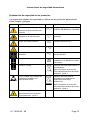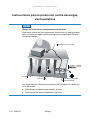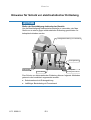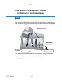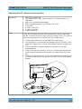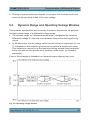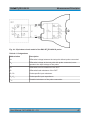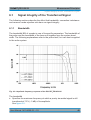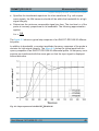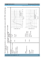
1
® R&S RT‑ZD10/20/30 Active Differential Probe ® R&S RT‑ZA15 External Attenuator User Manual (>:]À2) User Manual Test & Measurement 1410.4550.02 ─ 03 This user manual describes the following R&S®RT-ZD models and external attenuators: ● R&S®RT-ZD10 (1410.4715.02) ● R&S®RT-ZD20 (1410.4409.02) ● R&S®RT-ZD30 (1410.4609.02) ● R&S®RT-ZA15 (1410.4744.02) © 2015 Rohde & Schwarz GmbH & Co. KG Mühldorfstr. 15, 81671 München, Germany Phone: +49 89 41 29 - 0 Fax: +49 89 41 29 12 164 Email: [email protected] Internet: www.rohde-schwarz.com Subject to change – Data without tolerance limits is not binding. R&S® is a registered trademark of Rohde & Schwarz GmbH & Co. KG. Trade names are trademarks of the owners. The following abbreviations are used throughout this manual: R&S®RT-ZD10/20/30 is abbreviated as R&S RT-ZD10/20/30. R&S®RT-ZA15 is abbreviated as R&S RT-ZA15. R&S®ProbeMeter is abbreviated as R&S ProbeMeter. R&S®RTO is abbreviated as R&S RTO. Basic Safety Instructions All plants and locations of the Rohde & Schwarz group of companies make every effort to keep the safety standards of our products up to date and to offer our customers the highest possible degree of safety. Our products and the auxiliary equipment they require are designed, built and tested in accordance with the safety standards that apply in each case. Compliance with these standards is continuously monitored by our quality assurance system. The product described here has been designed, built and tested in accordance with the EC Certificate of Conformity and has left the manufacturer’s plant in a condition fully complying with safety standards. To maintain this condition and to ensure safe operation, you must observe all instructions and warnings provided in this manual. If you have any questions regarding these safety instructions, the Rohde & Schwarz group of companies will be happy to answer them. Furthermore, it is your responsibility to use the product in an appropriate manner. This product is designed for use solely in industrial and laboratory environments or, if expressly permitted, also in the field and must not be used in any way that may cause personal injury or property damage. You are responsible if the product is used for any purpose other than its designated purpose or in disregard of the manufacturer's instructions. The manufacturer shall assume no responsibility for such use of the product. The product is used for its designated purpose if it is used in accordance with its product documentation and within its performance limits (see data sheet, documentation, the following safety instructions). Using the product requires technical skills and, in some cases, a basic knowledge of English. It is therefore essential that only skilled and specialized staff or thoroughly trained personnel with the required skills be allowed to use the product. If personal safety gear is required for using Rohde & Schwarz products, this will be indicated at the appropriate place in the product documentation. Keep the basic safety instructions and the product documentation in a safe place and pass them on to the subsequent users. 1171.0000.52 - 08 Page 1 Basic Safety Instructions Observing the safety instructions will help prevent personal injury or damage of any kind caused by dangerous situations. Therefore, carefully read through and adhere to the following safety instructions before and when using the product. It is also absolutely essential to observe the additional safety instructions on personal safety, for example, that appear in relevant parts of the product documentation. In these safety instructions, the word "product" refers to all merchandise sold and distributed by the Rohde & Schwarz group of companies, including instruments, systems and all accessories. For product-specific information, see the data sheet and the product documentation. Safety labels on products The following safety labels are used on products to warn against risks and dangers. Symbol Meaning Notice, general danger location Symbol Meaning ON/OFF Power Observe product documentation Caution when handling heavy equipment Standby indication Danger of electric shock Direct current (DC) Caution ! Hot surface Alternating current (AC) Protective conductor terminal To identify any terminal which is intended for connection to an external conductor for protection against electric shock in case of a fault, or the terminal of a protective earth Direct/alternating current (DC/AC) Earth (Ground) Class II Equipment to identify equipment meeting the safety requirements specified for Class II equipment (device protected by double or reinforced insulation) Frame or chassis Ground terminal EU labeling for batteries and accumulators. For additional information, see section "Waste disposal/Environmental protection", item 1. 1171.0000.52 - 08 Page 2 Basic Safety Instructions Symbol Meaning Symbol Be careful when handling electrostatic sensitive devices Meaning EU labeling for separate collection of electrical and electronic devices For additional information, see section "Waste disposal/Environmental protection", item 2. Warning! Laser radiation For additional information, see section "Operation", item 7. Signal words and their meaning The following signal words are used in the product documentation in order to warn the reader about risks and dangers. Indicates a hazardous situation which, if not avoided, will result in death or serious injury. Indicates a hazardous situation which, if not avoided, could result in death or serious injury. Indicates a hazardous situation which, if not avoided, could result in minor or moderate injury. Indicates information considered important, but not hazardrelated, e.g. messages relating to property damage. In the product documentation, the word ATTENTION is used synonymously. These signal words are in accordance with the standard definition for civil applications in the European Economic Area. Definitions that deviate from the standard definition may also exist in other economic areas or military applications. It is therefore essential to make sure that the signal words described here are always used only in connection with the related product documentation and the related product. The use of signal words in connection with unrelated products or documentation can result in misinterpretation and in personal injury or material damage. 1171.0000.52 - 08 Page 3 Basic Safety Instructions Operating states and operating positions The product may be operated only under the operating conditions and in the positions specified by the manufacturer, without the product's ventilation being obstructed. If the manufacturer's specifications are not observed, this can result in electric shock, fire and/or serious personal injury or death. Applicable local or national safety regulations and rules for the prevention of accidents must be observed in all work performed. 1. Unless otherwise specified, the following requirements apply to Rohde & Schwarz products: predefined operating position is always with the housing floor facing down, IP protection 2X, use only indoors, max. operating altitude 2000 m above sea level, max. transport altitude 4500 m above sea level. A tolerance of ±10 % shall apply to the nominal voltage and ±5 % to the nominal frequency, overvoltage category 2, pollution degree 2. 2. Do not place the product on surfaces, vehicles, cabinets or tables that for reasons of weight or stability are unsuitable for this purpose. Always follow the manufacturer's installation instructions when installing the product and fastening it to objects or structures (e.g. walls and shelves). An installation that is not carried out as described in the product documentation could result in personal injury or even death. 3. Do not place the product on heat-generating devices such as radiators or fan heaters. The ambient temperature must not exceed the maximum temperature specified in the product documentation or in the data sheet. Product overheating can cause electric shock, fire and/or serious personal injury or even death. Electrical safety If the information on electrical safety is not observed either at all or to the extent necessary, electric shock, fire and/or serious personal injury or death may occur. 1. Prior to switching on the product, always ensure that the nominal voltage setting on the product matches the nominal voltage of the mains-supply network. If a different voltage is to be set, the power fuse of the product may have to be changed accordingly. 2. In the case of products of safety class I with movable power cord and connector, operation is permitted only on sockets with a protective conductor contact and protective conductor. 1171.0000.52 - 08 Page 4 Basic Safety Instructions 3. Intentionally breaking the protective conductor either in the feed line or in the product itself is not permitted. Doing so can result in the danger of an electric shock from the product. If extension cords or connector strips are implemented, they must be checked on a regular basis to ensure that they are safe to use. 4. If there is no power switch for disconnecting the product from the mains, or if the power switch is not suitable for this purpose, use the plug of the connecting cable to disconnect the product from the mains. In such cases, always ensure that the power plug is easily reachable and accessible at all times. For example, if the power plug is the disconnecting device, the length of the connecting cable must not exceed 3 m. Functional or electronic switches are not suitable for providing disconnection from the AC supply network. If products without power switches are integrated into racks or systems, the disconnecting device must be provided at the system level. 5. Never use the product if the power cable is damaged. Check the power cables on a regular basis to ensure that they are in proper operating condition. By taking appropriate safety measures and carefully laying the power cable, ensure that the cable cannot be damaged and that no one can be hurt by, for example, tripping over the cable or suffering an electric shock. 6. The product may be operated only from TN/TT supply networks fuse-protected with max. 16 A (higher fuse only after consulting with the Rohde & Schwarz group of companies). 7. Do not insert the plug into sockets that are dusty or dirty. Insert the plug firmly and all the way into the socket provided for this purpose. Otherwise, sparks that result in fire and/or injuries may occur. 8. Do not overload any sockets, extension cords or connector strips; doing so can cause fire or electric shocks. 9. For measurements in circuits with voltages Vrms > 30 V, suitable measures (e.g. appropriate measuring equipment, fuse protection, current limiting, electrical separation, insulation) should be taken to avoid any hazards. 10. Ensure that the connections with information technology equipment, e.g. PCs or other industrial computers, comply with the IEC 60950-1 / EN 60950-1 or IEC 61010-1 / EN 61010-1 standards that apply in each case. 11. Unless expressly permitted, never remove the cover or any part of the housing while the product is in operation. Doing so will expose circuits and components and can lead to injuries, fire or damage to the product. 1171.0000.52 - 08 Page 5 Basic Safety Instructions 12. If a product is to be permanently installed, the connection between the protective conductor terminal on site and the product's protective conductor must be made first before any other connection is made. The product may be installed and connected only by a licensed electrician. 13. For permanently installed equipment without built-in fuses, circuit breakers or similar protective devices, the supply circuit must be fuse-protected in such a way that anyone who has access to the product, as well as the product itself, is adequately protected from injury or damage. 14. Use suitable overvoltage protection to ensure that no overvoltage (such as that caused by a bolt of lightning) can reach the product. Otherwise, the person operating the product will be exposed to the danger of an electric shock. 15. Any object that is not designed to be placed in the openings of the housing must not be used for this purpose. Doing so can cause short circuits inside the product and/or electric shocks, fire or injuries. 16. Unless specified otherwise, products are not liquid-proof (see also section "Operating states and operating positions", item 1). Therefore, the equipment must be protected against penetration by liquids. If the necessary precautions are not taken, the user may suffer electric shock or the product itself may be damaged, which can also lead to personal injury. 17. Never use the product under conditions in which condensation has formed or can form in or on the product, e.g. if the product has been moved from a cold to a warm environment. Penetration by water increases the risk of electric shock. 18. Prior to cleaning the product, disconnect it completely from the power supply (e.g. AC supply network or battery). Use a soft, non-linting cloth to clean the product. Never use chemical cleaning agents such as alcohol, acetone or diluents for cellulose lacquers. Operation 1. Operating the products requires special training and intense concentration. Make sure that persons who use the products are physically, mentally and emotionally fit enough to do so; otherwise, injuries or material damage may occur. It is the responsibility of the employer/operator to select suitable personnel for operating the products. 2. Before you move or transport the product, read and observe the section titled "Transport". 1171.0000.52 - 08 Page 6 Basic Safety Instructions 3. As with all industrially manufactured goods, the use of substances that induce an allergic reaction (allergens) such as nickel cannot be generally excluded. If you develop an allergic reaction (such as a skin rash, frequent sneezing, red eyes or respiratory difficulties) when using a Rohde & Schwarz product, consult a physician immediately to determine the cause and to prevent health problems or stress. 4. Before you start processing the product mechanically and/or thermally, or before you take it apart, be sure to read and pay special attention to the section titled "Waste disposal/Environmental protection", item 1. 5. Depending on the function, certain products such as RF radio equipment can produce an elevated level of electromagnetic radiation. Considering that unborn babies require increased protection, pregnant women must be protected by appropriate measures. Persons with pacemakers may also be exposed to risks from electromagnetic radiation. The employer/operator must evaluate workplaces where there is a special risk of exposure to radiation and, if necessary, take measures to avert the potential danger. 6. Should a fire occur, the product may release hazardous substances (gases, fluids, etc.) that can cause health problems. Therefore, suitable measures must be taken, e.g. protective masks and protective clothing must be worn. 7. Laser products are given warning labels that are standardized according to their laser class. Lasers can cause biological harm due to the properties of their radiation and due to their extremely concentrated electromagnetic power. If a laser product (e.g. a CD/DVD drive) is integrated into a Rohde & Schwarz product, absolutely no other settings or functions may be used as described in the product documentation. The objective is to prevent personal injury (e.g. due to laser beams). 8. EMC classes (in line with EN 55011/CISPR 11, and analogously with EN 55022/CISPR 22, EN 55032/CISPR 32) Class A equipment: Equipment suitable for use in all environments except residential environments and environments that are directly connected to a lowvoltage supply network that supplies residential buildings Note: Class A equipment is intended for use in an industrial environment. This equipment may cause radio disturbances in residential environments, due to possible conducted as well as radiated disturbances. In this case, the operator may be required to take appropriate measures to eliminate these disturbances. 1171.0000.52 - 08 Page 7 Basic Safety Instructions Class B equipment: Equipment suitable for use in residential environments and environments that are directly connected to a low-voltage supply network that supplies residential buildings Repair and service 1. The product may be opened only by authorized, specially trained personnel. Before any work is performed on the product or before the product is opened, it must be disconnected from the AC supply network. Otherwise, personnel will be exposed to the risk of an electric shock. 2. Adjustments, replacement of parts, maintenance and repair may be performed only by electrical experts authorized by Rohde & Schwarz. Only original parts may be used for replacing parts relevant to safety (e.g. power switches, power transformers, fuses). A safety test must always be performed after parts relevant to safety have been replaced (visual inspection, protective conductor test, insulation resistance measurement, leakage current measurement, functional test). This helps ensure the continued safety of the product. Batteries and rechargeable batteries/cells If the information regarding batteries and rechargeable batteries/cells is not observed either at all or to the extent necessary, product users may be exposed to the risk of explosions, fire and/or serious personal injury, and, in some cases, death. Batteries and rechargeable batteries with alkaline electrolytes (e.g. lithium cells) must be handled in accordance with the EN 62133 standard. 1. Cells must not be taken apart or crushed. 2. Cells or batteries must not be exposed to heat or fire. Storage in direct sunlight must be avoided. Keep cells and batteries clean and dry. Clean soiled connectors using a dry, clean cloth. 3. Cells or batteries must not be short-circuited. Cells or batteries must not be stored in a box or in a drawer where they can short-circuit each other, or where they can be short-circuited by other conductive materials. Cells and batteries must not be removed from their original packaging until they are ready to be used. 4. Cells and batteries must not be exposed to any mechanical shocks that are stronger than permitted. 5. If a cell develops a leak, the fluid must not be allowed to come into contact with the skin or eyes. If contact occurs, wash the affected area with plenty of water and seek medical aid. 1171.0000.52 - 08 Page 8 Basic Safety Instructions 6. Improperly replacing or charging cells or batteries that contain alkaline electrolytes (e.g. lithium cells) can cause explosions. Replace cells or batteries only with the matching Rohde & Schwarz type (see parts list) in order to ensure the safety of the product. 7. Cells and batteries must be recycled and kept separate from residual waste. Rechargeable batteries and normal batteries that contain lead, mercury or cadmium are hazardous waste. Observe the national regulations regarding waste disposal and recycling. Transport 1. The product may be very heavy. Therefore, the product must be handled with care. In some cases, the user may require a suitable means of lifting or moving the product (e.g. with a lift-truck) to avoid back or other physical injuries. 2. Handles on the products are designed exclusively to enable personnel to transport the product. It is therefore not permissible to use handles to fasten the product to or on transport equipment such as cranes, fork lifts, wagons, etc. The user is responsible for securely fastening the products to or on the means of transport or lifting. Observe the safety regulations of the manufacturer of the means of transport or lifting. Noncompliance can result in personal injury or material damage. 3. If you use the product in a vehicle, it is the sole responsibility of the driver to drive the vehicle safely and properly. The manufacturer assumes no responsibility for accidents or collisions. Never use the product in a moving vehicle if doing so could distract the driver of the vehicle. Adequately secure the product in the vehicle to prevent injuries or other damage in the event of an accident. Waste disposal/Environmental protection 1. Specially marked equipment has a battery or accumulator that must not be disposed of with unsorted municipal waste, but must be collected separately. It may only be disposed of at a suitable collection point or via a Rohde & Schwarz customer service center. 2. Waste electrical and electronic equipment must not be disposed of with unsorted municipal waste, but must be collected separately. Rohde & Schwarz GmbH & Co. KG has developed a disposal concept and takes full responsibility for take-back obligations and disposal obligations for manufacturers within the EU. Contact your Rohde & Schwarz customer service center for environmentally responsible disposal of the product. 1171.0000.52 - 08 Page 9 Instrucciones de seguridad elementales 3. If products or their components are mechanically and/or thermally processed in a manner that goes beyond their intended use, hazardous substances (heavy-metal dust such as lead, beryllium, nickel) may be released. For this reason, the product may only be disassembled by specially trained personnel. Improper disassembly may be hazardous to your health. National waste disposal regulations must be observed. 4. If handling the product releases hazardous substances or fuels that must be disposed of in a special way, e.g. coolants or engine oils that must be replenished regularly, the safety instructions of the manufacturer of the hazardous substances or fuels and the applicable regional waste disposal regulations must be observed. Also observe the relevant safety instructions in the product documentation. The improper disposal of hazardous substances or fuels can cause health problems and lead to environmental damage. For additional information about environmental protection, visit the Rohde & Schwarz website. Instrucciones de seguridad elementales ¡Es imprescindible leer y cumplir las siguientes instrucciones e informaciones de seguridad! El principio del grupo de empresas Rohde & Schwarz consiste en tener nuestros productos siempre al día con los estándares de seguridad y de ofrecer a nuestros clientes el máximo grado de seguridad. Nuestros productos y todos los equipos adicionales son siempre fabricados y examinados según las normas de seguridad vigentes. Nuestro sistema de garantía de calidad controla constantemente que sean cumplidas estas normas. El presente producto ha sido fabricado y examinado según el certificado de conformidad de la UE y ha salido de nuestra planta en estado impecable según los estándares técnicos de seguridad. Para poder preservar este estado y garantizar un funcionamiento libre de peligros, el usuario deberá atenerse a todas las indicaciones, informaciones de seguridad y notas de alerta. El grupo de empresas Rohde & Schwarz está siempre a su disposición en caso de que tengan preguntas referentes a estas informaciones de seguridad. 1171.0000.52 - 08 Page 10 Instrucciones de seguridad elementales Además queda en la responsabilidad del usuario utilizar el producto en la forma debida. Este producto está destinado exclusivamente al uso en la industria y el laboratorio o, si ha sido expresamente autorizado, para aplicaciones de campo y de ninguna manera deberá ser utilizado de modo que alguna persona/cosa pueda sufrir daño. El uso del producto fuera de sus fines definidos o sin tener en cuenta las instrucciones del fabricante queda en la responsabilidad del usuario. El fabricante no se hace en ninguna forma responsable de consecuencias a causa del mal uso del producto. Se parte del uso correcto del producto para los fines definidos si el producto es utilizado conforme a las indicaciones de la correspondiente documentación del producto y dentro del margen de rendimiento definido (ver hoja de datos, documentación, informaciones de seguridad que siguen). El uso del producto hace necesarios conocimientos técnicos y ciertos conocimientos del idioma inglés. Por eso se debe tener en cuenta que el producto solo pueda ser operado por personal especializado o personas instruidas en profundidad con las capacidades correspondientes. Si fuera necesaria indumentaria de seguridad para el uso de productos de Rohde & Schwarz, encontraría la información debida en la documentación del producto en el capítulo correspondiente. Guarde bien las informaciones de seguridad elementales, así como la documentación del producto, y entréguelas a usuarios posteriores. Tener en cuenta las informaciones de seguridad sirve para evitar en lo posible lesiones o daños por peligros de toda clase. Por eso es imprescindible leer detalladamente y comprender por completo las siguientes informaciones de seguridad antes de usar el producto, y respetarlas durante el uso del producto. Deberán tenerse en cuenta todas las demás informaciones de seguridad, como p. ej. las referentes a la protección de personas, que encontrarán en el capítulo correspondiente de la documentación del producto y que también son de obligado cumplimiento. En las presentes informaciones de seguridad se recogen todos los objetos que distribuye el grupo de empresas Rohde & Schwarz bajo la denominación de "producto", entre ellos también aparatos, instalaciones así como toda clase de accesorios. Los datos específicos del producto figuran en la hoja de datos y en la documentación del producto. 1171.0000.52 - 08 Page 11 Instrucciones de seguridad elementales Señalización de seguridad de los productos Las siguientes señales de seguridad se utilizan en los productos para advertir sobre riesgos y peligros. Símbolo Significado Aviso: punto de peligro general Observar la documentación del producto Símbolo Significado Tensión de alimentación de PUESTA EN MARCHA / PARADA Atención en el manejo de dispositivos de peso elevado Indicación de estado de espera (standby) Peligro de choque eléctrico Corriente continua (DC) Advertencia: superficie caliente Corriente alterna (AC) Conexión a conductor de protección Corriente continua / Corriente alterna (DC/AC) Conexión a tierra El aparato está protegido en su totalidad por un aislamiento doble (reforzado) Conexión a masa Distintivo de la UE para baterías y acumuladores Más información en la sección "Eliminación/protección del medio ambiente", punto 1. Aviso: Cuidado en el manejo de dispositivos sensibles a la electrostática (ESD) Distintivo de la UE para la eliminación por separado de dispositivos eléctricos y electrónicos Más información en la sección "Eliminación/protección del medio ambiente", punto 2. Advertencia: rayo láser Más información en la sección "Funcionamiento", punto 7. 1171.0000.52 - 08 Page 12 Instrucciones de seguridad elementales Palabras de señal y su significado En la documentación del producto se utilizan las siguientes palabras de señal con el fin de advertir contra riesgos y peligros. Indica una situación de peligro que, si no se evita, causa lesiones graves o incluso la muerte. Indica una situación de peligro que, si no se evita, puede causar lesiones graves o incluso la muerte. Indica una situación de peligro que, si no se evita, puede causar lesiones leves o moderadas. Indica información que se considera importante, pero no en relación con situaciones de peligro; p. ej., avisos sobre posibles daños materiales. En la documentación del producto se emplea de forma sinónima el término CUIDADO. Las palabras de señal corresponden a la definición habitual para aplicaciones civiles en el área económica europea. Pueden existir definiciones diferentes a esta definición en otras áreas económicas o en aplicaciones militares. Por eso se deberá tener en cuenta que las palabras de señal aquí descritas sean utilizadas siempre solamente en combinación con la correspondiente documentación del producto y solamente en combinación con el producto correspondiente. La utilización de las palabras de señal en combinación con productos o documentaciones que no les correspondan puede llevar a interpretaciones equivocadas y tener por consecuencia daños en personas u objetos. 1171.0000.52 - 08 Page 13 Instrucciones de seguridad elementales Estados operativos y posiciones de funcionamiento El producto solamente debe ser utilizado según lo indicado por el fabricante respecto a los estados operativos y posiciones de funcionamiento sin que se obstruya la ventilación. Si no se siguen las indicaciones del fabricante, pueden producirse choques eléctricos, incendios y/o lesiones graves con posible consecuencia de muerte. En todos los trabajos deberán ser tenidas en cuenta las normas nacionales y locales de seguridad del trabajo y de prevención de accidentes. 1. Si no se convino de otra manera, es para los productos Rohde & Schwarz válido lo que sigue: como posición de funcionamiento se define por principio la posición con el suelo de la caja para abajo, modo de protección IP 2X, uso solamente en estancias interiores, utilización hasta 2000 m sobre el nivel del mar, transporte hasta 4500 m sobre el nivel del mar. Se aplicará una tolerancia de ±10 % sobre el voltaje nominal y de ±5 % sobre la frecuencia nominal. Categoría de sobrecarga eléctrica 2, índice de suciedad 2. 2. No sitúe el producto encima de superficies, vehículos, estantes o mesas, que por sus características de peso o de estabilidad no sean aptos para él. Siga siempre las instrucciones de instalación del fabricante cuando instale y asegure el producto en objetos o estructuras (p. ej. paredes y estantes). Si se realiza la instalación de modo distinto al indicado en la documentación del producto, se pueden causar lesiones o, en determinadas circunstancias, incluso la muerte. 3. No ponga el producto sobre aparatos que generen calor (p. ej. radiadores o calefactores). La temperatura ambiente no debe superar la temperatura máxima especificada en la documentación del producto o en la hoja de datos. En caso de sobrecalentamiento del producto, pueden producirse choques eléctricos, incendios y/o lesiones graves con posible consecuencia de muerte. Seguridad eléctrica Si no se siguen (o se siguen de modo insuficiente) las indicaciones del fabricante en cuanto a seguridad eléctrica, pueden producirse choques eléctricos, incendios y/o lesiones graves con posible consecuencia de muerte. 1. Antes de la puesta en marcha del producto se deberá comprobar siempre que la tensión preseleccionada en el producto coincida con la de la red de alimentación eléctrica. Si es necesario modificar el ajuste de tensión, también se deberán cambiar en caso dado los fusibles correspondientes del producto. 1171.0000.52 - 08 Page 14 Instrucciones de seguridad elementales 2. Los productos de la clase de protección I con alimentación móvil y enchufe individual solamente podrán enchufarse a tomas de corriente con contacto de seguridad y con conductor de protección conectado. 3. Queda prohibida la interrupción intencionada del conductor de protección, tanto en la toma de corriente como en el mismo producto. La interrupción puede tener como consecuencia el riesgo de que el producto sea fuente de choques eléctricos. Si se utilizan cables alargadores o regletas de enchufe, deberá garantizarse la realización de un examen regular de los mismos en cuanto a su estado técnico de seguridad. 4. Si el producto no está equipado con un interruptor para desconectarlo de la red, o bien si el interruptor existente no resulta apropiado para la desconexión de la red, el enchufe del cable de conexión se deberá considerar como un dispositivo de desconexión. El dispositivo de desconexión se debe poder alcanzar fácilmente y debe estar siempre bien accesible. Si, p. ej., el enchufe de conexión a la red es el dispositivo de desconexión, la longitud del cable de conexión no debe superar 3 m). Los interruptores selectores o electrónicos no son aptos para el corte de la red eléctrica. Si se integran productos sin interruptor en bastidores o instalaciones, se deberá colocar el interruptor en el nivel de la instalación. 5. No utilice nunca el producto si está dañado el cable de conexión a red. Compruebe regularmente el correcto estado de los cables de conexión a red. Asegúrese, mediante las medidas de protección y de instalación adecuadas, de que el cable de conexión a red no pueda ser dañado o de que nadie pueda ser dañado por él, p. ej. al tropezar o por un choque eléctrico. 6. Solamente está permitido el funcionamiento en redes de alimentación TN/TT aseguradas con fusibles de 16 A como máximo (utilización de fusibles de mayor amperaje solo previa consulta con el grupo de empresas Rohde & Schwarz). 7. Nunca conecte el enchufe en tomas de corriente sucias o llenas de polvo. Introduzca el enchufe por completo y fuertemente en la toma de corriente. La no observación de estas medidas puede provocar chispas, fuego y/o lesiones. 8. No sobrecargue las tomas de corriente, los cables alargadores o las regletas de enchufe ya que esto podría causar fuego o choques eléctricos. 9. En las mediciones en circuitos de corriente con una tensión Ueff > 30 V se deberán tomar las medidas apropiadas para impedir cualquier peligro (p. ej. medios de medición adecuados, seguros, limitación de tensión, corte protector, aislamiento etc.). 1171.0000.52 - 08 Page 15 Instrucciones de seguridad elementales 10. Para la conexión con dispositivos informáticos como un PC o un ordenador industrial, debe comprobarse que éstos cumplan los estándares IEC609501/EN60950-1 o IEC61010-1/EN 61010-1 válidos en cada caso. 11. A menos que esté permitido expresamente, no retire nunca la tapa ni componentes de la carcasa mientras el producto esté en servicio. Esto pone a descubierto los cables y componentes eléctricos y puede causar lesiones, fuego o daños en el producto. 12. Si un producto se instala en un lugar fijo, se deberá primero conectar el conductor de protección fijo con el conductor de protección del producto antes de hacer cualquier otra conexión. La instalación y la conexión deberán ser efectuadas por un electricista especializado. 13. En el caso de dispositivos fijos que no estén provistos de fusibles, interruptor automático ni otros mecanismos de seguridad similares, el circuito de alimentación debe estar protegido de modo que todas las personas que puedan acceder al producto, así como el producto mismo, estén a salvo de posibles daños. 14. Todo producto debe estar protegido contra sobretensión (debida p. ej. a una caída del rayo) mediante los correspondientes sistemas de protección. Si no, el personal que lo utilice quedará expuesto al peligro de choque eléctrico. 15. No debe introducirse en los orificios de la caja del aparato ningún objeto que no esté destinado a ello. Esto puede producir cortocircuitos en el producto y/o puede causar choques eléctricos, fuego o lesiones. 16. Salvo indicación contraria, los productos no están impermeabilizados (ver también el capítulo "Estados operativos y posiciones de funcionamiento", punto 1). Por eso es necesario tomar las medidas necesarias para evitar la entrada de líquidos. En caso contrario, existe peligro de choque eléctrico para el usuario o de daños en el producto, que también pueden redundar en peligro para las personas. 17. No utilice el producto en condiciones en las que pueda producirse o ya se hayan producido condensaciones sobre el producto o en el interior de éste, como p. ej. al desplazarlo de un lugar frío a otro caliente. La entrada de agua aumenta el riesgo de choque eléctrico. 18. Antes de la limpieza, desconecte por completo el producto de la alimentación de tensión (p. ej. red de alimentación o batería). Realice la limpieza de los aparatos con un paño suave, que no se deshilache. No utilice bajo ningún concepto productos de limpieza químicos como alcohol, acetona o diluyentes para lacas nitrocelulósicas. 1171.0000.52 - 08 Page 16 Instrucciones de seguridad elementales Funcionamiento 1. El uso del producto requiere instrucciones especiales y una alta concentración durante el manejo. Debe asegurarse que las personas que manejen el producto estén a la altura de los requerimientos necesarios en cuanto a aptitudes físicas, psíquicas y emocionales, ya que de otra manera no se pueden excluir lesiones o daños de objetos. El empresario u operador es responsable de seleccionar el personal usuario apto para el manejo del producto. 2. Antes de desplazar o transportar el producto, lea y tenga en cuenta el capítulo "Transporte". 3. Como con todo producto de fabricación industrial no puede quedar excluida en general la posibilidad de que se produzcan alergias provocadas por algunos materiales empleados ―los llamados alérgenos (p. ej. el níquel)―. Si durante el manejo de productos Rohde & Schwarz se producen reacciones alérgicas, como p. ej. irritaciones cutáneas, estornudos continuos, enrojecimiento de la conjuntiva o dificultades respiratorias, debe avisarse inmediatamente a un médico para investigar las causas y evitar cualquier molestia o daño a la salud. 4. Antes de la manipulación mecánica y/o térmica o el desmontaje del producto, debe tenerse en cuenta imprescindiblemente el capítulo "Eliminación/protección del medio ambiente", punto 1. 5. Ciertos productos, como p. ej. las instalaciones de radiocomunicación RF, pueden a causa de su función natural, emitir una radiación electromagnética aumentada. Deben tomarse todas las medidas necesarias para la protección de las mujeres embarazadas. También las personas con marcapasos pueden correr peligro a causa de la radiación electromagnética. El empresario/operador tiene la obligación de evaluar y señalizar las áreas de trabajo en las que exista un riesgo elevado de exposición a radiaciones. 6. Tenga en cuenta que en caso de incendio pueden desprenderse del producto sustancias tóxicas (gases, líquidos etc.) que pueden generar daños a la salud. Por eso, en caso de incendio deben usarse medidas adecuadas, como p. ej. máscaras antigás e indumentaria de protección. 1171.0000.52 - 08 Page 17 Instrucciones de seguridad elementales 7. Los productos con láser están provistos de indicaciones de advertencia normalizadas en función de la clase de láser del que se trate. Los rayos láser pueden provocar daños de tipo biológico a causa de las propiedades de su radiación y debido a su concentración extrema de potencia electromagnética. En caso de que un producto Rohde & Schwarz contenga un producto láser (p. ej. un lector de CD/DVD), no debe usarse ninguna otra configuración o función aparte de las descritas en la documentación del producto, a fin de evitar lesiones (p. ej. debidas a irradiación láser). 8. Clases de compatibilidad electromagnética (conforme a EN 55011 / CISPR 11; y en analogía con EN 55022 / CISPR 22, EN 55032 / CISPR 32) Aparato de clase A: Aparato adecuado para su uso en todos los entornos excepto en los residenciales y en aquellos conectados directamente a una red de distribución de baja tensión que suministra corriente a edificios residenciales. Nota: Los aparatos de clase A están destinados al uso en entornos industriales. Estos aparatos pueden causar perturbaciones radioeléctricas en entornos residenciales debido a posibles perturbaciones guiadas o radiadas. En este caso, se le podrá solicitar al operador que tome las medidas adecuadas para eliminar estas perturbaciones. Aparato de clase B: Aparato adecuado para su uso en entornos residenciales, así como en aquellos conectados directamente a una red de distribución de baja tensión que suministra corriente a edificios residenciales. Reparación y mantenimiento 1. El producto solamente debe ser abierto por personal especializado con autorización para ello. Antes de manipular el producto o abrirlo, es obligatorio desconectarlo de la tensión de alimentación, para evitar toda posibilidad de choque eléctrico. 2. El ajuste, el cambio de partes, el mantenimiento y la reparación deberán ser efectuadas solamente por electricistas autorizados por Rohde & Schwarz. Si se reponen partes con importancia para los aspectos de seguridad (p. ej. el enchufe, los transformadores o los fusibles), solamente podrán ser sustituidos por partes originales. Después de cada cambio de partes relevantes para la seguridad deberá realizarse un control de seguridad (control a primera vista, control del conductor de protección, medición de resistencia de aislamiento, medición de la corriente de fuga, control de funcionamiento). Con esto queda garantizada la seguridad del producto. 1171.0000.52 - 08 Page 18 Instrucciones de seguridad elementales Baterías y acumuladores o celdas Si no se siguen (o se siguen de modo insuficiente) las indicaciones en cuanto a las baterías y acumuladores o celdas, pueden producirse explosiones, incendios y/o lesiones graves con posible consecuencia de muerte. El manejo de baterías y acumuladores con electrolitos alcalinos (p. ej. celdas de litio) debe seguir el estándar EN 62133. 1. No deben desmontarse, abrirse ni triturarse las celdas. 2. Las celdas o baterías no deben someterse a calor ni fuego. Debe evitarse el almacenamiento a la luz directa del sol. Las celdas y baterías deben mantenerse limpias y secas. Limpiar las conexiones sucias con un paño seco y limpio. 3. Las celdas o baterías no deben cortocircuitarse. Es peligroso almacenar las celdas o baterías en estuches o cajones en cuyo interior puedan cortocircuitarse por contacto recíproco o por contacto con otros materiales conductores. No deben extraerse las celdas o baterías de sus embalajes originales hasta el momento en que vayan a utilizarse. 4. Las celdas o baterías no deben someterse a impactos mecánicos fuertes indebidos. 5. En caso de falta de estanqueidad de una celda, el líquido vertido no debe entrar en contacto con la piel ni los ojos. Si se produce contacto, lavar con agua abundante la zona afectada y avisar a un médico. 6. En caso de cambio o recarga inadecuados, las celdas o baterías que contienen electrolitos alcalinos (p. ej. las celdas de litio) pueden explotar. Para garantizar la seguridad del producto, las celdas o baterías solo deben ser sustituidas por el tipo Rohde & Schwarz correspondiente (ver lista de recambios). 7. Las baterías y celdas deben reciclarse y no deben tirarse a la basura doméstica. Las baterías o acumuladores que contienen plomo, mercurio o cadmio deben tratarse como residuos especiales. Respete en esta relación las normas nacionales de eliminación y reciclaje. Transporte 1. El producto puede tener un peso elevado. Por eso es necesario desplazarlo o transportarlo con precaución y, si es necesario, usando un sistema de elevación adecuado (p. ej. una carretilla elevadora), a fin de evitar lesiones en la espalda u otros daños personales. 1171.0000.52 - 08 Page 19 Instrucciones de seguridad elementales 2. Las asas instaladas en los productos sirven solamente de ayuda para el transporte del producto por personas. Por eso no está permitido utilizar las asas para la sujeción en o sobre medios de transporte como p. ej. grúas, carretillas elevadoras de horquilla, carros etc. Es responsabilidad suya fijar los productos de manera segura a los medios de transporte o elevación. Para evitar daños personales o daños en el producto, siga las instrucciones de seguridad del fabricante del medio de transporte o elevación utilizado. 3. Si se utiliza el producto dentro de un vehículo, recae de manera exclusiva en el conductor la responsabilidad de conducir el vehículo de manera segura y adecuada. El fabricante no asumirá ninguna responsabilidad por accidentes o colisiones. No utilice nunca el producto dentro de un vehículo en movimiento si esto pudiera distraer al conductor. Asegure el producto dentro del vehículo debidamente para evitar, en caso de un accidente, lesiones u otra clase de daños. Eliminación/protección del medio ambiente 1. Los dispositivos marcados contienen una batería o un acumulador que no se debe desechar con los residuos domésticos sin clasificar, sino que debe ser recogido por separado. La eliminación se debe efectuar exclusivamente a través de un punto de recogida apropiado o del servicio de atención al cliente de Rohde & Schwarz. 2. Los dispositivos eléctricos usados no se deben desechar con los residuos domésticos sin clasificar, sino que deben ser recogidos por separado. Rohde & Schwarz GmbH & Co.KG ha elaborado un concepto de eliminación de residuos y asume plenamente los deberes de recogida y eliminación para los fabricantes dentro de la UE. Para desechar el producto de manera respetuosa con el medio ambiente, diríjase a su servicio de atención al cliente de Rohde & Schwarz. 3. Si se trabaja de manera mecánica y/o térmica cualquier producto o componente más allá del funcionamiento previsto, pueden liberarse sustancias peligrosas (polvos con contenido de metales pesados como p. ej. plomo, berilio o níquel). Por eso el producto solo debe ser desmontado por personal especializado con formación adecuada. Un desmontaje inadecuado puede ocasionar daños para la salud. Se deben tener en cuenta las directivas nacionales referentes a la eliminación de residuos. 1171.0000.52 - 08 Page 20 Instrucciones de seguridad elementales 4. En caso de que durante el trato del producto se formen sustancias peligrosas o combustibles que deban tratarse como residuos especiales (p. ej. refrigerantes o aceites de motor con intervalos de cambio definidos), deben tenerse en cuenta las indicaciones de seguridad del fabricante de dichas sustancias y las normas regionales de eliminación de residuos. Tenga en cuenta también en caso necesario las indicaciones de seguridad especiales contenidas en la documentación del producto. La eliminación incorrecta de sustancias peligrosas o combustibles puede causar daños a la salud o daños al medio ambiente. Se puede encontrar más información sobre la protección del medio ambiente en la página web de Rohde & Schwarz. 1171.0000.52 - 08 Page 21 Grundlegende Sicherheitshinweise Lesen und beachten Sie unbedingt die nachfolgenden Anweisungen und Sicherheitshinweise! Alle Werke und Standorte der Rohde & Schwarz Firmengruppe sind ständig bemüht, den Sicherheitsstandard unserer Produkte auf dem aktuellsten Stand zu halten und unseren Kunden ein höchstmögliches Maß an Sicherheit zu bieten. Unsere Produkte und die dafür erforderlichen Zusatzgeräte werden entsprechend der jeweils gültigen Sicherheitsvorschriften gebaut und geprüft. Die Einhaltung dieser Bestimmungen wird durch unser Qualitätssicherungssystem laufend überwacht. Das vorliegende Produkt ist gemäß beiliegender EUKonformitätsbescheinigung gebaut und geprüft und hat das Werk in sicherheitstechnisch einwandfreiem Zustand verlassen. Um diesen Zustand zu erhalten und einen gefahrlosen Betrieb sicherzustellen, muss der Benutzer alle Hinweise, Warnhinweise und Warnvermerke beachten. Bei allen Fragen bezüglich vorliegender Sicherheitshinweise steht Ihnen die Rohde & Schwarz Firmengruppe jederzeit gerne zur Verfügung. Darüber hinaus liegt es in der Verantwortung des Benutzers, das Produkt in geeigneter Weise zu verwenden. Das Produkt ist ausschließlich für den Betrieb in Industrie und Labor bzw., wenn ausdrücklich zugelassen, auch für den Feldeinsatz bestimmt und darf in keiner Weise so verwendet werden, dass einer Person/Sache Schaden zugefügt werden kann. Die Benutzung des Produkts außerhalb des bestimmungsgemäßen Gebrauchs oder unter Missachtung der Anweisungen des Herstellers liegt in der Verantwortung des Benutzers. Der Hersteller übernimmt keine Verantwortung für die Zweckentfremdung des Produkts. Die bestimmungsgemäße Verwendung des Produkts wird angenommen, wenn das Produkt nach den Vorgaben der zugehörigen Produktdokumentation innerhalb seiner Leistungsgrenzen verwendet wird (siehe Datenblatt, Dokumentation, nachfolgende Sicherheitshinweise). Die Benutzung des Produkts erfordert Fachkenntnisse und zum Teil englische Sprachkenntnisse. Es ist daher zu beachten, dass das Produkt ausschließlich von Fachkräften oder sorgfältig eingewiesenen Personen mit entsprechenden Fähigkeiten bedient werden darf. Sollte für die Verwendung von Rohde & Schwarz-Produkten persönliche Schutzausrüstung erforderlich sein, wird in der Produktdokumentation an entsprechender Stelle darauf hingewiesen. Bewahren Sie die grundlegenden Sicherheitshinweise und die Produktdokumentation gut auf und geben Sie diese an weitere Benutzer des Produkts weiter. 1171.0000.51 – 08 Seite 1 Grundlegende Sicherheitshinweise Die Einhaltung der Sicherheitshinweise dient dazu, Verletzungen oder Schäden durch Gefahren aller Art auszuschließen. Hierzu ist es erforderlich, dass die nachstehenden Sicherheitshinweise vor der Benutzung des Produkts sorgfältig gelesen und verstanden sowie bei der Benutzung des Produkts beachtet werden. Sämtliche weitere Sicherheitshinweise wie z.B. zum Personenschutz, die an entsprechender Stelle der Produktdokumentation stehen, sind ebenfalls unbedingt zu beachten. In den vorliegenden Sicherheitshinweisen sind sämtliche von der Rohde & Schwarz Firmengruppe vertriebenen Waren unter dem Begriff „Produkt“ zusammengefasst, hierzu zählen u. a. Geräte, Anlagen sowie sämtliches Zubehör. Symbole und Sicherheitskennzeichnungen Symbol Bedeutung Achtung, allgemeine Gefahrenstelle Symbol Bedeutung EIN-/AUS (Versorgung) Produktdokumentation beachten Vorsicht beim Umgang mit Geräten mit hohem Gewicht Stand-by-Anzeige Gefahr vor elektrischem Schlag Gleichstrom (DC) Warnung vor heißer Oberfläche Wechselstrom (AC) Schutzleiteranschluss Gleichstrom/Wechselstrom (DC/AC) Erdungsanschluss Gerät entspricht den Sicherheitsanforderungen an die Schutzklasse II (Gerät durchgehend durch doppelte / verstärkte Isolierung geschützt. Masseanschluss des Gestells oder Gehäuses EU - Kennzeichnung für Batterien und Akkumulatoren. Das Gerät enthält eine Batterie bzw. einen Akkumulator. Diese dürfen nicht über unsortierten Siedlungsabfall entsorgt werden, sondern sollten getrennt gesammelt werden. Weitere Informationen siehe Seite 11. 1171.0000.51 – 08 Seite 2 Grundlegende Sicherheitshinweise Symbol Bedeutung Achtung beim Umgang mit elektrostatisch gefährdeten Bauelementen Symbol Bedeutung EU - Kennzeichnung für die getrennte Sammlung von Elektround Elektronikgeräten. Elektroaltgeräte dürfen nicht über unsortierten Siedlungsabfall entsorgt werden, sondern müssen getrennt gesammelt werden. Weitere Informationen siehe Seite 11. Warnung vor Laserstrahl Produkte mit Laser sind je nach ihrer Laser-Klasse mit genormten Warnhinweisen versehen. Laser können aufgrund der Eigenschaften ihrer Strahlung und aufgrund ihrer extrem konzentrierten elektromagnetischen Leistung biologische Schäden verursachen. Für zusätzliche Informationen siehe Kapitel „Betrieb“ Punkt 7. 1171.0000.51 – 08 Seite 3 Grundlegende Sicherheitshinweise Signalworte und ihre Bedeutung Die folgenden Signalworte werden in der Produktdokumentation verwendet, um vor Risiken und Gefahren zu warnen. kennzeichnet eine unmittelbare Gefährdung mit hohem Risiko, die Tod oder schwere Körperverletzung zur Folge haben wird, wenn sie nicht vermieden wird. kennzeichnet eine mögliche Gefährdung mit mittlerem Risiko, die Tod oder (schwere) Körperverletzung zur Folge haben kann, wenn sie nicht vermieden wird. kennzeichnet eine Gefährdung mit geringem Risiko, die leichte oder mittlere Körperverletzungen zur Folge haben könnte, wenn sie nicht vermieden wird. weist auf die Möglichkeit einer Fehlbedienung hin, bei der das Produkt Schaden nehmen kann. Diese Signalworte entsprechen der im europäischen Wirtschaftsraum üblichen Definition für zivile Anwendungen. Neben dieser Definition können in anderen Wirtschaftsräumen oder bei militärischen Anwendungen abweichende Definitionen existieren. Es ist daher darauf zu achten, dass die hier beschriebenen Signalworte stets nur in Verbindung mit der zugehörigen Produktdokumentation und nur in Verbindung mit dem zugehörigen Produkt verwendet werden. Die Verwendung von Signalworten in Zusammenhang mit nicht zugehörigen Produkten oder nicht zugehörigen Dokumentationen kann zu Fehlinterpretationen führen und damit zu Personen- oder Sachschäden führen. Betriebszustände und Betriebslagen Das Produkt darf nur in den vom Hersteller angegebenen Betriebszuständen und Betriebslagen ohne Behinderung der Belüftung betrieben werden. Werden die Herstellerangaben nicht eingehalten, kann dies elektrischen Schlag, Brand und/oder schwere Verletzungen von Personen, unter Umständen mit Todesfolge, verursachen. Bei allen Arbeiten sind die örtlichen bzw. landesspezifischen Sicherheits- und Unfallverhütungsvorschriften zu beachten. 1. Sofern nicht anders vereinbart, gilt für R&S-Produkte folgendes: als vorgeschriebene Betriebslage grundsätzlich Gehäuseboden unten, IPSchutzart 2X, Verschmutzungsgrad 2, Überspannungskategorie 2, nur in Innenräumen verwenden, Betrieb bis 2000 m ü. NN, Transport bis 4500 m ü. NN, für die Nennspannung gilt eine Toleranz von ±10%, für die Nennfrequenz eine Toleranz von ±5%. 1171.0000.51 – 08 Seite 4 Grundlegende Sicherheitshinweise 2. Stellen Sie das Produkt nicht auf Oberflächen, Fahrzeuge, Ablagen oder Tische, die aus Gewichts- oder Stabilitätsgründen nicht dafür geeignet sind. Folgen Sie bei Aufbau und Befestigung des Produkts an Gegenständen oder Strukturen (z.B. Wände und Regale) immer den Installationshinweisen des Herstellers. Bei Installation abweichend von der Produktdokumentation können Personen verletzt, unter Umständen sogar getötet werden. 3. Stellen Sie das Produkt nicht auf hitzeerzeugende Gerätschaften (z.B. Radiatoren und Heizlüfter). Die Umgebungstemperatur darf nicht die in der Produktdokumentation oder im Datenblatt spezifizierte Maximaltemperatur überschreiten. Eine Überhitzung des Produkts kann elektrischen Schlag, Brand und/oder schwere Verletzungen von Personen, unter Umständen mit Todesfolge, verursachen. Elektrische Sicherheit Werden die Hinweise zur elektrischen Sicherheit nicht oder unzureichend beachtet, kann dies elektrischen Schlag, Brand und/oder schwere Verletzungen von Personen, unter Umständen mit Todesfolge, verursachen. 1. Vor jedem Einschalten des Produkts ist sicherzustellen, dass die am Produkt eingestellte Nennspannung und die Netznennspannung des Versorgungsnetzes übereinstimmen. Ist es erforderlich, die Spannungseinstellung zu ändern, so muss ggf. auch die dazu gehörige Netzsicherung des Produkts geändert werden. 2. Bei Produkten der Schutzklasse I mit beweglicher Netzzuleitung und Gerätesteckvorrichtung ist der Betrieb nur an Steckdosen mit Schutzkontakt und angeschlossenem Schutzleiter zulässig. 3. Jegliche absichtliche Unterbrechung des Schutzleiters, sowohl in der Zuleitung als auch am Produkt selbst, ist unzulässig. Es kann dazu führen, dass von dem Produkt die Gefahr eines elektrischen Schlags ausgeht. Bei Verwendung von Verlängerungsleitungen oder Steckdosenleisten ist sicherzustellen, dass diese regelmäßig auf ihren sicherheitstechnischen Zustand überprüft werden. 1171.0000.51 – 08 Seite 5 Grundlegende Sicherheitshinweise 4. Sofern das Produkt nicht mit einem Netzschalter zur Netztrennung ausgerüstet ist, beziehungsweise der vorhandene Netzschalter zu Netztrennung nicht geeignet ist, so ist der Stecker des Anschlusskabels als Trennvorrichtung anzusehen. Die Trennvorrichtung muss jederzeit leicht erreichbar und gut zugänglich sein. Ist z.B. der Netzstecker die Trennvorrichtung, darf die Länge des Anschlusskabels 3 m nicht überschreiten. Funktionsschalter oder elektronische Schalter sind zur Netztrennung nicht geeignet. Werden Produkte ohne Netzschalter in Gestelle oder Anlagen integriert, so ist die Trennvorrichtung auf Anlagenebene zu verlagern. 5. Benutzen Sie das Produkt niemals, wenn das Netzkabel beschädigt ist. Überprüfen Sie regelmäßig den einwandfreien Zustand der Netzkabel. Stellen Sie durch geeignete Schutzmaßnahmen und Verlegearten sicher, dass das Netzkabel nicht beschädigt werden kann und niemand z.B. durch Stolperfallen oder elektrischen Schlag zu Schaden kommen kann. 6. Der Betrieb ist nur an TN/TT Versorgungsnetzen gestattet, die mit höchstens 16 A abgesichert sind (höhere Absicherung nur nach Rücksprache mit der Rohde & Schwarz Firmengruppe). 7. Stecken Sie den Stecker nicht in verstaubte oder verschmutzte Steckdosen/buchsen. Stecken Sie die Steckverbindung/-vorrichtung fest und vollständig in die dafür vorgesehenen Steckdosen/-buchsen. Missachtung dieser Maßnahmen kann zu Funken, Feuer und/oder Verletzungen führen. 8. Überlasten Sie keine Steckdosen, Verlängerungskabel oder Steckdosenleisten, dies kann Feuer oder elektrische Schläge verursachen. 9. Bei Messungen in Stromkreisen mit Spannungen Ueff > 30 V ist mit geeigneten Maßnahmen Vorsorge zu treffen, dass jegliche Gefährdung ausgeschlossen wird (z.B. geeignete Messmittel, Absicherung, Strombegrenzung, Schutztrennung, Isolierung usw.). 10. Bei Verbindungen mit informationstechnischen Geräten, z.B. PC oder Industrierechner, ist darauf zu achten, dass diese der jeweils gültigen IEC 60950-1 / EN 60950-1 oder IEC 61010-1 / EN 61010-1 entsprechen. 11. Sofern nicht ausdrücklich erlaubt, darf der Deckel oder ein Teil des Gehäuses niemals entfernt werden, wenn das Produkt betrieben wird. Dies macht elektrische Leitungen und Komponenten zugänglich und kann zu Verletzungen, Feuer oder Schaden am Produkt führen. 1171.0000.51 – 08 Seite 6 Grundlegende Sicherheitshinweise 12. Wird ein Produkt ortsfest angeschlossen, ist die Verbindung zwischen dem Schutzleiteranschluss vor Ort und dem Geräteschutzleiter vor jeglicher anderer Verbindung herzustellen. Aufstellung und Anschluss darf nur durch eine Elektrofachkraft erfolgen. 13. Bei ortsfesten Geräten ohne eingebaute Sicherung, Selbstschalter oder ähnliche Schutzeinrichtung muss der Versorgungskreis so abgesichert sein, dass alle Personen, die Zugang zum Produkt haben, sowie das Produkt selbst ausreichend vor Schäden geschützt sind. 14. Jedes Produkt muss durch geeigneten Überspannungsschutz vor Überspannung (z.B. durch Blitzschlag) geschützt werden. Andernfalls ist das bedienende Personal durch elektrischen Schlag gefährdet. 15. Gegenstände, die nicht dafür vorgesehen sind, dürfen nicht in die Öffnungen des Gehäuses eingebracht werden. Dies kann Kurzschlüsse im Produkt und/oder elektrische Schläge, Feuer oder Verletzungen verursachen. 16. Sofern nicht anders spezifiziert, sind Produkte nicht gegen das Eindringen von Flüssigkeiten geschützt, siehe auch Abschnitt "Betriebszustände und Betriebslagen", Punkt 1. Daher müssen die Geräte vor Eindringen von Flüssigkeiten geschützt werden. Wird dies nicht beachtet, besteht Gefahr durch elektrischen Schlag für den Benutzer oder Beschädigung des Produkts, was ebenfalls zur Gefährdung von Personen führen kann. 17. Benutzen Sie das Produkt nicht unter Bedingungen, bei denen Kondensation in oder am Produkt stattfinden könnte oder ggf. bereits stattgefunden hat, z.B. wenn das Produkt von kalter in warme Umgebung bewegt wurde. Das Eindringen von Wasser erhöht das Risiko eines elektrischen Schlages. 18. Trennen Sie das Produkt vor der Reinigung komplett von der Energieversorgung (z.B. speisendes Netz oder Batterie). Nehmen Sie bei Geräten die Reinigung mit einem weichen, nicht fasernden Staublappen vor. Verwenden Sie keinesfalls chemische Reinigungsmittel wie z.B. Alkohol, Aceton, Nitroverdünnung. Betrieb 1. Die Benutzung des Produkts erfordert spezielle Einweisung und hohe Konzentration während der Benutzung. Es muss sichergestellt sein, dass Personen, die das Produkt bedienen, bezüglich ihrer körperlichen, geistigen und seelischen Verfassung den Anforderungen gewachsen sind, da andernfalls Verletzungen oder Sachschäden nicht auszuschließen sind. Es liegt in der Verantwortung des Arbeitsgebers/Betreibers, geeignetes Personal für die Benutzung des Produkts auszuwählen. 1171.0000.51 – 08 Seite 7 Grundlegende Sicherheitshinweise 2. Bevor Sie das Produkt bewegen oder transportieren, lesen und beachten Sie den Abschnitt "Transport". 3. Wie bei allen industriell gefertigten Gütern kann die Verwendung von Stoffen, die Allergien hervorrufen - so genannte Allergene (z.B. Nickel) - nicht generell ausgeschlossen werden. Sollten beim Umgang mit R&S-Produkten allergische Reaktionen, z.B. Hautausschlag, häufiges Niesen, Bindehautrötung oder Atembeschwerden auftreten, ist umgehend ein Arzt aufzusuchen, um die Ursachen zu klären und Gesundheitsschäden bzw. -belastungen zu vermeiden. 4. Vor der mechanischen und/oder thermischen Bearbeitung oder Zerlegung des Produkts beachten Sie unbedingt Abschnitt "Entsorgung", Punkt 1. 5. Bei bestimmten Produkten, z.B. HF-Funkanlagen, können funktionsbedingt erhöhte elektromagnetische Strahlungen auftreten. Unter Berücksichtigung der erhöhten Schutzwürdigkeit des ungeborenen Lebens müssen Schwangere durch geeignete Maßnahmen geschützt werden. Auch Träger von Herzschrittmachern können durch elektromagnetische Strahlungen gefährdet sein. Der Arbeitgeber/Betreiber ist verpflichtet, Arbeitsstätten, bei denen ein besonderes Risiko einer Strahlenexposition besteht, zu beurteilen und zu kennzeichnen und mögliche Gefahren abzuwenden. 6. Im Falle eines Brandes entweichen ggf. giftige Stoffe (Gase, Flüssigkeiten etc.) aus dem Produkt, die Gesundheitsschäden verursachen können. Daher sind im Brandfall geeignete Maßnahmen wie z.B. Atemschutzmasken und Schutzkleidung zu verwenden. 7. Falls ein Laser-Produkt in ein R&S-Produkt integriert ist (z.B. CD/DVDLaufwerk), dürfen keine anderen Einstellungen oder Funktionen verwendet werden, als in der Produktdokumentation beschrieben, um Personenschäden zu vermeiden (z.B. durch Laserstrahl). 8. EMV Klassen (nach EN 55011 / CISPR 11; sinngemäß EN 55022 / CISPR 22, EN 55032 / CISPR 32) Gerät der Klasse A: Ein Gerät, das sich für den Gebrauch in allen anderen Bereichen außer dem Wohnbereich und solchen Bereichen eignet, die direkt an ein Niederspannungs-Versorgungsnetz angeschlossen sind, das Wohngebäude versorgt. Hinweis: Diese Einrichtung kann wegen möglicher auftretender leitungsgebundener als auch gestrahlten Störgrößen im Wohnbereich Funkstörungen verursachen. In diesem Fall kann vom Betreiber verlangt werden, angemessene Maßnahmen durchzuführen. 1171.0000.51 – 08 Seite 8 Grundlegende Sicherheitshinweise Gerät der Klasse B: Ein Gerät, das sich für den Betrieb im Wohnbereich sowie in solchen Bereichen eignet, die direkt an ein Niederspannungs-Versorgungsnetz angeschlossen sind, das Wohngebäude versorgt. Reparatur und Service 1. Das Produkt darf nur von dafür autorisiertem Fachpersonal geöffnet werden. Vor Arbeiten am Produkt oder Öffnen des Produkts ist dieses von der Versorgungsspannung zu trennen, sonst besteht das Risiko eines elektrischen Schlages. 2. Abgleich, Auswechseln von Teilen, Wartung und Reparatur darf nur von R&Sautorisierten Elektrofachkräften ausgeführt werden. Werden sicherheitsrelevante Teile (z.B. Netzschalter, Netztrafos oder Sicherungen) ausgewechselt, so dürfen diese nur durch Originalteile ersetzt werden. Nach jedem Austausch von sicherheitsrelevanten Teilen ist eine Sicherheitsprüfung durchzuführen (Sichtprüfung, Schutzleitertest, Isolationswiderstand-, Ableitstrommessung, Funktionstest). Damit wird sichergestellt, dass die Sicherheit des Produkts erhalten bleibt. Batterien und Akkumulatoren/Zellen Werden die Hinweise zu Batterien und Akkumulatoren/Zellen nicht oder unzureichend beachtet, kann dies Explosion, Brand und/oder schwere Verletzungen von Personen, unter Umständen mit Todesfolge, verursachen. Die Handhabung von Batterien und Akkumulatoren mit alkalischen Elektrolyten (z.B. Lithiumzellen) muss der EN 62133 entsprechen. 1. Zellen dürfen nicht zerlegt, geöffnet oder zerkleinert werden. 2. Zellen oder Batterien dürfen weder Hitze noch Feuer ausgesetzt werden. Die Lagerung im direkten Sonnenlicht ist zu vermeiden. Zellen und Batterien sauber und trocken halten. Verschmutzte Anschlüsse mit einem trockenen, sauberen Tuch reinigen. 3. Zellen oder Batterien dürfen nicht kurzgeschlossen werden. Zellen oder Batterien dürfen nicht gefahrbringend in einer Schachtel oder in einem Schubfach gelagert werden, wo sie sich gegenseitig kurzschließen oder durch andere leitende Werkstoffe kurzgeschlossen werden können. Eine Zelle oder Batterie darf erst aus ihrer Originalverpackung entnommen werden, wenn sie verwendet werden soll. 4. Zellen oder Batterien dürfen keinen unzulässig starken, mechanischen Stößen ausgesetzt werden. 1171.0000.51 – 08 Seite 9 Grundlegende Sicherheitshinweise 5. Bei Undichtheit einer Zelle darf die Flüssigkeit nicht mit der Haut in Berührung kommen oder in die Augen gelangen. Falls es zu einer Berührung gekommen ist, den betroffenen Bereich mit reichlich Wasser waschen und ärztliche Hilfe in Anspruch nehmen. 6. Werden Zellen oder Batterien, die alkalische Elektrolyte enthalten (z.B. Lithiumzellen), unsachgemäß ausgewechselt oder geladen, besteht Explosionsgefahr. Zellen oder Batterien nur durch den entsprechenden R&STyp ersetzen (siehe Ersatzteilliste), um die Sicherheit des Produkts zu erhalten. 7. Zellen oder Batterien müssen wiederverwertet werden und dürfen nicht in den Restmüll gelangen. Akkumulatoren oder Batterien, die Blei, Quecksilber oder Cadmium enthalten, sind Sonderabfall. Beachten Sie hierzu die landesspezifischen Entsorgungs- und Recycling-Bestimmungen. Transport 1. Das Produkt kann ein hohes Gewicht aufweisen. Daher muss es vorsichtig und ggf. unter Verwendung eines geeigneten Hebemittels (z.B. Hubwagen) bewegt bzw. transportiert werden, um Rückenschäden oder Verletzungen zu vermeiden. 2. Griffe an den Produkten sind eine Handhabungshilfe, die ausschließlich für den Transport des Produkts durch Personen vorgesehen ist. Es ist daher nicht zulässig, Griffe zur Befestigung an bzw. auf Transportmitteln, z.B. Kränen, Gabelstaplern, Karren etc. zu verwenden. Es liegt in Ihrer Verantwortung, die Produkte sicher an bzw. auf geeigneten Transport- oder Hebemitteln zu befestigen. Beachten Sie die Sicherheitsvorschriften des jeweiligen Herstellers eingesetzter Transport- oder Hebemittel, um Personenschäden und Schäden am Produkt zu vermeiden. 3. Falls Sie das Produkt in einem Fahrzeug benutzen, liegt es in der alleinigen Verantwortung des Fahrers, das Fahrzeug in sicherer und angemessener Weise zu führen. Der Hersteller übernimmt keine Verantwortung für Unfälle oder Kollisionen. Verwenden Sie das Produkt niemals in einem sich bewegenden Fahrzeug, sofern dies den Fahrzeugführer ablenken könnte. Sichern Sie das Produkt im Fahrzeug ausreichend ab, um im Falle eines Unfalls Verletzungen oder Schäden anderer Art zu verhindern. 1171.0000.51 – 08 Seite 10 Grundlegende Sicherheitshinweise Entsorgung 1. Batterien bzw. Akkumulatoren, die nicht mit dem Hausmüll entsorgt werden dürfen, darf nach Ende der Lebensdauer nur über eine geeignete Sammelstelle oder eine Rohde & Schwarz-Kundendienststelle entsorgt werden. 2. Am Ende der Lebensdauer des Produktes darf dieses Produkt nicht über den normalen Hausmüll entsorgt werden, sondern muss getrennt gesammelt werden. Rohde & Schwarz GmbH & Co.KG ein Entsorgungskonzept entwickelt und übernimmt die Pflichten der Rücknahme- und Entsorgung für Hersteller innerhalb der EU in vollem Umfang. Wenden Sie sich bitte an Ihre Rohde & Schwarz-Kundendienststelle, um das Produkt umweltgerecht zu entsorgen. 3. Werden Produkte oder ihre Bestandteile über den bestimmungsgemäßen Betrieb hinaus mechanisch und/oder thermisch bearbeitet, können ggf. gefährliche Stoffe (schwermetallhaltiger Staub wie z.B. Blei, Beryllium, Nickel) freigesetzt werden. Die Zerlegung des Produkts darf daher nur von speziell geschultem Fachpersonal erfolgen. Unsachgemäßes Zerlegen kann Gesundheitsschäden hervorrufen. Die nationalen Vorschriften zur Entsorgung sind zu beachten. 4. Falls beim Umgang mit dem Produkt Gefahren- oder Betriebsstoffe entstehen, die speziell zu entsorgen sind, z.B. regelmäßig zu wechselnde Kühlmittel oder Motorenöle, sind die Sicherheitshinweise des Herstellers dieser Gefahrenoder Betriebsstoffe und die regional gültigen Entsorgungsvorschriften einzuhalten. Beachten Sie ggf. auch die zugehörigen speziellen Sicherheitshinweise in der Produktdokumentation. Die unsachgemäße Entsorgung von Gefahren- oder Betriebsstoffen kann zu Gesundheitsschäden von Personen und Umweltschäden führen. Weitere Informationen zu Umweltschutz finden Sie auf der Rohde & Schwarz Home Page. 1171.0000.51 – 08 Seite 11 Consignes de sécurité fondamentales Lisez et respectez impérativement les instructions et consignes de sécurité suivantes Les usines et sites du groupe Rohde & Schwarz veillent à la conformité des produits du groupe avec les normes de sécurité en vigueur dans un souci constant de garantir aux clients le plus haut niveau de sécurité possible. Nos produits ainsi que les accessoires nécessaires sont fabriqués et testés conformément aux règles de sécurité en vigueur. Le respect de ces règles est vérifié régulièrement par notre système d’assurance qualité. Le présent produit a été fabriqué et contrôlé conformément au certificat de conformité CE ci-joint et a quitté l’usine dans un parfait état de sécurité. Pour le maintenir dans cet état et en garantir une utilisation sans danger, l’utilisateur doit respecter l’ensemble des consignes, remarques de sécurité et avertissements qui se trouvent dans ce manuel. Le groupe Rohde & Schwarz se tient à votre disposition pour toutes questions relatives aux présentes consignes de sécurité. Il incombe à l’utilisateur d’employer ce produit de manière appropriée. Le produit est exclusivement destiné à l’utilisation en industrie et en laboratoire et/ou, si cela a été expressément autorisé, également aux travaux extérieurs ; il ne peut en aucun cas être utilisé à des fins pouvant causer des dommages corporels ou matériels. L’exploitation du produit en dehors de son utilisation prévue ou le nonrespect des consignes du fabricant se font sous la responsabilité de l’utilisateur. Le fabricant décline toute responsabilité en cas d’utilisation non conforme du produit. Le produit est présumé faire l’objet d’une utilisation conforme lorsqu’il est utilisé conformément aux consignes de la documentation produit correspondante et dans la limite de ses performances (voir fiche technique, documentation, consignes de sécurité ci-après). L’utilisation du produit exige des compétences en la matière et des connaissances de base de l’anglais. Par conséquent, le produit ne devra être utilisé que par un personnel qualifié ou des personnes formées de manière approfondie et possédant les compétences requises. Si, pour l’utilisation des produits Rohde & Schwarz, l’emploi d’un équipement personnel de protection s’avère nécessaire, il en est fait mention dans la documentation produit à l’emplacement correspondant. Conservez les consignes de sécurité fondamentales et la documentation produit dans un lieu sûr et transmettez ces documents aux autres utilisateurs du produit. 1171.0000.53 – 08 Page 1 Consignes de sécurité fondamentales La stricte observation des consignes de sécurité a pour but d’exclure des blessures ou dommages causés par des dangers de toutes sortes. A cet effet, il est nécessaire de lire avec soin et de bien comprendre les consignes de sécurité ci-dessous avant l’utilisation du produit et de les respecter lors de l’utilisation du produit. Toutes les autres consignes de sécurité présentées à l’emplacement correspondant de la documentation produit, par exemple, celles concernant la protection des personnes, doivent également être impérativement respectées. Dans les présentes consignes de sécurité, toutes les marchandises commercialisées par le groupe Rohde & Schwarz, notamment les appareils, les systèmes ainsi que les accessoires, sont dénommés « produit ». Symboles et marquages de sécurité Symbole Signification Avis, source générale de danger Se référer à la documentation produit Symbole Signification MARCHE / ARRET (tension d’alimentation) Attention lors de la manipulation d’appareils ayant un poids élevé Indicateur de veille Risque de choc électrique Courant continu (CC) Avertissement, surface chaude Courant alternatif (CA) Borne de conducteur de protection Courant continu/alternatif (CC/CA) Borne de mise à la terre L’appareil est conforme aux exigences de sécurité du degré de protection II (appareil entièrement protégé par isolation double/renforcée). Borne de mise à la masse du bâti ou du boîtier Marquage UE pour batteries et accumulateurs. L’appareil contient une batterie ou un accumulateur. Ces pièces ne peuvent pas être éliminées avec les déchets urbains non triés, mais doivent faire l’objet d’une collecte séparée. Pour plus d’informations, voir la page 7. 1171.0000.53 – 08 Page 2 Consignes de sécurité fondamentales Symbole Signification Avis : prudence lors de la manipulation de composants sensibles aux décharges électrostatiques Symbole Signification Marquage UE pour la collecte séparée d’équipements électriques et électroniques. Les déchets d’équipements électriques et électroniques ne peuvent pas être éliminés avec les déchets urbains non triés, mais doivent faire l’objet d’une collecte séparée. Pour plus d’informations, voir la page 7. Avertissement, rayon laser Les produits laser sont munis d’avertissements normalisés d’après leur catégorie laser. En raison des caractéristiques de leur rayonnement ainsi que de leur puissance électromagnétique extrêmement concentrée, les lasers peuvent causer des dommages biologiques. Pour plus d’informations, voir le chapitre « Fonctionnement »", point 7. 1171.0000.53 – 08 Page 3 Consignes de sécurité fondamentales Mots d’alerte et significations Les mots d’alerte suivants sont utilisés dans la documentation produit pour avertir des risques et dangers. Indique une situation dangereuse immédiate qui, si elle n’est pas évitée, comporte un risque élevé de blessures graves ou mortelles. Indique une situation dangereuse possible qui, si elle n’est pas évitée, comporte un risque modéré de blessures (graves) ou mortelles. Indique une situation dangereuse qui, si elle n’est pas évitée, comporte un risque faible de blessures mineures ou modérées. Indique la possibilité d’une fausse manœuvre susceptible d’endommager le produit. Ces mots d’alerte correspondent à la définition habituelle utilisée pour des applications civiles dans l’espace économique européen. Des définitions divergentes peuvent cependant exister dans d’autres espaces économiques ou dans le cadre d’applications militaires. Il faut donc veiller à ce que les mots d’alerte décrits ici ne soient utilisés qu’en relation avec la documentation produit correspondante et seulement avec le produit correspondant. L’utilisation des mots d’alerte en relation avec des produits ou des documentations non correspondants peut conduire à des erreurs d’interprétation et par conséquent à des dommages corporels ou matériels. 1171.0000.53 – 08 Page 4 Consignes de sécurité fondamentales États et positions de fonctionnement L’appareil ne doit être utilisé que dans les états et positions de fonctionnement indiqués par le fabricant. Tout obstacle à la ventilation doit être empêché. Le nonrespect des indications du fabricant peut provoquer des chocs électriques, des incendies et/ou des blessures graves pouvant éventuellement entraîner la mort. Pour tous les travaux, les règles locales et/ou nationales de sécurité et de prévention des accidents doivent être respectées. 1. Sauf stipulations contraires, les produits Rohde & Schwarz répondent aux exigences ci-après : faire fonctionner le produit avec le fond du boîtier toujours en bas, degré de protection IP 2X, degré de pollution 2, catégorie de surtension 2, utilisation uniquement à l’intérieur, fonctionnement à une altitude max. de 2000 m audessus du niveau de la mer, transport à une altitude max. de 4500 m audessus du niveau de la mer, tolérance de ±10 % pour la tension nominale et de ±5 % pour la fréquence nominale. 2. Ne jamais placer le produit sur des surfaces, véhicules, dépôts ou tables non appropriés pour raisons de stabilité ou de poids. Suivre toujours strictement les indications d’installation du fabricant pour le montage et la fixation du produit sur des objets ou des structures (par exemple parois et étagères). En cas d’installation non conforme à la documentation produit, il y a risque de blessures, voire de mort. 3. Ne jamais placer le produit sur des dispositifs générant de la chaleur (par exemple radiateurs et appareils de chauffage soufflants). La température ambiante ne doit pas dépasser la température maximale spécifiée dans la documentation produit ou dans la fiche technique. Une surchauffe du produit peut provoquer des chocs électriques, des incendies et/ou des blessures graves pouvant éventuellement entraîner la mort. Sécurité électrique Si les consignes relatives à la sécurité électrique ne sont pas ou sont insuffisamment respectées, il peut s’ensuivre des chocs électriques, des incendies et/ou des blessures graves pouvant éventuellement entraîner la mort. 1. Avant chaque mise sous tension du produit, il faut s’assurer que la tension nominale réglée sur le produit correspond à la tension nominale du réseau électrique. S’il est nécessaire de modifier le réglage de la tension, il faut remplacer le fusible du produit, le cas échéant. 2. L’utilisation des produits du degré de protection I pourvus d’un câble d’alimentation mobile et d’un connecteur n’est autorisée qu’avec des prises munies d’un contact de protection et d’un conducteur de protection raccordé. 1171.0000.53 – 08 Page 5 Consignes de sécurité fondamentales 3. Toute déconnexion intentionnelle du conducteur de protection, dans le câble ou dans le produit lui-même, est interdite. Elle entraîne un risque de choc électrique au niveau du produit. En cas d’utilisation de câbles prolongateurs ou de multiprises, ceux-ci doivent être examinés régulièrement quant à leur état de sécurité technique. 4. Si le produit n’est pas doté d’un interrupteur d’alimentation pour le couper du réseau électrique ou si l’interrupteur d’alimentation disponible n’est pas approprié pour couper le produit du réseau électrique, le connecteur mâle du câble de raccordement est à considérer comme dispositif de séparation. Le dispositif de séparation doit être à tout moment facilement accessible. Si, par exemple, le connecteur d’alimentation sert de dispositif de séparation, la longueur du câble de raccordement ne doit pas dépasser 3 m. Les commutateurs fonctionnels ou électroniques ne sont pas appropriés pour couper l’appareil du réseau électrique. Si des produits sans interrupteur d’alimentation sont intégrés dans des bâtis ou systèmes, le dispositif de séparation doit être reporté au niveau du système. 5. Ne jamais utiliser le produit si le câble d’alimentation est endommagé. Vérifier régulièrement le parfait état du câble d’alimentation. Prendre les mesures préventives appropriées et opter pour des types de pose tels que le câble d’alimentation ne puisse pas être endommagé et que personne ne puisse subir de préjudice, par exemple en trébuchant sur le câble ou par des chocs électriques. 6. L’utilisation des produits est uniquement autorisée sur des réseaux d’alimentation de type TN/TT protégés par des fusibles d’une intensité max. de 16 A (pour toute intensité supérieure, consulter le groupe Rohde & Schwarz). 7. Ne pas brancher le connecteur dans des prises d’alimentation sales ou poussiéreuses. Enfoncer fermement le connecteur jusqu’au bout de la prise. Le non-respect de cette mesure peut provoquer des étincelles, incendies et/ou blessures. 8. Ne pas surcharger les prises, les câbles prolongateurs ou les multiprises, cela pouvant provoquer des incendies ou chocs électriques. 9. En cas de mesures sur les circuits électriques d’une tension efficace > 30 V, prendre les précautions nécessaires pour éviter tout risque (par exemple équipement de mesure approprié, fusibles, limitation de courant, coupe-circuit, isolation, etc.). 1171.0000.53 – 08 Page 6 Consignes de sécurité fondamentales 10. En cas d’interconnexion avec des équipements informatiques comme par exemple un PC ou un ordinateur industriel, veiller à ce que ces derniers soient conformes aux normes IEC 60950-1 / EN 60950-1 ou IEC 61010-1 / EN 61010-1 en vigueur. 11. Sauf autorisation expresse, il est interdit de retirer le couvercle ou toute autre pièce du boîtier lorsque le produit est en cours de service. Les câbles et composants électriques seraient ainsi accessibles, ce qui peut entraîner des blessures, des incendies ou des dégâts sur le produit. 12. Si un produit est connecté de façon stationnaire, établir avant toute autre connexion le raccordement du conducteur de protection local et du conducteur de protection du produit. L’installation et le raccordement ne peuvent être effectués que par un électricien ou électronicien qualifié. 13. Sur les appareils stationnaires sans fusible ni disjoncteur automatique ou dispositif de protection similaire intégrés, le circuit d’alimentation doit être sécurisé de sorte que toutes les personnes ayant accès au produit et le produit lui-même soient suffisamment protégés contre tout dommage. 14. Chaque produit doit être protégé de manière appropriée contre les éventuelles surtensions (par exemple dues à un coup de foudre). Sinon, les utilisateurs sont exposés à des risques de choc électrique. 15. Ne jamais introduire d’objets non prévus à cet effet dans les ouvertures du boîtier, étant donné que cela peut entraîner des courts-circuits dans le produit et/ou des chocs électriques, incendies ou blessures. 16. Sauf spécification contraire, les produits ne sont pas protégés contre l’infiltration de liquides, voir aussi la section « États et positions de fonctionnement », point 1. Il faut donc protéger les produits contre l’infiltration de liquides. La non-observation de cette consigne entraîne le risque de choc électrique pour l’utilisateur ou d’endommagement du produit, ce qui peut également mettre les personnes en danger. 17. Ne pas utiliser le produit dans des conditions pouvant occasionner ou ayant déjà occasionné, le cas échéant, des condensations dans ou sur le produit, par exemple lorsque celui-ci est déplacé d’un environnement froid dans un environnement chaud. L’infiltration d’eau augmente le risque de choc électrique. 18. Avant le nettoyage, débrancher le produit de l’alimentation (par exemple réseau électrique ou batterie). Pour le nettoyage des appareils, utiliser un chiffon doux non pelucheux. N’utiliser en aucun cas de produit de nettoyage chimique, tel que de l’alcool, de l’acétone ou un diluant nitrocellulosique. 1171.0000.53 – 08 Page 7 Consignes de sécurité fondamentales Fonctionnement 1. L’utilisation du produit exige une formation spécifique ainsi qu’une grande concentration. Il est impératif que les personnes qui utilisent le produit présent les aptitudes physiques, mentales et psychiques requises, vu qu’autrement des dommages corporels ou matériels ne peuvent pas être exclus. Le choix du personnel qualifié pour l’utilisation du produit est sous la responsabilité de l’employeur/l’exploitant. 2. Avant de déplacer ou de transporter le produit, lire et respecter la section « Transport ». 3. Comme pour tous les biens produits de façon industrielle, l’utilisation de matériaux pouvant causer des allergies (allergènes, comme par exemple le nickel) ne peut être totalement exclue. Si, lors de l’utilisation de produits Rohde & Schwarz, des réactions allergiques surviennent, telles qu’éruption cutanée, éternuements fréquents, rougeur de la conjonctive ou difficultés respiratoires, il faut immédiatement consulter un médecin pour en clarifier la cause et éviter toute atteinte à la santé. 4. Avant le traitement mécanique et/ou thermique ou le démontage du produit, il faut impérativement observer la section « Élimination des déchets », point 1. 5. Selon les fonctions, certains produits, tels que des systèmes de radiocommunication RF, peuvent produire des niveaux élevés de rayonnement électromagnétique. Étant donné la vulnérabilité de l’enfant à naître, les femmes enceintes doivent être protégées par des mesures appropriées. Les porteurs de stimulateurs cardiaques peuvent également être menacés par les rayonnements électromagnétiques. L’employeur/l’exploitant est tenu d’évaluer et de repérer les lieux de travail soumis à un risque particulier d’exposition aux rayonnements et de prévenir les dangers éventuels. 6. En cas d’incendie, il se peut que le produit dégage des matières toxiques (gaz, liquides, etc.) susceptibles de nuire à la santé. Il faut donc, en cas d’incendie, prendre des mesures adéquates comme par exemple le port de masques respiratoires et de vêtements de protection. 7. Si un produit laser est intégré dans un produit Rohde & Schwarz (par exemple lecteur CD/DVD), il ne faut pas utiliser de réglages ou fonctions autres que ceux décrits dans la documentation produit pour éviter tout dommage corporel (par exemple causé par rayon laser). 8. Classes CEM (selon EN 55011 / CISPR 11 ; selon EN 55022 / CISPR 22, EN 55032 / CISPR 32 par analogie) 1171.0000.53 – 08 Page 8 Consignes de sécurité fondamentales Appareil de la classe A : Appareil approprié à un usage dans tous les environnements autres que l’environnement résidentiel et les environnements raccordés directement à un réseau d’alimentation basse tension qui alimente des bâtiments résidentiels. Remarque : ces appareils peuvent provoquer des perturbations radioélectriques dans l’environnement résidentiel en raison de perturbations conduites ou rayonnées. Dans ce cas, on peut exiger que l’exploitant mette en œuvre de mesures appropriées pour éliminer ces perturbations. Appareil de la classe B : Appareil approprié à un usage dans l’environnement résidentiel ainsi que dans les environnements raccordés directement à un réseau d’alimentation basse tension qui alimente des bâtiments résidentiels. Réparation et service après-vente 1. Le produit ne doit être ouvert que par un personnel qualifié et autorisé. Avant de travailler sur le produit ou de l’ouvrir, il faut le couper de la tension d’alimentation ; sinon il y a risque de choc électrique. 2. Les travaux d’ajustement, le remplacement des pièces, la maintenance et la réparation ne doivent être effectués que par des électroniciens qualifiés et autorisés par Rohde & Schwarz. En cas de remplacement de pièces concernant la sécurité (notamment interrupteur d’alimentation, transformateur d’alimentation réseau ou fusibles), celles-ci ne doivent être remplacées que par des pièces d’origine. Après chaque remplacement de pièces concernant la sécurité, une vérification de sécurité doit être effectuée (contrôle visuel, vérification du conducteur de protection, mesure de la résistance d’isolement et du courant de fuite, essai de fonctionnement). Cela permet d’assurer le maintien de la sécurité du produit. Batteries et accumulateurs/cellules Si les instructions concernant les batteries et accumulateurs/cellules ne sont pas ou sont insuffisamment respectées, cela peut provoquer des explosions, des incendies et/ou des blessures graves pouvant entraîner la mort. La manipulation de batteries et accumulateurs contenant des électrolytes alcalins (par exemple cellules de lithium) doit être conforme à la norme EN 62133. 1. Les cellules ne doivent être ni démontées, ni ouvertes, ni réduites en morceaux. 1171.0000.53 – 08 Page 9 Consignes de sécurité fondamentales 2. Ne jamais exposer les cellules ou batteries à la chaleur ou au feu. Ne pas les stocker dans un endroit où elles sont exposées au rayonnement direct du soleil. Tenir les cellules et batteries au sec. Nettoyer les raccords sales avec un chiffon sec et propre. 3. Ne jamais court-circuiter les cellules ou batteries. Les cellules ou batteries ne doivent pas être gardées dans une boîte ou un tiroir où elles peuvent se courtcircuiter mutuellement ou être court-circuitées par d’autres matériaux conducteurs. Une cellule ou batterie ne doit être retirée de son emballage d’origine que lorsqu’on l’utilise. 4. Les cellules ou batteries ne doivent pas être exposées à des chocs mécaniques de force non admissible. 5. En cas de manque d’étanchéité d’une cellule, le liquide ne doit pas entrer en contact avec la peau ou les yeux. S’il y a contact, rincer abondamment à l’eau l’endroit concerné et consulter un médecin. 6. Il y a danger d’explosion en cas de remplacement ou chargement incorrect des cellules ou batteries qui contiennent des électrolytes alcalins (par exemple cellules de lithium). Remplacer les cellules ou batteries uniquement par le type Rohde & Schwarz correspondant (voir la liste des pièces de rechange) pour maintenir la sécurité du produit. 7. Il faut recycler les cellules ou batteries et il est interdit de les éliminer comme déchets normaux. Les accumulateurs ou batteries qui contiennent du plomb, du mercure ou du cadmium sont des déchets spéciaux. Observer les règles nationales d’élimination et de recyclage. Transport 1. Le produit peut avoir un poids élevé. Il faut donc le déplacer ou le transporter avec précaution et en utilisant le cas échéant un moyen de levage approprié (par exemple, chariot élévateur) pour éviter des dommages au dos ou des blessures. 2. Les poignées des produits sont une aide de manipulation exclusivement réservée au transport du produit par des personnes. Il est donc proscrit d’utiliser ces poignées pour attacher le produit à ou sur des moyens de transport, tels que grues, chariots et chariots élévateurs, etc. Vous êtes responsable de la fixation sûre des produits à ou sur des moyens de transport et de levage appropriés. Observer les consignes de sécurité du fabricant des moyens de transport ou de levage utilisés pour éviter des dommages corporels et des dégâts sur le produit. 1171.0000.53 – 08 Page 10 Consignes de sécurité fondamentales 3. L’utilisation du produit dans un véhicule se fait sous l’unique responsabilité du conducteur qui doit piloter le véhicule de manière sûre et appropriée. Le fabricant décline toute responsabilité en cas d’accidents ou de collisions. Ne jamais utiliser le produit dans un véhicule en mouvement si cela pouvait détourner l’attention du conducteur. Sécuriser suffisamment le produit dans le véhicule pour empêcher des blessures ou dommages de tout type en cas d’accident. Élimination des déchets 1. Au terme de leur durée de vie, les batteries ou accumulateurs qui ne peuvent pas être éliminés avec les déchets ménagers peuvent uniquement être éliminés par des points de collecte appropriés ou par un centre de service après-vente Rohde & Schwarz. 2. Au terme de sa durée de vie, un produit ne peut pas être éliminé avec les déchets ménagers normaux, mais doit être collecté séparément. Rohde & Schwarz GmbH & Co. KG a développé un concept d’élimination des déchets et assume toutes les obligations en matière de reprise et d’élimination, valables pour les fabricants au sein de l’UE. Veuillez vous adresser à votre centre de service après-vente Rohde & Schwarz pour éliminer le produit de manière écologique. 3. Si les produits ou leurs composants sont travaillés mécaniquement et/ou thermiquement au-delà de l’utilisation prévue, ils peuvent, le cas échéant, libérer des substances dangereuses (poussières contenant des métaux lourds comme par exemple du plomb, du béryllium ou du nickel). Le démontage du produit ne doit donc être effectué que par un personnel qualifié et spécialement formé. Le démontage inadéquat peut nuire à la santé. Les règles nationales concernant l’élimination des déchets doivent être observées. 4. Si, lors de l’utilisation du produit, des substances dangereuses ou combustibles exigeant une élimination spéciale sont dégagées, comme par exemple liquides de refroidissement ou huiles moteurs qui sont à changer régulièrement, les consignes de sécurité du fabricant de ces substances dangereuses ou combustibles ainsi que les règles sur l’élimination en vigueur au niveau régional doivent être respectées. Les consignes de sécurité spéciales correspondantes dans la documentation produit doivent également être respectées, le cas échéant. L’élimination non conforme des substances dangereuses ou combustibles peut provoquer des atteintes à la santé et des dommages écologiques. Pour plus d’informations concernant la protection de l’environnement, voir la page d’accueil de Rohde & Schwarz. 1171.0000.53 – 08 Page 11 Instructions - Instrucciones Instructions for Electrostatic Discharge Protection Risk of damaging electronic components To avoid damage of electronic components, the operational site must be protected against electrostatic discharge (ESD). Wrist strap with cord Floor mat Heel strap Ground connection of operational site The following two methods of ESD protection may be used together or separately: , Wrist strap with cord to ground connection , Conductive floor mat and heel strap combination 1171.0300.62 E/Esp-3 Instructions - Instrucciones Instrucciones para la protección contra descargas electroestáticas Riesgo de avería de los componentes electrónicos Para evitar averías en los componentes electrónicos, el área de trabajo tiene que estar protegido contra descargas electroestáticas ESD (electrostatic discharge). Muñequera con cordón Estera Talonera Conexión a tierra del área de trabajo Los siguientes dos métodos de protección ESD pueden ser usados juntos o separados: , Muñequera con cordón para conexión a tierra , Combinación de estera antiestática y talonera 1171.0300.62 E/Esp-3 Hinweise Hinweise für Schutz vor elektrostatischer Entladung Risiko der Beschädigung elektronischer Bauteile Um die Beschädigung elektronischer Bauteile zu vermeiden, darf das Gerät nur an einem gegen elektrostatische Entladung geschützten Arbeitsplatz betrieben werden. Handgelenkzuleitung und Armband Erdungsleitung Bodenplatte ArbeitsplatzErdungsanschluss Fersenband Zum Schutz vor elektrostatischer Entladung können folgende Methoden getrennt oder kombiniert angewendet werden: / Schutzarmband mit Erdungsleitung / Leitfähiger Bodenbelag mit Fersenband 1171.0300.61 D-3 Avis Avis relatifs à la protection contres les décharges électrostatiques Risque d’endommagement des composants électroniques Afin d’éviter la détérioration de composants électroniques, l’appareil ne doit être utilisé que sur un poste de travail protégé contre les décharges électrostatiques (ESD). Bracelet et câble Câble de mise à la terre Sol ESD Connexion de terre du poste de travail Talonnette ESD Les méthodes suivantes, séparées ou combinées, peuvent être appliquées pour la protection contre les décharges électrostatiques: 1 Bracelet de protection avec câble de mise à la terre 1 Sol ESD avec talonnette 1171.0300.63 F-2 Safety Instructions - Informaciones de seguridad Safety Instructions for Active Voltage Probes When handling active voltage probes, the following basic rules must be observed. Prior to using an active voltage probe, read the applicable manual including the safety instructions. Keep the safety instructions and the product documentation in a safe place and pass them on to other users. Use active voltage probes exclusively within the measurement ranges specified in the applicable data sheets. Rohde & Schwarz accepts no responsibility for misuse of the product. Use only the accessories supplied with the active voltage probe. Risk of electric shock Do not connect an active voltage probe to any voltage that exceeds the maximum permissible input voltage specified in the data sheet. Non-compliance with this instruction carries the risk of an electric shock. Make sure not to cause any short circuits when performing measurements on sources with high output currents. Short circuits may cause injuries or burns. Risk of injury caused by pointed object The pins of the active voltage probes are extremely pointed and can easily penetrate clothes and the skin. Therefore, handle the probe pins with great care. When transporting an active voltage probe, e.g. when carrying it in a pocket or tool bag, always use the box supplied with the probe. To exchange a probe pin, use tweezers or pliers to avoid injuries. 1171.3200.12 E/Esp-1 Page 1 Safety Instructions - Informaciones de seguridad Informaciones de seguridad para el uso de sondas de voltaje activas A la hora de manejar una sonda de voltaje activa, es necesario seguir las siguientes instrucciones de uso básicas. Lea primero el manual de manejo correspondiente incluyendo las instrucciones de seguridad. Guarde las instrucciones de seguridad y la documentación de producto en un lugar seguro y páselas a otros usuarios. Utilice la sonda de voltaje solamente en el rango de medida indicado en la hoja de datos. Rohde & Schwarz no asume ninguna responsabilidad en el caso del uso inadecuado del producto. Peligro de descarga eléctrica No conecte la sonda de voltaje a ninguna tensión que supere el valor máximo indicado en la hoja de datos. En caso de incumplimiento se corre el riesgo de una descarga eléctrica. Tenga cuidado en no ocasionar cortocircuitos a la hora de realizar medidas en fuentes de alta corriente de salida. Los cortocircuitos pueden ocasionar lesiones o quemaduras. Riesgo de lesiones por objeto puntiagudo Los pines de la sonda de voltaje activa son extremadamente puntiagudos y pueden penetrar fácilmente en la ropa y en la piel. Por eso se recomienda manipularlos cuidadosamente. Por ejemplo, si transportan la sonda en un bolsillo o en la bolsa de herramientas, utilice permanentemente la caja suministrada con la sonda. Para evitar lesiones utilice una pinza o una tenaza a la hora de cambiar un pin de la sonda. 1171.3200.12 E/Esp-1 Page 2 Sicherheitshinweise Sicherheitshinweise für aktive Tastköpfe Beachten Sie beim Umgang mit einem aktiven Tastkopf die folgenden, grundsätzlichen Verhaltensregeln. Lesen Sie zuerst das dazugehörige Handbuch inklusive der Sicherheitshinweise. Bewahren Sie die Sicherheitshinweise und die Produktdokumentation gut auf und geben Sie diese an weitere Benutzer des Produkts weiter. Verwenden Sie den Tastkopf nur innerhalb der im Datenblatt spezifizierten Messbereiche. Rohde & Schwarz übernimmt keine Verantwortung für die Zweckentfremdung des Produkts. Benutzen Sie nur das mit dem Tastkopf mitgelieferte Zubehör. Gefahr eines Stromschlags Legen Sie an den Tastkopf keine Spannung an, die die maximal zulässige, im Datenblatt angegebene Eingangsspannung übersteigt. Bei Missachtung besteht die Gefahr eines Stromschlags. Passen Sie auf, dass Sie bei Messungen an Quellen mit hohen Ausgangströmen keine Kurzschlüsse erzeugen. In Folge eines Kurzschlusses können Sie sich verletzen oder verbrennen. Verletzungsgefahr durch spitzen Gegenstand Die mitgelieferten Tastkopfspitzen sind extrem spitz und durchdringen leicht Kleidung und Haut. Gehen Sie entsprechend vorsichtig mit den Tastkopfspitzen um. Verwenden Sie beim Transport, z.B. beim Mitführen in Kleidungstaschen oder in der Werkzeugtasche, stets die mitgelieferte Zubehör Box. Benutzen Sie zum Auswechseln der Tastkopfspitze eine Pinzette oder Zange, um Verletzungen zu vermeiden. 1171.3200.11 D-1 Consignes de sécurité Consignes de sécurité pour sondes actives Les consignes de base indiquées ci-dessous doivent être observées lors de toute manipulation de sondes actives. Avant d’utiliser de telles sondes, lisez d’abord le manuel et plus particulièrement les consignes de sécurité les concernant. Conservez ces consignes de sécurité ainsi que la documentation produit en un lieu sûr et communiquez-les aux autres utilisateurs de ce même produit. N’utilisez la sonde qu' à l’intérieur des intervalles de mesure spécifiés dans la fiche technique. Rohde & Schwarz décline toute responsabilité en cas d’utilisation non conforme du produit. La sonde ne doit être utilisée qu’avec les accessoires fournis. Risque de choc électrique Ne jamais soumettre une sonde active à une tension qui dépasse la tension d’entrée autorisée dans la fiche technique. En cas de non-respect de cette consigne de sécurité, vous vous exposez à un risque de choc électrique. Assurez-vous de ne pas provoquer de courts-circuits en effectuant des mesures sur des sources de tension à courants de sortie élevés. Les courts-circuits peuvent provoquer des blessures ou des brûlures. Risques de blessures par un objet pointu Les extrémités des sondes actives étant extrêmement pointues, elles percent facilement les tissus ainsi que la peau. Il est donc impératif de les manipuler avec la plus grande prudence. Ne transporter les sondes actives, dans la poche d’un vêtement, un sac à outils, etc., qu’après les avoir remises dans la boîte fournie à cet effet. Échanger les pointes à l’aide d’une pince afin d’éviter tout risque de blessure. 1171.3200.13 F-1 Page 1 Customer Support Technical support – where and when you need it For quick, expert help with any Rohde & Schwarz equipment, contact one of our Customer Support Centers. A team of highly qualified engineers provides telephone support and will work with you to find a solution to your query on any aspect of the operation, programming or applications of Rohde & Schwarz equipment. Up-to-date information and upgrades To keep your instrument up-to-date and to be informed about new application notes related to your instrument, please send an e-mail to the Customer Support Center stating your instrument and your wish. We will take care that you will get the right information. Europe, Africa, Middle East Phone +49 89 4129 12345 [email protected] North America Phone 1-888-TEST-RSA (1-888-837-8772) [email protected] Latin America Phone +1-410-910-7988 [email protected] Asia/Pacific Phone +65 65 13 04 88 [email protected] China Phone +86-800-810-8228 / +86-400-650-5896 [email protected] 1171.0500.22-06.00 R&S®RT‑ZD10/20/30 Contents Contents 1 Product Description.............................................................. 7 1.1 Key Features and Key Characteristics............................................... 7 1.1.1 Key Characteristics................................................................................. 7 1.1.2 Key Features...........................................................................................8 1.2 Unpacking the Instrument....................................................................9 1.2.1 Inspecting the Contents.......................................................................... 9 1.3 Description of the Probe.................................................................... 10 1.3.1 Probe Head...........................................................................................10 1.3.2 Probe Box............................................................................................. 11 1.4 Accessories and Items....................................................................... 12 1.4.1 Accessories Supplied............................................................................13 1.4.2 Optional Accessories............................................................................ 15 1.4.3 Service Accessories..............................................................................16 2 Putting into Operation.........................................................18 2.1 Installation........................................................................................... 19 2.1.1 Connecting the Probe to the R&S RTx Oscilloscope............................20 2.1.2 Identification of the Probe..................................................................... 20 2.1.3 AutoZero............................................................................................... 21 2.2 Micro Button........................................................................................22 2.3 Offset Compensation..........................................................................22 2.3.1 Differential Offset.................................................................................. 22 2.3.2 Common Mode Offset...........................................................................24 2.4 R&S ProbeMeter..................................................................................25 3 R&S RT‑ZA15 External Attenuator..................................... 27 3.1 Key Characteristics............................................................................ 27 User Manual 1410.4550.02 ─ 03 3 R&S®RT‑ZD10/20/30 Contents 3.2 Description.......................................................................................... 27 3.3 Inserting the Probe............................................................................. 28 3.4 Adjusting............................................................................................. 29 3.5 Maximum Input Voltage......................................................................34 4 Connecting the Probe to the DUT...................................... 35 5 Characteristics of Differential Probes............................... 41 5.1 Common Mode Rejection Ratio (CMRR)...........................................42 5.2 Dynamic Range and Operating Voltage Window............................. 43 5.3 Maximum Non-Destructive Input Voltage.........................................44 5.4 Ground Connection............................................................................ 44 6 Measurement Principles..................................................... 46 6.1 Signal Integrity of the Transferred Signal........................................ 48 6.1.1 Bandwidth............................................................................................. 48 6.1.2 Connection Inductance......................................................................... 50 6.1.3 CMRR................................................................................................... 52 6.2 Signal Loading of the Input Signal.................................................... 52 6.2.1 Signal Loading for Differential Input Signals......................................... 53 6.2.2 Signal Loading for Non-Differential Input Signals................................. 55 6.3 Probing Philosophy............................................................................ 55 7 Maintenance and Service....................................................57 7.1 Service Strategy..................................................................................57 7.2 Returning the Probe for Servicing.................................................... 57 7.3 Cleaning...............................................................................................58 7.4 Calibration Interval............................................................................. 58 8 Functional Check.................................................................59 8.1 Initialization......................................................................................... 60 User Manual 1410.4550.02 ─ 03 4 R&S®RT‑ZD10/20/30 Contents 8.2 DC Offset............................................................................................. 61 8.3 DC Accuracy........................................................................................62 8.4 Offset Compensation..........................................................................63 Index..................................................................................... 64 User Manual 1410.4550.02 ─ 03 5 R&S®RT‑ZD10/20/30 User Manual 1410.4550.02 ─ 03 Contents 6 R&S®RT‑ZD10/20/30 Product Description Key Features and Key Characteristics 1 Product Description 1.1 Key Features and Key Characteristics The R&S RT‑ZD10/20/30 is a differential probe with high input impedance. It allows the user to make differential voltage measurements from DC to 1.0 GHz, 1.5 GHz, and 3 GHz, respectively. Differential probes can be used for single-ended and differential applications. Because differential probes are equipped with two high-impedance inputs, they measure the voltage between any two test points. Unlike with single-ended probes, the user does not have to ensure that one of the test points is always at ground potential. The comprehensive accessory set allows this probe to be connected to a wide variety of devices under test (DUT). Provided with special features such as the R&S ProbeMeter and the micro button, the R&S RT‑ZD10/20/30 is designed to meet tomorrow's challenges in probing. The external attenuator R&S RT‑ZA15 can be used to extend the input voltage range of the R&S RT‑ZD10/20/30. It is supplied with the R&S RT‑ZD10 and is available as optional accessory for the R&S RT‑ZD20/30. Since the probe is equipped with Rohde & Schwarz probe interface, it can be connected to any Rohde & Schwarz base unit that is compatible with this interface. When connected to the front panel of an R&S oscilloscope, the probe is controlled via the software menus of the oscilloscope. Using a specially developed adapter (see chapter 1.4.2, "Optional Accessories", on page 15), the probe can be connected to any other base unit. 1.1.1 Key Characteristics The key characteristics of the probe are the following: User Manual 1410.4550.02 ─ 03 7 R&S®RT‑ZD10/20/30 Product Description Key Features and Key Characteristics Bandwidth DC to 1.0 GHz (R&S RT-ZD10) DC to 1.5 GHz (R&S RT-ZD20) DC to 3.0 GHz (R&S RT-ZD30) Dynamic range (differential input) ±5 V with ±5 V offset capability 10 V AC (Vpp) Operating voltage window (each pin to GND) ±8 V with ±22 V common mode offset capability available for R&S RT‑ZD10/20/30 probes with serial number ≥ 200000 Diff. input resistance 1 MΩ Diff. input capacitance 0.6 pF R&S ProbeMeter, measurement error <0.1 % Extremely low zero and gain errors throughout the entire temperature range, no significant temperature drift Micro button Rohde & Schwarz probe interface 1.1.2 Key Features Micro button The micro button is located at the probe head. The micro button can be configured via the base unit. By pressing it, the user can remotely control different functions on the base unit. For details, see chapter 2.2, "Micro Button", on page 22. R&S ProbeMeter The R&S ProbeMeter measures the DC voltage of the input signal directly at the probe tip. It provides a continuous high-precision DC voltage measurement that is independent of the settings of the oscilloscope and in parallel to the time domain User Manual 1410.4550.02 ─ 03 8 R&S®RT‑ZD10/20/30 Product Description Unpacking the Instrument measurement. If activated on the base unit, the measurement value is displayed on the screen of the R&S oscilloscope. For details, see chapter 2.4, "R&S ProbeMeter", on page 25. The R&S ProbeMeter records both differential and common mode DC voltages. Data memory The probe includes an integrated data memory with individual probe correction parameters (e.g. gain, delay, offset). These correction parameters are read out and processed by the R&S oscilloscope. As a result, the probe offers a very high degree of accuracy so that additional calibration procedures are not required. 1.2 Unpacking the Instrument The carrying case contains the following items: ● ● ● ● ● ● ● ● 1.2.1 R&S RT‑ZD10/20/30 differential probe Accessory box Accessory vials User manual R&S RT‑ZD10/20/30 data sheet Calibration certificate Documentation of calibration values (if ordered) R&S RT‑ZA15 external attenuator (only with R&S RT‑ZD10) Inspecting the Contents ● Inspect the package for damage. Keep a damaged package and the cushioning material until the contents have been checked for completeness and the instrument has been tested. If the packaging material shows any signs of stress, notify the carrier as well as your Rohde & Schwarz service center. Keep the package and cushioning material for inspection. ● Inspect the probe. User Manual 1410.4550.02 ─ 03 9 R&S®RT‑ZD10/20/30 Product Description Description of the Probe If there is any damage or defect, or if the R&S RT‑ZD10/20/30 differential probe does not operate properly, notify your Rohde & Schwarz service center. ● Inspect the accessories. If the contents are incomplete or damaged, notify your Rohde & Schwarz service center. Accessories supplied with the instrument are listed in chapter 1.4.1, "Accessories Supplied", on page 13. 1.3 Description of the Probe The probe consists of the probe head for connection to the DUT, the probe box for connection to the oscilloscope, and the probe cable. 1.3.1 Probe Head The small and lightweight probe head is designed for easy handling and high-performance measurements. The probe head is used for connecting the probe and the DUT. Different accessories for the signal and ground sockets allow the probe head to be connected to a wide range of DUTs. (1) Positive signal socket (2) Negative signal socket (3) Ground socket (4) Micro button The accessories supplied for the probe head sockets are listed in chapter 1.4.1, "Accessories Supplied", on page 13. Signal and ground sockets are compatible with 0.64 mm (25 mil) square pins and 0.6 mm to 0.8 mm (24 mil to 35 mil) round pins. The signal sockets have a spacing of 5.08 mm (200 mil). User Manual 1410.4550.02 ─ 03 10 R&S®RT‑ZD10/20/30 Product Description Description of the Probe 1.3.2 Probe Box The probe box connects the probe and the oscilloscope via the Rohde & Schwarz probe interface. The Rohde & Schwarz probe interface contains a male precision 7 mm (276 mil) BNC connector and six pogo pin connectors. This interface provides the required supply voltage and is also used for simultaneously transmitting analog signals and digital data. All the analog voltages required by the probe are generated in the probe box. This approach ensures that it will be possible to operate future probes on any base unit that features a Rohde & Schwarz probe interface. (1) Rohde & Schwarz probe interface with 7 mm (276 mil) coaxial connector and 6 pogo pins (2) Release knob Risk of interface damage Make sure to connect the probe only to a base unit or an adapter having a Rohde & Schwarz interface. Do not connect the probe to a commercially available BNC jack, as this can cause irreparable damage to the interface. From the outside, the 7 mm coaxial connector looks like a standard BNC connector. However, it is constructed differently and is capable of a significantly higher frequency limit. User Manual 1410.4550.02 ─ 03 11 R&S®RT‑ZD10/20/30 Product Description Accessories and Items 1.4 Accessories and Items The figure below shows all accessories that are available for the R&S RT‑ZD10/20/30 differential probe. RT-ZA15 External Attenuator Fig. 1-1: Available accessories User Manual 1410.4550.02 ─ 03 12 R&S®RT‑ZD10/20/30 Product Description Accessories and Items 1.4.1 Accessories Supplied The following table shows the accessories supplied with the R&S RT‑ZD10/20/30 differential probe. Table 1-1: Accessories supplied Item User Manual 1410.4550.02 ─ 03 Quantity Description 10 Signal pin, solder-in 4 Signal pin, variable spacing 1 Browser adapter 2 Adapter, square pin 1 1 Flex adapter, solder-in, 4 cm / 1.6 in 10 cm / 3.9 in 1 1 Flex adapter, square pin, 4 cm / 1.6 in 10 cm / 3.9 in 13 R&S®RT‑ZD10/20/30 Product Description Accessories and Items Item Quantity Description 2 Lead, 6 cm / 2.4 in 1 Lead, 15 cm / 5.9 in 2 Mini clip 2 Micro clip 1 Marker band kit 1 (only with R&S RT‑ZD10) External attenuator User Manual 1410.4550.02 ─ 03 14 R&S®RT‑ZD10/20/30 Product Description Accessories and Items Item 1.4.2 Quantity Description 1 (only with R&S RT‑ZD10) Adjustment tool 1 Carrying case with foam inlay Optional Accessories If the included accessories do not meet individual customer requirements, Rohde & Schwarz offers different accessory sets for sale. Table 1-2: R&S RT‑ZA4 mini clips Item Mini clip Quantity 10 Description This set contains mini clips. Table 1-3: R&S RT‑ZA5 micro clips Item Micro clip Quantity 4 Description This set contains micro clips. Table 1-4: R&S RT‑ZA6 lead set Item Lead, 6 cm / 2.4 in Lead, 15 cm / 5.9 in Quantity 5 5 Description This set contains short and long leads. Table 1-5: R&S RT‑ZA7 differential pin set Item Signal pin, solder-in Signal pin, variable spacing Browser adapter, pogo / pogo Browser adapter, rigid / pogo Adapter, square pin User Manual 1410.4550.02 ─ 03 Quantity 20 10 1 1 2 Description This set contains the pins available for the R&S RT‑ZD10/20/30. 15 R&S®RT‑ZD10/20/30 Product Description Accessories and Items Table 1-6: R&S RT‑ZA9 probe box to N / USB adapter The adapter can be used to connect the R&S RT‑ZD10/20/30 differential probe to any other oscilloscope or any other measurement instrument (e.g. a network or spectrum analyzer). Using the USB interface of the adapter, the probe can be powered and controlled from any conventional PC. Table 1-7: R&S RT‑ZA15 external attenuator (optional for R&S RT‑ZD20/30) 1.4.3 1 External attenuator 1 Adjustment tool Service Accessories The following accessories are optionally available for servicing the probe. Table 1-8: R&S RT‑ZK2 service kit The R&S RT‑ZK2 service kit is used for calibrating the R&S RT‑ZD10/20/30 differential probe, for making performance tests and for servicing. The service kit includes all adapters and accessories to connect the probe to the required measuring instruments. The R&S RT‑ZD10/20/30 Service Manual is included in the service kit CD-ROM. User Manual 1410.4550.02 ─ 03 16 R&S®RT‑ZD10/20/30 Product Description Accessories and Items Table 1-9: R&S RT‑ZD10/20/30 Service Manual The Service Manual contains a detailed description of the performance test for verifying the probe specifications. All service accessories and items can be ordered from your Rohde & Schwarz service center. User Manual 1410.4550.02 ─ 03 17 R&S®RT‑ZD10/20/30 2 Putting into Operation Putting into Operation The R&S RT‑ZD10/20/30 differential probe has been designed to withstand a moderate amount of physical and electrical stress. You should treat the probe with care. It can be damaged if excessive force is applied to the probe tip. Exercise care to prevent the probe from receiving mechanical shock. Always handle the probe by the probe head or probe box. Avoid putting excessive strain on the probe cable or exposing it to sharp bends. Store the probe in a shock-resistant case such as the foam-lined shipping case that came with the probe. Voltages above the specified limits of the R&S RT‑ZD10/20/30 differential probe may damage the probe. Do not exceed the specified limits. During operation, the probe slightly heats up. This is normal behavior and not a sign of malfunction. User Manual 1410.4550.02 ─ 03 18 R&S®RT‑ZD10/20/30 Putting into Operation Installation Risk of damaging electronic components To avoid damage of electronic components, the operational site must be protected against electrostatic discharge (ESD). Wrist withwith cord cord Wriststrap strap Building ground Floor Floor mat mat Heelstrap strap Heel Ground connection Ground connection of site site ofoperational operational The following two methods of ESD protection may be used together or separately: ● Wrist strap with cord to ground connection ● Conductive floor mat and heel strap combination 2.1 Installation This section provides a quick introduction to the use of the R&S RT‑ZD10/20/30 differential probe. User Manual 1410.4550.02 ─ 03 19 R&S®RT‑ZD10/20/30 Putting into Operation Installation All settings of the base unit described in this section refer to the R&S RTO/RTE oscilloscopes. If any other oscilloscope is used, differences in settings and menu navigation may be possible. 2.1.1 Connecting the Probe to the R&S RTx Oscilloscope The R&S RT‑ZD10/20/30 differential probe has been designed for use with R&S RTx oscilloscopes. ► Connect the probe box (1) to the Rohde & Schwarz probe interface of the base unit (2). The probe will snap in when connected properly to the port. Fig. 2-1: Connecting the probe to the R&S RTO oscilloscope ► To disconnect, press the release button (3) and pull the probe box away from the front panel of the base unit. 2.1.2 Identification of the Probe When the probe is connected to the oscilloscope, the oscilloscope recognizes the probe and reads out the probe-specific parameters. The oscilloscope settings for attenuation and offset are automatically adjusted. User Manual 1410.4550.02 ─ 03 20 R&S®RT‑ZD10/20/30 Putting into Operation Installation As soon as the probe is connected to the oscilloscope and the settings are adjusted, the waveform is shown for the channel to which the probe is connected. To display probe-specific information and parameters: 1. On the "Vertical" menu, select "Probe Setup". 2. On the left side of the "Setup" tab, select the channel to which the probe is connected. The complete probe information is shown on the "Probe Attributes" tab. 2.1.3 AutoZero This procedure performs an automatic correction of the zero error displayed on the oscilloscope's screen. The waveform is set to 0 V on the horizontal centerline of the oscilloscope. To perform the AutoZero function using the micro button (see also: chapter 2.2, "Micro Button", on page 22): 1. Connect the probe to the R&S RTO oscilloscope. 2. Configure the micro button function on the R&S RTO: "Vertical" menu > "Probe Setup" > "Ch" tab > "Micro button action" = 'AutoZero'. 3. Short the signal pins and the ground pin together. 4. Press the micro button. User Manual 1410.4550.02 ─ 03 21 R&S®RT‑ZD10/20/30 Putting into Operation Micro Button Alternatively, AutoZero can be started in the dialog box of the R&S RTO: ► "Vertical" menu > "Probe Setup" > "Ch" tab > "Detect AutoZero" 2.2 Micro Button The micro button provides easy and quick access to important functions of the R&S RTO. After a function has been assigned, pressing the micro button remotely controls this specific function on the base unit. For example, Continuous Run and AutoZero are commonly assigned to the micro button. To assign a function to the micro button with the R&S RTO oscilloscope: ► "Vertical" menu > "Probe Setup" > "Ch" tab > "Micro button action" For more details on the available functions and settings for the micro button, refer to the "User Manual" of the R&S oscilloscope. 2.3 Offset Compensation The R&S RT‑ZD10/20/30 features two offset compensation functions: a differential offset compensation and a common mode offset compensation. Each function compensates a particular DC component of the input signal, even in front of the active amplifier in the probe tip. For a definition of differential and common mode input voltages, see chapter 5, "Characteristics of Differential Probes", on page 41. 2.3.1 Differential Offset The differential offset compensation is often referred to as offset compensation. The differential offset function can compensate a DC voltage applied between the positive and the negative input socket. This is particularly helpful if a small singleended signal with a large DC offset is measured with a differential probe, for example, with the negative input socket connected to ground. As the R&S RT‑ZD10/20/30 measures differential voltages, setting a differential offset User Manual 1410.4550.02 ─ 03 22 R&S®RT‑ZD10/20/30 Putting into Operation Offset Compensation compensation is directly visible on the oscilloscope screen as a voltage offset of the measured waveform. Fig. 2-2: Differential offset compensation for a single-ended measurement (negative input connected to ground) using an R&S RT‑ZD10/20/30 To set the differential offset compensation on the front panel 1. Press the Vertical Position knob until the "Offset" setup is shown on the display. 2. Turn the Vertical Position knob. To set the differential offset compensation using the probe menu 1. On the "Vertical" menu, select "Probe Setup". 2. Select the channel and tap "Offset". For more details on setting the offset compensation, refer to the "User Manual" of the R&S oscilloscope. Additionally, the probe offers automatic offset compensation by means of the micro button. A single push on the micro button compensates the DC component of the measurement signal which is particularly helpful during measurements of input signals with different DC offsets (see also chapter 2.2, "Micro Button", on page 22). User Manual 1410.4550.02 ─ 03 23 R&S®RT‑ZD10/20/30 Putting into Operation Offset Compensation To assign "Set offset to mean" to the micro button ► "Vertical" menu > "Probe Setup" > "Ch" tab > "Micro button action" = "Set offset to mean" 2.3.2 Common Mode Offset Common mode offset compensation is available for R&S RT‑ZD probes with serial number ≥ 200 000. It can compensate a common DC voltage applied to both input sockets (referenced to the ground socket). This is particularly helpful for measurements on differential signals with high common mode levels, for example, current measurements using a shunt resistor. Fig. 2-3: Common mode (CM) offset compensation for a differential measurement If the input signals fit into the operating voltage window of the R&S RT‑ZD10/20/30, it is not necessary to set a common mode offset compensation. User Manual 1410.4550.02 ─ 03 24 R&S®RT‑ZD10/20/30 Putting into Operation R&S ProbeMeter The R&S RT‑ZD10/20/30 measures only differential input signals. Common mode signals are suppressed by the probe. Therefore, the common mode offset compensation is not directly visible on the oscilloscope screen, see also chapter 5.2, "Dynamic Range and Operating Voltage Window", on page 43. An incorrect common mode offset compensation can lead to unwanted clipping effects. Measuring the common mode input voltage using the R&S ProbeMeter is a convenient way to detect breaches of the operating voltage window. To set the common mode offset compensation using the probe menu 1. On the "Vertical" menu, select "Probe Setup". 2. Select the channel and tap "CM offset". 2.4 R&S ProbeMeter The integrated voltmeter can measure DC voltages with very high precision compared to the oscilloscope's DC accuracy. The DC measurement is performed continuously and in parallel to the time domain measurement of the oscilloscope. High-precision measurements are achieved through immediate digitization of the measured DC voltage inside the probe. The R&S ProbeMeter measures the differential and common mode DC voltages simultaneously and without reconnecting the probe. For a definition of differential and common mode input voltages, see chapter 5, "Characteristics of Differential Probes", on page 41. To activate the R&S ProbeMeter: ► Vertical > Probe Setup > Ch > R&S ProbeMeter 'on' After the R&S ProbeMeter has been activated, the measured values are displayed on the screen of the oscilloscope. Advantages of the R&S ProbeMeter: ● Enables the user to check DC voltages with different levels without having to adjust the measurement range of the oscilloscope. User Manual 1410.4550.02 ─ 03 25 R&S®RT‑ZD10/20/30 Putting into Operation R&S ProbeMeter ● Provides a simple means of setting the oscilloscope's trigger level and vertical scaling if a waveform is not visible. ● Offers a unique way to detect unexpected or inadmissible common mode voltages, e.g. bias points - measurement of common mode DC voltages without reconnecting the probe. ● Independent of oscilloscope settings for offset, position, vertical scale, horizontal scale, and trigger. ● True DC measurement (integration time > 100 ms), not mathematical average of displayed waveform. ● Differential measurement range ±5 V + offset compensation setting. Common mode measurement range ±8 V + common mode offset compensation setting. ● High measurement accuracy and low temperature sensitivity, typically 0.1% of reading over the entire temperature range. User Manual 1410.4550.02 ─ 03 26 R&S®RT‑ZD10/20/30 R&S RT‑ZA15 External Attenuator Key Characteristics 3 R&S RT‑ZA15 External Attenuator The R&S RT‑ZA15 is an external 10:1 attenuator for the R&S RT‑ZD10/20/30 differential probe. It extends the input voltage range of the R&S RT‑ZD10/20/30 probe. Both dynamic range and operating voltage window are increased. 3.1 Key Characteristics The combination of R&S RT‑ZA15 external attenuator and R&S RT‑ZD10/20/30 differential probe has the following key characteristics: Attenuation 100:1 Bandwidth DC to 1.0 GHz (with R&S RT-ZD10) DC to 1.5 GHz (with R&S RT-ZD20) DC to 2.0 GHz (with R&S RT-ZD30) Dynamic range (differential input) ±50 V with ±50 V offset capability Maximum input voltage (each pin to ground) ±70 V (DC) ±46 V (transient peak voltage) Differential input resistance 1 MΩ Differential input capacitance 1.3 pF 3.2 Description The R&S RT‑ZA15 external attenuator with inserted R&S RT‑ZD10/20/30 is shown in figure 3-1. User Manual 1410.4550.02 ─ 03 27 R&S®RT‑ZD10/20/30 R&S RT‑ZA15 External Attenuator Inserting the Probe 1 3 2 4 5 7 6 Fig. 3-1: R&S RT‑ZA15 external attenuator with inserted R&S RT‑ZD10/20/30 1 = Positive signal socket 2 = Negative signal socket 3 = Ground socket 4 = Trimmer for DC common mode rejection 5 = Trimmer for pulse response of positive input 6 = Trimmer for pulse response of negative input 7 = Notch for micro button The R&S RT‑ZA15 external attenuator has the same tip - and the same signal and ground sockets - as the R&S RT‑ZD10/20/30 probe head. All accessories for the probe can be used with the external attenuator. 3.3 Inserting the Probe To insert the probe in the R&S RT‑ZA15 external attenuator and enable it on the oscilloscope proceed as follows. 1. Remove all accessories from the R&S RT‑ZD10/20/30 probe head. 2. Insert the probe into the rear opening of the attenuator. NOTICE: The external attenuator must be attached with correct polarity. Make sure that the "+" and "-" marks on the probe and the attenuator match, and the notch for the micro button is on the same side as the micro button. User Manual 1410.4550.02 ─ 03 28 R&S®RT‑ZD10/20/30 R&S RT‑ZA15 External Attenuator Adjusting Attaching the attenuator with wrong polarity can damage the probe and the external attenuator. 3. Press the probe gently into the attenuator until the micro button matches the notch on the attenuator in a central position. 4. The oscilloscope cannot detect the external attenuator automatically. To adjust the scaling for display, R&S ProbeMeter and offsets, select the attenuator in the probe setup: "Vertical" menu > "Probe Setup" > "Ch" tab > "Attenuator RT-ZA15" When you use the probe together with the external attenuator, hold them at the gripping section of the external attenuator to ensure optimal mechanical stability. 3.4 Adjusting The R&S RT‑ZA15 external attenuator is already factory-adjusted. For usual measurements, further adjustment is not necessary. For use cases with specific requirements to common mode rejection, it is possible to adjust the external attenuator when you use it together with a specific R&S RT‑ZD10/20/30 probe. Therefore, the external attenuator has 3 trimmers to adjust the common mode rejection at DC and to adjust the pulse responses of the positive and negative inputs. User Manual 1410.4550.02 ─ 03 29 R&S®RT‑ZD10/20/30 R&S RT‑ZA15 External Attenuator Adjusting Adjusting the DC common mode rejection Equipment ● ● ● ● ● ● ● ● Setup R&S RTO oscilloscope DC voltage source, max. output voltage 30 V, floating output, e.g. HMP4040 BNC to 4 mm dual banana adapter BNC to grabber adapter, e.g. Pomona mod. 3789 2 mini clips 2 leads, 6 cm/2.4 in 1 lead, 15 cm/5.9 in Small skrewdriver During the following procedure, both signal sockets (positive and negative) are connected to the Hi output of the DC voltage source. The ground socket is connected to the Lo output of the DC voltage source. ● ● ● ● ● Connect the probe to CH1 of the R&S RTO oscilloscope. Plug the BNC to 4 mm dual banana adapter onto the OUTPUT HI/LO of the DC voltage source. Ensure that the BNC shield is connected to LO. Connect the BNC to grabber adapter to the BNC to 4 mm dual banana adapter. Using a mini clip and 2 leads, 6 cm/2.4 in, connect both signal inputs of the external attenuator to the grabber. Use both inputs of the mini clip. Using a mini clip and a lead, 15 cm/5.9 in, connect the ground input of the external attenuator to the shield of the BNC to 4 mm dual banana adapter. User Manual 1410.4550.02 ─ 03 30 R&S®RT‑ZD10/20/30 R&S RT‑ZA15 External Attenuator Adjusting R&S RTO settings ● ● ● ● ● ● ● ● Adjustment ● ● ● ● ● Horizontal scale = 1 ms/div Bandwidth = 20 MHz Vertical scale = 100 mV/div Trigger source = Ch1, Trigger mode = Auto, Run cont ACQUISITION key > Decimation Mode = High res, Waveform arithmetics = Average, Average Count = 10 "Meas" menu > Setup > Source = Ch1, Main Measurement = Mean, State = On "Vertical" menu > "Probe Setup" > "Ch" tab > "Attenuator RT-ZA15" "Vertical" menu > Channels > Ch1 > Offset = 0 V, Position = 0 div Set the voltage of the DC voltage source to 0 V. Check the displayed value in the "Measurement Results" box: Mean = V1. Set the voltage of the DC voltage source to 30 V. Check the displayed value in the "Measurement Results" box: Mean = V2. Using the small skrewdriver, turn the trimmer for DC common mode rejection on the external attenuator until V2 = V1. User Manual 1410.4550.02 ─ 03 31 R&S®RT‑ZD10/20/30 R&S RT‑ZA15 External Attenuator Adjusting Adjusting the pulse response of the positive and negative inputs Equipment ● ● Setup Pulse response of the positive input: ● ● ● ● R&S RTO settings ● ● ● ● ● R&S RTO oscilloscope 1 mini clip 1 lead 6 cm/2.4 in Connect the probe to CH1 of the R&S RTO oscilloscope. "Vertical" menu > "Probe Setup" > "Ch" tab > "Attenuator RT-ZA15" Using the lead and a mini clip, connect the negative input of the external attenuator to the ground clamp of the R&S RTO oscilloscope. Press the positive input of the external attenuator directly to the square wave signal clamp. Horizontal scale = 1 µs/div Vertical scale = 200 mV/div Trigger source = Ch1, Trigger mode = Auto, Run cont Trigger level = 500 mV Trigger slope = Positive ACQUISITION key > Decimation Mode = High res, Waveform arithmetics = Average, Average Count = 10 User Manual 1410.4550.02 ─ 03 32 R&S®RT‑ZD10/20/30 R&S RT‑ZA15 External Attenuator Adjusting Adjustment ● Setup and adjustment Repeat the procedure to adjust the pulse response of the negative input: ● ● ● ● Using the adjustment tool, turn the trimmer for pulse response of the positive input on the external attenuator until an optimum square wave response is visible on the oscilloscope screen. Using the lead, connect the positive input of the external attenuator to the ground clamp of the R&S RTO oscilloscope. Press the negative input directly to the square wave signal clamp. Trigger level = -500 mV Trigger slope = Negative Using the adjustment tool, turn the trimmer for pulse response of the negative input until an optimum square wave response is visible on the oscilloscope screen. Keep the adjustment of the positive and negative input as symmetric as possible to ensure a good common mode rejection for AC signals. User Manual 1410.4550.02 ─ 03 33 R&S®RT‑ZD10/20/30 R&S RT‑ZA15 External Attenuator Maximum Input Voltage 3.5 Maximum Input Voltage The maximum input voltage of the R&S RT‑ZA15 external attenuator is specified as the maximum voltage between each signal socket and ground. Shock hazard caused by high voltages To avoid electric shock and personal injury, and to prevent damage to the probe or any other products connected to it, observe the following instructions: ● The maximum input voltage for DC signals is ±70 V between each signal socket and the ground socket. ● The maximum effective input voltage for AC signals is 33 V (eff) between each signal socket and the ground socket. The maximum transient peak voltage is ±46 V. The maximum input voltage is derated for higher frequencies. Refer to the R&S RT‑Z data sheet for further information. User Manual 1410.4550.02 ─ 03 34 R&S®RT‑ZD10/20/30 4 Connecting the Probe to the DUT Connecting the Probe to the DUT This chapter describes the different ways of connecting the probe to the DUT. In addition, the accessories supplied are described and their use is explained. In order to achieve optimum RF performance, the connections should always be as short as possible. Risk of injuries The included probe pins are exceptionally sharp and must be handled with extreme care. To prevent injuries, always use tweezers when inserting or removing pins. Some solder-in accessories are very fine and sensitive. The probe should be stabilized by using appropriate means (e.g. adhesive tape, probe positioner) in order to protect the solder joint from excessive mechanical stress. The R&S RT‑ZA15 external attenuator has the same tip - and the same signal and ground sockets - as the R&S RT‑ZD10/20/30 probe head. All accessories for the probe can be used with the external attenuator. User Manual 1410.4550.02 ─ 03 35 R&S®RT‑ZD10/20/30 Connecting the Probe to the DUT Pins Signal pin, solder-in Use tweezers to insert the solder-in pins into the signal sockets on the probe, and then cut to the appropriate length. Try to keep the wires as short as possible. Finally, stabilize the probe, for example by using adhesive tape. The fine wires on this adapter are best suited to making secure contact with small contact points, such as SMT components or IC pins. The wires have an additional insulating finish in order to prevent unwanted shorts. There is no need to strip the wires because the finish dissolves on its own during soldering. Distance range: 0 mm to 25 mm (0 mil to 1000 mil) Signal pin, variable spacing The signal pins are held to the DUT in order to tap off the measurement signal. The pins can be rotated to adjust the distance between the probe tips. They are designed for various applications, e.g. measurements on SMT resistors, IC pins, conductors or vias. Distance range: 0 mm to 10 mm (0 mil to 400 mil) User Manual 1410.4550.02 ─ 03 36 R&S®RT‑ZD10/20/30 Connecting the Probe to the DUT Adapters Adapter, square pin The square pin adapter is used for plugging the probe onto pin strips with a pitch of 2.54 mm (100 mil). Distance range: 2.54 mm (100 mil) Browser adapter The spring-loaded browser adapter allows handheld probing with maximum convenience. Because it compensates for minor unevenness and movements, it is capable of establishing a firm contact with the test point. The pin distance can be set by turning the levers. A built-in stop prevents unwanted turning of the signal pins when probing. Distance range: 0 mm to 10 mm (0 mil to 400 mil) User Manual 1410.4550.02 ─ 03 37 R&S®RT‑ZD10/20/30 Connecting the Probe to the DUT Flex adapter, solder-in The flex adapter is particularly well suited for creating solid contact with test points that are hard to reach (e.g. between two inserted boards). The two wires at the tip of the flexible line are soldered to the contact points. The pins on the other end of the adapter are inserted in the signal receptacles of the probe. The flex adapter reduces the probe rise time, but is designed to ensure optimum settling. The lines on the flex adapter are implemented as a twisted pair to minimize unwanted coupling. Flex adapters are preferred over leads or clips. Two different flex adapters are included: 4 cm (1.6 in) and 10 cm (3.9 in). Distance range: 0 mm to 12 mm (0 mil to 470 mil) Do not use the flex adapter at voltages beyond ±30 V. Flex adapter, square pin The flex adapter is used for plugging the probe onto pin strips with a pitch of 2.54 mm (100 mil) that are hard to reach (e.g. between two inserted boards). The pins on the other end of the adapter are inserted in the signal receptacles of the probe. The flexible line makes it possible to connect two or more probes to adjacent pins without the probes blocking each other. The flex adapter reduces the probe rise time, but is designed to ensure optimum settling. The conductors on the flex adapter are implemented as a twisted pair to minimize unwanted coupling. Flex adapters are preferred over leads or clips. Two different flex adapters are included: 4 cm (1.6 in) and 10 cm (3.9 in). Distance range: 2.54 mm (100 mil) Do not use the flex adapter at voltages beyond ±30 V. User Manual 1410.4550.02 ─ 03 38 R&S®RT‑ZD10/20/30 Connecting the Probe to the DUT Leads and clips Short and long lead The lead provides a flexible connection to the DUT. It is plugged onto a pin on the DUT and can be used to connect either the signal sockets or the ground socket. In addition, it allows micro and mini clips to be connected to the probe. Length: Short lead: 6 mm (236 mil) Long lead: 15 mm (591 mil) Mini clip The mini clip is designed for probing large IC pins, wires and through-hole components. For probing, clamp the mini clip to a pin and connect it to the signal socket or the ground socket using a lead. User Manual 1410.4550.02 ─ 03 39 R&S®RT‑ZD10/20/30 Connecting the Probe to the DUT Micro clip The micro clip is designed for probing IC pins and thin wires in fine-pitch applications. The micro clip fits directly into the signal socket or the ground socket using a lead. User Manual 1410.4550.02 ─ 03 40 R&S®RT‑ZD10/20/30 5 Characteristics of Differential Probes Characteristics of Differential Probes A differential probe has three sockets: the positive signal socket (+), the negative signal socket (-), and the ground socket. Fig. 5-1: Input voltages on a differential probe Multiple input voltages can be defined for a differential probe: ● Differential mode input voltage (Vin, Vdm) Voltage between the positive and negative signal sockets ● Positive single-ended input voltage (Vp) Voltage between the positive signal socket and the ground socket ● Negative single-ended input voltage (Vn) Voltage between the negative signal socket and the ground socket ● Common mode input voltage (Vcm) Mean voltage of positive and negative signal sockets referred to the ground socket, respectively Two of these voltages are independent values, the other two can be calculated: Vin Vp Vn Vcm Vp Vn 2 Typically, the differential and the common mode input voltages are used to describe the behavior of a differential probe. User Manual 1410.4550.02 ─ 03 41 R&S®RT‑ZD10/20/30 Characteristics of Differential Probes Common Mode Rejection Ratio (CMRR) The output voltage Vout, which is displayed on the base unit, is generally obtained by superimposing the voltages generated from the differential mode input voltage and from the common mode input voltage: Vout AvdmVin AvcmVcm In this equation, Avdm is the amplification of the differential mode input voltage and Avcm is the amplification of the common mode input voltage. An ideal differential probe is expressed as Avdm = 1 and Avcm = 0. In this case, the displayed voltage exactly equals to the differential input voltage Vin between the two signal sockets, and the common mode input voltage is totally supressed. 5.1 Common Mode Rejection Ratio (CMRR) An ideal differential probe outputs a voltage that depends only on the differential input voltage Vin between positive and negative input, and suppresses the common mode voltages. This is equivalent to an infinite common mode rejection ratio (CMRR). In contrast, real probes have a finite CMRR, resulting in a small part of the common mode voltage visible in the output signal. The CMRR is defined as the ratio of the amplifications of differential and common mode input signals: CMRR Avdm Avcm Example: If a differential input voltage of 1 V yields an output voltage of 100 mV (Avdm = 0.1) and a common mode input voltage of 1 V an output voltage of 1 mV (Avcm = 0.001), the CMRR is 100 or 40 dB. A high CMRR is important if significant common mode signals are encountered at the probe input, for example: ● DC voltages for setting the operating points of active DUTs ● Different ground levels of probe and DUT, e.g. floating DUTs ● An interference that couples equally to both conductors of a differential transmission line User Manual 1410.4550.02 ─ 03 42 R&S®RT‑ZD10/20/30 Characteristics of Differential Probes Dynamic Range and Operating Voltage Window ● Probing on ground-referenced signals. In this case, the common mode component is always equal to half of the input voltage. 5.2 Dynamic Range and Operating Voltage Window Two separate specifications are necessary in order to characterize the permissible input voltage range of a differential voltage probe: ● The dynamic range (or "differential mode range") designates the maximum differential voltage Vin that may occur between the positive and negative signal pin. ● At the same time, the two voltage values at each of the two signal pins Vp und Vn referenced to the common ground must not exceed a specific limit value. This limitation is referred to as the operating voltage window (some manufacturers also use the less precise term "common mode range" for the same parameter). If one of these ranges is exceeded, an unwanted signal clipping may occur. Fig. 5-2: Operating voltage window User Manual 1410.4550.02 ─ 03 43 R&S®RT‑ZD10/20/30 Characteristics of Differential Probes Maximum Non-Destructive Input Voltage Signal clipping Only differential input signals are detected by the probe and displayed by the base unit. Common mode signals are suppressed by the probe. Therefore, the user does not initially recognize that the operating voltage window is exceeded owing to inadmissible common mode voltages. If unexpected clipping occurs, check the positive or negative input voltage relative to ground. In addition, measuring the common mode input voltage using the R&S ProbeMeter is a convenient way to detect breaches of the operating voltage window owing to excess DC common mode voltages. 5.3 Maximum Non-Destructive Input Voltage The maximum non-destructive input voltage of a differential probe is also specified as the maximum voltage between each signal pin and ground. Maximum input voltage The maximum input voltage is ±30 V between each signal socket and the ground socket. A higher input voltage may destroy the probe. The maximum input voltage is derated for higher frequencies. Refer to the R&S RT‑Z data sheet for further information. 5.4 Ground Connection It is typically not necessary to connect the ground socket of the probe to the ground of the DUT, as long as the DUT itself is grounded. If the ground of the DUT is floating (such as in the case of battery operation), high static potentials between the DUT ground and the probe ground can result in the operating voltUser Manual 1410.4550.02 ─ 03 44 R&S®RT‑ZD10/20/30 Characteristics of Differential Probes Ground Connection age window of the probe being exceeded. In this case, the probe ground should be connected to the DUT ground. The ground connection can also affect the CMRR of the probe. Problems with unwanted common mode signals can often be improved by adding a ground connection. User Manual 1410.4550.02 ─ 03 45 R&S®RT‑ZD10/20/30 6 Measurement Principles Measurement Principles The R&S RT‑ZD10/20/30 differential probe provides an electrical connection between the DUT and the oscilloscope. The probe transfers the voltage of the electrical signal tapped off the DUT to the oscilloscope, where it is displayed graphically. Although a probe has a wide variety of specifications, these specifications can be grouped into two classes of basic requirements: ● High signal integrity of the transferred signal: With an ideal probe, the output signal that is transferred to the base unit would be identical to the input signal between the probe tips, and signal integrity would be extremely high. Every real probe, however, will transfer the input signal in altered form. A good probe causes only minimum alterations. How the probe can fulfill this requirement is mainly determined by its bandwidth and CMRR. ● Low loading of the input signal: Every probe is a load for the signal to be measured. This means that the signal to be measured changes as soon as the probe is connected. A good probe should cause only a minimum change to the signal, so that the function of the DUT is not adversely affected. How the probe can fulfill this requirement is mainly determined by its input impedance. The parameters of a probe are usually specified for a minimally short connection between the probe and the DUT. With longer connections, the connection inductance has a significant effect on the measurement. The high-frequency behavior of differential probes is typically characterized in the following environment. The probe is connected to a differential 100 Ω line that is fed by a source with 100 Ω internal impedance and that is terminated into 100 Ω. The voltages at both inputs of the probe are always oppositely equal. The figure 6-1 shows the equivalent circuit model of a probe that is connected to the DUT. User Manual 1410.4550.02 ─ 03 46 R&S®RT‑ZD10/20/30 Measurement Principles Fig. 6-1: Equivalent circuit model of the R&S RT‑ZD10/20/30 probe Table 6-1: Designations Abbreviation Description VS Differential voltage between the test point without probe connected Vin Differential voltage at the test point with probe connected, corresponds to the input voltage of the probe RS Differential source resistance of the DUT RL Differential load resistance of the DUT R1, R2 Probe-specific input resistance C1, C2 Probe-specific input capacitance Lcon Parasitic inductance of the probe connection User Manual 1410.4550.02 ─ 03 47 R&S®RT‑ZD10/20/30 Measurement Principles Signal Integrity of the Transferred Signal 6.1 Signal Integrity of the Transferred Signal The following sections describe the effect that bandwidth, connection inductance and common mode rejection ratio have on signal integrity. 6.1.1 Bandwidth The bandwidth BW of a probe is one of its specific parameters. The bandwidth of the probe and the bandwidth of the base unit together form the system bandwidth. The following explanations refer to the probe itself, but can also be applied to the entire system. Fig. 6-2: Amplitude frequency response of the R&S RT‑ZD10/20/30 The bandwidth ● Specifies the maximum frequency at which a purely sinusoidal signal is still transferred at 70 % (–3 dB) of its amplitude. See figure 6-2. User Manual 1410.4550.02 ─ 03 48 R&S®RT‑ZD10/20/30 Measurement Principles Signal Integrity of the Transferred Signal ● Specifies the transferable spectrum for other waveforms. E.g. with square wave signals, the fifth harmonic should still be within the bandwidth for a high signal integrity. ● Determines the minimum measurable signal rise time. The rise time trise of the probe is inversely proportional to its bandwidth. The following approximation applies: t rise 0 .4 BW The figure 6-3 shows a typical step response of an R&S RT‑ZD10/20/30 differential probe. In addition to bandwidth, a constant amplitude frequency response of the probe is decisive for high signal integrity. The figure 6-2 shows the typical amplitude frequency response of an R&S RT‑ZD10/20/30 differential probe. All frequency components are transferred with the same gain so that the input signal is displayed without distortion. Fig. 6-3: Step response of the R&S RT‑ZD10/20/30 User Manual 1410.4550.02 ─ 03 49 R&S®RT‑ZD10/20/30 Measurement Principles Signal Integrity of the Transferred Signal 6.1.2 Connection Inductance The connection inductance Lcon is caused by connecting the probe to the DUT. In contrast to the probe-specific bandwidth, the connection inductance mainly depends on the type of connection that the user selects. The connection inductance ● Increases with the length of the connection and the size of the resulting loop area A. See figure 6-4. ● Reduces the usable bandwidth and causes ringing with signals having a short rise time (due a series resonance with the input capacitance). ● Should be as small as possible (short lead length) in order to maintain high signal integrity. Lcon proportion al to A f resonance ≈ 1 2 Lcon Cin BW proportion al to 1 Lcon Fig. 6-4: Ground connection and connection inductance using the example of R&S RTZD10/20/30 The table 6-2 shows different types of connections between the probe and DUT as well as the associated connection inductance Lcon. The table also includes typical bandwidth values, rise time values, and the step responses for each connection in conjunction with an R&S RT-ZD30. For an R&S RT-ZD20, typical bandwidth and rise time values are smaller and limited to 1.5 GHz or 250 ps, respectively. For an R&S RT-ZD10, typical bandwidth and rise time values are also smaller and limited to 1.0 GHz or 350 ps, respectively. User Manual 1410.4550.02 ─ 03 50 Connection inductance Lcon ~4 nH ~8 nH ~20 nH ~60 nH Type of connection Very short signal pins, solder-in, variable spacing Short browser adapters adapters, square pin Long flex adapters (4.8 cm) User Manual 1410.4550.02 ─ 03 Very long leads micro clips mini clips 500 MHz very long settling time 700 MHz 10 - 90%: 800 ps 20 - 80%: 300 ps 3.0 GHz 120 ps 3.2 GHz 110 ps Typ. bandwidth and rise time RT-ZD30 Step response Table 6-2: Connection inductance Lcon, typical bandwidth, rise time and step response for a R&S RT-ZD30 with different types of connection R&S®RT‑ZD10/20/30 Measurement Principles Signal Integrity of the Transferred Signal 51 R&S®RT‑ZD10/20/30 Measurement Principles Signal Loading of the Input Signal 6.1.3 CMRR The CMRR is very good for low-frequency signals, but it continuously decreases for higher frequencies. Therefore, the CMRR is usually specified as a function of frequency. The figure 6-5 shows a typical CMRR for an R&S RT‑ZD10/20/30 differential probe with a very symmetrical connection to the DUT. An asymmetrical connection to the test point can decrease the CMRR. To achieve the best possible CMRR, the connection to the DUT should always be as symmetrical as possible. Fig. 6-5: Typical CMRR of the R&S RT‑ZD10/20/30 probe as a function of frequency 6.2 Signal Loading of the Input Signal The previous section explained the transfer function and step response of the probe. This section describes how the probe influences the input signal. The input signal loading caused by the probe is determined by its input impedance. In general, the probe causes only low signal loading because its input impedance is usually much greater than the source impedance of the test circuit. User Manual 1410.4550.02 ─ 03 52 R&S®RT‑ZD10/20/30 Measurement Principles Signal Loading of the Input Signal 6.2.1 Signal Loading for Differential Input Signals The figure 6-1 presents an equivalent circuit model of an R&S RT‑ZD10/20/30 differential probe. The differential input impedance of the probe is equal to the impedance between its positive (+) and the negative (-) signal socket. The resulting input impedance versus frequency is indicated in figure 6-6. Fig. 6-6: Magnitude of the differential input impedance of the R&S RT‑ZD10/20/30 probe as a function of frequency The differential input impedance varies greatly versus the frequency and is defined by the following values: ● Differential input resistance Rdm = 2 R1 ● Differential input capacitance Cdm = C1 + C2 / 2 ● Differential RF resistance RRF = 2 R2 6.2.1.1 Input Resistance Rdm The input resistance determines the loading of the DUT at DC and very low frequencies (< 100 kHz). A low input resistance can potentially disturb measurements of high-frequency signals as it influences the DC operating point of active components.This effect is negligible for the majority of applications involving the R&S RT‑ZD10/20/30 probe due to the very high input resistance of the probe (1 MΩ). User Manual 1410.4550.02 ─ 03 53 R&S®RT‑ZD10/20/30 Measurement Principles Signal Loading of the Input Signal 6.2.1.2 Input Capacitance Cdm The input capacitance Cdm causes the input impedance to decrease in the medium-frequency range (100 kHz to 1.0 GHz). It affects the settling time of the input voltage in the case of fast transients. 6.2.1.3 RF Resistance RRF The RF resistance RRF determines the minimum input impedance and thus the maximum loading at very high frequencies above 1.0 GHz. Thus, the measurement result depends on the source impedance of the DUT. The RF resistance RRF prevents the input voltage from rising immediately to its final value in the case of fast transients. The resulting loading of a step signal at the input of the probe is shown in figure 6-7. Fig. 6-7: Signal loading caused by the R&S RT‑ZD10/20/30 probe User Manual 1410.4550.02 ─ 03 54 R&S®RT‑ZD10/20/30 Measurement Principles Probing Philosophy 6.2.2 Signal Loading for Non-Differential Input Signals As described in chapter 5, "Characteristics of Differential Probes", on page 41, various types of input signals can be measured with a differential probe. Every type of input signal has an associated input impedance. ● For differential input signals, the input impedance of the probe is the impedance between its positive and negative signal sockets. ● For single-ended input signals, the input impedance is the impedance between the positive or negative signal socket and the ground socket. ● For common mode input signals, the input impedance is the impedance between the parallel connection of the positive and negative signal sockets and the ground socket. The equivalent circuit diagram in figure 6-1 can be used to determine the associated input impedance. The table 6-3 provides as an example the DC input resistance for several input signals. Table 6-3: DC Input Resistance for Various Input Signals Type of input signal Differential Single-ended Common mode Input Resistance 1 MΩ 500 kΩ 250 kΩ This table shows that common mode signals suffer the highest loading. This characteristic of all differential probes is particularly bothersome because common mode signals frequently have a very high source resistance (e.g. 10 kΩ for conventional fail-safe circuits). While the input resistance achieved for common mode voltages with the R&S RT‑ZD10/20/30 differential probe remains sufficiently high, probes with lower input resistances can lead to unfavorable loading effects. 6.3 Probing Philosophy The previous sections made clear that probes exert a load on the signal to be measured and change its characteristic. The signal at the test point where the probe makes contact (Vin) is therefore different from the signal that was present before the probe was connected (VS). This effect cannot be avoided and occurs with all real probes – independent of type and manufacturer. User Manual 1410.4550.02 ─ 03 55 R&S®RT‑ZD10/20/30 Measurement Principles Probing Philosophy This has resulted in a difference of opinion as to which of the following two signals should be output by the probe: 1. The initial signal that is not loaded by the probe (VS) and that corresponds to the signal at the test point without the probe being connected. 2. The input signal that is additionally loaded with the input impedance of the probe (Vin) and that is actually present between the probe tips. Both approaches are physically correct and have their individual advantages and disadvantages. In theory, it is even possible to mathematically convert the two measurement results into each other, but only by performing a complex transformation to and from the frequency domain. Probe manufacturers will use one or the other of these two approaches. Rohde & Schwarz has decided in favor of the user-friendly approach. In our opinion, most users want to know the signal present in the DUT before it was altered by the influence caused by the probe. After all, users want to characterize their own DUTs, not the Rohde & Schwarz probe. As long as measurements are carried out in a 100 Ω (or a comparable) environment, the signal displayed on the oscilloscope screen is always a direct representation of the unloaded signal VS, as can be seen in figure 6-8. Fig. 6-8: Unloaded and loaded input signal and step response (for RT-ZS30) User Manual 1410.4550.02 ─ 03 56 R&S®RT‑ZD10/20/30 Maintenance and Service Service Strategy 7 Maintenance and Service 7.1 Service Strategy Rohde & Schwarz probes are high-precision, high-performance instruments that extend the limits of today’s technological possibilities. Like all Rohde & Schwarz instruments, Rohde & Schwarz probes are of high quality and require only minimum service and repair. However, if the probe needs to be serviced, contact your Rohde & Schwarz service center. Return a defective probe to the Rohde & Schwarz service center for diagnosis and exchange. You can return the R&S RT‑ZD10/20/30 differential probe for calibration. The service personnel will perform the required tests. 7.2 Returning the Probe for Servicing Use the original packaging to return your Rohde & Schwarz probe to your Rohde & Schwarz service center. If you cannot use the original packaging, consider the following: 1. Use a sufficiently sized box. 2. Protect the probe from damage and moisture (e.g. with bubble wrap). 3. Use some kind of protective material (e.g. crumpled newspaper) to stabilize the probe inside the box. 4. Seal the box with tape. 5. Address the package to your nearest Rohde & Schwarz service center. User Manual 1410.4550.02 ─ 03 57 R&S®RT‑ZD10/20/30 Maintenance and Service Cleaning 7.3 Cleaning To clean the exterior of the probe, use a soft cloth moistened with either distilled water or isopropyl alcohol. Before using the probe again, make sure to dry it completely. Instrument damage caused by cleaning agents Cleaning agents contain substances that may damage the instrument; for example, solvent may damage the labeling or plastic parts. Never use cleaning agents such as solvents (thinners, acetone, etc.), acids, bases or other substances 7.4 Calibration Interval The recommended calibration interval for R&S RT‑ZD10/20/30 differential probe is two years. For servicing, send the probe to your nearest Rohde & Schwarz service center (see chapter 7.2, "Returning the Probe for Servicing", on page 57). User Manual 1410.4550.02 ─ 03 58 R&S®RT‑ZD10/20/30 8 Functional Check Functional Check The functional check is used to perform a quick check of the most important functions of the R&S RT‑ZD10/20/30 differential probe using simple measurement equipment. The following functions are checked: ● Initialization ● DC Offset ● DC Accuracy ● Offset The functional check is not suitable for verifying compliance with the probe specifications, since the test results are influenced by the oscilloscope used. To verify compliance with the probe specifications, it is necessary to run an independent performance test. This test is described in detail in the R&S RT‑ZD10/20/30 service manual. The performance test also requires the R&S RT‑ZK2 service kit. All base unit settings described here refer to an R&S RTO oscilloscope. The use of other oscilloscopes may result in different settings and menus. The following test description always refers to channel 1 (CH1) as the reference channel. The test can also be performed on any other channel of the R&S RTO oscilloscope. Test equipment The following list contains the equipment required for the functional check. Table 8-1: Required test equipment Description Minimum requirements Recommended equipment ±5 V, floating output Keithley 2420/2601 source meter R&S RTO oscilloscope DC voltage source User Manual 1410.4550.02 ─ 03 59 R&S®RT‑ZD10/20/30 Functional Check Initialization Description Minimum requirements Recommended equipment Digital multimeter (DMM) −12 V to +12 V, Accuracy ± 0.01 % of measured value Agilent 34401A BNC to 4 mm dual banana adapter Pomona Model 1269 Two banana leads (red, black) Multi-Contact ZG410 Probe accessories 2 mini clips 2 leads, 15 cm Let the probe and oscilloscope warm up at least for 15 min prior to the test. Self-alignment Prior to the functional check, a self-alignment of the R&S RTO oscilloscope must be carried out. Proceed as follows: Test setup: R&S RTO oscilloscope R&S RTO settings: ● ● Measurement: 8.1 PRESET "File" menu > "Selfalignment" > "Control" tab > "Start Alignment" After a successful self-alignment, the label UNCAL is no longer displayed. Initialization The correct initialization of the probe by the oscilloscope has to be checked. Test setup: Probe connected to CH1 of the R&S RTO oscilloscope R&S RTO settings: "Vertical" menu > "Probe Setup" > "Ch1" tab Measurement: If initialization is correct, the following values are displayed on the "Setup" tab of the "Probes" dialog box, e.g. for the R&S RT‑ZD30: Type: active differential Name: R&S RT‑ZD30 Probe attenuation: 10:1 Bandwidth: 3.0 GHz User Manual 1410.4550.02 ─ 03 60 R&S®RT‑ZD10/20/30 Functional Check DC Offset 8.2 DC Offset The zero error of the probe-oscilloscope system and the zero error of the R&S ProbeMeter are checked. Test setup: ● ● Probe connected to CH1 of the R&S RTO oscilloscope Signal and ground terminal of the probe shortened by mini clip; make sure that there is no other ground connection. R&S RTO settings: ● ● ● ● Horizontal scale = 10 µs / div Vertical scale = 10 mV / div Trigger source = Ch1, Trigger mode = Auto, Run cont ACQUISITION key > Decimation = 'High res' > Waveform Arithmetics = 'Average' > Average Count = 16 "Meas" menu > Setup > Source = 'Ch1' > Main Measurement = 'Mean' > State = 'on' CH1 key > Offset = 0 V, Position = 0 div "Vertical" menu > Probe Setup > Ch1 > ProbeMeter = 'on' > Micro button action = 'Auto zero' ● ● ● Measurement: ● ● ● Check displayed values in the "Measurement Results" box: Mean: 0 V ± 10 mV ProbeMeter: 0 V ± 4 mV Press the micro button: The Auto Zero function automatically compensates the zero error of the probe-oscilloscope combination. Check again the measurement results: Mean: 0 V ± 2 mV User Manual 1410.4550.02 ─ 03 61 R&S®RT‑ZD10/20/30 Functional Check DC Accuracy 8.3 DC Accuracy The gain of the probe-oscilloscope system and the accuracy of the integrated DC voltmeter are checked. Test setup: ● ● ● ● R&S RTO settings: ● ● ● ● ● ● ● Probe connected to CH1 of the R&S RTO oscilloscope INPUT HI/LO of the DMM connected to OUTPUT HI/LO of the DC voltage source by banana leads BNC to 4 mm dual banana adapter plugged onto the banana leads on the DMM – ensure that BNC shield is connected to LO Signal and ground terminal of the probe connected by mini clips to the BNC to 4 mm dual banana adapter; make sure that probe ground is connected to BNC shield Horizontal scale = 10 µs / div Vertical scale = 1.6 V / div Trigger source = Ch1, Trigger mode = Auto, Run cont ACQUISITION key > Decimation = 'High res' > Waveform Arithmetics = 'Average' > Average Count = 16 "Meas" menu > Setup > Source = 'Ch1' > Main Measurement = 'Mean' > State = 'on' CH1 key > Offset = 0 V, Position = 0 div "Vertical" menu > Probe Setup > Ch1 > ProbeMeter = 'on' User Manual 1410.4550.02 ─ 03 62 R&S®RT‑ZD10/20/30 Functional Check Offset Compensation Measurement: ● ● ● ● 8.4 Set the voltage on the DC voltage source so that the DMM displays exactly +5.000 V Check displayed values in the "Measurement Results" box: Mean: +5 V ± 250 mV ProbeMeter: +5 V ± 14 mV Repeat procedure for −5.000 V Check again the measurement results: Mean –5 V ± 250 mV ProbeMeter: -5 V ± 14 mV Offset Compensation The offset compensation is checked. Test setup: Same as with DC accuracy R&S RTO settings: ● ● ● ● ● ● ● Measurement: ● ● ● ● ● Horizontal scale = 10 µs / div Vertical scale = 1.6 V / div Trigger source = Ch1, Trigger mode = Auto, Run cont ACQUISITION key > Decimation = 'High res' > Waveform Arithmetics = 'Average' > Average Count = 16 "Meas" menu > Setup > Source = 'Ch1' > Main Measurement = 'Mean' > State = 'on' CH1 key > Offset = 0 V, Position = 0 div "Vertical" menu > Probe Setup > Ch1 > ProbeMeter = 'on' > Micro button action = 'Set offset to mean' Set the voltage on the DC voltage source so that the DMM displays exactly +5.000 V. Press the micro button: The "Offset to mean" function of the probe automatically compensates the applied DC voltage. The oscilloscope waveform should now be on the horizontal centerline. Switch measurement range: Vertical scale = 10 mV / div Check displayed values in the "Measurement Results" box: Mean: +5 V ± 50 mV User Manual 1410.4550.02 ─ 03 63 R&S®RT‑ZD10/20/30 Index Index A I Accessories ............................................. 13 AutoZero ..................................................21 Bandwidth ............................................8, 48 Inductance ............................................... 50 Initialization, check .................................. 60 Input capacitance ...................................... 8 Input resistance ......................................... 8 Input voltages .......................................... 41 C L Cleaning .................................................. 58 Clipping ................................................... 44 Clips ........................................................ 15 CMRR ................................................42, 52 Common mode input voltage .................. 41 Common mode range ..............................43 Common mode rejection ratio ................. 52 Common Mode Rejection Ratio .............. 42 Connecting to DUT .................................. 35 Connecting to R&S RTx .......................... 20 Connection inductance ............................ 50 Leads .......................................................15 Loading ....................................................52 B D DC accuracy, check ................................ 62 DC measurement .................................... 25 DC offset, check ...................................... 61 Differential input voltage .................... 41, 44 Dynamic range .................................... 8, 43 E External attenuator .................................. 27 Adjusting ............................................. 29 Key characteristics ..............................27 Maximum input voltage ....................... 34 Overview ............................................. 27 F Functional check ..................................... 59 DC accuracy ....................................... 62 DC offset ............................................. 61 Initialization ......................................... 60 Offset compensation ........................... 63 Self-alignment ..................................... 60 Test equipment ................................... 59 G Ground connection .................................. 44 User Manual 1410.4550.02 ─ 03 M Maintenance ............................................ 57 Micro button .........................................8, 22 N N/USB adapter ........................................ 16 O Offset compensation, check .................... 63 Operating voltage window ....................... 43 P Pins Inserting and removing ....................... 35 Probe Calibration ...........................................58 Cleaning ..............................................58 Connection ..........................................20 Identification ........................................20 Returning ............................................ 57 Probe box ................................................ 11 Probe head .............................................. 10 ProbeMeter ..........................................8, 25 Probing principles .................................... 46 Product description ....................................7 S Self-alignment ......................................... 60 Service .................................................... 57 Service kit ................................................ 16 Signal clipping ......................................... 43 Signal integrity ......................................... 48 Signal loading .......................................... 52 Single-ended input voltage ...................... 41 Step response ......................................... 49 64 R&S®RT‑ZD10/20/30 Index T Test equipment for functional check ........59 U Unpacking ................................................. 9 Using accessories Adapter ............................................... 37 Browser adapter ................................. 37 Ground adapter, square pin ................ 38 Ground pin, solderable, offset .............38 Leads .................................................. 39 Micro clip .............................................40 Mini clip ............................................... 39 Signal pins .......................................... 36 User Manual 1410.4550.02 ─ 03 65