1
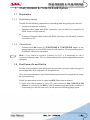
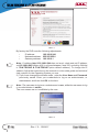
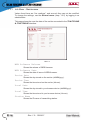
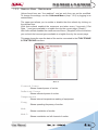
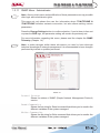
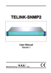
/TLW-TEX2HE &
/TLW-TEX3HE
USER MANUAL
Additional Manual for
TEX-LCD series
and TEX-LIGHT series
Manufactured by R.V.R ELETTRONICA S.p.A. Italy
File Name:
TLW_ING_1.0.indb
Version:
1.0
Date:
15/04/2011
Revision History
Date
Version
15/04/2011 1.0
Reason
First edition
Editor
J. H. Berti
/TLW-TEX2HE & /TLW-TEX3HE - User Manual
Version 1.0
© Copyright 2011
R.V.R. Elettronica SpA
Via del Fonditore 2/2c - 40138 - Bologna (Italia)
Phone:
+39 051 6010506
Fax:
+39 051 6011104
Email:
[email protected]
Web:
www.rvr.it
All rights reserved
Printed and bound in Italy. No part of this manual may be reproduced,
memorized or transmitted in any form or by any means, electronic
or mechanic, including photocopying, recording or by any information storage and retrieval system, without written permission of the
copyright owner.
ELETTRONICA
/TLW-TEX2HE & /TLW-TEX3HE
Table of Contents
1.
1.1
1.2
1.3
1.4
/TLW-TEX2HE & /TLW-TEX3HE Option
Preparation
First Power-On and Set-Up
Web User Interface (WUI)
SNMP Telemetry
User Manual
1
1
1
1
19
ELETTRONICA
This page was intentionally left blank
ii
Rev. 1.0 - 15/04/11
User Manual
/TLW-TEX2HE & /TLW-TEX3HE
ELETTRONICA
1. /TLW-TEX2HE & /TLW-TEX3HE Option
1.1
1.1.1
Preparation
Preliminary checks
Provide for the following (applicable to operating tests and putting into service):
√ Connection cable kit including:
•
Ethernet cable (cable with RJ45 connector, not included) for connection to
ADSL router or LAN network;
or
•
1.1.2
Crossover Ethernet cable (cable with RJ45 connector, not included) for direct
connection to PC.
Connections
•
Connect the LAN output of /TLW-TEX2HE & /TLW-TEX3HE option to the
appropriate input of your ADSL router or LAN network. If the connecting device
is different, identify an equivalent.
Note : If you intend to connect it directly to a PC, it is necessary to use a
crossover ethernet cable. This is a basic prerequisite to ensure equipment correct
operation.
1.2
First Power-On and Set-Up
Perform this procedure upon first power-up and each time you make changes to
the configuration this component is integrated into.
Once all connections previously described are performed, the equipment is ready
for commissioning.
Follow the procedure below to open the WUI (Web User Interface):
1) Open your web browser on your PC, and connect to http://192.168.0.244
address to connect to the WUI (if LAN IP address was previously modified, it
is necessary to use the new one). At this point the following page opens:
User Manual
ELETTRONICA
Menu 1
By factory the RVR uses the following adjustments:
•
•
•
IP address:
192.168.0.244
Netmask address: 255.255.255.0
Gateway address: 192.168.0.1
Note : If address http://192.168.0.244 does not work, check and set IP address
as 192.168.0.XXX (where XXX is a figure between 0 and 255, excluding 244 that
is /TLW-TEX2HE & /TLW-TEX3HE option default address). To change the IP
address, follow the instructions in the manual or in the online guide and technical
help, specific for the Operating System you use.
2) If you have changed the access mode , enter the User Name and Password
previously saved. Enter your credentials to log on as administrator, or
maintenance, and then click OK on the item.
Note : The username to log in as a maintenance is user, while the user name to log
in as administrator is admin.
The user names are not modifiable by the user.
Menu 2
2 / 24
Rev. 1.0 - 15/04/11
User Manual
ELETTRONICA
/TLW-TEX2HE & /TLW-TEX3HE
Note : Log in as maintenance enables only readings inside the WUI.
3) Now the interface is ready to remotely read data and modify the various settings
of the equipment.
1.3
Web User Interface (WUI)
The WUI (Web User Interface) allows you to adjust, modify or display the
configuration variables and the operation data.
Once logged in, you will see the Main Menu that shows the possible selections.
Menu 3
The image shows the Main Menu logging in normally. If you log in without
administrative privileges, and then only as a maintainer, in the WUI will be available
only the readings.
The page that appears is divided into three frames:
1) Title: it has the RVR logo and an identification of the current page
displayed. It is located on the top of the page.
If you still want return to the Main Menu, simply click on the RVR logo sited in
all the submenus on top left.
2) Navigation menu: it allows you to select the page to display.
To enter into a submenu, select the name and then click on the item to enter.
3) Body: area where the page displays information about the selected menu.
User Manual
ELETTRONICA
1.3.1
Info Menu - Maintenance
Values found here are “live readings”, and as such they can not be modified.
To change the settings, use the General menu (chap. 1.3.5) by logging in as
administrator.
This page shows the user the data of the exciter connected to the /TLW-TEX2HE
& /TLW-TEX3HE interface:
Menu 4
WEB Software Release
Shows the release of WEB firmware.
WEB Software Date
Shows the date of issue of WEB firmware.
Device Date
Shows the day stored on the exciter (dd/MM/yyyy).
Device Time
Shows the time stored on the exciter (hh:mm).
Local Date
Shows the day stored in your browser device (dd/MM/yyyy).
Local Time
Shows the time stored in your browser device (hh:mm).
Station Name
Shows the ID name of transmitting station.
4 / 24
Rev. 1.0 - 15/04/11
User Manual
/TLW-TEX2HE & /TLW-TEX3HE
ELETTRONICA
1.3.2
Measure Menu - Maintenance
Values found here are “live readings”, and as such they can not be modified.
To change the settings, use the Command Menu (chap. 1.3.6) by logging in as
administrator.
The upper part allows you to enable or disable the Auto-refresh by clicking on
the relevant box.
With Auto-refresh enabled the measures are taken every 3 seconds (“Get
Data ..”) and gave available in a legible form by the current page (“Ready”).
With Auto-refresh disabled the measures are frozen (“Stopped”) at the time when
you uncheck the box and gave available in a legible form by the current page.
This page shows the user the data of the exciter connected to the /TLW-TEX2HE
& /TLW-TEX3HE interface:
Menu 5
Forward Power
Shows forward power of exciter.
Reflected Power
Shows reflected power of exciter.
Temperature
Shows internal temperature reading of equipment.
Freq.
Mod.
Mod.L
User Manual
Shows operating frequency of exciter.
Shows modulation of exciter.
Shows modulation on left channel of exciter.
ELETTRONICA
Mod. R
Shows modulation on right channel of exciter.
PLL LOCK
Shows the lock status at frequency set by PLL.
Audio Alarm
Shows the status of an impasse due to excessive SWR.
Foldback
Shows the triggered status of the foldback function (automatic reduction
of output power).
Ext R.F. Mute
Shows the status of power inhibition by an interlock signal.
Ack ON
Shows the power on status of the exciter.
Ack OFF
Shows the power off status of the exciter.
Ack Nom
Shows the delivery status of fixed nominal power.
Ack Low
Shows the delivery status of fixed reduced power.
FAULT Mains
Shows the status of alarm conditions that affect the proper
functioning.
CMD ON
Not Used.
CMD OFF
Not Used.
CMD Nom
Not Used.
CMD Low
Not Used.
NOM Power
Shows the efficiency about the adjustment of nominal power.
LOW Power
Shows the efficiency about the adjustment of reduced power.
6 / 24
Rev. 1.0 - 15/04/11
User Manual
/TLW-TEX2HE & /TLW-TEX3HE
ELETTRONICA
1.3.3
Alarm List Menu - Maintenance
Values found here are “live readings”, and as such they can not be modified. To
change the settings, use the Alarm Delete Menu (chap. 1.3.7) by logging in as
administrator.
This page shows the user the data of the exciter connected to the /TLW-TEX2HE
& /TLW-TEX3HE interface:
Menu 7
Type
Shows the alarm code.
Name
Shows the description for the error that led to event recording.
Time
Shows event recording time (hh:mm).
Date
Shows the day event was recorded (dd/MM/yyyy).
Value
Shows progressive number for event recording.
User Manual
ELETTRONICA
1.3.4
Password Menu - Maintenance
This page allows the configuration of login as a maintenance of /TLW-TEX2HE &
/TLW-TEX3HE interface via WUI.
Please note that the User Name (user) can not be changed.
Menu 8
Password
Shows and set the password for maintenance user (enables
read-only parameter).
The Erase button allows you to delete the password set.
8 / 24
Rev. 1.0 - 15/04/11
User Manual
/TLW-TEX2HE & /TLW-TEX3HE
ELETTRONICA
1.3.5
General Menu - Administrator
Note : Access to this menu and modification of these parameters are only possible
after login with administrator rights.
This page not only shows the user the information about the exciter connected
to /TLW-TEX2HE & /TLW-TEX3HE interface, but also allows setting various
parameters.
Below will be described only items that allow the modification of the parameter,
with respect to the Information menu (chap. 1.3.1). Press the buttons to confirm
your choice, pushing the logo RVR, instead, or wait at the time-out, the parameter
will be set to the previous one.
Menu 9
Device Date/Time
Allows you to align the time and date stored in the exciter with that of
browser device, by pressing the Synchronize Clock button.
New Station Name
Setting of the station name. Write the name in the box that you want to
assign, then press the Change Name button to apply the choice.
Main Mib
By pressing the MIB (Management Information Base) highlighted you
can download onto your PC, or browser device, the general database
for the management of devices in communications networks.
Specific Mib
By pressing the MIB (Management Information Base) highlighted you
can download onto your PC, or browser device, the specific database
for the management of devices in communications networks.
User Manual
ELETTRONICA
1.3.6
Command Menu - Amministrazione
Note : Access to this menu and modification of these parameters are only possible
after login with administrator rights.
This page not only shows the user the information about the exciter connected
to /TLW-TEX2HE & /TLW-TEX3HE interface, but also allows setting various
parameters.
Below will be described only items that allow the modification of the parameter,
with respect to the Measure menu (chap. 1.3.2). Press the buttons to confirm your
choice, pushing the logo RVR, instead, or wait at the time-out, the parameter will
be set to the previous one.
Menu 10
Freq.
CMD ON
Remote adjustment of exciter frequency. This value, in MHz, can be
modified according to one’s own band in 0.1 MHz steps. Press Set to
confirm the value inserted.
Press Set to change the logical state of the data.
CMD OFF
Press Set to change the logical state of the data.
CMD Nom
Press Set to change the logical state of the data.
10 / 24
Rev. 1.0 - 15/04/11
User Manual
/TLW-TEX2HE & /TLW-TEX3HE
ELETTRONICA
CMD Low
Press Set to change the logical state of the data.
NOM Power
Remote adjustment regarding the nominal power of exciter. This value,
in %, can be modified in the range 0 to 100, in steps of 1%. Press Set
to confirm the value inserted.
LOW Power
Remote adjustment regarding the reduced power of exciter. This value,
in %, can be modified in the range 0 to 100, in steps of 1%. Press Set
to confirm the value inserted.
1.3.7
Alarm Delete Menu - Amministrazione
Note : Access to this menu and modification of these parameters are only possible
after login with administrator rights.
Within this menu you can view the most recent alarms stored by the system, a new
event will cause an automatic cancellation of the oldest. Using the Reset item in
the bottom right side of menu, you can delete the list of all pending alarms.
Menu 11
User Manual
ELETTRONICA
1.3.8
Password Menu - Administrator
Note : Access to this menu and modification of these parameters are only possible
after login with administrator rights.
This page allows the configuration of login as an administrator and maintenance
of /TLW-TEX2HE & /TLW-TEX3HE interface via WUI.
Please note that the User Name (admin for administrator, or user for maintenance)
can not be changed.
Menu 12
user Password
Shows and set the password for user functions (parameter
read-only enabling).
The Erase button allows you to delete the password set for
maintenance.
admin Password
Shows and set the password for administrator functions
(parameter reading and change enabling).
The Erase All button allows you to delete the password set both for the
administrator and for the maintenance.
12 / 24
Rev. 1.0 - 15/04/11
User Manual
/TLW-TEX2HE & /TLW-TEX3HE
ELETTRONICA
1.3.9
Network Menu - Administrator
Note : Access to this menu and modification of these parameters are only possible
after login with administrator rights.
This page not only shows the user the information about /TLW-TEX2HE &
/TLW-TEX3HE interface network connection, but also allows setting various
parameters.
Press the Change Settings button to confirm selection; if you let timer to time out
or press the RVR logo, the parameter setting will remain as previously set.
Note: to make changes within these sub-menus you need to have thorough
technical knowledge of network management. It is recommended to have changes
performed by trained or qualified personnel.
Menu 13
IP address
Shows the number that unequivocally identifies, within a single network,
the devices connected to an IT network that uses the IP standard
(Internet Protocol).
Subnet Mask
Shows the subnet mask, necessary for the computer that must
communicate with another IP address to know if it should route packages
toward the gateway of its local network or use the address of the receiver
local network.
User Manual
ELETTRONICA
Gateway
Shows gateway address. In simpler networks, there is only one gateway
that forwards to the internet network all the outbound traffic. In more
complicated networks where many subnets are available, each of them
refers to a gateway that will route data traffic towards the other subnets
or forward it to other gateways.
DNS1 server
Shows the first DNS server address (Domain Name System); in case the
server should change the server hosting a service, or it is necessary to
change its IP address, it is enough to change the DNS record, without
changing client settings.
DNS2 server
Shows the second DNS server address (Domain Name System); in
case the server should change the server hosting a service, or it is
necessary to change its IP address, it is enough to change the DNS
record, without changing client settings.
MAC Address
Shows the MAC (Media Access Control) address; this address is
uniquely assigned to the ethernet network card present on exciter. It
can be useful if you want to add in your router, or firewall, a list of MAC
addresses of network cards authorized to connect to the network.
New IP address
Set the new IP (Internet Protocol) number.
New Subnet Mask
Set the new subnet mask
New Gateway
Set the new gateway address.
DNS1 server
Set the new first DNS server address (Domain Name System).
DNS2 server
Set the new second DNS server address (Domain Name System).
14 / 24
Rev. 1.0 - 15/04/11
User Manual
/TLW-TEX2HE & /TLW-TEX3HE
ELETTRONICA
1.3.10
Mail Menu (SMTP) - Administrator
Note : Access to this menu and modification of these parameters are only possible
after login with administrator rights.
This page not only shows the user the information about /TLW-TEX2HE &
/TLW-TEX3HE interface network connection, but also allows setting various
parameters.
Press the Change Settings button to confirm selection; if you let timer to time out
or press the RVR logo, the parameter setting will remain as previously set.
Note: to make changes within these sub-menus you need to have thorough
technical knowledge of network management. It is recommended to have changes
performed by trained or qualified personnel.
Menu 14
Sender Address
Shows the transmission address used for sending messages.
Destination 1
Shows the first address to which alarm warning mail messages shall
be sent.
Destination 2
Shows the second address to which alarm warning mail messages
shall be sent.
User Manual
ELETTRONICA
Destination 3
Shows the third address to which alarm warning mail messages shall
be sent.
Destination 4
Shows the fourth address to which alarm warning mail messages shall
be sent.
Subject
Shows the description of the “subject” field of the mail.
Server Port
Shows the port used by TCP transmission protocol.
New Sender Address
Set the new transmission address used for sending messages.
New Destination 1
Set the new first address to which alarm warning mail messages shall
be sent.
New Destination 2
Set the new second address to which alarm warning mail messages
shall be sent
New Destination 3
Set the new third address to which alarm warning mail messages shall
be sent
New Destination 4
Set the new fourth address to which alarm warning mail messages
shall be sent
New Subject
Set the new description of the “subject” field of the mail.
New Server Port
Set the new port used by TCP transmission protocol.
16 / 24
Rev. 1.0 - 15/04/11
User Manual
/TLW-TEX2HE & /TLW-TEX3HE
ELETTRONICA
1.3.11
SNMP Menu - Administrator
Note : Access to this menu and modification of these parameters are only possible
after login with administrator rights.
This page not only shows the user the information about /TLW-TEX2HE &
/TLW-TEX3HE interface network connection, but also allows setting various
parameters.
Press the Change Settings button to confirm selection; if you let timer to time out
or press the RVR logo, the parameter setting will remain as previously set.
For more information regarding this menu, please read the chapter the SNMP
Telemetry (Chapter 1.4).
Note: to make changes within these sub-menus you need to have thorough
technical knowledge of network management. It is recommended to have changes
performed by trained or qualified personnel.
Menu 15
Actual Status
Shows the status of SNMP (Simple Network Management Protocol)
service.
Read Community
Shows the set string for Read command that allows you to monitor the
different variables of the system managed.
Write Community
Shows the set string for Write command that allows you to monitor the
different variables of the system managed.
User Manual
ELETTRONICA
Primary TRAP IP
Shows the first identification number of the IP address set to send the
TRAP signaling that configures the agent to send a special message
to the occurrence of certain events.
Primary TRAP Port
Shows the first port number set by the TCP transmission protocol for the
TRAP signaling that configures the agent to send a special message to
the occurrence of certain events. The port can not be changed.
Secondary TRAP IP
Shows the second identification number of the IP address set to send
the TRAP signaling that configures the agent to send a special message
to the occurrence of certain events.
Secondary TRAP Port
Shows the second port number set by the TCP transmission protocol for
the TRAP signaling that configures the agent to send a special message
to the occurrence of certain events. The port can not be changed. .
New Status
Set the status of SNMP (Simple Network Management Protocol)
service.
New Read Community
Set the string for Read command.
New Write Community
Set the string for Write command.
New Primary TRAP IP
Set the first identification number of the IP address set to send the
TRAP signaling.
New Secondary TRAP IP
Set the second identification number of the IP address set to send the
TRAP signaling.
18 / 24
Rev. 1.0 - 15/04/11
User Manual
ELETTRONICA
1.4
/TLW-TEX2HE & /TLW-TEX3HE
SNMP Telemetry
SNMP (Simple Network Management Protocol) is a worlwide protocol that allows
the management and supervision of the equipment connected to the network.
Measurements and commands are described by a MIB (Management Information
Base), which is a list of OID (Object Identifi er). Each OID is a variable that can
be written (SET) or read (GET) through a NMS (Network Management System)
compatible with SNMP.
The MIB is a text fi le written in ASN.1 and it is imported from the NMS in order to
know what OID can be expected by the AGENT and how to interpret the information
received.
Note: The user can not freely distribute the MIB, unless written authorization issued
by the manufacturer. The MIB is property of the manufacturer.
Note: The MIB files are downloaded in the web section or requested separately
to the manufacturer.
The SNMP version used in this application is the v2, then is also compatible with
v1 NMS systems, except in the TRAP receiving section.
Here is the list of MIB necessary for equipments of RVR equipments:
Figure 1
Note: Use a MIB BROWSER (not included) to use the MIB of RVR equipments.
User Manual
ELETTRONICA
1.4.1
Reading of the Measures (Read)
Each transmitter has a range of measures that can be read. Please refer to MIB
for a detailed description of each measurement.
Note: In the following examples is used a proprietary MIB browser, but any MIB
Browser can be used.
In the following example, the measure of Forward Power is indicated as
READONLY:
Figure 2
Into the MIB are specified the range and description of each variable, in this case
the forward power and possible alarms, which are reported into the description
box of browser. If the READ ONLY and MANDATORY conditions are present, they
mean that the value is been obtained.
20 / 24
Rev. 1.0 - 15/04/11
User Manual
ELETTRONICA
1.4.2
/TLW-TEX2HE & /TLW-TEX3HE
Settings of the Measures (Write)
Similarly to readings and settings of the measurements, the commands have a
set of OID that are only in writing mode.
Tipically the value of command are read as “1”; the user must send a “2” as value
to send a command. No other values are accepted as a command.
Usually the commands are one-shot toggle. In other words, if the transmitter is turn
“ON” (value “2” on set-transmitter-on), the next command is a turn “OFF” (value
“2” on set-transmitter-off).
In the following example, the command of Set-Transmitter-On is indicated as
READWRITE:
Figure 3
Into the MIB are specified the range and description of each variable, in this case is
shown the description of command brought in information box of your browser.
User Manual
ELETTRONICA
1.4.3
Settings of the TRAP
For each TRAP can be set:
•
Enable/disable the send of TRAP.
•
The maximum value (MAX) is the fi xed point beyond which is sent a TRAP.
•
The minimum value (MIN) is the fi xed point below which is sent a TRAP.
•
The hysteresis value is a nominal value that the system adds (or subtracts) to
real value in order to exit from alarm condition.
In other words, it is helpful to avoid situations of continuous alarm, if readout
is very close to the set point alarm.
Figure 4
22 / 24
Rev. 1.0 - 15/04/11
User Manual
/TLW-TEX2HE & /TLW-TEX3HE
ELETTRONICA
1.4.4
Sending of the TRAP
The system properly configured is capable to sending TRAP up to two different
addresses. Different addresses can be set using the OID presents in the main
MIB.
The generation and sending happens if the parameter exceeds the maximum and
minimum set up and as you can see the hysteresis is a protected area in which
the alarm is not sent.
Figure 5
Note: the hysteresis value shall be properly adjusted to not overlap to the distance
between the minimum (MIN) and the maximum value (MAX).
Inside the generated TRAP are indicated:
•
Progressive number of the TRAP.
•
Date of generation.
•
Time of generation.
•
The OID and its instantaneous value.
The TRAP that you can set are the ones shown in the picture below:
Figure 6
User Manual
ELETTRONICA
This page was intentionally left blank
24 / 24
Rev. 1.0 - 15/04/11
User Manual
______________________________________________________________________________
______________________________________________________________________________
______________________________________________________________________________
______________________________________________________________________________
______________________________________________________________________________
______________________________________________________________________________
______________________________________________________________________________
______________________________________________________________________________
______________________________________________________________________________
______________________________________________________________________________
______________________________________________________________________________
______________________________________________________________________________
______________________________________________________________________________
______________________________________________________________________________
______________________________________________________________________________
______________________________________________________________________________
______________________________________________________________________________
______________________________________________________________________________
______________________________________________________________________________
______________________________________________________________________________
______________________________________________________________________________
______________________________________________________________________________
______________________________________________________________________________
______________________________________________________________________________
______________________________________________________________________________
______________________________________________________________________________
______________________________________________________________________________
______________________________________________________________________________
______________________________________________________________________________
______________________________________________________________________________
______________________________________________________________________________
______________________________________________________________________________
______________________________________________________________________________
______________________________________________________________________________
______________________________________________________________________________
______________________________________________________________________________
______________________________________________________________________________
______________________________________________________________________________
______________________________________________________________________________
______________________________________________________________________________
______________________________________________________________________________
______________________________________________________________________________
______________________________________________________________________________
______________________________________________________________________________
______________________________________________________________________________
______________________________________________________________________________
______________________________________________________________________________
______________________________________________________________________________
______________________________________________________________________________
______________________________________________________________________________
______________________________________________________________________________
______________________________________________________________________________
______________________________________________________________________________
______________________________________________________________________________
______________________________________________________________________________
______________________________________________________________________________
______________________________________________________________________________
______________________________________________________________________________
______________________________________________________________________________
______________________________________________________________________________
______________________________________________________________________________
______________________________________________________________________________
______________________________________________________________________________
______________________________________________________________________________
______________________________________________________________________________
______________________________________________________________________________
______________________________________________________________________________
______________________________________________________________________________
______________________________________________________________________________
______________________________________________________________________________
______________________________________________________________________________
______________________________________________________________________________
______________________________________________________________________________
______________________________________________________________________________
______________________________________________________________________________
R.V.R Elettronica S.p.A.
Via del Fonditore, 2 / 2c
Zona Industriale Roveri · 40138 Bologna · Italy
Phone: +39 051 6010506 · Fax: +39 051 6011104
e-mail: [email protected] ·web: http://www-rvr-it
ISO 9001:2000 certified since 2000
The RVR Logo, and others referenced RVR products and services are trademarks of RVR Elettronica S.p.A. in Italy, other countries or both. RVR ® 1998 all rights reserved.
All other trademarks, trade names or logos used are property of their respective owners.