1
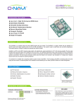
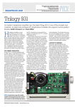
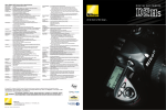
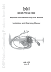
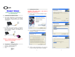
TM
+ High Performance MEMS Inertial Sensors
+ Compensated bias and scale factor
+ RS-232 Serial Interface
+ On-Board Temperature Monitor
+ Low Cost
+ Ultra Compact Package
+ Low Power Consumption (Single 5V Supply)
The Falcon/GX is a complete three axis silicon MEMS inertial measurement module with serial output. The Falcon/GX integrates a high
performance 32bit RISC CPU with three MEMS angular rate gyros and three MEMS accelerometers in a triaxial orthogonal configuration.
Featuring fully compensated bias and scale factor, these rugged inertial sensor modules are rated for 500g operating and 1000g non-operating
shock survival. The module requires a single 5V supply and consumes only 445mW.
Angular rate outputs are available in two ranges of ±150°/s or ±300°/s, with optional gain, output sensitivities can be configured to ±15°/s full
scale. Acceleration outputs are available in two ranges ±2g or ±10g, with optional gain, output sensitivities to ±0.5g full scale are available.
Automatic self-test verifies proper sensor operation.
Digital outputs are 10bit (1024 count) with user selectable sampling rates and digital half-band filtering for angular rate and acceleration in addition
to fifth-order analog low-pass filters. Temperature output is also provided. Outputs are terminated on a detent-locking header for reliable contact in
dynamic environments. The wire-to-board connection allows mounting the module in any orientation. Preassembled cable sets are available for
easy system integration.
An evaluation kit is available with everything needed to power and test a Falcon/GX on a desktop or in your application. The evaluation kit includes
a Falcon/GX, connecting cables, AC power supply and a user manual. An optional aluminum enclosure is available for installations in harsh
environments.
+ Platform Stabilization
+ Attitude Reference Systems
+ Motion Control Systems
+ Seismic Event Sensing
+ Inertial Guidance & Navigation
+ Motion Instrumentation
+ Vehicle Stabilization & Control
+ Virtual Reality Input Sensing
+ Antenna Tracking
+ Vehicle Failsafe Systems
FALCON/GX
CUSTOM CONFIGURATIONS
ONI-23505±150°/s
±300°/s
2g
10g
40Hz
80Hz
Standard stock configuration is ±150°/s (40Hz) angular rate & ±2g (60Hz) acceleration.
Custom bandwidth and mixed sensitivities/bandwidths are available.
Custom I/O Header (Removed or Reversed)
Custom Bandwidth 40-100Hz
Custom Rate Gain ±300 to ±15°/s
Standard cable / connector sets
Aluminum Enclosures
DISCLAIMER
Data contained herein is believed to be reliable and
accurate. O-Navi LLC assumes no liability for the use of
any information contained herein, nor for any
infringements of patents or other rights of third parties that
may result from its use. No license is granted for any
patent rights of O-Navi LLC.
© 2003 O-NAVI, LLC, All rights reserved
www.o-navi.com
ONI-23505 Rev A 6/30/2003
PAGE 1 OF 2
±2
800
2.0
1000
±0.5
0.2
200
2.5
2.0
1
±2
50
10
1.0
10
<20
±300
1200
1000
3.0
4.0
Full Scale (F.S.) Range
@25°C
4.75V<VCC<5.25V
4.75V<VCC<5.25V
Best Fit Straight Line
@25°C
g
mV/g
%
% F.S.
µg Hz
V
mg/°C
°
%
Hz
kHz
%/V
%
mS
Full Scale (F.S.) Range
@25°C
Delta from 25°C
Best Fit Straight Line
@25°C
Bias = 1/2VCC ±0.5V
DIMENSIONS
0.150
°/s
mV/°/s
mV/°/s
%/V
% F.S.
°/s/ Hz
V
mV
°/s/V
Hz
KHz
°/s/g
mS
2.350
1.940
4.75V<VCC<5.25V
-3db
0.120D
(4 PLCS)
Any Axis
To within ±0.5°/s of final
0.110
0.110
1.250
1
40
14
0.2
35
13.75
13.75
CONDITIONS / REMARKS
TOP VIEW
1.650
KEEP CLEAR
0.450
0.7
0.10
0.05
2.5
UNITS
KEEP CLEAR
11.25
11.25
±150
12.5
MAX
1.030
TYP
0.165
ACCELERATION
Dynamic Range
Sensitivity
Sensitivty Drift over Temp
Non-Linearity
Noise Density
Bias
Offset Drift
Sensor Die Align Error
Cross Axis Sensitivity
Bandwidth
Resonant Freq (Sensor)
Supply Voltage Sensitivity
Self-Test Deviation
Start-up Time
MIN
0.180
PARAMETER
ANGULAR RATE
Dynamic Range
Sensitivity
Sensitivity (Over Temp)
Voltage Sensitivity (Scale)
Non-Linearity
Noise Density
Bias
Bias Temp Drift
Voltage Sensitivity (Bias)
Bandwidth
Self Resonant Freq
Linear Acceleration Effect
Start-up Time
KEEP CLEAR
-3db
0.062
Z PROFILE
BW: 50Hz
TEMP SENSOR
Temperature Output
Temperature Scale
Temp. Output Drive
ELECTRICAL
Supply Voltage
Supply Current
Power
PHYSICAL
Temp Range (OP)
Temp Range (NOP)
Shock (OP)
Shock (NOP)
Humidity
Mass
Dimensions:
Mounting Hole:
Interface Connector:
Mating Connector:
2.5
8.4
4.75
5.00
89
445
-40
-65
0
11.5
50
5.25
+85
+125
500
1000
90
V
mV/°C
µA
V
mA
mW
°C
°C
g
g
% R.H.
gram
@25°C
AXIAL SENSITIVITY
+g = +v
Vcc=5V
Vcc=5V
+av = +v
Y
Absol Max: -55 to +125°C
Any Axis 0.5mS
Any Axis 0.5mS
Non-Condensing
Z
X
63.50 X 31.75 X 15.62MM
Diameter 3.175mm (M3 or SAE 4-40)
JST - B6B-ZR
JST - ZHR-6
CONNECTOR PINS
PIN OUT
OPTIONS
I/O Cable (Flying Leads)
I/O Cable (Power Connector)
AC Power Supply (US Plug)
Stand-Off Kit (1/2" X 4-40) [w/Screws]
1 - +5V
2 - SDI
3 - SDO
4 - N/C
5 - GND
6 - GND
305-0606A
305-0635A
310-0502A
810-7440
PIN 1
SPECIFICATION SUBJECT TO CHANGE WITHOUT NOTICE
TM
PATENT PENDING
O-Navi LLC
PO Box 27213, San Diego, CA 92198
TEL 877-722-6688
FAX 760-874-2850
www.o-navi.com
© 2004 O-NAVI, LLC, All rights reserved - ONI-23504 Rev B 6/30/2004 - PAGE 2 of 2