1
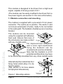
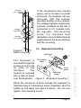
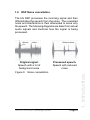
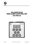
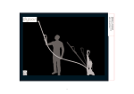
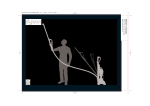
Important Information Copyright This publication, including all photographs and illustrations is protected under international copyright laws, with all rights reserved. Neither this manual, nor any of the material within, may be copied or reproduced without the written consent of bhi Ltd. Disclaimer The information in this document is subject to change without notice. bhi Ltd. makes no representations or warranties with respect to the contents hereof and specifically disclaims any implied warranties of merchantability or fitness for any particular purpose. Furthermore, bhi Ltd. reserves the right to revise this publication and to make changes from time to time in the content hereof without obligation of bhi Ltd. to notify any person of such revision or changes. Page 2 NEDSP1062-KBD Operating Manual Contents 1. Introduction 1.1 1.2 1.3 1.4 1.5 1.6 2. 2.5 3.3 10 11 11 12 12 12 12 Installation overview Module setup 3.2.1 Overview 3.2.2 Suggested set up procedure 3.2.3 Changes to output load 3.2.4 Other signal considerations Driving the module from a low level signal 16 17 17 17 18 18 19 Functions 4.1 4.2 4.3 4.4 5. Block diagram Module layout Pin functions Controls 2.4.1 PCB controls 2.4.2 Keyboard Electrical characteristics Installation 3.1 3.2 4. 5 5 6 7 8 9 Module description 2.1 2.2 2.3 2.4 3. NEDSP1062-KBD features Limitations Module connection and mounting Keyboard mounting Sounder mounting DSP noise cancellation Keyboard 4.1.1 Power button 4.1.2 DSP level button Set up Demonstration modes Noise cancellation levels 20 20 20 21 23 24 Application notes 5.1 5.2 5.3 Yaesu SP8 Kenwood SP31 bhi label NEDSP1062-KBD Operating Manual 25 28 31 Page 3 6. Physical dimensions 6.1 6.2 7. Physical dimensions Keyboard hole drilling detail Troubleshooting Troubleshooting 8. 32 35 37 Other bhi products Other bhi products Page 4 38 NEDSP1062-KBD Operating Manual 1. Introduction. The NEDSP1061-KBD is a modular solution for noise reduction. It incorporates Digital Signal Processing (DSP) technology to provide up to 35dB of noise cancellation and 65dB of tone reduction. The module features an on board power amplifier to allow it to be easily incorporated in to existing equipment by installing the module in line with the loudspeaker. All functions of the module are controlled by an easy to use keyboard. Fully adaptive noise cancellation up to 35dB Input and output level controls Input level over load indication Virtually no distortion to speech signal Easy to install Up to 8 levels of noise reduction (selectable) Frequency response 50Hz - 4.3KHz 3 Watts output (4W) Single button operation with LED and audible indication 12 - 18V supply range 27dB on board gain Power on/off - bypass pushbutton Small size 37 x 50mm (DSP pcb) Audio bypassed when power disconnected Supplied with fixing and wiring kit and all labels 1.2 Limitations. This module is designed to pass speech. Other signals such as data, music and morse (CW) will to some degree pass through depending on the current filter level, but the integrity of these signals cannot be guaranteed. NEDSP1062-KBD Operating Manual Page 5 1. Introduction. 1.1 NEDSP1062-KBD module features: This module is designed to be driven from a high level signal, capable of driving a load of 22W. (The module can be easily modified to be driven from a low power signal, see section 3.3 for more information). 1.3 Module connection and mounting 1. Introduction. The module is supplied with a pre-wired 2.1mm power connector. The centre pin is positive. The audio in and out are pre-wired pairs of wires, ready to be connected in the audio path. The heatsink doubles up as a mounting bracket. The module can be mounted using the supplied self adhesive foam pad. Ensure that none of the circuit pins can make contact Self adhesive pad with any metallic parts. For improved heat dissipation and a more rigid mechanical fixing the heatsink can be reversed and used as a bracket. Using the heatsink Note that the heatsink is at 0V as bracket potential and therefore may have to be electrically insulated from any other metallic parts. Alternatively the module has four fixing holes which allow it to be fixed to pillars. (See section 6 for hole details and physical dimensions). Figure 1. Mounting options Page 6 Mounting using PCB pillars NEDSP1062-KBD Operating Manual Insulator (not supplied) Voltage Regulator Insulator (not supplied) Figure 2. Direct mounting. If the installation has limited space, and is housed in a metal enclosure, the heatsink can be removed, and the module mounted directly on the chassis. The voltage regulator needs to be correctly insulated as the tab is connected to 0V. Insulate both the regulator and mounting screw. For improved heat dissipation use a suitable thermal paste between the power devices and the mounting. 1.4 Keyboard mounting. The keyboard is Front panel label mounted through the enclosure to provide Front an easy to use panel interface. The Retaining module is supplied screw with a label to place over the keyboard. Figure 3. Keyboard mounting 1. When the enclosure is thick enough the keyboard is retained using a countersunk screw (supplied), which is hidden by the label, see figure 3 above. Do not over tighten the mounting screw. NEDSP1062-KBD Operating Manual Page 7 1. Introduction. keyboard Nut & If the enclosure is too keyboard washer thin to incorporate a Front panel countersunk screw label (such as fitting into sheet metal) then it can be retained by a instrument head Front screw. panel The label needs to be Cut hole cut out to allow the Retaining for screw screw screw to pass through from the outside. This Figure 4. can be easily achieved Keyboard mounting 2. by applying the label to the panel, then carefully cutting around the screw hole, with a sharp knife. Again do not over tighten the screw. 1. Introduction. 1.5 Sounder mounting. Sounder Backing paper Cut a small piece of the self adhesive foam Self adhesive foam (supplied) to mount the sounder. Do not cover the small hole in the face of the Keep this hole clear sounder. For best results mount Backing the sounder where it paper can radiate sound to the outside the case, Case for example on an air vent. Figure 5. Sounder mounting Page 8 NEDSP1062-KBD Operating Manual 1.6 DSP Noise cancellation. The bhi DSP processes the incoming signal and then differentiates the speech from the noise. The unwanted noise and interference is then attenuated to leave only the speech. The following diagrams are taken from actual audio signals and illustrate how the signal is being processed. Speech Noise Original signal. Speech with a lot of background noise Reduced noise Processed speech. Speech with reduced noise NEDSP1062-KBD Operating Manual 1. Introduction. Figure 6. Noise cancellation. Page 9 2. Module description. 2.1 Block diagram. Xtal PCB Connections Output level set Power Amp N/C 6 Out 10 Agnd 11 Agnd 12 Relay 1 Digital to analogue conversion NC DSP core BCD DSP level select 8 NO Clock generator Analogue to Digital conversion N/C In Input level set overload detect 9 Input Load resistor 2. Module description. 1 Keyboard interface microcontroller 4 3 8 Internal pull up resistors Relay 1 NO DSP Polarity protection 0V 3.3V regulator 12V regulator Latch 3.3V 5 5V 13 ON 14 0V 7 NC 5V Regulator 3V3 Vin 12V Relay Drive Power supply section J3 PCB Figure 7. NEDSP1062-KBD block diagram Page 10 NEDSP1062-KBD Operating Manual 2.2 Module Layout. The following diagram shows the layout of the NEDSP1062-KBD module. Note: Wiring obmitted for clarity Input level set (P2) Audio bypass relay Input overload indicator LED Output level set (P1) Sounder volume (P3) Figure 8. NEDSP1062-KBD connections and controls 2.3 Pin functions. The following table gives a description of the pin functions. Pin No. Name 4 N/C Do not connect Description Not used Notes 5 Vi n Supply voltage 12 - 18VDC power in 6 N/C Do not connect Not used 7 0V 0V connection 0V power connections 9 In Audio input Audio signal in to be processed 10 Out Audio output Procesed audio signal out 11 Agnd 0V for input audio signal Analogue ground for audio in 12 Agnd 0V for output audio signal Analogue ground for audio out Table 1. NEDSP1062 connection functions NEDSP1062-KBD Operating Manual Page 11 2. Module description. Mounting holes 2.4 Controls. 2.4.1 PCB. The level controls provide adjustment for the audio levels entering and leaving the module. The modules are factory set to the maximum level. Turning the potentiometers clock wise will decrease the levels. These potentiometers do not have end stops, so it is possible to set them in a position where the audio will be lost. 2. Module description. Audible indication of operation is provided by an piezo sounder. The volume of this sounder can be varied by potentiometer P3. The sounder volume is independent of the incoming audio volume. 2.4.2 Keyboard. The keyboard controls all of the module functions including power on/off. Mounting hole Tri colour LED Power button (power and Audio bypass) DSP level button Figure 9. NEDSP1062-KBD keyboard. Page 12 NEDSP1062-KBD Operating Manual 2.5 Electrical characteristics. ELECTRICAL CHARACTERISTICS i (Vs=16V, Tamb= 25 C unless otherwise stated) DC CHARACTERISTICS Symbol Parameter Test Conditions Min. Typ. Max. Units 12 16 18 V Vs Supply voltage Iqs Quiescent current V s = 12V V s = 16V V s = 18V 4.6 6.8 7.1 mA Iqon Quiescent current DSP on no load no signal V s = 12V V s = 16V V s = 18V 143 160 161 mA Symbol Parameter Test Conditions d = 10% f = 1KHz Min. Typ. Max. Units 12V 16V 18V Vs 2.06 3.17 W W Po Output power Vi Input sensitivty 4W W load Vi Input sensitivty 8W W load B Frequency response (-3dB) P o = 1W RL = 8W d Distortion f = 1KHz PO = 0.2 - 2.4W R L= 8W PO = 0.2 - 2.4W R L= 4W Ri Input resistance Gv Voltage gain f = 1KHz 27 dB Efficiency f = 1KHz PO = 3W R L = 4W PO = 2W R L = 8W 33 38 % RL = 8W RL = 4W 1.16 1.7 f = 1KHz PO = 0.5W PO = 1.0W PO = 2.0W 60 90 130 PO = 0.5W PO = 1.0W PO = 2.0W 81 117 180 mV f = 1KHz n 50 4300 0.8 0.8 21 22 mV Hz % W 23 ANALOGUE CHARACTERISTICS Symbol Td Parameter Test Conditions System delay Min Typ 26 Max. Units mS Table 2. Electrical characteristics 1 NEDSP1062-KBD Operating Manual Page 13 2. Module description. AC CHARACTERISTICS 3. Installation 3.1 Installation overview. The NEDSP1062-KBD module is inserted into the path of noisy audio. The input and output level controls allow the module to be fine tuned to suit most applications. Audio in + Audio Out (Loudspeaker) Power amp Break Circuit here Keyboard Audio in + Red 9 Power amp - IN OUT 10 Blue NEDSP1062 11 Black Agnd Agnd 12 Black Piezo sounder 3. Installation. Power Figure 13. Basic connection diagram The input to the module is loaded at 22W to provide a dummy load to the preceding circuit. This can be removed if required, such as using the module in applications where the audio source is provided by a low level, low power signal source. More information on this can be found in section 3.3 in this operating manual. If Vin is less than approx. 13.8V ensure the power supply is well decoupled otherwise the power supply rejection ratio will deteriorate. Best results are obtained in the range of 13.8V - 16Vdc. Page 16 NEDSP1062-KBD Operating Manual 3.2 Module setup. Both the input and output levels are adjustable on the module. This allows easy integration into the target system. 3.2.1 Overview. To obtain the best results from the noise reduction the module should be set up to give optimum performance. The input sensitivity control has a range of 0.70mW 3W to provide 2W (W)output. Under certain conditions, RF breakthrough can sometimes occur. To minimize this, the input level (P2) may need to be reduced or go to the FAQ page on the bhi website and download the FAQ on RF breakthrough. Under certain conditions the DSP can create a small amount of noise, normally when the unit has no signal applied. You should not be able to hear this noise when a signal is applied. Basic setup procedure. Connect input source and output device. Ensure the NEDSP1062- KBD is switched off. Set the audio source to a typical audio level. Switch on the NEDSP1062- KBD. Adjust the input control (P2) until the overload LED illuminates. Reduce the level by approx. 1/4 turn. Adjust the output level to the desired level. Hold down the DSP button and adjust the volume of the sounder to suit using P3. NEDSP1062-KBD Operating Manual Page 17 3. Installation. 3.2.2 Suggested set up procedure: 3.2.3 Change to output load. The audio input to the module is loaded at 22W. This load is effectively connected across the output load when the unit is switched off (bypassed). This will reduce the impedance presented to the audio source. 10 OUT 9 IN Audio Input R6 22W V Load Agnd 12 Agnd 11 NEDSP1062 3. Installation. For example: Figure 14. Input circuit 8W will reduce to 5.9W module powered down 4W will reduce to 3.4W 3.2.4 Other signal considerations. The NEDSP1062- KBD requires a signal of 125mV rms or greater for optimum performance. Signals lower than this may be used but the noise cancellation performance will decrease, as the signal levels drops. If the unit is used with low level signals such as microphones, the signal will need amplifying before applying it to the NEDSP1062- KBD. Due to the adaptive nature of the noise cancellation a small delay may be heard when the audio signal changes. For optimum performance provide the module with a constant signal where possible. When switching on the unit a thump may be heard in the loudspeaker. Page 18 NEDSP1062-KBD Operating Manual 3.3 Driving from a low signal source. The input to the module has a low impedance. This is to provide correct loading to any power circuits driving it. If the module needs to be driven from a low power signal then it must be modified in the following manner. Cut the leg on this resistor Note: Wiring omitted for clarity. Figure 15. Physical modification for low power signal drive. Circuit modification 10 OUT IN Audio Input R6 22W V Agnd Load 12 Agnd 11 NEDSP1062 Figure 16. Circuit modification for low power signal drive. NEDSP1062-KBD Operating Manual Page 19 3. Installation. 9 4. Operation. 4.1 Keyboard. The keyboard has 2 buttons and a tricolour LED. 4.1.1 Power button. The power button switched the module on and off. When the module is off, the audio bypasses the module, so the circuit will behave as if the module isn’t present. Switching the power on routes the audio through the module. 4. Operation. Note: If the power is on and the DSP is switched off, the audio still passes through the DSP - but without any signal processing. A single press on the button switches on, and a single press will switch off. Also with the power connected and the module switched off the circuit will still draw 6mA. 4.1.2 DSP level button. This button is used to set the following: • DSP on/off • DSP level • 4 or 8 levels of noise cancellation • Demonstration modes Power button (power and Audio bypass) DSP level button Tri colour LED Figure 17. NEDSP1062-KBD keyboard. Page 20 NEDSP1062-KBD Operating Manual 4.2 Set up. The following flow chart shows the functions of the DSP button. Power up Holding down the DSP button when switching on causes the module to enter the set up mode. DSP button pressed No Yes This is indicated by a 2 tone beep. 2 tone sound Releasing the DSP button at this point the module goes in to demonstration mode 1 DSP button pressed No Demonstration 1 No Demonstration 2 Yes 2 tone sound Releasing the DSP button at this point the module goes in to demonstration mode 2 DSP button pressed Yes 2 tone sound DSP button pressed No 4. Operation. Yes 2 tone sound Keep the button down until the desired level has been reached, then release the button. The module will continously scroll through 4 and 8 levels until the button is released. beep number of DSP levels Yes Change 4 or 8 levels Yes DSP button pressed DSP button pressed No No Normal operation Figure 18. 4/8 level setting. NEDSP1062-KBD Operating Manual Page 21 To listen to the demonstration modes, or change the number of DSP levels it is necessary to put the module into the set up mode. To do this, ensure the module is Off. Press and hold the DSP level button. Turn on the module and a 2 tone beep will be heard indicating that the module is in the set up mode. Releasing the button after the first 2 tone beep will enter demonstration mode 1. Releasing after the second 2 tone beep will enter demonstration mode 2. Keeping the button depressed with change the number of levels available. 4 beeps will indicate 4 level mode and 8 beeps 8 levels. Release the button when the desired level is reached. 4. Operation. The module will return to normal operation after this. The colour of the LED will indicate the mode of operation. DSP mode 4 Levels 8 Levels OFF RED ORANGE ON GREEN GREEN Table 3. LED mode indication. Page 22 NEDSP1062-KBD Operating Manual 4.3 Demonstration modes. Start Start Noise cancellation On Noise cancellation On Wait 3 Seconds Wait 1.5 Seconds Noise cancellation off Noise cancellation off Wait 3 Seconds Increase DSP noise cancellation level No DSP button pressed? Yes 2 tone beep Figure 19. Demonstration modes. No Highest Level? Yes Normal operation Demonstration 1. The module switches the noise cancellation on for 1.5 seconds, then off for 1.5 seconds. It will then move to the next level and repeat the process. This mode is particularly effective at demonstrating the different DSP levels. Alternatively pass a clean audio signal through the module to see hear how little the DSP alters the speech. NEDSP1062-KBD Operating Manual Demonstration 2. The module switches the noise cancellation on for 3 seconds then off for 3 seconds. This is a good demonstration of the before and after effects of removing the noise. Note: To exit the demonstration modes hold down the DSP button until a 2 tone beep is heard. Page 23 4. Operation. Normal operation 4.4 Noise reduction levels. 4 or 8 levels of noise reduction are available. The amount of noise and tone reduction is shown in the table below. L evel (4) 1 2 3 4 L evel (8) Tone Reduction White Noise Reduction 1 4dB 9dB 2 5dB 11dB 3 6dB 13dB 4 8dB 15dB 5 16dB 17dB 6 21dB 20dB 7 25dB 24dB 8 65dB 35dB Table 4. Tone and noise reduction levels. 4. Operation. The column marked level (4) shows the noise and tone reduction when operating the module with 4 levels, and the level (8) column for 8 levels. Holding down the DSP select button will continuously change the DSP level. When the desired level has been reached, release the button. The module will retain this level until it is changed. Page 24 NEDSP1062-KBD Operating Manual 5. Application Notes. This section provides information on installing the NEDSP1062-KBD into various extension speaker units. Information on other speaker installs can be found at www.bhi-ltd.com, Amateur Radio Installs. 5.1 Yaesu SP8. This section describes the general fitting of the NEDSP1062-KBD module in the Yaesu SP8 loudspeaker. This installation retains the operation of the internal filters. DSP Keyboard Figure 20. NEDSP1062-KBD installed in a Yaesu SP8. 5. Applications. Suggested location for mounting the power connector Figure 21. Suggested location of power connector This photograph shows the suggested location for mounting the keyboard. Figure 22. Suggested location of keyboard. NEDSP1062-KBD Operating Manual Page 25 Page 26 Filter unit connector 1 JP2002 Switch unit 2 Black Red 10 12 Connections to module 11 NEDSP1062 9 Black Blue Phone jack unit 1 JP3001 2 Keyboard 1 2 Black Red The NEDSP1062 module in this application is inserted between the filter unit and the phone jack unit. Locate the 2 wire connector on the switch unit (JP2002). Break the wire to pin 1 and wire as shown in the diagram. Insulate the connection with the supplied rubber sleeve. Break the wire on pin 2 on JP2002 and connect as shown in the diagram and again insulate with a rubber sleeve. The fitting kit includes cable ties to tidy up the wiring of the installation. The photograph on the next page shows the complete installation. Mount the keyboard and power connector as shown elsewhere in this manual. The square bhi label can be fitted to the top of the case. 5. Applications. Figure 23. Circuit diagram of installation in Yaesu SP8. NEDSP1062-KBD Operating Manual Input PCB Power connector Figure 24. Complete installation in the Yaesu SP8. NEDSP1062-KBD Operating Manual Page 27 5. Applications. DSP module DSP Keyboard 5.2 Kenwood SP31. This section describes the general fitting of the NEDSP1062-KBD module in the Kenwood SP31 loudspeaker. This installation retains the operation of the internal filters. Figure 25. NEDSP1062-KBD installed in a Kenwood SP31. 5. Applications. This photograph shows the suggested location for mounting the keyboard. Figure 26. Suggested location of keyboard. Suggested location for mounting the power connector Figure 27. Suggested location of power connector. Page 28 NEDSP1062-KBD Operating Manual NEDSP1062-KBD Operating Manual Page 29 3 4 Line out Input PCB Power 0V 2 1 White Red 1 2 Brown Black Input 3 Selector Black Red Connections to module Yellow 11 12 9 10 NEDSP1062 Black Blue Yellow 2 Black Filter 1 Blue 0V Line out 3 4 5 2 Black Headphones 1 Red Keyboard The module is inserted into the circuit before the filter PCB. Identify the yellow wire connecting the input selector switch to the filter board. Break the wire and connect the NEDSP1062-KBD as shown below. Insulate the wires with the supplied rubber sleeves. Identify the black wire from the input PCB and connect as shown below, again insulating the connections. The fitting kit includes cable ties to tidy up the wiring of the installation. The photograph on the next page shows the complete installation. Mount the keyboard and power connector as shown elsewhere in this manual. The square bhi label can be fitted to the top of the case. 5. Applications. Figure 28. Circuit diagram of installation in Kenwood SP31. Input selector switch Keyboard DSP connections Filter PCB 5. Applications. Sounder NEDSP module (screwed to the case, using an existing hole) Figure 29. Photograph of complete installation. Page 30 NEDSP1062-KBD Operating Manual 6. Physical Dimensions 6.1 Physical dimensions. The following diagrams detail the physical dimensions of the module. All dimensions are in mm. 3mm dia 49.6 2.97 23.4 6. Physical dimensions. Top 2.97 Pin 1 30.3 34.3 36.5 Figure 31. Mounting hole positions. Page 32 NEDSP1062-KBD Operating Manual Components fitted to rear of PCB Figure 32. Overall dimensions. 16.1 17.9 5.3 16.4 Viewed from the end of the module Figure 33. Hole dimensions of power devices - for direct mounting applications. NEDSP1062-KBD Operating Manual Page 33 6. Physical dimensions. 64.4 5.8 34.2 29.8 25.3 20.2 13.4 9.5 6.8 6. Physical dimensions. 3 3.2 5.5 10.9 4.7 7.5 Figure 34. Keyboard dimensions. 8mm diameter Figure 35. Power connector hole size. Page 34 NEDSP1062-KBD Operating Manual 6.2 Template. The following drawing shows the sizes and positions of holes for the keyboard. 4mm 4mm 10.9 5.5 4mm 6. Physical dimensions. 3mm CSK to 5mm 6.7 6.7 13.4 18.5 29.8 Not to scale all dimensions in mm Figure 36. Keyboard drilling detail . NEDSP1062-KBD Operating Manual Page 35 <This page is intentionaly blank> Page 36 NEDSP1062-KBD Operating Manual NEDSP1062-KBD Operating Manual Page 37 No Finish Yes Audio out? Increase output level P1 No Overload LED on Increase input signal P2 Yes Input signal Start Yes No Reduce input level Apply audio signal 7. Troubleshooting. 7.1 No audio out Finish Yes Sufficient output volume? Increase output level P1 Reduce input so LED goes out Yes Over load LED illuminates? Increase input level Start No No Yes Supply voltage <13.8 Vdc Yes Over load LED illuminates? Disconnect R6 (see section 3.3) Input level too low Add additional amplification No No Increase supply voltage 7.2 Insuffucient output volume 7. Troubleshooting 8. Other bhi products Other noise cancellation products from bhi. Visit www.bhi-ltd.com for more information: 8.1 NES10-2 MK3 Noise Eliminating speaker. 8. Other bhi products. Amplified DSP noise cancellation speaker with new rotary filtter select knob and increased audio power. Features: Fully adaptive noise cancellation 9 -35dB • • 8 user selectable noise cancellation levels • Mono earpiece socket • Input sensitivity control • Noise cancellation On/Off switch • LED indication of power and noise cancellation • 12-24VDC operation • On/Off audio bypass switch. • Easy to install with adjustable mounting bracket • 2m audio lead • Optional extras avaiable. 8.2 DSPKR Loud10 Watt rms audio DSP noise cancelling speaker Features: • 7 DSP filter levels 9 - 24dB • 12-18V DC operation • Simple control of all functions • sleep mode - Filter store function • Volume control - Input level indicator • Comes with 2m audio lead, Fused DC power lead & manual Page 38 NEDSP1062-KBD Operating Manual 8.3 NEIM1031 MKII In-line module. Then NEIM1031MKII provides a flexible solution to noise reduction. It features both amplified inputs and outputs, along with line level signal processing. The unit also features an audio bypass when the unit is switched off, so there is no need to disconnect when not in use. LSPKR 20 Watt extension speaker for use with the NEIM1031. Fitted with a 3.5mm mono jack plug. 8.5 DSP modules. ANEM MKII Compact in-line DSP noise cancelling module - Simple control - Use with Headphones or a speaker - 8 filter levelsSupplied with ALD-001, 1030-FPL and user manual. DSP module range. NEDSP1061- KBD: Low signal level module controlled by single button keyboard. NEDSP1062 - KBD: Amplified DSP module controlled by a 2 button keyboard. 1030-UKPA UK DC power adapter 1030-EUPA European DC power adapter NEDSP1062-KBD Operating Manual Page 39 8. Other bhi products. Features: • Fully adaptive noise cancellation 9 -35dB • 8 user selectable noise cancellation levels • Mono earpiece socket • Input sensitivity control • Noise cancellation On/Off switch • Line level in/out • Input overload indication • Power on/off with audio bypass. 8.4 NEIM1031 accessories. DSP Noise Cancelling products from bhi bhi DSP Noise Cancellation bhi Ltd P.O. Box 318 Burgess Hill West Sussex RH15 9NR tel: +44 (0)1444 870333 [email protected] www.bhi-ltd.com Page 40 NEDSP1062-KBD Operating Manual