1
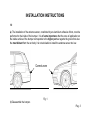
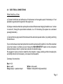
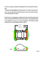
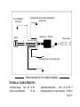
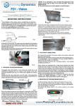
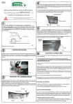
INSTALLATION INSTRUCTIONS
&
USER MANUAL
Parking sensor mod.
EPS-DUAL
- Installation instructions ................................. Pag. 3
- User Manual ................................................ Pag. 12
- Electric schematic ....................................... Pag. 15
- Kit components ........................................... Pag. 16
EPS-DUAL can be installed on front or on back bumper.
The sistem is strictly a driver assistance device, and should not be relied upon as a
security device or a substitute for safe driving practices.
Use common sense when reversing, and always follow recommended safe driving guidelines.
INSTALLATION INSTRUCTIONS
1.0
a) The installation of the antenna sensor, constituted by an aluminium adhesive ribbon, must be
performed to the inside of the bumper. It is of some importance that the zone of application on
the inside surface of the bumper corresponds to the higher part as regards the ground but also
the most distant from the car body. It is not advisable to install the antenna sensor too low.
Correct zone
Fig. 1
b) Disassemble the bumper.
Pag. 3
2. STARTING PROCEDURE
FRONT BUMPER INSTALLATION
REAR BUMPER INSTALLATION
a) Locate a passage where, from the outside at the
extremity of the bumper,it is possible to take the ECU
harness in the engine compartment driver's side.
a) Identify on the car body the zone close to
the extremity of the bumper and, on the side
where it is present the back-gear lamp, a
possible hole of passage toward the interns
of the trunk in order to carry out the
connections cable from the electronic unit.
b) Through the individuated passages route the connections cable inside the trunk or the engine
van leaving the ECU outside. (Fig. 2)
Central module
+ harness
Central module + harness
Fig. 2
Pag. 4
3.0 MOUNTING THE ECU AND ANTENNA SENSOR
Thoroughly clean with alcohol or nitro solvent (be carefull not to use antiadhesive detergent) the
inner surface of the bumper of the zone previously identified (see Fig.1) on which will be applied the
antenna sensor and the central unit.
Starting from the zone where the central unit + harness will be fixed, start applying the adhesive
aluminum tape (antenna sensor) practicing a good pressure to make it well adhere to the inner
surface of the bumper *.
Cable
Antenna sensor
Central unit (ECU)
Bumper
Fig. 3
Pag. 5
When the antenna sensor has been attached, covering the whole of the bumper from left to right, the
excess length is cut off. Place a piece of the included sticking material at either ends of the antenna
sensor to ensure a secure fixing onto the bumper. Its recommended (but not essential) to cover the
antenna with a black anti-rust protection paint that is applied to the underneath of a car chassis or
similar to protect from the elements (do not use silicon paste).
* NOTE:
1) It 'advisble to start and finish the application of the antenna sensor tape et about 15 cm
from the end of the bumper (Fig. 3).
2) The sensor antenna can not be applied on metal bumpers.
Sticking material
Antenna sensor
15cm
Pag. 6
Connect the small fastoned cable of the ECU to the antenna sensor. Apply a piece of sticking
material on the unit and place it on the bumper by a strong pressure. It is advisable to use the same
material to cover and block the connection (Fig. 5).
Replace the bumper and pull the wiring inside the luggage compartment or engine compartment in
order not to leave excess cable outside.
Sticking material
Central unit (ECU)
Fig. 5
Pag. 7
4.0
ELECTRICAL CONNECTIONS
FRONT INSTALLATION
a) Connect both black and white wires of the harness to the negative pole of the battery or if not
possible to a good electrical ground in the engine van.
b) Using a normal electrical wire prolong the red wireof the harness bringing it inside the car in order
to connect it, through the push-button activation, to a 12 Volt subkey (the system is so activated
pressing the button).
c) Connect the two gray leads of the harness to the extension speaker cable (no polarity) and bring
it inside the car.
If your vehicle has a metal crash protection bar and the antenna will be within 2 cm's of this metal bar
(once the bumper is re-fitted) you can choose the HIGH SENSITIVTY option on the connection
cables (harness) in order to prevent any reduction in detection range.
We suggest to carry out tests to determine the detection range, pointing out that increasing the
sensitivity where it is not necessary, can cause more false alerts.
Summary of connections:
Red: +12 V
Nero: earth
Gray (couple) : speaker output
White: to the earth
Yellow: to the earth for high sensitivityl
Pag. 8
REAR INSTALLATION
a) Connect the red lead of the harness to the positive cable that feeds the reversing lamp.
b) Connect the black lead of the harness to the earth of the reversing lamp.
-- IT ADVISABLE NOT TO CONNECT TO ANY OTHER POINT OF EARTH ON THE CHASSY OF
THE CAR -c) Connect the two gray leads of the harness to the extension speaker cable (no polarity) and bring
it inside the car.
if your vehicle has a metal crash protection bar and the antenna will be within 2 cm's of this metal bar
(once the bumper is re-fitted) you can choose the HIGH SENSITIVTY option on the connection
cables (harness) in order to prevent any reduction in detection range.
We suggest to carry out tests to determine the detection range, pointing out that increasing the
sensitivity where it is not necessary, can cause more false alerts.
Summary of connections:
Red: +12 V of rear lamp
Nero: earth
Gray (couple) : speaker output
White: not connected
Yellow: to the earth for high sensitivityl
Pag. 9
5. MOUNTING THE SPEAKER
a) Mount the EPS-DUAL speaker using the included adhesive mount in a proper place in order
to ensure a good perception of sound by the driver.
b) Connect the extension wire to the speaker through its plug-in connector.
6. FINAL TESTING PROCEDURE
a) Turn on the key, insert the back gear (press the push-button for thel front).
In a fraction of secon the control unit performs a check of the functionality of the system and, if
everything has been done correctly, the transducer emits an acoustic sound of "OK" (two notes in
rapid succession when installed in the rear and a note if installed before ). Once you have this signal
the system becomes operational.
Possible problems and their solutions
1. If the acoustic transducer does not emit any signal check all the connections.
2. If the transducer emits an audible warning signal consisting of 2 notes (one high and one low)
repeated 3 times) check the connection of the sensor antenna to the ECU.
b) Starting from about 1 meter away from the center of the bumper, slowly approach both hands to
simulate a parking maneuver. At a distance of about 60/70 cm will be heard the first acoustic signals
whose repetition rate will increase at the decreasing distance to become a fast intermittent sound
fast and then a contnuous higher frequency sound at about 10-15 cm from the bumper.
Pag. 10
WARNING: For a correct simulation reset the system every time you approach.
c) If the system proves to work properly, you can remount the bumper.
Nota: EPS-DUAL starts to give the signaling only when the vehicle is being approached to the
obstacle; a fixed object in front of the bumper, for instance the hauls hook and a bull bar or the sides
walls of a car box, is not signaled and it is not bothered the normal operation of the device.
Pag. 11
USER MANUAL
1.OPERATING PRINCIPLE
EPS-DUAL is an innovative parking sensor that uses low energy electromagnetic waves and is
able to detect the approach of any kind of obstacle .
The activation of the device isobteined by the insertion of the back gear or by pressing the
activation button (if installed on front bumper) and confirmed by a signal of "OK". Once activated, the
EPS-DUAL generates around the bumper, on which is installed, a protection zone (Fig. 6). When
any obstacle present in the protection zone, tends to approach the bumper you will hear a series of
beeps.
WORKING EXAMPLE
A) As soon as the EPS-DUAL is activated the control functionality of the system is carried out in a
fraction os second.
In case of anomalies the speaker emits an audible warning signal consisting of 2 notes (one high
and one low) repeated 3 times. If this happens check the antenna connection to the ECU.
If the check is OK you hear a signal of two notes in quick succession to confirm the proper
functioning of the system. If installedon the front bumper the OK signal consists of a single note.
B) When approaching an obstacle the system activates the acoustic signal at a distance
between the bumper and obstacle (measured in the central area of the bumper) of about 60 / 70
cm with 3 types of sounds:
Pag. 12
1) an increase in sequence of "BIP"(alert) inform the driver that an obstacle is approaching.
2) intermittent sounds of fast repetition rate (alarm) when the obstacle comes close to the
bumper at a distance between 15 and 30 cm.
3) continuous sound at a more acute frequency (risk of contact) when an obstacle is very
close to the bumper (10-15 cm)
Note
- The distances will vary depending on the size of the obstacle, and correspond to the central
zone of the bumper; on the lateral edges the distances will decrease is less (see Figure 6)
- If EPS-DUAL is installed on the front the tone of sounds is at a higher frequency in order
tomore easily distinguish from the back.
WARNING
1. In presence of rain or high moisture weather, the system reduces his sensibility automatically in
order to eliminate a part of false alarms that could be given by movement of water on the bumper. In
this situation the system could give only the last two frequency signals ( alarm and risk of contact).
(Fig. 6).
Pag. 13
2. As soon as the system is activated an acknowledgement of the surrounding of the bumper is
made.
Consequently it is very important, during testing operation, not to switch on the system while
you are very close to the central unit and antenna sensor in order not to have false information
on the working capability of the system.
During the test you must also take into consideration the fact that, after the first approach to the
bumper, any subsequent APPROACH without first reset the system , can give false interpretations
of the functionality of the sensor due to special characteristics of the EPS-DUAL software
specifically done to reduce false signaling in the rainy conditions.
ALERT SIGNAL
ALARM SIGNAL
RISK OF CONTACT
(Fig. 6)
Pag. 14
High sensitivity (front and back installation)
(yellow lead)
Front installation
(white lead)
Central unit + harness
Buzzer
Antenna sensor
-
+
To back gear lamp or push-button switch
Block schematic for front or back installation
TECHNICAL CHARACTERISTICS
- Operating range
from 9,5 to 18V
- Max current absorption
70 mA
- Operating temperature
from -20 to +90 °C
- Averange distance to begin detection 70-80 cm
Pag. 15