1
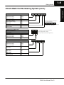
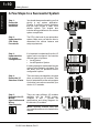
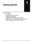
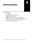
Getting Started
In This Chapter. . . .
— Introduction
— DL305 System Components
— DirectLOGIC™ Part Numbering System
— A Few Steps to a Successful System
11
1--2
Getting Started
Getting Started
Introduction
The Purpose of
this Manual
Thank you for purchasing our DL305 family of automation products. This manual
shows you how to install the equipment, and it also helps you understand the system
operation characteristics.
Since we constantly try to improve our product line, we occasionally issue addenda
that document new features and changes to the products. If an addendum is
included with this manual, please read it to see which areas of the manual or product
have changed.
Who Should Read
this Manual
If you understand PLC systems our manuals will provide all the information you need
to get and keep your system up and running. We will use examples and explanations
to clarify our meaning and perhaps help you brush up on specific features used in the
DL305 system. This manual is not intended to be a generic PLC training manual, but
rather a user reference manual for the DL305 system.
Where to Begin
If you are in a hurry and already understand the DL305 system please read Chapter
2, Installation and Safety Guidelines, and proceed on to the chapter pertaining to
your needs. Be sure to keep this manual handy for reference when you run into
questions. If you are a new DL305 customer, we suggest you read this manual
completely so you can understand the wide variety of products, configurations, and
procedures used with the DL305 family of products. We believe you will be
pleasantly surprised with how much you can accomplish with AutomationDirect
products.
If you’re really in a hurry, check out Appendix A. This appendix has a quick start that
will show you how to quickly connect and program a very simple system.
Supplemental
Manuals
Depending on the products you have purchased, there may be other manuals that
are necessary for your application. If you have purchased analog I/O, specialty
modules, or DirectSOFT, or you will be using remote I/O or networking, you will want
to supplement this manual with the manuals written for these products.
DL305 User Manual, Rev. D
Getting Started
1--3
DL305 User Manual, Rev. D
Getting Started
How this Manual is Ch 1: Getting Started -- provides an overview of all the components that can be
used to make up one or many DL305 systems. This chapter shows the basic
Organized
concepts of how the pieces fit together. It also explains the DL305 part numbering
system, which will help you quickly identify the various types of modules.
Ch 2: Installation and Safety Guidelines -- shows you how to prepare for system
installation, and gives you guidelines for providing a safe environment for your
personnel and process. Be sure to read this chapter so potential safety problems
can be avoided. In this chapter you will find topics you must consider when installing
a system, the environmental specifications, component dimensions, safety
guidelines, installation guidelines, etc.
Ch 3: DL330/DL330P/DL340 CPU Specifications -- provides details of each of the
DL305 CPUs. This chapter contains the operating specifications for the CPUs,
detailed information on the different types of program storage media available, and
some basic procedures needed to get the CPU ready for programming.
Ch 4: System Configuration, Bases and Expansion Bases -- provides selection
and installation criteria for Local I/O and Local Expansion I/O. This chapter also
discusses the system power budget, which is an important part of the planning and
installation process.
Ch 5: I/O Module Selection Criteria -- contains specific considerations which affect
I/O selection such as sinking, sourcing, and temperature derating characteristics.
Ch 6: Discrete Input Modules -- explains each term you will find on our specification
sheets, provides specifications, wiring diagrams and derating curves (where
applicable) for the DL305 Discrete Input Modules.
Ch 7: Discrete Output Modules -- explains each term you will find on our
specification sheets, provides specifications, wiring diagrams and derating curves
(where applicable) for the DL305 Discrete Output Modules.
Ch 8: System Operation -- explains how the DL305 CPUs control the system
operation. This includes information on I/O updates, application program execution
and memory structure.
Ch 9 : RLL Programming Concepts -- explains the basic concepts used in RLL
programming.
Ch 10: RLL PLUS Programming Concepts -- explains the basic concepts used in
the RLL PLUS programming. This programming method greatly reduces program
design time and simplifies machine startup and troubleshooting.
Ch 11: Instruction Set -- explains how each individual instruction operates.
Ch 12: RLL PLUS Instruction Set -- explains the instructions used with the DL330P
CPU. It also shows some instructions that operate differently with this CPU.
Ch 13: Maintenance and Troubleshooting -- is a guide designed to aid you in
diagnosing, repairing and avoiding system problems.
Appendices A -- D -- there are several appendices referred to throughout the
manual. These include things such as a quick start, error code listing, instruction
execution times, etc.
We realize even though we strive to be the best, we may have arranged our
Technical
information in such a way you cannot find what you are looking for. If you need
Assistance
assistance, please, call us at 1--800--633--0405. Our technical support group is glad
to work with you in answering your questions. They are available weekdays from
8:00 a.m. to 6:00 p.m. eastern standard time. If you find a problem with any of our
products, services or manuals, please fill out and return the Suggestions card
included with this manual.
1--4
Getting Started
Getting Started
DL305 System Components
The DL305 product family is one of the most versatile and widely accepted PLCs
used for small control applications. These CPUs are small yet powerful. Their
modular design and expansion capability blend well with todays fast moving
industry. The following is a summary of the major DL305 system components.
CPUs
There are three CPUs in this product line, the DL330, the DL330P and the new
DL340. Details of these CPU are covered in Chapter 3, DL330/DL330P/DL340 CPU
Specifications.
Bases
Three base sizes are available in the system: 5 slot, 8 slot and 10 slot.
I/O Configuration
The DL330 and DL330P CPUs support up to 128 local I/O and 176 local expansion
I/O. The DL340 supports 136 local I/O and 184 local expansion I/O. Each of these
I/O configurations is explained in Chapter 4, Bases and Expansion Bases and I/O
Configuration.
I/O Modules
The DL305 has one of the most diverse I/O module selections in the industry. A
complete range of discrete modules which support 24 VDC, 125 VDC, 110/220 VAC
and up to 10A relay outputs are offered. The analog modules provide 12 bit
resolution and several selections of input and output signal ranges (including
bipolar). The specialty modules include 10KHz high speed input, thermocouple,
general purpose communication, and more.
Programming
Methods
There are two programming methods available, RLL (Relay Ladder Logic) and
RLL PLUS. RLL PLUS combines the added feature of flow chart programming (stages)
to the standard RLL language. RLL PLUS is only available for the DL330P CPU. All of
the DL305 CPUs support RLL programming. DirectSOFT supports both RLL and
RLL PLUS programming. Two handheld programmers are available, the D3--HPP
which supports RLL PLUS and the D3--HP which only supports RLL programming.
The key pads for each handheld programmer differ, so it is recommended the
handheld programmer that directly supports your CPU be used for programming.
DirectSOFT
Programming for
Windows™
The DL305 can be programmed with one of the most advanced programming
packages in the industry — DirectSOFT. DirectSOFT runs under Windows and
supports many of the windows based features you are already familiar with such as
cut and paste between applications, point and click editing, viewing and editing
multiple application programs at the same time, browsers, etc. DirectSOFT
universally supports the DirectLOGIC CPU families. This means you can use the
same DirectSOFT package to program DL205, DL305, DL405 or any new CPUs we
add to our product line. There is a separate manual that discusses DirectSOFT
programming software.
Handheld
Programmer
All DL305 CPUs have a built-in programming port for use with the handheld
programmers (D3--HPP and D3--HP). Handheld programmers can be used to
create, modify and store programs to cassette tape, as well as debug your
application program. There is also a separate manual that discusses the DL305
Handheld Programmers.
DL305 System
Diagrams
The next page shows a generic example highlighting the major components and
configurations of the DL305 system. The following two pages highlight the specific
components which can be used to build your system.
DL305 User Manual, Rev. D
1--5
Getting Started
Computer Controlled I/O
Packaging
Conveyors
Elevators
Industry Standard Computer I/O Protocol
OPTOMUX™ (Serial RS422/485)
PAMUX™ (Parallel)
Handheld Programmer
DL305
1.5ft
(.05m)
Getting Started
Machine Control
DL305
1.5ft
(.05m)
RS232C
(max.50ft/16.2m)
RS422/485
DL305
DL305
Programming or
Computer Interface
Computer Interface
with OPTOMUX™ Driver
Networking
DCM
Programming or
Computer
Interface
Operator Interface
DL405
Handheld Programmer
RS422
RS232C
(max.50ft/16.2m)
DL305
RS232C/422
Convertor
(max. 4.6ft / 1.5m)
RS232C
(max.50ft/16.2m)
DL305
RS232C/422
Convertor
DL305
RS232C/422
Convertor
DL305 User Manual, Rev. D
Getting Started
1--6
Getting Started
DirectLOGIC
DC INPUT
8pt
16pt
16pt
16pt
24 VDC
24 VDC
5-24 VDC
12-24 VDC
DL305 Family
AC INPUT
AC/DC INPUT
8pt 110 VAC
16pt 110 VAC
8pt 24 VAC/DC
16pt 24 VAC/DC
PROGRAMMING
Handheld Programmer for RLL CPUs
Handheld Programmer for RLL PLUS CPUs
DirectSOFT Programming for Windows™
CPUs
ASCII BASIC Modules
RS232C / RS422 / RS485
Built-in Radio Modem
Built-in Telephone Modem
Program Memory 64K/128K
DL330
3.7K RAM RLL Programming
DL330P
3.7K RAM RLL PLUS Programming
DL340
3.7K RAM RLL Programming
and 2 Built-in RS232C Ports
DL330/DL330P/DL340 EPROM
Memory Chips
BASES
5 Slot Base w/Expansion Capability,
110/220 VAC P/S
5 Slot Base w/Expansion Capability,
24 VDC Supply
8 Slot Base w/Expansion Capability,
110/220 VAC P/S
10 Slot Base w/Expansion Capability,
110/220 VAC P/S
DL305 User Manual, Rev. D
Getting Started
1--7
Getting Started
DC OUTPUT
RELAY OUTPUT
AC OUTPUT
8pt 5--24 VDC
16pt 5--24 VDC
4 pt
8pt
16pt
16pt
8pt
8pt
8pt
16pt
110--220 VAC
110--220 VAC
12--220VAC
15--220VAC
4A/pt
5A/pt
10A/pt
2A/pt
ANALOG
4ch
8ch
16ch
2ch
4ch
8ch
INPUT
INPUT
INPUT
OUTPUT
OUTPUT
TEMPERATURE
TRANSDUCER INPUT
8ch THERMOCOUPLE
INPUT
SPECIALTY CPUs
Bridge CPU to connect
to host w/OPTOMUX™ Driver
Bridge CPU w/FACTS
Extended Basic Programming
Bridge CPU to connect to
High-speed PAMUX™
compatible host
SPECIALTY
MODULES / UNITS
NETWORKING
RS232C Data Communication Unit
RS422 Data Communication Unit
MODBUS® Slave Module
MODBUS® Slave Module
w/Radio Modem
Universal connector:
RS232C / RS422/485 Convertor
8pt INPUT Simulator
1pt High Speed Counter
PROM Writer Unit
Filler Module
DL305 User Manual, Rev. D
1--8
Getting Started
Getting Started
DirectLOGIC Part Numbering System
As you examine this manual, you’ll notice there are many different products available. Sometimes it is
difficult to remember the specifications for any given product. However, If you take a few minutes to
understand the numbering system, it may save you some time and confusion. The charts below show how
the part numbering systems work for each product category. Part numbers for accessory items such as
cables, batteries, memory cartridges etc. are typically an abbreviation of the description for the item.
CPUs
Specialty CPUs
Product family
D4--
440DC
D3--
05B
D4--
16
N
D
2
D3--
16
N
D
2
--1
D2/F2
D3/F3
D4/F4
Class of CPU / Abbreviation
230...,330...,430...
Denotes a differentiation between
Similar modules
--1, --2, --3, --4
Bases
Product family
DC
D2/F2
D3/F3
D4/F4
Number of slots
##B
Type of Base
DC or empty
Discrete I/O
DL205 Product family
y
D2/F2
/
DL305 Product family
y
D3/F3
DL405 Product family
D4/F4
Number of points
04/08/12/16/32
Input
p
N
Output
p
T
Combination
C
AC
A
DC
D
Either
E
Relay
Current Sinking
g
R
1
Current Sourcing
g
2
Current Sinking/Sourcing
3
High
g Current
H
Isolation
S
Fast I/O
Denotes a differentiation between
Similar modules
F
--1, --2, --3, --4
DL305 User Manual, Rev. D
F
--1
1--9
Getting Started
DirectLOGIC Part Numbering System (cont.)
F3--
DL205 Product family
y
D2/F2
/
DL305 Product family
y
D3/F3
DL405 Product family
D4/F4
Number of channels
02/04/08/16
Input
p ((Analog
g to Digital)
g )
AD
Output
p ((Digital
g
to Analog)
g)
DA
Combination
Isolated
AND
S
Denotes a differentiation between
Similar modules
--1, --2, --3, --4
Communication and Networking,
Special I/O and Devices
Programming
DL205 Product family
D2/F2
DL305 Product family
D3/F3
DL405 Product family
D4/F4
Name Abbreviation
see example
CoProcessors and ASCII BASIC Modules
DL205 Product family
y
D2/F2
/
DL305 Product family
y
D3/F3
DL405 Product family
D4/F4
CoProcessor
CP
ASCII BASIC
AB
64K memoryy
64
128K memoryy
128
512K memory
512
Radio modem
R
Telephone modem
T
04
AD
S
Getting Started
Analog I/O
--1
Altermate example of Analog I/O
using abbreviations
F3--
08
THM
--n
note: --n indicates thermocouple type
such as: J, K, T, R, S or E
D4--
DCM
D3--
HSC
HSC (High Speed Counter)
D3--
HPP
HPP (RLL PLUS Handheld Programmer)
F4--
CP
DCM (Data Communication Module)
128
-- R
DL305 User Manual, Rev. D
1--10
Getting Started
Getting Started
A Few Steps to a Successful System
Step 1:
Review the
Installation
Guidelines
You should always make safety your first
priority in any system application.
Chapter 2 provides several guidelines
that will help provide a safer, more
reliable system. This chapter also
includes wiring guidelines for the various
system components.
Step 2:
Understand the
CPU Setup
Procedures
The CPU is the heart of your automation
system. Make sure you take the time to
understand the various features and
setup requirements.
Step 3:
Understand the
I/O System
Configurations
It is important to understand how the I/O
system can be configured. You have two
different types of systems.
S Local System
S Local Expansion System
It is also important to understand how the
system Power Budget is calculated. This
can affect your I/O placement and/or
configuration options.
Step 4:
Review the I/O
Selection Criteria
There are many considerations involved
when you select your I/O modules. Take
time to understand how the various types
of electrical connections can affect your
choice of I/O modules.
Step 5:
Determine the I/O
Module
Specifications and
Wiring
Characteristics
There are many different I/O modules
available with the DL305 system.
Chapters 6 and 7 provide the
specifications and wiring diagrams for
the discrete I/O modules.
NOTE: Specialty modules have their
own manuals and are not included in this
manual
DL305 User Manual, Rev. D
Emergency
Stop
030 020 010 000
to
to
to
to
037 027 017 007
130 120
to
to
137 127
110 100
to
to
117 107
C
P
U
060 050 040
to
to
to
067 057 047
160 150 140
to
to
to
167 157 147
DL305
DL305
1--11
Getting Started
Step 7:
Review the
Programming
Concepts
Step 8:
Choose the
Instructions
Before you begin to enter a program, it is
very helpful to understand how the
DL305 system processes information.
This involves not only program execution
steps, but also involves the various
modes of operation and memory layout
characteristics.
All control systems differ in some areas.
The DL305 CPUs offer two different
types
of
programming.
RLL
programming available for all the DL305
CPUs, uses conventional ladder
diagram type solutions for many
application problems.
RLL PLUS is available for the DL330P
CPU. This method of programming
greatly reduces the program design time
and makes program troubleshooting and
machine startup considerably easier.
Once you have installed the system and
understand the theory of operation, you
can choose from a diverse instruction set
to implement your application.
Power up
Getting Started
Step 6:
Understand the
System Operation
Initial Mode Setting
Initialize memory
RLL Programming
output
010
input
000
RLL PLUS (flowchart) Programming
ISG
S0
SG
S1
J
TMR
T1
K 30
CNT
CT3
K10
Step 9:
Understand the
Maintenance and
Troubleshooting
Procedures
Many things can happen on the factory
floor. Switches fail, batteries need to be
replaced, etc. In most cases, the majority
of the troubleshooting and maintenance
time is spent trying to locate the problem.
Chapter 13 provides some information
that will help you quickly identify
problems, so you can look like a hero if
you take time to understand them.
DL305 User Manual, Rev. D