1
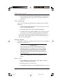
ConfigEd Lite DC Applications Pack version 5 for Windows® 3.x/95/98/NT User Manual © Copyright Eurotherm Drives, Inc. 2003 All rights strictly reserved. No part of this document may be stored in a retrieval system or transmitted in any form. Although every effort has been taken to ensure the accuracy of this manual, it may be necessary, without notice, to make amendments or correct omissions in this document. Eurotherm Drives, Inc. cannot accept responsibility for damage, injury, or expenses resulting therefrom. Procedures detailed in this manual are designed to be performed by personnel with sufficient training and/or experience. Only sufficiently qualified personnel familiar with the construction and operation of industrial drive equipment and the dangers of working with high-voltage electrical systems should attempt installation, adjustment, operation, or service of this equipment. Failure to follow these guidelines could result in damage to the equipment and severe injury or loss of life to personnel. If you are unsure of your qualifications or do not understand certain procedures in this manual, contact Eurotherm Drives Customer Service for assistance. Before attempting any procedures in this manual, including installation, verify that the model numbers on the product and in this manual match. If any discrepancy is found, contact Customer Service immediately. Printed in the United States of America title.p65 1 HA352747A003 Issue 4 1/23/2003, 4:29 PM ConfigEd Lite DC Applications Pack Contents Chapter 1 INTRODUCTION Software Compatibility ..................................................................................................... 1 - 1 Applications ................................................................................................................................ 1 - 1 Chapter 2 OPEN-LOOP WINDER (CPW) Description ................................................................................................................................... 2 - 2 Turret Winder Applications .................................................................................. 2 - 3 Input Signal Descriptions ................................................................................................... 2 - 4 Startup Procedure ................................................................................................................... 2 - 6 Speed Mode ...................................................................................................................... 2 - 6 Tension Mode ................................................................................................................... 2 - 7 Unwind ................................................................................................................................... 2 - 9 Rewind .................................................................................................................................... 2 - 9 Chapter 3 CLOSED-LOOP WINDER (SPW) Description ................................................................................................................................... 3 - 1 Loadcell Applications ............................................................................................... 3 - 2 Dancer Position Applications ............................................................................. 3 - 2 Turret Winder Applications .................................................................................. 3 - 3 Input Signal Descriptions ................................................................................................... 3 - 3 Startup Procedure ................................................................................................................... 3 - 5 Speed Mode ...................................................................................................................... 3 - 5 Tension Mode ................................................................................................................... 3 - 6 Unwinds ................................................................................................................................ 3 - 8 Chapter 4 SECTION CONTROL (SC) Control Modes .......................................................................................................................... 4 - 1 Additional Features ............................................................................................................... 4 - 4 Input Signal Descriptions ................................................................................................... 4 - 5 Startup Procedure ................................................................................................................... 4 - 6 Other Settings ............................................................................................................................ 4 - 8 Other Features ........................................................................................................................... 4 - 8 Appendix A Simple Winder Equations Appendix B Template Configuration Drawings ConfigEd Lite DC Applications Pack toc.p65 1 Cont. 1 1/23/2003, 4:29 PM Cont. 2 toc.p65 ConfigEd Lite DC Applications Pack 2 1/23/2003, 4:29 PM Chapter 1 - Introduction Chapter 1 INTRODUCTION This manual describes the use of the template configurations shipped with the ConfigEd Lite DC Applications pack. There are three different types of templates for each drive and firmware version. They are: Current Programmed Winder (CPW) This configuration is an open loop center winder control using torque clamps for tension control. Speed Programmed Winder (SPW) This configuration is a closed-loop center winder control using either loadcell or dancer feedback for tension control. Section Control (SC) This configuration provides all the features required by a line drive section to perform Draw, Ratio, Loadcell, Dancer position, or Torque control. Templates with the .SPD extensions are to be used with the 590SP single phase digital drive Templates with the .590 extensions and version 3 or 4 are to be used with the 590D three phase drives. Templates with the 590 extensions and version 5 or 7 are to be used with the 590+ three phase drives. SOFTWARE COMPATIBILITY Use this applications pack with ConfigEd Lite version 5.17 or later. The 590 controller must be firmware version 3.2 or later. All 590SP and 590+ versions are supported. NOTE. Users should be familiar with using and configuring the 590 controller and ConfigEd Lite. APPLICATIONS Five function blocks are used to add winder and section control capability to the 590. They are DIAMETER CALC., TAPER CALC., TORQUE CALC., SETPOINT SUM 2, and PID. They can be used as required for other ConfigEd Lite DC Applications Pack C1-intro.p65 1 1-1 1/23/2003, 4:29 PM Chapter 1 - Introduction applications. For detailed descriptions of these function blocks, see the 590 (+) product manual. These configurations attempt to standardize the functions of the control terminals. Figure 1.1 lists the types and functions of the terminals when using Current Programmed Winder, Speed Programmed Winder, or Section Control configurations described in this manual. WARNING! The control terminals of the drive are fully isolated from all power circuits and should not be connected to other nonisolated circuits. 'ULYH 6RIWZDUH 7HUPLQDO 5HIHUHQFH $ $QDORJ,QSXW &XUUHQW 6SHHG 3URJUDPPHG 3URJUDPPHG :LQGHU)XQFWLRQ :LQGHU)XQFWLRQ 3UHVHW'LDPHWHU 3UHVHW'LDPHWHU 6HFWLRQ&RQWURO )XQFWLRQ 'UDZ5DWLR 7HQVLRQ'DQFHU $ $QDORJ,QSXW 1RW&RQQHFWHG 1RW&RQQHFWHG )HHGEDFN $ $QDORJ,QSXW /LQH6SHHG5HIHUHQFH /LQH6SHHG5HIHUHQFH /LQH6SHHG5HIHUHQFH $ $QDORJ,QSXW 7HQVLRQ6HWSRLQW 7HQVLRQ6HWSRLQW 7HQVLRQ6HWSRLQW $ $QDORJ,QSXW 7DSHU6HWSRLQW 7DSHU6HWSRLQW 7HQVLRQ)HHGEDFN $ $QDORJ2XWSXW 5HHO6SHHG2XWSXW 'DQFHU/RDGLQJ2XWSXW 6HFWLRQ6SHHG $ $QDORJ2XWSXW 'LDPHWHU2XWSXW 'LDPHWHU2XWSXW 7RWDO6SHHG6HWSRLQW & -RJ 7HQVLRQ(QDEOH -RJ 7RUTXH0RGH & 'LJLWDO,QSXW 2YHUZLQG 2YHUZLQG 5HYHUVH & 'LJLWDO,QSXW 3UHVHW(QDEOH 3UHVHW(QDEOH 1RW&RQQHFWHG & 'LJLWDO,QSXW 1RW&RQQHFWHG 7HQVLRQ(QDEOH 3,'(QDEOH Figure 1.1 - Terminal Functions ConfigEd Lite DC Applications Pack 1-2 C1-intro.p65 2 1/23/2003, 4:29 PM Chapter 2 Open-Loop Winder Chapter 2 OPEN-LOOP WINDER (CPW) The cpw_v(4,5,7).590 configuration provides standard features used in center winder applications including: diameter calculation with memory and preset, tension and taper, loss compensation, and over/under winding. It can control unwinds or rewinds for single-spindle and turret winders. The configuration uses four function blocks in the SPECIAL BLOCKS menu of the 590 drive; DIAMETER CALC., TAPER CALC., TORQUE CALC., TENSION & COMP, RAISE/LOWER and SETPOINT SUM 2. NOTE. Only the cpw_v(4,5,7).590 configuration supports jog and field weakening. 590SP's and older versions of the 590 do not support jog and extended speed ranges using field weakening. A current programmed winder provides constant tension center winder control by programming the motor armature current. The tension control is openloop; that is, it does not use a dancer or loadcell feedback signal. The drive maintains constant tension by controlling motor torque. It keeps the torque proportional to the tension demand and compensates for changing roll diameter with additional compensations for frictional losses. NOTE. For accurate tension control, frictional losses must be small (and repeatable) compared to the torque required to provide web tension. Figure 2.1 - Unwind Application 2 - 1 ConfigEd Lite DC Applications Pack C2-cpw.p65 1 1/23/2003, 4:29 PM Chapter 2 Open-Loop Winder DESCRIPTION Figures 2.1 and 2.2 show typical rewind and unwind applications. The diameter is reset before starting a new roll by using terminal A2, EXTERNAL DIAMETER PRESET, for the diameter setting and C7, PRESET ENABLE, to select the preset diameter. The drive starts when terminal C3, RUN, is set ON. Setting terminal C4 to ON selects jog mode. For TENSION ENABLE, both C3 and C4 should be ON. Once the line gets above a minimum speed the diameter calculator begins calculating the roll diameter. In tension mode, an overspeed (underspeed for unwinds) is added to saturate the speed loop because the web holds the winder at line speed. With the speed loop saturated, the drive is current limited by the torque demand. If the web breaks, the winder increases to the speed loop limits, preventing a runaway. Terminal C6, OVERWIND, changes the polarity of the torque demand and overspeed for overwinding or underwinding. For unwinds, set Value for True = 0.00% and Value for False = 0.01%. TAPER CALC. uses signals from terminals A5, TENSION SETPOINT, and A6, TAPER SETPOINT, to produce the tension demand. SETPOINT SUM 2 multiplies the tension demand by diameter to produce the torque demand. The torque demand is then combined with compensations for frictional losses to produce the final torque used to control the drive. Loss compensations have static and dynamic components. The static part is a fixed value for overcoming static loss or stiction. The dynamic part is pro- Figure 2.2 - Rewind Application ConfigEd Lite DC Applications Pack 2 - 2 C2-cpw.p65 2 1/23/2003, 4:29 PM Chapter 2 Open-Loop Winder portional to speed. It compensates for the dynamic loss or windage. Figure 2.3 shows the static and dynamic compensations. The combined losses increase torque demand in rewinds and decrease it in unwinds. TORQUE CALC. uses the torque demand from SETPOINT SUM 2 Figure 2.3 - Friction Loss to control the current limits. It Compensation controls the positive or negative current limits depending on the selection of overwinding or underwinding. The current limit is only controlled by the torque demand when tension mode is enabled, otherwise the current limit is at the normal maximum value for speed mode. Turret Winder Applications Turret winders use two spindles to transfer the web from one spindle to the other without stopping the line. Each spindle requires its own drive. An unwind splices from the emptying roll to a new, full roll. A rewind transfers the web from the full roll to a new core. To achieve this, the winders must operate in two modes, speed mode and tension mode. Speed mode is required to match the surface speed of the new core or new, full roll to the line speed for the splice. Tension mode is required after the splice or transfer. Before starting in speed mode, the operator sets the diameter to core for a rewind or to the diameter of the new roll for an unwind by entering the correct value in terminal A2, EXTERNAL DIAMETER PRESET. Setting C7, PRESET ENABLE, to ON keeps the diameter at the preset diameter until the transfer is completed. Then the spindle is started using terminal C3, RUN. The drive ramps up to the correct speed so the rolls surface speed matches the line speed. The splice or transfer can occur at that point. When the web is transferred to the new roll or core, tension mode is enabled by setting terminal C4 to ON and the old roll is stopped. At this point, C7 is set OFF to allow the diameter calculator to calculate the correct diameter. The new roll continues in tension mode until the next roll change. 2 - 3 ConfigEd Lite DC Applications Pack C2-cpw.p65 3 1/23/2003, 4:29 PM Chapter 2 Open-Loop Winder INPUT SIGNAL DESCRIPTIONS Line Speed Reference A line speed signal is required for the diameter calculator to work. It should be scaled to produce +10 volts at full speed and connected into terminal A4, LINE SPEED. If this signal comes from a source other than a Eurotherm Drives motor controller, it may need to be scaled and isolated. This signal passes through the RAMPS block and goes to the LINE SPEED INPUT of the DIAMETER CALC block. NOTE. It is very important that the web does not slip. If it does, the diameter calculation will not be accurate resulting in poor winder performance. Tension Setpoint The tension setpoint of 0 to +10 volts is connected to terminal A5, TENSION SP. Typically this signal could come from a potentiometer fed from the drives +10 volt terminal, B2. This signal is connected to the TENSION SPT input of the TAPER CALC block. If the serial communications option is installed, the tension setpoint could be generated by a PLC, or supervisory computer. Taper Setpoint A taper setpoint, if required, of 0 to +10 volts should be connected to A6, TAPER SETPOINT. The range of taper can be set by the MAX VALUE and MIN VALUE for the A6 terminal input. This signal is connected to the TAPER input of the TAPER CALC block. If the serial communications option is installed, the taper setpoint could be generated by a PLC, or supervisory computer. NOTE. The higher the TAPER SETPOINT setting the greater the reduction in tension as the diameter increases (negative taper). Tension Enable Connecting 24 VDC to terminal C3 and C4 selects tension mode. When used with a run signal at terminal C3, C4 adds an overspeed, TAKE UP 1 in ConfigEd Lite DC Applications Pack 2 - 4 C2-cpw.p65 4 1/23/2003, 4:29 PM Chapter 2 Open-Loop Winder the JOG/SLACK block, to saturate the speed loop. Set this to +5% for a rewind and -5% for an unwind. Jog Connecting 24V to C4, keeping C3 low, implements the jog function. Overwind/Underwind Digital input terminal C6, OVERWIND, selects the winding direction, ON for overwinding and OFF for underwinding. For a rewind, set VALUE TRUE = 0.01% and VALUE FALSE = 0.00%. For an unwind, set VALUE TRUE = 0.00% and VALUE FALSE = 0.01% Diameter Preset For a simple rewind, the only diameter preset required may be one core diameter. This diameter can be set directly by changing RESET VALUE in the DIAMETER CALC block in Config For an unwind or rewind using varying new core sizes or parent roll sizes, the diameter must be set for each roll. Terminal A2 is connected to the RESET VALUE parameter in the DIAMETER CALC block. A 0 to +10 volt signal at A2 now provides the preset where +10 volts is the full or maximum roll diameter. That signal can be generated by an operator potentiometer, an ultrasonic transducer that measures roll diameter, or another diameter input device. NOTE. The DIAMETER PRESET must be set accurately. The diameter calculator does not calculate diameter at zero speed. Poorly set preset diameters can cause large tension variations in the web when the machine is started. Preset Enable 24 VDC at digital input terminal C7 selects PRESET ENABLE. When ON, it loads the value of DIAMETER PRESET into the diameter memory. Current Limit CUR. LIMIT/SCALER is set to 200 percent. Set MAIN CURR. LIMIT to suit the application, normally 120 percent. 2 - 5 ConfigEd Lite DC Applications Pack C2-cpw.p65 5 1/23/2003, 4:29 PM Chapter 2 Open-Loop Winder STARTUP PROCEDURE The user will need the following information: Absolute minimum roll diameter Absolute maximum roll diameter Absolute maximum line speed Motor maximum speed at the smallest roll diameter and maximum line speed Speed Mode Initial Setup These steps customize the drive for the calibration phase. 1. Install the cpw_v(4,5,7).590 configuration using ConfigEd Lite. 2. Set MIN DIAMETER to the core as a percentage of full roll. If there is more than one core size, it should be set to the smallest; for example, if the smallest core is 3.5 inches and the maximum full roll is 42 inches, then MIN DIAMETER is: 3.5 / 42 * 100 = 8.33 percent 3. Set OVERWIND to ON by connecting +24 volts to terminal C6 4. Save the parameters. Calibration This section calibrates the drive in speed mode. 1. Connect 24 VDC to terminal C7, DIAMETER PRESET ENABLE, to force the diameter hold to stay on (this is for initial calibration only). 2. Ensure C4 is OFF (tension mode) and monitor SPECIAL BLOCKS:: DIAMETER CALC.:: DIAMETER to see that the diameter is preset to core. If the diameter does not equal the minimum diameter, momentarily jumper +24 volts to C7, DIAMETER PRESET ENABLE. 3. Start up the drive as described in Chapter 4 of the 590 DRV product manual; that is, AUTOTUNE the current loop, optimize the speed loop, etc. Use terminal A4, LINE SPEED REFERENCE, as the speed demand input. ConfigEd Lite DC Applications Pack 2 - 6 C2-cpw.p65 6 1/23/2003, 4:29 PM Chapter 2 Open-Loop Winder 4. Load an empty core into the winder and match the core surface speed to the line speed using the 590 encoder or tachometer calibration as appropriate. Field Weakening This is used for extended speed range motors, frequently used in winding applications. 1. Under SPEED FEEDBACK SELECT, ensure that the drive is set for encoder or analog tach feedback. 2. In the field Control block, enable FIELD WEAKENING 3. For MIN VALUE in the RAISE/LOWER block, enter the base speed of the motor as a percentage of maximum speed of the application. At this point the drive and winder should be functioning correctly in speed control. When starting up turret winders, repeat the above procedure for the second spindle. Tension Mode The winder is calibrated in two phases; first, the static losses are determined and then, the dynamic losses. WARNING! Some of the following procedures require manually turning or stopping the spindles. Any suggestions of turning or stopping the winder spindle by hand while the motor is energized should only be performed by experienced personnel who are capable of evaluating the potential hazards and who are totally satisfied that the procedure is safe. NOTE. Unwind applications require loss compensations to be negative. Static Losses 1. In the CURRENT LOOP menu, set the CUR. LIMIT/SCALER to 200% and enable BIPOLAR MODE. 2. Set tension enable, C3 and C4, to ON. 3. Set TENSION SETPOINT, A5, and TAPER SETPOINT, A6, to zero. 2 - 7 ConfigEd Lite DC Applications Pack C2-cpw.p65 7 1/23/2003, 4:29 PM Chapter 2 Open-Loop Winder 4. Start the winder with the tension enabled by connecting +24 volts into terminal C3, RUN. The winder should not turn because there is no tension demand and, as yet, no compensations. 5. Slowly increase STATIC COMP under TENSION & COMP until the spindle turns and then reduce it gradually until it just stops turning. Now the motor should have nearly enough current to make the spindle break away. It should be possible to start and stop the spindle by hand with very little effort. Dynamic Losses 6. Set JOG/SLACK::TAKE UP 1 to 100 percent and increase the tension setpoint signal. The spindle should run up to full speed. 7. Reduce the tension setpoint signal to 0.00% and monitor DIAGNOSTICS:: CURRENT DEMAND. Dial in a small amount of DYNAMIC COMP under TENSION & COMP. Now the motor should have just enough current to keep the spindle running. If the friction is increased slightly using light pressure on the shaft, it should be possible to reduce the speed and the spindle should maintain the reduced speed after removing the pressure. Check the loss compensation throughout the speed range. If the speed changes at high speeds, adjust DYNAMIC COMP; if the speed changes at low speeds, adjust STATIC COMP until they are optimized. 8. Reset JOG/SLACK:: TAKE UP 1 to 10 percent. 9. Set EXTERNAL PRESET ENABLE, C6, to OFF. 10. Save the parameters. Unwind After completing the initial start-up, verify the unwind is accurately tuned for all diameters and speeds by using the following procedure: 1. Web the line from the full roll. 2. Verify the diameter is preset to full roll. 3. Set TENSION SETPOINT to a suitable value for the web material. 4. Start the unwind. ConfigEd Lite DC Applications Pack 2 - 8 C2-cpw.p65 8 1/23/2003, 4:29 PM Chapter 2 Open-Loop Winder 5. Check the tension at standstill. 6. Start the line and check the running tension. As the roll builds down, verify the diameter calculator output is operating correctly. The line must be running above MIN SPEED for the diameter calculator to operate. Rewind After completing the initial start-up, verify the rewind is accurately tuned for all diameters and speeds by using the following procedure: 1. Fit an empty core. 2. Web the line and transfer onto the winder core. 3. Verify the diameter is preset to core. 4. Set TENSION SETPOINT and TAPER SETPOINT to suitable values for the web material. 5. Start the rewind. 6. Check the tension at standstill 7. Start the line and check the running tension. As the roll builds up, verify the diameter calculator output is operating correctly. The line must be running above MIN SPEED for the diameter calculator to operate. 2 - 9 ConfigEd Lite DC Applications Pack C2-cpw.p65 9 1/23/2003, 4:29 PM Chapter 2 Open-Loop Winder ConfigEd Lite DC Applications Pack 2 - 10 C2-cpw.p65 10 1/23/2003, 4:29 PM Chapter 3 - Closed-Loop Winder Chapter 3 CLOSED-LOOP WINDER (SPW) The spw_v(4,5,7).590 configuration for a speed programmed winder, SPW, provides closed-loop center winder control. It programs the motor speed using either loadcell or dancer feedback for tension control. This configuration provides standard features used in center winder applications including: diameter calculation with memory and preset, tension and taper, PID for loadcell tension or dancer position control, and over/under winding. It can control unwinds or rewinds for single-spindle and turret winders. The configuration uses four function blocks in the SPECIAL BLOCKS: DIAMETER CALC., TAPER CALC., SETPOINT SUM 2, and PID. DESCRIPTION Figures 3.1 and 3.2 show typical SPW applications. SPW applications use closedloop trim to modify the winder speed. Line speed is conditioned in RAMPS before being combined with the tension trim in SETPOINT SUM 2. The result, SPT. SUM OUTPUT, is scaled by DIAMETER and MIN DIAMETER in SETPOINT SUM 1 to produce the speed demand. TAPER CALC.:: TOT. TENS DEMAND uses inputs to terminals A5, TENSION SETPOINT, and A6, TAPER SETPOINT, to produce a diameter compensated tension demand. It produces either the tension setpoint for loadcell applications or dancer loading signal for dancer applications. TAPER SETPOINT is not used in unwind applications. Figure 3.1 - Unwind SPW Application with Loadcell Feedback ConfigEd Lite DC Applications Pack C3-spw.p65 1 3-1 1/23/2003, 4:29 PM Chapter 3 - Closed-Loop Winder Terminal C6, OVERWIND, switches the speed demand sign for overwinding or underwinding. The winder can change directions by changing the LINE SPEED signal at terminal A4 to the opposite sign. Loadcell Applications In loadcell applications, the controller attempts to keep the tension at the loadcell constant by varying the winder speed. The setting at terminal A5, TENSION SETPOINT, sets the desired loadcell tension. In TAPER CALC., the tension setpoint is compensated for diameter and taper. The output, TOT. TENS DEMAND, is the PID setpoint signal at PID:: INPUT 1. PID compares the setpoint, PID:: INPUT 1, with TENSION FEEDBACK from terminal A3. The output, PID OUTPUT, is the tension loop trim used in SETPOINT SUM 2. Dancer Position Applications In dancer position applications, the controller attempts to keep the dancer stationary by varying the winder speed. TAPER CALC. uses signals from terminals A5, TENSION SETPOINT, and A6, TAPER SETPOINT, to produce the dancer loading. Dancer loading affects web tension by setting the force the dancer exerts on the web. The PID setpoint, PID:: INPUT 1, is a fixed value set in the MMI representing the desired position of the dancer. The user must remove the connection to PID:: INPUT 1 to manually set the dancer position. PID compares PID:: INPUT 1 with the actual dancer position, TENSION FEEDBACK at terminal A3. The output, PID OUTPUT, is the position loop trim used in SETPOINT SUM 2. NOTE. Reconnect TAPER CALC.::TOT. TENS DEMAND to an unused parameter; for example, AUX I/O::ANOUT 1, to keep the TAPER CALC. function block turned on. Figure 3.2 - Rewind SPW Application with Dancer Position Feedback 3-2 C3-spw.p65 ConfigEd Lite DC Applications Pack 2 1/23/2003, 4:29 PM Chapter 3 - Closed-Loop Winder Turret Winder Applications Turret winders use two spindles to transfer the web from one spindle to the other without stopping the line. Each spindle requires its own drive. An unwind splices from the emptying roll to a new, full roll. A rewind transfers the web from the full roll to a new core. To achieve this, the winders must operate in two modes, speed mode and tension mode. Speed mode is required to match the surface speed of the new core or new, full roll to the line speed for the splice. Tension mode is required after the splice or transfer. Before starting in speed mode, the operator sets the diameter to core for a rewind or to the diameter of the new roll for an unwind by inputting the correct value in terminal A2, EXTERNAL DIAMETER PRESET. Setting C7, PRESET ENABLE, to ON keeps the diameter at the preset diameter until the transfer is completed. Then the spindle is started using terminal C3, RUN. The drive ramps up to the correct speed so the rolls surface speed matches the line speed. The splice or transfer can occur at that point. When the web is transferred to the new roll or core, tension mode is enabled by setting terminal C8, TENSION ENABLE, to ON and the old roll is stopped. At this point, C7 is set OFF to allow the diameter calculator to calculate the correct diameter. The new roll continues in tension mode until the next roll change. INPUT SIGNAL DESCRIPTIONS Line Speed Reference A line speed signal is required for the diameter calculator to work. It should be scaled to produce +10 volts at full speed and connected into terminal A4, LINE SPEED. If this signal comes from a source other than a Eurotherm Drives motor controller, it may need to be scaled and isolated. This signal passes through the RAMPS block and goes to the LINE SPEED INPUT of the DIAMETER CALC block. NOTE. It is very important that the web does not slip. If it does, the diameter calculation will not be accurate resulting in poor winder performance. Diameter Preset For a simple rewind, the only diameter preset required may be one core diameter. This diameter can be set directly by changing RESET VALUE in the DIAMETER CALC block in Config For an unwind or rewind using varying new core sizes or parent roll sizes, the diameter must be set for each roll. Terminal A2 is connected to the RESET VALUE parameter in the DIAMETER CALC block. A 0 to +10 volt signal at A2 now provides ConfigEd Lite DC Applications Pack C3-spw.p65 3 3-3 1/23/2003, 4:29 PM Chapter 3 - Closed-Loop Winder the preset where +10 volts is the full or maximum roll diameter. That signal can be generated by an operator potentiometer, an ultrasonic transducer that measures roll diameter, or another diameter input device. NOTE. The DIAMETER PRESET must be set accurately. The diameter calculator does not calculate diameter at zero speed. Poorly set preset diameters can cause large tension variations in the web when the machine is started. Preset Enable 24 VDC at digital input terminal C7 selects PRESET ENABLE. When ON, it loads the value of DIAMETER PRESET into the diameter memory. Tension Feedback The loadcell tension feedback or dancer position signal is connected to terminal A3, TENSION FEEDBACK. Full tension should be scaled to be +9 volts to allow a 10 percent over-range. When a dancer is used, the drive requires a minimum excursion of three volts. Tension Setpoint The tension setpoint of 0 to +10 volts (scaled internally to 90 percent using parameter ANIN 4 (A5):: CALIBRATION) is connected to terminal A5, TENSION SP. Typically this signal could come from a potentiometer supplied from the drives +10 volt terminal, B3. This signal is connected to parameter TENSION SPT in the TAPER CALC block. If the serial communications option is installed, the tension setpoint could be generated by a PLC, or supervisory computer. Taper Setpoint A taper setpoint, if required, of 0 to +10 volts should be connected to A6, TAPER SETPOINT. The range of taper can be set by the MAX VALUE and MIN VALUE in the ANALOG INPUT 5 function block. This signal is connected to TAPER in the TAPER CALC block. If the serial communications option is installed, the taper setpoint could be generated by a PLC, or supervisory computer. NOTE. The higher the TAPER SETPOINT setting the greater the reduction in tension as the diameter increases (negative taper). Overwind/Underwind Digital input terminal C6, OVERWIND, selects the winding direction, ON for overwinding and OFF for underwinding. For a rewind, set VALUE TRUE = 0.01% 3-4 C3-spw.p65 ConfigEd Lite DC Applications Pack 4 1/23/2003, 4:29 PM Chapter 3 - Closed-Loop Winder and VALUE FALSE = 0.00%. For an unwind, set VALUE TRUE = 0.00% and VALUE FALSE = 0.01% Tension Enable Digital input C8, TENSION ENABLE, switches the drive from a speed mode to a loadcell or dancer trim mode, tension control. This input should be ON when the winder is started and OFF when it is jogged. Jog JOG is selected by digital input C4. STARTUP PROCEDURE The following procedures describe the steps for starting up SPW winders. The user will need the following information: Absolute minimum roll diameter Absolute maximum roll diameter Absolute maximum line speed Motor maximum speed at the smallest roll diameter and maximum line speed Speed Mode Initial Setup These steps customize the drive for the calibration phase. 1. Install the spw_v(4,5,7).590 configuration using ConfigEd Lite. 2. Set the MIN DIAMETER to the core as a percentage of full roll. If there is more than one core size, it should be set to the smallest; for example, if the smallest core is 3.5 inches and the maximum full roll is 42 inches, then the MIN DIAMETER is: 3.5 / 42 * 100 = 8.33 % 3. Set OVERWIND to ON by connecting +24 volts to terminal C6 4. Save the parameters. Calibration This section calibrates the drive in speed mode. ConfigEd Lite DC Applications Pack C3-spw.p65 5 3-5 1/23/2003, 4:29 PM Chapter 3 - Closed-Loop Winder 1. Calibrate the feedback device. a. Loadcells: Follow the loadcell manufacturer's manual to calibrate the loadcells. The tension signal should be positive on terminal A3 of the drive and 9 volts at full tension. b. Dancers: Check the dancer position feedback. Optimally it should change from 0 volts when the dancer is in the fully tight position to 10 volts in the fully loose position. A smaller range is acceptable but may require resetting the dancer position setpoint. For example, if the swing is from 5 volts to 9 volts, then the setpoint should be set at 70 percent to control the dancer at mid-position. Dancer loading, if controlled from the drive, should be checked and calibrated at the voltage to pressure transducer. The drive dancer loading output is 9 volts at full tension. This can be adjusted using the ANOUT 1, % TO GET 10V value for analog output A7, DANCER LOADING. 2. Ensure terminal C8, TENSION ENABLE, is OFF and monitor SPECIAL BLOCKS:: DIAMETER CALC.:: DIAMETER is preset to core. If the diameter does not equal the minimum diameter, momentarily jumper +24 volts to C7, DIAMETER PRESET ENABLE. 3. Start up the drive as described in the 590 (+) product manual; that is, AUTOTUNE the current loop, optimize the speed loop, etc. Use terminal A4, LINE SPEED REFERENCE, as the speed demand input. 4. Load an empty core into the winder and match the core surface speed to the line speed using the 590 encoder or tachometer calibration as appropriate. At this point the feedback device, drive, and winder should be functioning correctly. When starting up turret winders, repeat the above procedure for the second spindle. Tension Mode 1. Thread the web through the machine and attach it to the core. 2. Initially, set INT. DEFEAT to ON to provide proportional control only. 3. Set terminal A5, TENSION SETPOINT, to a reasonable value for the web. 4. With the line stopped, start the winder with the TENSION ENABLE set ON. The winder should control tension; if not, check the polarity of the feedback and trim. 3-6 C3-spw.p65 ConfigEd Lite DC Applications Pack 6 1/23/2003, 4:29 PM Chapter 3 - Closed-Loop Winder 5. The scaled PID OUTPUT can be monitored in DIAGNOSTICS in the MMI. Monitoring the PID trim output can be very useful for diagnosing problems because it shows the state of the PID. Two other diagnostic parameters are also available for monitoring the PID state: PID CLAMPED and PID ERROR. However, remember effects of the O/P SCALER(TRIM). For example, if O/P SCALER(TRIM) is set to 10 percent, then reading 10 percent on PID OUTPUT will indicate the PID has saturated. 6. Check the tension loop performance by making step changes to the tension demand and monitoring the tension feedback. Increasing the proportional gain gives faster response but at some point the winder will become unstable. If this occurs, reduce the gain until it regains stability. The proportional gain is controlled by a profiler using PROP. GAIN, MIN PROFILE GAIN, and MODE. The default for MODE is 0 causing PROFILED GAIN to equal PROP. GAIN. It keeps the gain at PROP. GAIN throughout the diameter range. As a result, adjust PROP. GAIN during initial tests at standstill with an empty core. 7. Once stable proportional control is achieved , set the INT. DEFEAT to OFF. 8. The integral action ensures a zero steady-state error at all line speeds. INT. TIME can be reduced to improve response; however, if the time is set too short, instability will occur. 9. Derivative action may be useful to increase the response of the tension loop, especially with large rolls. Adjust DERIVATIVE TC as necessary. For loadcell tension control, DERIVATIVE TC should not be required, so leave it set to zero. 10. Start the line and increase the speed to about 10 percent of full speed. Monitor the tension control and adjust the tuning as required. 11. With the proportional gain optimized at core, record the PROP. GAIN value. Now it is necessary to check the performance at full roll. Either run the line until a full roll is wound, or stop the line and replace the empty core with a full roll and re-attach the web. 13. Before performing the stability tests with a full roll, the full roll diameter must be preset. Set the input to terminal A2, EXTERNAL DIAMETER PRESET, to 10 volts for full roll diameter. 24 volts at terminal C7, PRESET ENABLE, sets the diameter to 100 percent. The diameter can be monitored at SPECIAL BLOCKS:: DIAMETER CALC.:: DIAMETER. ConfigEd Lite DC Applications Pack C3-spw.p65 7 3-7 1/23/2003, 4:29 PM Chapter 3 - Closed-Loop Winder 14. At this point, PROP. GAIN probably needs to be increased to produce optimum performance at full roll. If this is the case, adjust MIN PROFILE GAIN to give optimum performance throughout the roll. MIN PROFILE GAIN should be reduced by the amount the PROP. GAIN was increased as shown in the equation below. MIN PROFILE GAINNEW = (PROP. GAINOLD / PROP. GAINNEW) * 100% For example, if the PROP. GAIN at core was 10 percent and it was increased to 20 percent at full roll, reduce MIN PROFILE GAIN from the default 100 percent to 50 percent. 15. MODE allows the change of proportional gain with diameter to be varied. The winder performance should be monitored throughout the buildup of the roll at various line speeds. MODE would be changed so the proportional gain at each diameter fits the required gain profile better. The higher the setting for MODE, the lower the gain is kept at the smaller diameters. NOTE. This table shows initial settings for PID parameters used in these configurations. PID Parameter PROP GAIN INT. TIME CONST DERIVATIVE TC MIN PROFILE GAIN MODE Dancer Value 5.0 5.00 Sec 0.0 20.00% 1 Loadcell Value 1.0 5.00 Sec 0.0 20.00% 1 16. Save parameters Unwinds Follow the same procedure used for rewinds except as follows. Speed Mode 2a. Set O/P SCALER(TRIM) to -10 percent. This sets the correct loop polarity so that the loadcell or dancer feedback remain unchanged. 2b. Set terminal C7, PRESET ENABLE, to ON. Initially, set terminal A2, EXTERNAL DIAMETER PRESET to core. Tension mode An unwind cannot run at any speed with an empty core. As a result, after completing the test at standstill with an empty core, step 8, skip directly to full roll tests, step 13. 3-8 C3-spw.p65 ConfigEd Lite DC Applications Pack 8 1/23/2003, 4:29 PM Chapter 3 - Closed-Loop Winder ConfigEd Lite DC Applications Pack C3-spw.p65 9 3-9 1/23/2003, 4:29 PM Chapter 3 - Closed-Loop Winder 3 - 10 C3-spw.p65 ConfigEd Lite DC Applications Pack 10 1/23/2003, 4:29 PM Chapter 4 - Section Control Chapter 4 SECTION CONTROL (SC) A typical process line contains a number of sections using one or more control modes. This configuration provides the standard features required by a line drive section to perform Draw, Ratio, Loadcell, Dancer position, or Torque control. It also includes Reverse, Anti-reverse, Agitate, Slack take-up/pay-out, Jog, Ramp, and Raise/Lower. Pull rolls, coaters, ovens, treaters, laminators, presses, and more can be controlled with the 590 DRV. Figures 4.1 and 4.2 illustrate typical loadcell and dancer control applications, respectively. CONTROL MODES Section Control provides the drive with control features required for a line drive section. It uses drive terminals for all inputs and outputs, both analog and digital. These terminals may need to be re-configured depending on the functions required for the particular application. A typical web process line will have a master or lead drive that sets the speed of the line and other slave drives which follow in a variety of ways. The primary control requirement is usually to maintain a reasonable tension between sections. Section control may be achieved in a number of ways. Figure 4.1 - Loadcell Application ConfigEd Lite DC Applications Pack C4-sc.p65 1 4-1 1/23/2003, 4:29 PM Chapter 4 - Section Control Figure 4.2 - Dancer Position Application Draw Draw mode is the nearest approximation to an old fashioned line shaft with its mechanical variators. It works well even when the section has little or no grip on the web although in those applications it will not control tension. In draw mode, the slave drive is speed controlled with a percentage difference from the line speed reference. The speed difference or draw, which is usually small, stretches the web if it is extensible and the speed difference is positive, or permits the web to contract if the speed difference is negative. Figure 4.3 - Draw When draw is used with non-extensible webs, very accurate speed control is required to provide acceptable tension control. With these materials, a very small speed difference either causes the web to be too loose or too tight. This application uses the Digital Draw feature discussed later in this chapter. Ratio Ratio control is speed control. It is similar to draw except that it is specified as a ratio of the line speed instead of a percentage difference. Ratio control generally varies over a much wider operating range than draw. Ratio is typically used by sections that have no effect on web tension but is required by the manufacturing process, for example on coater applicators and metering rolls. 4-2 C4-sc.p65 ConfigEd Lite DC Applications Pack 2 1/23/2003, 4:29 PM Chapter 4 - Section Control Torque Torque control is an open loop method of controlling tension because there is no direct tension measurement. It assumes that the process losses are small so the web tension will be proportional to torque at the motor shaft. The drive section torque is proportional to motor armature current and the speed is determined by the web speed assuming the drive section does not slip. Figure 4.4 - Ratio NOTE. To achieve constant tension throughout the speed range, use a constant torque motor. A motor with a field range will produce less torque as the speed increases above its base speed. Tension Draw controls speed but does not directly control tension. Tension control uses an outer control loop to adjust the section speed. The loadcell provides the feedback signal for the control loop. Speed is adjusted to keep the feedback signal from the loadcell at a fixed value, the tension setpoint. Dancer Figure 4.5 - Torque Position Dancer position control also uses an outer control loop to adjust the section speed. The dancer applies force to the web throughout its range of movement. Loading the dancer, usually by using pneumatics, determines the force and therefore the tension in the web. To keep the web tension constant, the drive section must control the web speed so that the dancer stays in a fixed position. Figure 4.6 - Tension Figure 4.7 - Dancer Position ConfigEd Lite DC Applications Pack C4-sc.p65 3 4-3 1/23/2003, 4:29 PM Chapter 4 - Section Control ADDITIONAL FEATURES Line sections often require additional control features. The SC configuration has the following features built in. See the "Using Section Control" section for details on their use. Reverse Reversing allows sections such as coaters and laminators to reverse directions to accommodate a web path change to coat the other side of the web. Anti-reverse Anti-reverse is required where reversing a section may cause mechanical damage to the machine or may be hazardous to the operator. Agitate Agitate or Sunday drive is a feature used for coater and printer sections to keep the coater turning at a low speed when the line has stopped to prevent the coating material from solidifying. Slack Take-up/pay-out A line in draw control, such as a paper machine, can be difficult to get running. It often needs the ability to speed up or slow down one section relative to another to remove loops of slack web without disturbing the preset draw. Slack take-up offers this capability. Similarly, pay-out allows the operator to introduce slack in the web, such as when performing a splice. Jog Many sections need individual jog for positioning, clearing wrap-ups, or cleaning. Ramp A section ramp, independent from the main line ramp, allows an individual section to accelerate gradually. This permits it to speed up to match the main line and to decelerate smoothly as required by the process. Raise/Lower (Motor Operated Potentiometer Function) The Raise/Lower function uses digital inputs to increase and decrease Draw, Ratio, or Tension. This permits gauge controls or other automatic systems with logic outputs to connect directly with the drive. 4-4 C4-sc.p65 ConfigEd Lite DC Applications Pack 4 1/23/2003, 4:29 PM Chapter 4 - Section Control INPUT SIGNAL DESCRIPTIONS This section describes the functions of the terminals used in the SC configuration. WARNING! The control terminals of the drive are fully isolated from all power circuits and should not be connected to other non-isolated circuits. Draw/Ratio The draw/ratio signal is connected to terminal A2. It should read +10 volts for maximum draw or ratio. The CALIBRATION parameter for terminal analog input 2 can convert the input signal to the desired output range, 5 percent maximum draw for example. Line Reference A line speed reference is required because the feedback device provides only a speed trim signal. It should be scaled to +10 volts at full speed and connected into terminal A4, LINE SPEED REFERENCE. The 5703 Peer-to-Peer communications unit may alternatively be used for a digital line reference. Tension Setpoint The tension setpoint of 0 to +10 volts (scaled internally using CALIBRATION) connects to terminal A5, TENSION SETPOINT. Typically this signal comes from a potentiometer supplied from the drive's +10 volt terminal, B3. For dancer position applications, this input is not required. The user can enter a 50% setpoint directly in INPUT 1 of the PID block and delete the connection that already exists at Input 1. Tension Feedback The tension feedback signal from a loadcell must be scaled using a loadcell amplifier, such as the Eurotherm Drives 5530, before connecting into terminal A6, TENSION FEEDBACK, on the 590 (+). At full tension, the output should be adjusted to read +9 volts to allow 10 percent over-range. The dancer position is the tension feedback in dancer applications. The dancer uses a position transducer with a signal range of 0 to +10 volts. The simplest type of transducer is a potentiometer coupled to the dancer shaft and supplied with +10 volts by the drive's terminal B3. The optimum mechanical arrangement provides nearly full potentiometer rotation for the full dancer travel. Less rotation is acceptable down to a minimum of about 30 percent or 3 volts change. ConfigEd Lite DC Applications Pack C4-sc.p65 5 4-5 1/23/2003, 4:29 PM Chapter 4 - Section Control Reverse Reverse, terminal C6, changes the direction of the line section. It is connected to OVER WIND and SETPOINT SUM 1:: SIGN 0 and SIGN 1 for changing directions in torque and speed modes. Other tension modes require configuration changes to assure the speed demand changes correctly. PID Enable The PID needs to be enabled for the tension loop to operate. The enable input is at terminal C7, PID ENABLE. It cannot be permanently connected to +24 volts or the integral will saturate and cause poor initial performance. Usually the PID should be enabled when the drive is started, tension control is selected, and the section nip is closed. STARTUP PROCEDURE The following procedures describe a methodology for starting and tuning a tension control line drive section. The first steps assure the drive section parts are calibrated correctly. The PID setup steps tune the section for best performance. Initial Setup 1. Install the sc_v(4,5,7).590 configuration using ConfigEd Lite. 2. Disable PID:: ENABLE at terminal C7. 3. Verify SETPOINT SUM 1:: RATIO 0 is set to 100.00 percent and set terminal A2, DRAW/RATIO, to 0 volts. 4. Calibrate the feedback device. a. When using loadcell feedback, see the manufacturer's manual for calibration instructions. b. When using dancer feedback, verify that the dancer polarity is correct and the dancer position setpoint is for mid-position. 5. Start up the drive as described in the 590 (+) product manual; that is, AUTOTUNE the current loop, etc. 6. Match the roll surface speed of the line drive section to the master drive surface speed using the 590 encoder or tachometer calibration as appropriate. At this point, the loadcell or dancer, drive, and drive sections should be functioning properly. 4-6 C4-sc.p65 ConfigEd Lite DC Applications Pack 6 1/23/2003, 4:29 PM Chapter 4 - Section Control PID Adjustment 1. Set INT. DEFEAT to ON to provide proportional control only. 2. Set O/P SCALER (TRIM) to suit the type of web. As a rough guide, use 2 to 5 percent for a non-extensible web and 5 to 10 percent for an extensible web. 3. With a web in the machine, run the line at a low speed with the PID enabled, terminal C7. Check the tension loop performance by making step changes in tension and monitoring the feedback. Increasing PROP. GAIN gives faster response but at some point the section will become unstable. When the section becomes unstable, reduce PROP. GAIN a little until it regains stability. a. For loadcell feedback, check the performance by making step changes in the tension demand and monitoring the tension feedback. b. For dancer feedback, check the performance by manually moving the dancer and watching it return to the center position. 4. After achieving stable proportional control, set INT. DEFEAT to OFF. 5. The integral action ensures a zero steady state error at all line speeds. Reduce INT. TIME CONST. to improve response; however, if the time is set too short, instability will occur. 6. Derivative is useful for improving stability, particularly where the PID has a wide control range; that is, the trim range is large. If the position loop is under-damped, increase DERIVATIVE TC slowly until achieving critical damping. NOTE. Loadcell feedback should not require DERIVATIVE TC so leave it set to zero. 7. PID OUTPUT can be monitored in the DIAGNOSTICS menu of the MMI. This can be very useful when diagnosing problems. If the speed tracking is incorrect, PID OUTPUT will rise because the PID must provide an increasing trim as speed rises. If the web is slipping at the tension control section, PID OUTPUT will saturate at 100 percent since the trim cannot produce tension. If the trim polarity is incorrect, PID OUTPUT will saturate and the web will be either too tight or too loose. ConfigEd Lite DC Applications Pack C4-sc.p65 7 4-7 1/23/2003, 4:29 PM Chapter 4 - Section Control OTHER SETTINGS Trim Range O/P SCALER (TRIM) scales the PID output to produce the speed trim. It sets the amount of overspeed the PID trim produces and the polarity of the trim. The polarity should be positive when the feedback devices are upstream of the drive and negative when downstream of the drive. For dancer applications, the feedback signal should be connected to be more positive when the web is tight and less positive when the web is slack. In this arrangement, dancer feedback will increase the speed when the web is slack. The trim range value depends on the nature of the web. It needs to be greater for an extensible web than for a non-extensible web. In addition, the extensible web requires a higher control loop gain which comes with the greater trim range. If required, trim ranges for two different types of web can be selected by configuring an unused digital input to set two different values of trim range (see Extensible/ Non-extensible Webs). Tension The tension in dancer applications is determined by the air pressure or weight loading on the dancer. The drive only controls the dancer position. OTHER FEATURES This section explains how to use the many features available in the SC configuration. Draw To select draw mode, set SETPOINT SUM 1:: RATIO 0 to 100 percent. The input at terminal A2, DRAW/RATIO, sets the amount of draw by adjusting SETPOINT SUM 1:: RATIO 1. It is multiplied by the line speed, terminal A4, and then added to the line speed to produce the speed demand. Calibrating analog input 1 sets the draw range. In draw mode, the draw range is normally set to about -5 to +5 percent. To set a 5 percent range, set ANIN 1 (A2): CALIBRATION to 0.0500. Then, +10 volts on A2 produces +5 % draw and -10 volts produces -5 % draw. Terminal A2 can also be limited by MAX VALUE and MIN VALUE, clamps, with defaults of +100 and -100 percent. If a draw range of more than 100 percent is required, the clamps must be increased accordingly. The clamps can be set to lower values if asymmetric draw is required. For positive draw only, limit the input at A2 to 0 to +10 volts. 4-8 C4-sc.p65 ConfigEd Lite DC Applications Pack 8 1/23/2003, 4:29 PM Chapter 4 - Section Control Figure 4.8 - Draw Cascade Draw When two or more draw sections follow in line after a master drive section, cascading their line speed references instead of having each section following the master can be more useful. To cascade the speed references, connect the total speed setpoint signal, terminal A8, from the first draw section to the line speed reference input, terminal A4, of the second section. Similarly, take the second section's total speed setpoint into the line speed reference of the third section, etc. This allows a change Figure 4.9 - Cascade Draw Figure 4.10 - Digital Draw ConfigEd Lite DC Applications Pack C4-sc.p65 9 4-9 1/23/2003, 4:29 PM Chapter 4 - Section Control to the draw setting of the first section to be passed to following sections while maintaining their relative speeds. Digital Draw Using draw with non-extensible materials requires very small speed differences between line drive sections which, in turn, requires very precise speed control. Analog inputs and outputs may not provide adequate precision or stability. The digital 590 DRV's speed accuracy can be greatly improved by direct, serial connection between drives using the 5703 Peer-to-Peer interface. This interface should be used with digital speed feedback from an encoder or the 5701 microtach. Refer to the 590 (+) product manual for use of the 5703. To use draw with the 5703, re-configure the drive as follows: Menu CONFIGURE I/O ANALOG INPUTS:: ANIN 3 (A4):: CONFIGURE 5703:: Parameter Setting DESTINATION TAG 0 SOURCE TAG 63 DESTINATION TAG 5 SYSTEM PORT (P3):: 5703 SUPPORT:: SETPT. RATIO 1.0000 SETPT. SIGN POSITIVE 5703 MODE MASTER or SLAVE Remember to save the changes with the PARAMETER SAVE menu in the drive. Ratio Ratio mode sets the section speed to the line speed multiplied by the ratio input. To select ratio mode, set SETPOINT SUM 1:: RATIO 0 to 0.00 percent. Terminal A4, LINE SPEED REFERENCE, supplies the line speed signal. Terminal A2, DRAW/ RATIO, receives the ratio setpoint. It is multiplied by the line speed to produce the speed demand. Figure 4.11 - Ratio 4 - 10 C4-sc.p65 ConfigEd Lite DC Applications Pack 10 1/23/2003, 4:29 PM Chapter 4 - Section Control The maximum range of terminal A2 is -300 to +300 percent. To set a ratio range of 50 to 200 percent, set ANIN 1 (A2): CALIBRATION to 2.0000, MAX VALUE to +200.00%, and MIN VALUE to +50.00%. Now 0 to 10 volts on input A2 produces a ratio of 50 to 200%. The overall speed demand is clamped to a maximum of 105% so ratios of more than 100% can only be used at less than full line speed. Torque Torque mode is armature current control. To achieve current control, an overspeed is added to the line speed demand. Since the actual section speed is held at line speed by the web, the speed loop saturates causing the current demand to equal the current limit. This function is similar to that discussed earlier in this chapter's CPW section. 24 VDC at terminal C4 selects torque mode. JOG/SLACK:: TAKE UP 1 sets the overspeed. It determines how much faster than line speed the section runs if it is not held back by the web (for example, if the web breaks). Current loop parameter BIPOLAR CLAMPS must be set to ENABLED and CUR. LIMIT/SCALER set to 200 percent. The signal at terminal A5, TENSION SETPOINT, sets the initial tension demand. It is combined with the loss compensations to produce the current limit. Follow the instructions in the CPW section, Chapter 3, for setting up the loss compensation parameters. Terminal C6, REVERSE, is connected to TORQUE CALC.:: OVER WIND. 24 VDC at terminal C6 switches the current limits, permitting the section to run in reverse. NOTE. Set PID:: ENABLE to OFF when running in torque mode. Figure 4.12 - Torque ConfigEd Lite DC Applications Pack C4-sc.p65 11 4 - 11 1/23/2003, 4:29 PM Chapter 4 - Section Control Reverse The motor rotation can be reversed by terminal C8, REVERSE. This SC configuration only works when in torque, draw, or ratio mode. To provide a section reverse ability for tension feedback modes, change the configuration to route the line speed reference and trim signals through SETPOINT SUM 1 parameters INPUT 0 and INPUT 1. Anti-reverse If it is necessary to ensure that a section does not reverse, even if reversing would be required to maintain tension or dancer position, then use the Anti-reverse function. Set SPEED LOOP:: SETPOINTS:: MIN DEMAND to 0.00% to achieve anti-reverse. Anti-reverse causes the tension control loop integral to saturate if the control loop asks for reverse speed. Anti-reverse only operates with a unidirectional section. If terminal C8, REVERSE, is selected, the setpoint will be clamped to zero. Agitate Use parameter RAMPS:: MIN SPEED to set the agitate speed. MIN SPEED should be set to about 5 percent. When the drive section is started, the speed ramps up to MIN SPEED. When the line speed exceeds this agitate speed, the section will follow the line. MIN SPEED will only have an effect if the line speed is reduced again below the agitate value. NOTE. The nip must be opened and the tension disabled when the line speed is below the agitate speed. Ramp The line reference signal sent to the drive goes through a ramp. This ramp controls the acceleration to agitate speed, if used, and allows the section to be started and stopped while the line is running. The ramp parameters are located in SETUP PARAMETERS:: RAMPS. NOTE: The ramp accelerate and decelerate times should be set faster than the line ramp so that the section can always keep up with the line. Jog The jog function is not provided in this SC configuration. 4 - 12 C4-sc.p65 ConfigEd Lite DC Applications Pack 12 1/23/2003, 4:29 PM Chapter 4 - Section Control Slack Take-up/pay-out Slack Take-up/pay-out is a speed increase while running to take up slack web. It can only be used in draw or ratio mode. If the drive is running and the jog terminal, C4, is energized, the drive speed increases by an amount set in parameter TAKE-UP 1. This configuration uses this feature to provide the overspeed in torque mode. The parameters are found in SETUP PARAMETERS:: JOG/SLACK:: TAKE-UP 1 or TAKE-UP 2 or MODE. The speed increase is ramped to provide smooth control of the section and any cascaded sections. TAKE-UP SLACK 2 can be set negative to pay-out slack and is selected by MODE in the JOG/SLACK menu. This function can be controlled by an unused terminal by re-configuring a digital input to tag 228. This feature is only useful when DRAW or RATIO mode are in use. Raise/Lower The Raise/Lower block provides a MOP function. It can be used to set draw or tension setpoints by using digital inputs. Two digital input terminals need to be reconfigured, one to RAISE INPUT, tag 261, and the other to LOWER INPUT, tag 262. The output of the Raise/Lower function is connected to SETPOINT SUM 1:: RATIO 1, tag 6, or SETPOINT SUM 2:: INPUT 0, tag 444. The analog input that is replaced, either A2, DRAW/RATIO or A5, TENSION SETPOINT, must have its destination tag set to zero. Extensible/Non-extensible Webs When using loadcell tension control, the PID trim loop O/P SCALER (TRIM) needs to be higher for extensible web than for non-extensible web. For machines running a variety of materials, it may be necessary to be able to select different gains. A digital input can be used to select two values of trim range. In the CONFIGURE I/O menu, select an unused digital input, set VALUE FOR TRUE to 10 percent, for example, and VALUE FOR FALSE to 5 percent, and DESTINATION TAG to 407, O/P SCALER (TRIM). Now the operator can select the extensible trim range by setting the digital input high. VALUE FOR TRUE and VALUE FOR FALSE must be adjusted to give the best trim ranges for extensible and non-extensible webs. ConfigEd Lite DC Applications Pack C4-sc.p65 13 4 - 13 1/23/2003, 4:29 PM Chapter 4 - Section Control 4 - 14 C4-sc.p65 ConfigEd Lite DC Applications Pack 14 1/23/2003, 4:29 PM Appendix A - Equations Appendix A SIMPLE WINDER EQUATIONS Below are equations used to determine winder torque and horsepower requirements. Unwind Master Section Tension Line Speed Reference Rewind Tension Torque Torque Speed Speed 1 Figure A.1 - Winder Equations ConfigEd Lite DC Applications Pack A-equat.p65 1 App. A - 1 1/23/2003, 4:29 PM Appendix A - Equations App. A - 2 A-equat.p65 ConfigEd Lite DC Applications Pack 2 1/23/2003, 4:29 PM