1
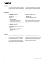
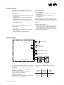
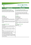
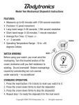
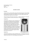
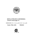
VEGAMET 307 / 308
TIB • Technical Information • Operating Instructions
Signal conditioning
instrument
for continuous level
measurement
20
0
60
40
%
• for connection of a
capacitive measuring
electrode
80
100
or
• a pressure sensor
0 mA4
AB
VEGAMET 308
VEGA Grieshaber KG
Am Hohenstein 113
Postfach 11 42
D-77757 Schiltach
Phone 0 78 36/50-0
Fax 0 78 36/50-201
Application
These signal conditioning instruments VEGAMET
307 / 308 are used for level proportional output and
indication of levels (continuous level measurement).
The VEGAMET 308 is additionally equipped with
an integral level switch with adjustable switching
hysteresis. Therefore level dependent switching
functions are possible.
Configuration
The VEGAMET 307 consists of:
A measuring system consists of:
• plastic housing with pluggable multipoint connector (series 300)
• electronics
• front panel with
- analog indicating meter
- mains control lamp
- potentiometer for empty adjustment
- potentiometer for full adjustment
- change-over switch for current output range
0 … 20 mA or 4 … 20 mA.
• signal conditioning instrument VEGAMET 307 or
VEGAMET 308
• capacitive electrode with oscillator
or
• pressure sensor with oscillator
Additional indicators and auxiliary level switches
can be connected to the current and voltage
outputs.
The VEGAMET 308 consists of:
• as VEGAMET 307
• however additional adjustment elements for the
level switch:
- 2 pressure keys and 2 potentiometers for
adjustment of the switch points
- relay control lamp
- A/B-switch
Function
Level measurement with capacitive electrodes
Level measurement with pressure sensors
Electrode, product and vessel wall, or electrode
and product form a capacitor. The capacitance
increases with increasing level.
The diaphragm of the pressure sensor converts the
hydrostatic pressure of the product into a linear
movement. This movement is transmitted to the
plunger-type capacitor. The level of the product
therefore changes the capacitance.
In either case the oscillator converts this capacitance change into a level proportional measuring
signal. This signal is fed to the VEGAMET 307 or
308 for signal conditioning.
2
VEGAMET 307 / 308
Technical data
Power supply
20 … 250 V AC; 48 … 62 Hz
20 … 90 V DC
Power consumption at UN
approx. 3 VA
Measuring signal
input
Connection line
Resistance per conductor
Linearity error
Temperature error
2-wire, unscreened (standard cable)
max. 50 Ohms
0,1 % measuring range
0,01 % measuring range / 10 K
Adjustment data
Empty adjustment range
Current difference between
empty and full adjustment:
3,5 … 17 mA
Indication
Current output
Voltage output
Relay output
(only VEGAMET 308)
> 600 µA
analog indication 0 … 100 %
Range
Load
Resolution
Linearity error
Temperature error
0 … 20 mA or 4 … 20 mA
(adjustable)
max. 750 Ohm
0,05 %
0,025 % measuring range
0,025 % measuring range / 10 K
Range
Resolution
Linearity error
Temperature error
0 … 10 V, max. 1 mA (short-circuit protected)
0,05 %
0,025 % measuring range
0,025 % measuring range / 10 K
Contact
Function
Mode
Relay data:
Contact material
min. turn-on voltage
switching current
max. turn-on voltage
switching current
max. breaking power
1 spdt
two-point switching
A/B
AgCdO and Au plated
10 mV
10 µA
AC 250 V, DC 60 V
AC 2A, DC 1 A
125 VA, 60 W
Permissible ambient temperature (housing)
Storage and transport temperature
–25°C … +60°C / –4°F … +140°F
–25°C … +70°C / -4°F … +158°F
Housing
plastic ABS
IP 40
w = 96 mm, d = 76 mm, h = 102 mm
Type
Protection
Dimensions
Pluggable multipoint connector (cross section area of conductor)
max. 2,5 mm2
Weight
approx. 270 g
VEGAMET 307 / 308
3
Dimensional drawing
Surface mounting
80
Adapter
Terminal board
20
80
100
105
%
96
102
41
92
60
40
0
AB
0 mA4
VEGAMET 308
5
Metal link
76
96
3
with transparent cover
89
Panel mounting
92
20
0
60
40
80
100
15
41
125
119
%
0 mA4
on
VEGAMET 307
110
42
9
Iso-housing IP 55 for series 300 (Option)
20
0
40
60
%
0 mA 4
157
ø4,5
80
100
AB
VEGAMET 308
100
4
125
9
107
VEGAMET 307 / 308
Mounting instructions
The instrument is suitable for panel or surface
mounting. The required parts are attached.
Surface mounting
a) Screw fastening
• Push the metal sleeve in the instrument cut-out
(see sketches)
• Fasten the instrument with 3 screws to the
mounting plate.
Panel mounting
• Pull pluggable multipoint connector on the instrument upwards.
• Screw in and fasten the pin on the rear of the
instrument.
• Push instrument into the front panel cut-out.
• Push the terminal from the back on the pin and
fasten with the screw.
For increased protection, Iso-housing with transparent cover (protection IP 55) is available (mounting
of the instrument into the housing as described
under a).
b) Rail mounting (Snap-in)
• Fasten adapter plate for rail TS 35 x 7,5 mm acc.
to EN 50 022 on the back of the instrument with
a screw (spring of the adapter must be below).
• Plug the instrument from the bottom to the carrying rail and push until snap-in.
When using the lockable transparent cover proceed as follows:
• Open cover.
• Push the frame from the back over the upper
instrument edge.
• Further mounting as described above.
Electrical connection
14
L (+)
13
N (-)
Mains connection
12
11
10
Relay output
(with VEGAMET 308)
9
8
+
7
-
6
+
5
-
4
Current output 0/4 … 20 mA
Voltage output 0 … 10 V
3
-
2
2
2
+
1
1
1
VEGAMET 307 / 308
Pressure sensor
with oscillator
The electrical connection is made on the multipoint
connector acc. to the diagram on the upper part of
the housing.
Standard 2-wire cable can be used between
VEGAMET and transducer.
If electromagnetic interference is expected,
screened cable should be used.
Protective measures:
If voltage spikes are expected, the use of overvoltage arresters is recommended.
VEGAMET 307 / 308
Electrode
with oscillator
Observe TIB "overvoltage arresters" for their
connection!
Indicated
value
Current
output
Voltage
output
0%
0 / 4 mA
0V
100 %
+ 20 mA
+ 10 V
5
Indicating and operating elements
20
60
40
0
%
0 mA 4
80
100
AB
VEGAMET 308
Multipoint
connector
Indicating meter
Potentiometer for
empty adjustment
only VEGAMET 308
Key for indication and
adjustment of the max.
switch point
Potentiometer for
adjustment of the
max. switch point
Switch for
current output
Potentiometer for
adjustment of the
min. switch point
Potentiometer for
full adjustment
Key for indication and
adjustment to the min.
switch point
Mains control lamp
A / B switch
Relay control lamp
Start-up
• Adjust the requested current output range
0 … 20 mA or 4 … 20 mA.
• Carry out adjustment and switch point adjustment
(VEGAMET 308) acc. to the following description.
• Feed supply voltage, should comply with the
voltage stated on the connection diagram.
6
VEGAMET 307 / 308
Adjustment
Empty and full adjustment via the spindle potentiometer. The integrated slide clutch avoids overwinding.
Before either adjustment each potentiometer must
be turned by approx. 22 turns clockwise.
In practice 3 versions are possible to carry out the
empty / full adjustment.
a) The level can be set to the required min. level
(= 0%) and max. level (= 100 %)
Empty adjustment
• Set level to the required min. level.
• Adjust the indication of the instrument to 0 % by
the potentiometer for empty adjustment.
Full adjustment
Empty adjustment
• Set product to the low level and check with dip
measure (e.g. 20 %)
• Set indication of the instrument to 0 % with the
potentiometer for empty adjustment.
Full adjustment
• Set level to highest possible level and check with
dip measure (e.g. 60 %).
• Calculate the indicated value to be adjusted:
highest level minus lowest level = indicated value
to be adjusted.
In the example: 60 % – 20 % = 40 %.
• Set indication of the instrument to the calculated
value (in the example 40 %) with potentiometer
for full adjustment.
• Set the indication of the instrument to the actual
level (highest level, in the example 60 %) with
the potentiometer for empty adjustment.
• Set level to the required max. level.
• Adjust the indication of the instrument to 100 %
by the potentiometer for full adjustment.
b) The level in the vessel can be set to the
required min. level (= 0 %), but only to a max.
level < 100 %
Empty adjustment
• Set level to the required min. level.
• Adjust the indication of the instrument to 0 % by
the potentiometer for empty adjustment.
Full adjustment
• Set product to the highest level and check with
dip measure (e.g. 80 %).
• Adjust the indication of the instrument to the
checked value (in the example 80 %) with the
potentiometer for full adjustment.
c) The level in the vessel can be only set to a
min. level of > 0 % and a max. level ≤ 100 %
VEGAMET 307 / 308
7
Switch point adjustment (only possible on VEGAMET 308)
• Set A/B-switch acc. to the following description to the desired mode A or B.
Mode A
When exceeding the adjusted max. level:
Relay de-energized
Relay control lamp lights
Terminals 9-10 are connected through relay
Mode B
When decreasing the adjusted min. level:
Relay de-energized
Relay control lamp lights
Terminals 9-10 are connected through relay
• Adjust switch point for min. level
Push button for adjustment of the min. switch point and adjust the potentiometer of
the indicating instrument to the desired min. value.
• Adjust switch point for max. level
Push button for adjustment of the max. switch point and adjust the potentiometer
of the indicating instrument to the desired max. value.
Adjustment for single-point switching
• Push button for adjustment of the max. switch point and set the indicating instrument with the respective potentiometer to "0".
• Push button for adjustment of the min. switch point and set the indicating instrument with the respective potentiometer to the required value.
Note:
The switching hysteresis is in this case 0,5 %.
VEGA Grieshaber KG
Am Hohenstein 113
Postfach 11 42
D-77757 Schiltach
Phone 0 78 36/50-0
Fax 0 78 36/50-201
Technical data subject to alterations
2 16 366 / April '93