1
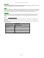
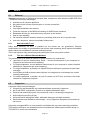
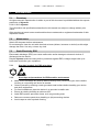
MS-812 – User’s manual © - Revision 1.9 MS-812 - User’s manual This symbol is intended to alert the user of important operating and maintenance (servicing) instructions in the literature provided with the equipment. This symbol is intended to alert the user of the presence of uninsulated dangerous voltage within the product’s enclosure that may present a risk of electric shock. 1 Caution Read Instruction: Read and understand all of the safety and operating instructions before using this equipment. Retain Instructions: The safety instructions should be kept for future reference. Follow Warnings: Follow all warnings and instructions marked on the equipment or in the user manual. Avoid Attachments: Do not use tools or attachments that are not recommended by Alyseum because they may be hazardous. ● ● ● Installation: Choose the installation location of your unit carefully. Avoid placing it in direct sunlight or close to a source of heat. Also avoid locations subject to vibrations and excessive dust, heat, cold or moisture. Power Source: This equipment should only be operated from the power source indicated on the product. Servicing: Refer all servicing to qualified service personnel. There are no user-serviceable parts inside. WARNING: TO PREVENT FIRE OR ELECTRIC SHOCK HAZARD, DO NOT EXPOSE THIS APPLIANCE TO RAIN OR MOISTURE. Page 1 MS-812 – User’s manual © - Revision 1.9 2 Contents 1 2 3 Caution............................................................................................................................................ 1 Contents.......................................................................................................................................... 2 What’s the MS-812 ? ...................................................................................................................... 3 3.1 Features in MIDI mode........................................................................................................... 3 3.2 Features in CopperLan mode ................................................................................................ 3 3.3 Specifications ......................................................................................................................... 4 4 Hardware......................................................................................................................................... 5 4.1 Package content..................................................................................................................... 5 4.2 Accessoiries ........................................................................................................................... 5 4.3 Front panel description........................................................................................................... 6 4.4 Rear panel description ........................................................................................................... 7 4.5 Reference voltage tuning ....................................................................................................... 7 5 Software .......................................................................................................................................... 8 5.1 CopperLan Manager .............................................................................................................. 8 5.1.1 5.1.2 5.2 5.3 Merging function................................................................................................... 8 Establish connections........................................................................................... 8 How to connect the MS-812 to MIDI? .................................................................................... 9 Using the interface ............................................................................................................... 11 5.3.1 5.3.2 5.3.3 5.3.4 5.3.5 5.3.6 5.3.7 Overall structure ................................................................................................. 11 The Main (root) device ....................................................................................... 12 The Performance sub-device ............................................................................. 12 The voice processors ......................................................................................... 13 Settings of the voice processors ........................................................................ 13 Notes about the various settings ........................................................................ 13 The Clocks sub-device ....................................................................................... 14 5.4 Settings ................................................................................................................................ 15 5.5 Firmware Upgrade software................................................................................................. 15 6 About............................................................................................................................................. 16 6.1 Ethernet................................................................................................................................ 16 6.1.1 6.1.2 Note about Wi-Fi use.......................................................................................... 16 Tips for a efficient Ethernet Network .................................................................. 16 6.2 CopperLan............................................................................................................................ 16 7 Miscellaneous ............................................................................................................................... 17 7.1 Disclaimer............................................................................................................................. 17 7.2 Maintenance......................................................................................................................... 17 7.3 Static Electricity, ESD........................................................................................................... 17 7.3.1 7.3.2 7.4 7.5 7.6 How to wire an Ethernet cable? ........................................................................................... 18 How to wire a DIN-SYNC24 cable ....................................................................................... 18 Statement and Agency Compliance..................................................................................... 19 7.6.1 7.6.2 7.6.3 7.7 7.8 Standard symbols for ESD advertising............................................................... 17 Some tips and precautions for ESD sensitive environment ............................... 17 WEEE (for EU countries)................................................................................... 19 RoHS Compliance (for EU countries)................................................................ 19 CE (for EU countries) ........................................................................................ 19 Warranty and repair.............................................................................................................. 19 MIDI Chart ............................................................................................................................ 20 Page 2 MS-812 – User’s manual © - Revision 1.9 3 What’s the MS-812 ? The Alyseum MS-812 is an embedded computer Board, using Ethernet network to Convert MIDI or CopperLan messages to CV and digital control voltages as used in modular and analog synthesizers. As the first Alyseum product dedicated to modular synthesizers, the MS-812 offers 8 CV outputs and 12 digital outputs. A SYNC24 interface is available as an alternative function on digital output jacks. (Adapter required) The MS-812 is supplied ready to use, the actual linking is managed via the CopperLan Manager software. This freeware tool is also used to monitor the status of other CopperLan capable computers and equipment. The MS-812 can be controlled and played from any computer anywhere in the network. The MS-812 is built around a powerful 32-bit processor offering 120 DMIPS ensuring low latency, and jitter High-quality 16 bits converters (Analog Devices) without sample & hold. 3.1 ● ● ● ● ● ● ● ● ● ● ● ● 3.2 Features in MIDI mode Modular MIDI interface to 8 CV Out and 12 Digital output 100% MIDI compatible via CopperLan Free assignment of MIDI channels and controllers Full MIDI range, 128 notes= 10 Volts 2/3 span (in the range -10v2/3 to +10v2/3). Smooth (polyphonic) portamento with no audible stepping Independent drum section Direct jack control capability for software applications Reception of two simultaneous clocks from independent sources Each CV Out can be used as note, setting control or modulation source Each DIG Out can be assigned as a Gate, Clock, Reset, status, control and more MIDI to DIN-SYNC24 converter. Fully editable in high-resolution from any computer in the network (over 200 parameters) Features in CopperLan mode Same as above, plus: ● Full CopperLan pitch range = continuously variable between minus 10 Volts 2/3 and plus 10 Volts 2/3. ● High-resolution pitch: 1/256 semitone precision with continuous pitch update ● Gating independent from pitch ● Gating, triggering, retriggering capabilities ● VoiceID management controls the polyphonic play as multiple mono independent voices ● High resolution control voltages - 65536 levels for zip-free control ● Expendable up to nine MS-812. Page 3 MS-812 – User’s manual © - Revision 1.9 3.3 Specifications Front Panel width: 91.5 mm (18HP) Module Depth: 40 mm max Outputs Jacks: 3.5 mm - ring/tip CV Output Level: from minus 10 Volts 2/3 to plus 10 Volts 2/3 CV Output Load: 2 KΩ minimum CV Output maximum current: 20 mA/Jack Digital Output Level: 0 or 5 Volts Digital Output maximum current: 20 mA/Jack ● Power requirements: o +12 Volts, regulated @ 90 mA o -12 Volts, regulated @ 10 mA ● 100 Base-T compliant Ethernet interface. ● Auto-MDIX allows the use of straight-trough or cross-over network cable. ● ● ● ● ● ● ● ● Page 4 MS-812 – User’s manual © - Revision 1.9 4 Hardware 4.1 ● ● ● 4.2 Package content 1 MS-812 module with Eurorack compliant front panel and supply connector 1 plastic bag containing: o 1 x 10/16 pins flat cable for Eurorack compliant power connector o 4 x M3 screws o 4 x M3 nylon washers Warranty & user’s manual access card Accessoiries DIN-SYNC24 adaptor cable - 4x 3.5mm male jacks to DIN 5 female – color coded http://www.alyseum.com/accessories Page 5 MS-812 – User’s manual © - Revision 1.9 4.3 Front panel description Alyseum 4 CV 1 CV 2 DIG 1 DIG 2 CV 3 CV 4 DIG 3 DIG 4 CV 5 CV 6 DIG 5 DIG 6 CV 7 CV 8 DIG 7 DIG 8 DIG 9 DIG 10 DIG 11 DIG 12 NOTE LK/ACT. 1 2 5 7 6 3 CLK 1 10-100 Base-T CLK 2 MS-812 1. 2. 3. 4. 5. 6. 7. Yellow LED – Link/Activity on the Ethernet network Ethernet LK/ACT Mode LED Pattern No connection OFF LINK established ON Network activity ON with OFF pulses Green LED – CopperLan activity with the unit CP activity Mode LED Pattern Firmware Upgrade ready Slow blinking Firmware Upgrade activity Fast blinking CP establishing connection OFF with ON pulses CP Activity ON with OFF pulses RJ45 – Ethernet connector Jack 3,5 mm – 8 x CV Out Jack 3,5 mm – 12 x Digital output with Green LED for status Red LEDs - flashes with incoming clock flows 1 and 2 (regardless of their actual use) Blue LED - flashes with any incoming notes (regardless of their actual use) Page 6 MS-812 – User’s manual © - Revision 1.9 4.4 Rear panel description +15V 8 COM FRAC COM -15V OR EURO 9 +12V COM COM COM -12V FULL RANGE TRIM 10 PIN 1 Alyseum More than Technology MS-812 MADE IN EEC 8. FRAC Power Connector, not available. 9. IEC 60603-13 (DIN 41651) 10 pins – Power Connector for Eurorack version only. 10. Position of the calibration trimmer behind the back panel Always follow the rules and recommendations of the power supply manufacturer before connecting the module. 4.5 Reference voltage tuning For expert only, need hi-precision voltmeter (20.000 points) A trimming potentiometer allows you to fine tune the voltage span of the analog converters. To ease the setting, there is a dedicated calibration preset (see 5.1.1) that gives various reference voltages on all CV outputs: Connect on CV out 1, and turn the trim to adjust the voltage precisely to 10,666 Volts. The other outputs are not used for calibration but rather to check that the module is OK at manufacturing. Page 7 MS-812 – User’s manual © - Revision 1.9 5 Software 5.1 CopperLan Manager Editing and establishing virtual connections to the MS-812 is done via the CopperLan Manager application software. The CopperLan Manager is part of the CopperLan Package available cost free from the CopperLan website http://www.copperlan.org This application software provides 4 different tabs for the management of a CopperLan network: 1. An Overview tab, displaying all machines and their current connections. 2. A Connect tab, to add/remove connections between device’s outputs and inputs. 3. An Edit tab, providing a universal way to edit parameters. 4. A Snapshot tab, to store network configuration and settings. Remember to save your settings after being done with editing. 5.1.1 Merging function Connecting two or more sources to the same destination, realizes a merging functions. Beware that MIDI does not allow merging every type of message at any time. Merging two sysex messages may lead to unpredictable results. More information on our application note: http://www.alyseum.com/download. 5.1.2 Establish connections It is possible to connect any source to any destination, as a whole virtual cable or according to message type. Establishing connections is done from the connection tab of the CopperLan Manager software application. To connect a whole virtual cable, select the appropriate source device and click on the MIDI connector icon. You complete the operation by selecting a destination. All messages appearing at the source will be transferred to the destination without any filtering or remapping. Instead of connecting a whole cable content, it is allowed to connect individually one or more message types according to the following split: 1. Note and Controller messages on a channel basis – these are channel messages Any of the 16 MIDI channels content can be linked separately 2. Clock messages (incl. clock control and song position messages) Any clock from any source can be connected to any destination. Note that MIDI destinations can only accept a single clock whereas CopperLan destinations can accept many. 3. Other messages (Sys) This selection covers all messages to the exception of messages in categories 1 and 2 here above. This linking is essentially used for SYS EX and MTC messages. It is meaningful to only connect sources and destinations of adequate messages type (e.g. Sys to Sys). However, it is allowed to connect any source channel to any destination channel, effectively realizing a channel remapping. More information on our application note: http://www.alyseum.com/downloads Page 8 MS-812 – User’s manual © - Revision 1.9 5.2 How to connect the MS-812 to MIDI? The MS-812 can be connected in MIDI easily. The first drawing do not necessarily represent an existing setup. They are chosen to demonstrate the power and flexibility of CopperLan’s virtual network, regarding MIDI connections. MS-812 Router + WI-FI CP-MIDI8 Wi-Fi iPad Ethernet USB or 1394 MIDI Page 9 AL-88 MS-812 – User’s manual © - Revision 1.9 To ease the understanding of the second drawings, Sources are represented by a DIN connector. This is purely symbolic, actually, Sources can be: ● Virtual, 100% compatible with any MIDI software running on MAC OS-X and Windows. ● Hardware, by all equipment based on CopperLan, which are implicitly MIDI compatible ● Hardware via all equipment that handles usual MIDI interfaces, connected to the CopperLan virtual network via USB, Firewire, Ethernet, etc. Managing connections for the entirety of a setup is done via the CopperLan Manager software (see chapter 5.1) NB: it’s impossible to connect the MS-812 with a virtual MIDI cable in the CopperLan Manager. CLK 1 CLK 2 CLK In Source 1 MIDI Channel 1 MIDI Channel 2 MIDI Channel 3 MIDI Channel 4 MIDI Channel 5 MIDI Channel 6 MIDI Channel 7 MIDI Channel 8 MIDI Channel 9 MIDI Channel 10 MIDI Channel 11 MIDI Channel 12 MIDI Channel 13 MIDI Channel 14 MIDI Channel 15 MIDI Channel 16 Monophonic Monophonic Monophonic Monophonic Monophonic Monophonic Monophonic Voice Voice Voice Voice Voice Voice Voice 1 2 3 4 5 6 4 Polyphonique 8 Voice Drum 12 Voice Direct Jack control CLK In Source 2 MIDI Channel 1 MIDI Channel 2 MIDI Channel 3 MIDI Channel 4 MIDI Channel 5 MIDI Channel 6 MIDI Channel 7 MIDI Channel 8 MIDI Channel 9 MIDI Channel 10 MIDI Channel 11 MIDI Channel 12 MIDI Channel 13 MIDI Channel 14 MIDI Channel 15 MIDI Channel 16 MS-812 CopperLan Network MS-812 Page 10 MS-812 – User’s manual © - Revision 1.9 5.3 5.3.1 Using the interface Overall structure The MS-812 internal structure is organized as a matrix where incoming messages can be allocated to the physical jacks. Before being delivered electrically, messages can be altered by various settings and processes. The Main device gives the identity of the product on the network and is heading the two sub-devices. Messages are entering the MS-812 in different places according to their type: ● The preset management is sent to the Settings Section. ● Performance (music and controls) messages are arriving at the Performance sub-device ● Clock messages have a dedicated Clocks Section with two entry points for clock 1 and 2 Root Device input 1 Preset handling Alyseum MS-812 Block diagram input 2 CV Jack control www.alyseum.com input 3 Digi Jack control Mono input n (1~7) VoiceID cache & mapper Voice 1 Pitch D D A Velocity A Trigger/Gate status & logic Event msg D Selector X msg 7x A Modifier A msg Comparator A 8 x gate OR D 8 x trigger OR D Modifier B msg 7 x Monophonic Voice Inputs VoiceID cache & mapper Perf. Subdevice Voices 2~8 Event msg 7 Poly input Pitch D D A Velocity A Trigger/Gate status & logic Voice 1 8 x Voice processor 8x Unified data Selector X msg D Modifier A msg A Modifier B msg Comparator D Global M&S processor Polyphonic 8 Voice Input Drum input Event msg mapping filter Gate logic Velocity D 12 A 8 Unified data A Drum 12 Voice Input Direct input Modifier & Selector range filter Modifier Selector 8 12 A CV allocation matrix 55 > 8 D Direct Jack Control Input Tick & divs Clocks Subdevice Clock input n (1~2) Clock logic State 8 Digital allocation matrix Polarity and pulse setting 94 >12 D D Reset D Fill-in D 2x 2 x Clock Inputs MS-812 - 07-Dec-11 Page 11 CV 1 CV 8 Dig 1 Dig 12 MS-812 – User’s manual © - Revision 1.9 5.3.2 The Main (root) device This device presents three entry points: 1. Preset management related messages (select, load, save, rename, …) 2. CV out jack role assignment messages – defining which data among those available will be issued by each CV jack as an electric signal 3. Digital out jack role assignment messages – defining which data among those available will be issued by each Digi jack as an electric signal 5.3.3 The Performance sub-device This sub-device presents 10 inputs: ● Seven identical monophonic sections ● One polyphonic section that can be adjusted to handle from one to eight voices. When set to one voice, it behaves the same as the other inputs, and thus becomes the eighth monophonic input. ● One drum input to trigger independent sounds relating to notes. ● One direct jack control section to be mainly used with computer applications Poly and Mono sections Performance messages can be sent separately to any of these 8 inputs. The Performance messages recognized are: ● Event (notes) - with high-res free pitch and dissociated gating and impulse (when sent from CopperLan sources) When the source is MIDI, the messages are Note on/off, the pitch obeys to semitones as defined by the note number, the gating is associated to the note-on/off status, and the impulse (relating to the velocity) is provided jointly within note on/off messages. ● Modifiers – Any of the 65K+ Modifiers can be handled in full 16-bit resolution (65536 values). Modifiers can be used as setting control (e.g. tune), performance data (e.g. pitch-bend), or both (e.g. portamento time). When the source is MIDI, the messages enter the CopperLan network as MIDI controllers, and the resolution is usually 7-bit (128 values). ● Selectors – Any of the 65K+ Selectors can be handled – When the source is MIDI, any of the usual 120 Controller messages can be used. Selectors can be used as setting control (e.g. gating mode), performance data (e.g. sustain pedal), or both (e.g. portamento switch) Being a subset of CopperLan, MIDI messages can act in real time on the voltages generated by the interface (e.g. pitch-bend, portamento time, etc). A learn function eases the control from any MIDI or CopperLan source without the need to know the actual message identity. Drum section This section receives up to 12 notes that can be mapped anywhere over an 8 octave range. In each octave, the first pair of jacks (CV1 and Dig1) will relates to the note C, the second pair to C#, and so on. The Dig jacks are issuing gate signals in relation to the note on/off status, the CV jacks provide a voltage relating to the attack velocity. The release velocity is deliberately ignored; the attack relating voltage is maintained up to the next attack event. Since there are only 8 CV out jacks, the last notes in each octave cannot issue the velocity signal. Page 12 MS-812 – User’s manual © - Revision 1.9 The editing allows adjusting the gain and offsetting velocity of the drum section. In case you don’t want to allocate too many CV jacks to control velocity, there is a convenient global velocity signal available. This signal is updated with the velocity of each incoming note in the drum section so that sounds that usually do not play simultaneously can benefit of individual velocity control through a single jack. Direct Jack Control section This section gives direct access to the jacks, by bypassing the various musically related processes. This capability is mostly useful for controlling the jacks by customizable software applications that need direct access to the logic statuses and voltage converters. 5.3.4 The voice processors The voice processors relate to the Mono and Poly sections. All together, the 8 performance inputs will feed up to 15 of the available voice processors (7x1 + 1x8). The polyphonic input can feed up to 8 processors depending on its polyphony limit setting; each mono input always feeds a single voice processor. Each voice processor extracts and converts the performance messages into various data. ● Note values (tone/pitch) can be transposed and processed with portamento ● Velocity (Impulse) can be adjusted in gain and offset ● Continuous data (Modifiers) can be adjusted in gain and offset, as well as compared again threshold values. It is the data generated by the voice processors that can be hooked up to the jacks. Any data type from any voice can be freely assigned to any jack (analog to analog and digital to digital). The list of offered data is very long compared to the number of jacks; this is what gives the richness and flexibility of the MS-812. It is also allowed to assign a given signal more than once to multiple jacks. 5.3.5 Settings of the voice processors The way the data is handled in the voice processors is depending on settings. In addition to editing, most of the settings can be modified in real time for interesting musical results. (e.g. the portamento time). Settings and real-time control are independent for each of the 8 inputs. All voices handled by the polyphonic input will share the same set of settings, while voices from each monophonic input act independently. All 8 inputs present the same panel of settings and realize the same treatment with only three exceptions, all relating to the polyphonic input: ● The number of voices actually handled from the total polyphony received can be set (1 to 8) ● There is a global poly gate signal combining all gates from the poly section voices ● There is a global trigger signal combining all triggers from the poly section voices 5.3.6 Notes about the various settings Voice management All inputs offer voice management based on a history buffer. For the mono inputs, this allows playing real mono synth techniques such as multi finger trills. In the poly section it handles intelligently the voicing allocation when there are more notes played than currently assigned outputs. Page 13 MS-812 – User’s manual © - Revision 1.9 Pitch wheel The pitch wheel message is recognized as expected but can also be preset “manually”. This gives the wheel a starting position when the preset is recalled. Learn The MS-812 implements a message identity learning feature. This is implemented on the Modifiers A and B, as well as Selector X. Once a message generator is connected to an input of the MS-812, activating the learn button will define the next incoming message as the matching source. Comparator A comparator module can act on a digital output in relation to an analog source; the output will depend on the current signal level compared to the two adjustable threshold levels (Floor and Ceiling). 5.3.7 The Clocks sub-device This sub-device presents 2 inputs. Each input can receive one clock flow and its related control messages. Each input processes messages from which it create various signals that can be hooked up to the digital output jacks. Clock signals Incoming message Signals generated Clock tick Tick Start from zero State becomes ON, Reset pulse Continue State becomes ON Stop State becomes OFF Fill-in Fill-in pulse Page 14 MS-812 – User’s manual © - Revision 1.9 5.4 Settings Settings for the Preset are available in the CopperLan Manager (Editor tabs) 1. Select a Preset (32) 2. Load a preset 3. Save to selected Preset. 4. Clear active Preset 5. Give a name to a Preset 6. Status The save is done automatically. 5.5 Firmware Upgrade software Upgrading the firmware is done via the network. This is done automatically through the CopperLan Manager via an internet connection. Page 15 MS-812 – User’s manual © - Revision 1.9 6 6.1 About Ethernet Alyseum products rely on Ethernet to transport data; compared to other solutions (USB, IEEE1394 ...) Ethernet offers many advantages: ● Available on all computer platforms ● No practical limit in setup size and span or in node connections ● Full Duplex ● Very high bandwidth & low Latency ● Frees the computer of the MIDI flow handling of USB/Firewire interfaces ● Embedded devices can work without any computer in the network ● Peer to peer capability ● Full electrical isolation between machines, preventing audio hum due to ground loops ● Low cost, ubiquitous, mature and reliable infrastructure 6.1.1 Note about Wi-Fi use Using these products via Wi-Fi is possible but the results are not guaranteed. Wireless transmissions are subject to perturbations that require data resending which implies unavoidable delays which are unsuitable for real-time musical purposes. This is why Alyseum only guarantees good performance when using wired network. 6.1.2 Tips for a efficient Ethernet Network The performance of an Ethernet network is always related to its weakest link. ● Use the WI-FI only for web browsing, Email, ... and the wired network of your computer for CopperLan and eventual audio streaming ● For large installations, use an additional network card in your computer to create a network dedicated to CopperLan and audio streaming. ● For large installations, preferably use Gigabit Ethernet switches to guarantee a better data exchange ● Avoid Ethernet HUB as these create collisions in messages that could hamper the overall network performance ● For small installations, if possible, set your IP network on Wi-Fi only, and reserve the wired network for CopperLan purposes. 6.2 CopperLan CopperLan offers many advantages: ● Connectivity guaranteed with any hardware/software supporting CopperLan. ● No IP and DHCP configuration, thanks to an address abstraction layer. ● Protocol and networking system for command & control + streaming management. ● Self configuring and Plug & Play. ● Universal remote editing with labels, dedicated data types and high resolution. ● Decentralized work distribution and storage – every CopperLan equipment incorporates its own server. CopperLan manages MIDI in a more powerful and flexible than any other technology available. The benefit of having its own dedicated protocol surpasses the afterthought solutions relying on TCP/UDP-IP in terms user-friendliness. Page 16 MS-812 – User’s manual © - Revision 1.9 7 Miscellaneous 7.1 Disclaimer All rights reserved. Reproduction in whole or part of this document is prohibited without the express permission of Alyseum. © 2011-2015 Alyseum The information and specifications described in this manual are subject to change without prior notice Other products or brand names mentioned herein are trademarks or registered trademarks of their respective holders. 7.2 Maintenance Switch Off the power before maintenance. Do not attempt to clean the unit with chemical solvents (thinner, benzene or alcohol) as this might damage the finish. Use only a clean, dry cloth. 7.3 Static Electricity, ESD Electrostatic discharge (ESD) can cause malfunction and/or damage to electronic devices if discharged into the device. Despite Alyseum products having built-in protections against ESD, voltages might build up at levels that could harm your equipment. 7.3.1 Standard symbols for ESD advertising 7.3.2 Some tips and precautions for ESD sensitive environment ● ● ● ● ● ● ● Make sure to discharge any built-up static electricity from yourself and your device before touching or connecting one device to another Ground yourself by touching a earth grounded metal surface before handling your device and other equipments. For fixed installations, place the device in a grounded metallic rack. Ensure air relative humidity at minimum 60%. Install ESD specific prevention items, such as grounding mats. Reduce movement speed when handling or (dis)connecting devices Avoid carpet or other synthetic flooring. Page 17 MS-812 – User’s manual © - Revision 1.9 7.4 How to wire an Ethernet cable? If you want to build your own Ethernet cable, use CAT5 cable, RJ45 connectors and a crimping clamp. The maximum length for a single cable is 100 meters 7.5 Pin Function 1 TX+ 2 TX- 3 RX- 6 RX+ 1 8 How to wire a DIN-SYNC24 cable Pin Function Color Jack 1 Run (Start/Stop) Red 3 2 GND (Shield) -- 5 3 CLK 24PPQN Black 4 Reset / Start Blue 5 Fill-in / Continue Yellow 1 4 2 DIN41524 female 5 pins Page 18 MS-812 – User’s manual © - Revision 1.9 7.6 7.6.1 Statement and Agency Compliance WEEE (for EU countries) Waste Electrical and Electronic Equipment (Directive 2002/96/EC) (Applicable for E.U. Customers or others countries with separate collection systems) 1. This marking shown on the product or its literature, indicates that it should not be disposed with other household wastes at the end of its working life. 2. To prevent possible harm to the environment or human health from uncontrolled waste disposal, please separate this from other types of wastes and recycle it responsibly to promote the sustainable reuse of material resources. 3. Household users should contact either the retailer where they purchased this product, or their local government office, for details of where and how they can take this item for environmentally safe recycling. 7.6.2 RoHS Compliance (for EU countries) Alyseum products comply with the European Union restriction of the use of certain hazardous substances in electronics equipment, (RoHS directive 2002/95/EC) The RoHS directive prohibits the sale of certain electronic equipment containing some hazardous substances such as Mercury, Lead, Cadmium, Hexavalent chromium and certain Flame-retardants (PBB & PBDE) in the European Union. http://eur-lex.europa.eu/LexUriServ/LexUriServ.do?uri=CELEX:32002L0095:EN:HTML 7.6.3 CE (for EU countries) Alyseum products comply with the requirements of European Directive 89/336/EC. 7.7 Warranty and repair Alyseum warrants to you, the original purchaser, that each of its products will be free from defects in materials and workmanship for a period of two years from the date of purchase. This warranty does not apply to any products which have been repaired or altered by other than repair personnel authorized by Alyseum, or which have been subject to ESD, moisture, abuse, accident or improper installation and use. Alyseum assumes no liability as a consequence of such events under the terms of this Warranty. Please consult your shop for more details. Page 19 MS-812 – User’s manual © - Revision 1.9 7.8 MIDI Chart MS-812 MIDI IMPLEMENTATION CHART ver.1.0. Function 2011-03-30 Transmitted Recognized Remarks Default -- 1-16 Changed -- -- via network mapping Default -- -- not applicable Messages O O Altered -- -- 0-127 0-127 O X Keys O X Channels O X Pitch Bend O X Control Change O X Prog. Change True# O X System exclusive O O Song Position O O Song Select O O Tune Request O O Clock O X 2 sets Commands O X 2 sets Local On/Off O O All Notes Off O X Active Sensing O X System Reset O O Basic Channel Mode Note Number Velocity not applicable After Touch System Common 1-32 System Realtime Aux Messages Notes X= yes, O = no Page 20 via CopperLan